iTextAlert ITA1SENAA ITA-1 Sensor AA User Manual Quick Start Guide
iTextAlert LLC ITA-1 Sensor AA Quick Start Guide
Quick Start Guide
Quick Start Guide
Model iTA-1 Rev. A
iTextAlert, LLC
111 East First Street
Geneseo, Illinois 61254
Customer Service: 855-810-2992
www.iTextAlert.com
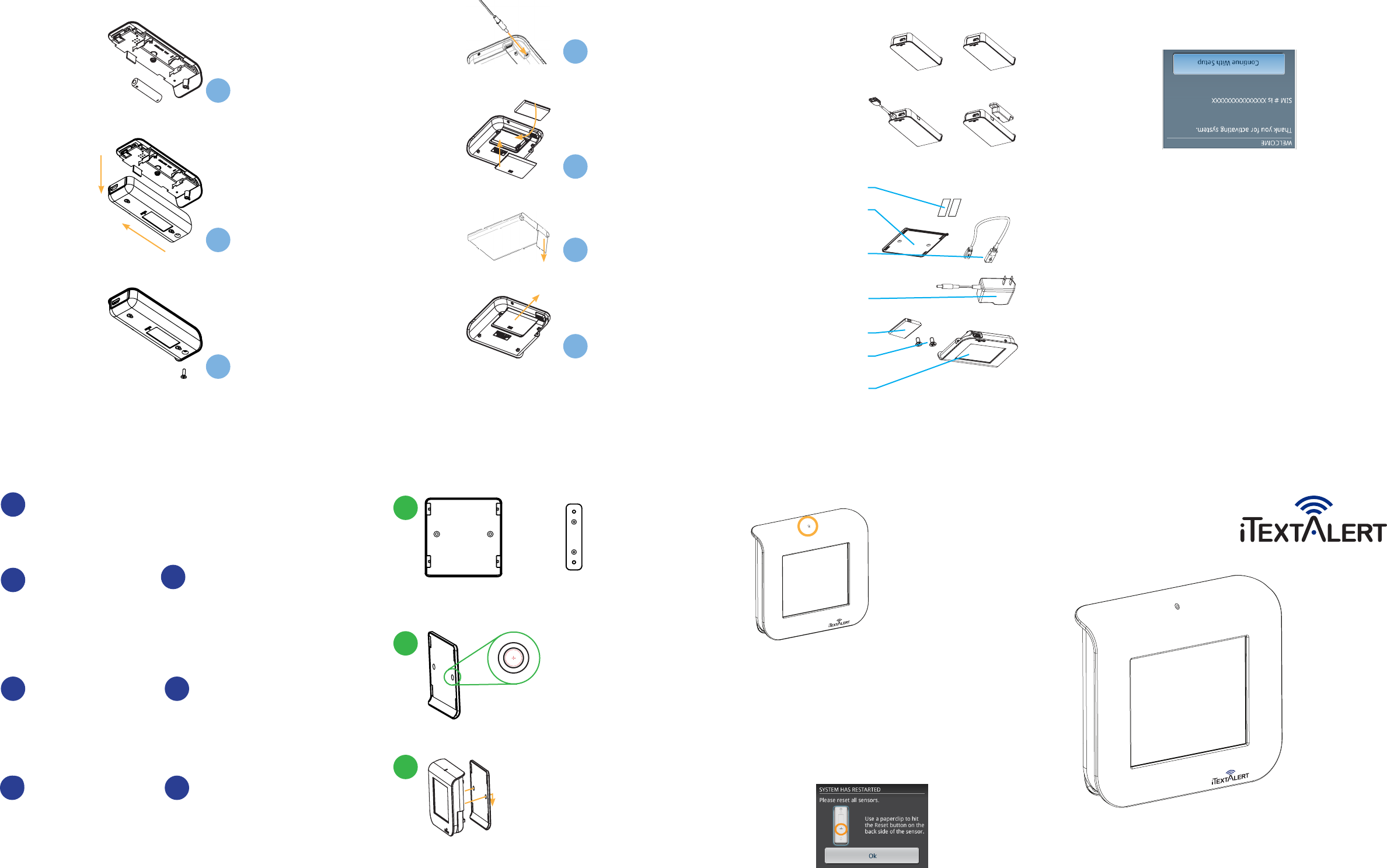
Setup Wizard
Power On
Install included Li-ion battery
into Hub. Connect the included
AC power adapter to Hub.
1
Activation
Log into www.iTextAlert.com or
call 855-810-2992 to activate
the system. Once activation
has been completed, follow the
on-screen instructions.
2
Hub Name
Enter a name or identifier
for the Hub. This is the
identifying name that you (and
your designated contacts) will
receive SMS (text) messages
from on your cell phone.
5
Password
You have the option to create
a four-digit password that
would allow only you to make
changes to the system settings.
3Sensors
Connect sensors to the
Hub via the provided USB
cable and follow on-screen
instructions to synchronize the
sensors with the Hub.
6
Wi-Fi
Connecting to a Wi-Fi network
provides a second method for
the Hub to transmit alerts to
your cell phone. If there is no
Wi-Fi network or the network
4Contacts
Enter the name(s) and cell
phone number(s) of those
persons that are to be notified
of any alerts via SMS (text)
messaging.
7
REF. DOC. QS-ITA1 REV A, 10/2011
FCC ID: Z3GITA1HUB
becomes disabled, the Hub
will transmit alerts using the
cellular telephone network.
The Hub can only connect to
one Wi-Fi network.
Welcome,
Thank you for purchasing the iTA-1 monitoring and alerting
system. With this product, you have the ability to monitor up
to 8 remote sensing devices using wireless technology and
the convenience of your cell phone. The iTA-1 allows you to
receive alerts from and to send commands to your Hub via SMS
(text) messaging.
To begin using your system, please register either logging into
www.iTextAlert.com or calling 855-810-2992. Please note that
the activation reminder will be present on your Hub until it has
been registered. You will not receive SMS alerts to your cell
phone until you have completed activation.
For customer service or technical support, please call 855-810-
2992 between the hours of 7:00 AM to 7:00 PM Central time
zone, Monday through Friday or visit us at www.iTextAlert.com.
Activation
Per FCC 15.21 changes or modifications not expressly approved by the party responsible for compliance
could void the user’s authority to operate the equipment.
Per FCC 15.19(a)(3) This device complies with part 15 of the FCC Rules. Operation is subject to the
following two conditions: (1) This device may not cause harmful interference, and (2) this device must
accept any interference received, including interference that may cause undesired operation.
Hard Key Functions
•Press and hold hard for 5 seconds to place Hub in sleep mode.
•Press and release the hard key to wake the Hub from sleep
mode. (Note: Do not hold the hard key down.)
If the system shuts down, use a paperclip to hit the Reset button on
the back side of the Sensor. Push in carefully until the button clicks.
Hub Hard Key
The hard key is used to put
the Hub in sleep mode, wake
the Hub up from sleep mode,
and reboot the system. The
Hub will only power down
when the battery pack is
depleted.
Installing The Sensor’s Battery
Remove screw from back battery cover.
1
Slide battery cover to access battery area.
2
3
Insert battery according to diagram.
Hub & Sensor Item List
1 - iTextAlert Hub with built-in power
Sensor (control panel)
2 - mounting screws
1 - Rechargeable Li-ion battery
(3.7V, 1150 mAh, 4.3 Wh)
1 - AC power supply
(Input: 110-120V, 50-60 Hz, 0.15A
Output: 5V, 1A)
1 - USB cable
1 - USB plug (to protect the port)
1 - wall mount or desk stand bracket
2 - pieces of double-sided tape
Quick Start Guide
Items included with the optional
Sensor packages:
1 - wall mount bracket
1 - USB plug (to protect the port)
2 - mounting screws
1 - AA or AAA battery
2 - piece of double-sided tape
Quick Start Guide
Open/Close Sensor
Temperature Sensor
Wet/Dry Sensor
Stationary/Move Sensor
Wall Mount Installation (Hub and Sensors)
Use the mounting bracket as a template to mark
pilot holes for the mounting screws.
Pilot holes may not be necessary in some materials
1
Sensor wall mountiText Hub wall mount
Drill 1/16” pilot holes. Install the mounting bracket
using the included screws.
2
Fasten the Hub or Sensor to the bracket.
The double-sided tape may be used to fasten the mounting bracket
instead of securing with the screws.
3
Installing The Hub’s Battery
Slide Hub cover to access battery area.
1
Pull battery tab from battery.
2
Plug in supplied AC power adapter to Hub.
4
Replace battery and cover on Hub.
3
Note: the Hub will not operate without the battery installed.
Please install battery prior to operating the device.
Note: please push on the power button to access the hard key.
Note: Hub must have battery installed and AC adapter plugged in to opterate.
Please cut along the dotted lines for a quick reference sheet.
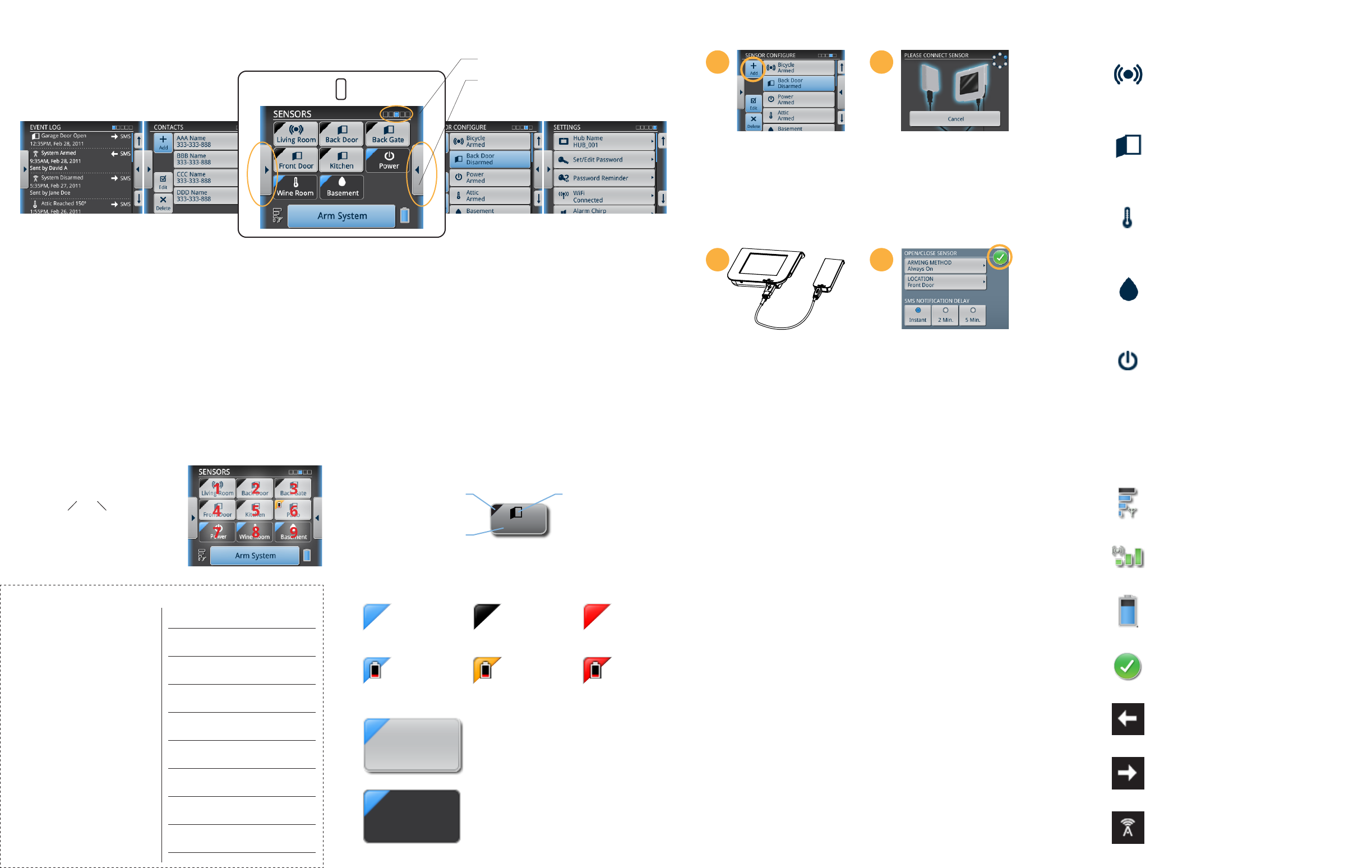
Remote Configuration
Commands:
You can send a SMS command to the Hub.
XY
Command Sensor
1Y - Disarm
2Y - Arm
3Y - Dismiss
ex. Send “25” will Arm Sensor 5 (Kitchen)
Sensor Screen Grid Number
Reply
Commands
Sensor List
The commands allow you to communicate with your Hub via SMS on your
mobile device.
3 or MENU - Option Menu
4 or DISARM - Disarm System
5 or ARM - Arm System
6 - Reply to see Disarmed Sensor List
7 - Reply to see Armed Sensor List
8 or STATUS - Reply Sensor Disarmed/Armed Status
9 or TEST - Send Test SMS to all contacts
11 to 19 - Disarm individual Sensor
21 to 29 - Arm individual Sensor
31 to 39 - Dismiss individual Sensor
SMS Notifications
Stationary/Move - alerts once the
Sensor is physically moved.
Open/Close - alerts once the
Sensor disconnects/connects.
Temperature - alerts once the
Sensor has reached its threshold.
Wet/Dry - alerts the Sensor has
reached the wet/dry level based
on its configuration.
Power - alerts once the Hub has
lost or regained power.
Sensor Types
SMS signal strength
Wi-Fi strength
Hub battery level
Settings confirmation
Incoming SMS
Outgoing SMS
Entire system
Other Graphics
3 or OPTION
4 or DISARM
5 or ARM
6
7
8 or STATUS
9 or TEST
Option Menu
Disarm System
Arm System
Reply to see
Disarmed Sensor List
Reply to see
Armed Sensor List
Reply to see all
Sensor Disarmed/
Armed Status
Send Test SMS to all
contacts
11-Disarm 21-Arm 31-Dismiss
12-Disarm 22-Arm 32-Dismiss
13-Disarm 23-Arm 33-Dismiss
14-Disarm 24-Arm 34-Dismiss
15-Disarm 25-Arm 35-Dismiss
16-Disarm 26-Arm 36-Dismiss
17-Disarm 27-Arm 37-Dismiss
18-Disarm 28-Arm 38-Dismiss
19-Disarm 29-Arm 39-Dismiss
1.
3.
2.
4.
5.
6.
7.
8.
9.
Sensor Status
Status Indicator
Status Indicator
Sensor Type
Sensor Location
Kitchen
Armed With System
The Sensor will arm when selected on the
Sensor Menu or when the system is armed.
Always On
The Sensor will remain armed even
when the system is disarmed.
Sensor
Armed
Sensor
Disarmed Sensor Alert
Sensor
Armed
Battery Low
Sensor
Disarmed
Battery Low
Sensor Alert
Battery Low
Contacts
Lists the designated contacts
(maximum of 5).
Event Log
Chronologically lists the last 50
system events.
Sensors
Lists the maximum of 9
sensors (Power is a default
Sensor).
Settings:
Lists the settings for the
Hub and Sensors.
Sensor Configure
Lists all the sensors, their
types, and their locations.
From this screen, individual
sensors can be edited or
deleted.
Note: After the initial setup,
Sensor Settings can be edited
without connecting the Sensor to
Hub via the provided USB cable.
Menu Navigation
Screen
position
Press the right or left
scroll buttons to access
the different menus.
Additional Sensors
Go to Sensor Configuration screen
and press [+ symbol] to add a
Sensor (maximum of 8).
1
2
The connecting screen will appear;
once the Hub recognizes the
Sensor, the screen will advance to
the specific Sensor Settings screen.
Adjust the settings; then press the
[√ symbol] to confirm the settings.
Connect the Sensor to the Hub via
the provided USB cable.
3
4
Note: When resetting the sensor, it is not required to connect the
Sensor to the Hub via USB cable.