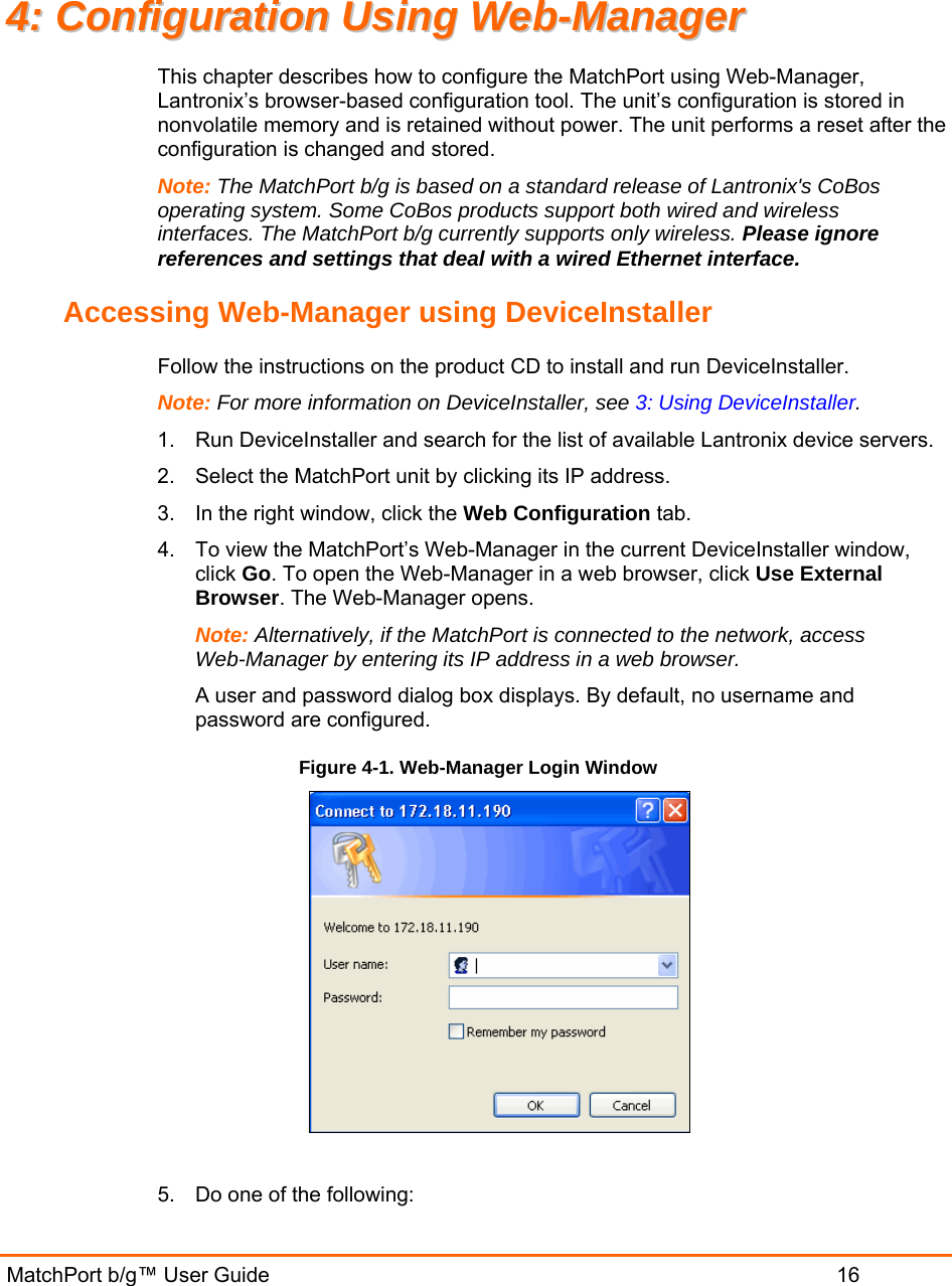
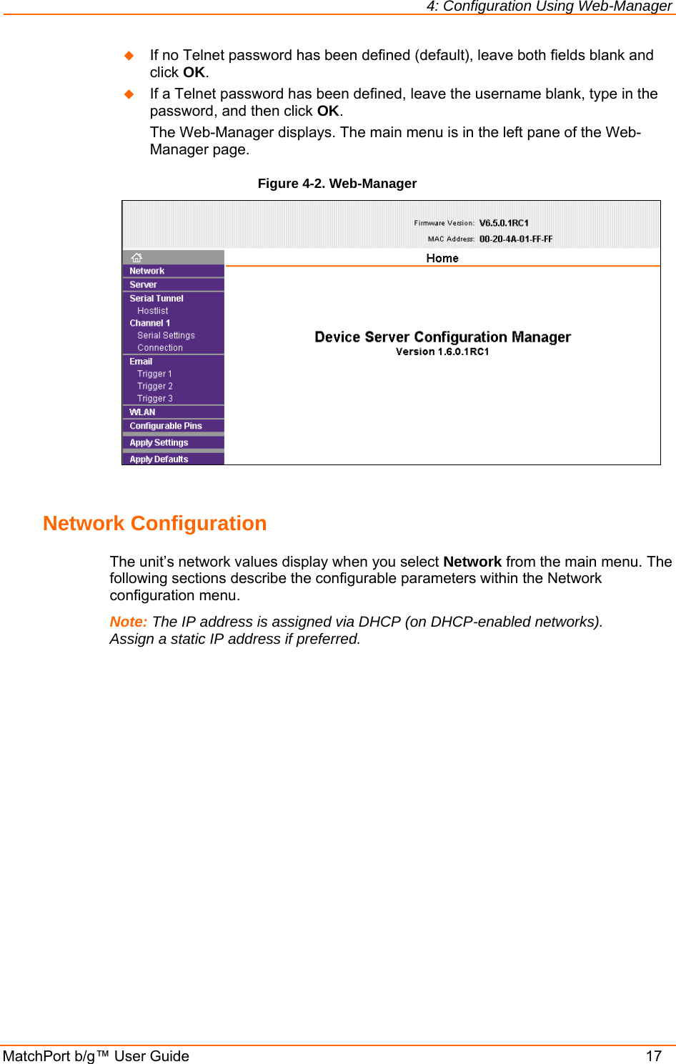
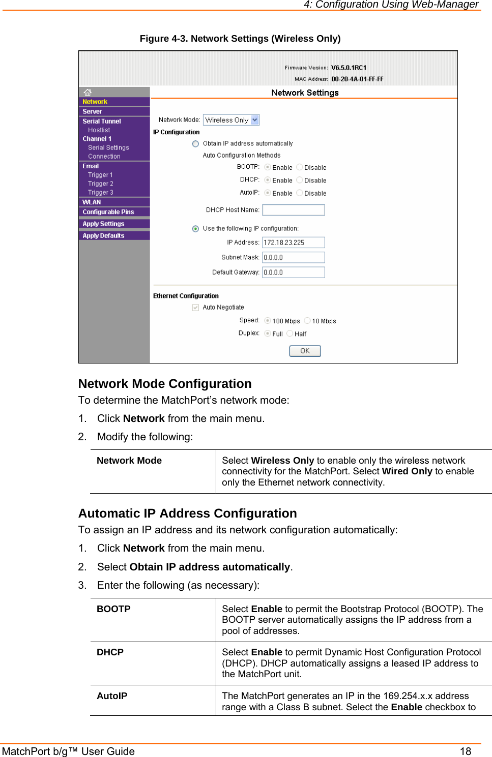
Lantronix MTCHDRCT Wireless Device Server User Manual MatchPort b g Direct User Guide
lantronix Wireless Device Server MatchPort b g Direct User Guide
UserManual.wiki
>
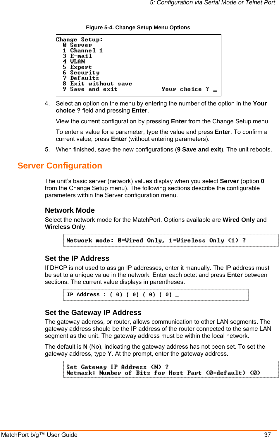
Lantronix
>
MTCHDRCT User Manual
User manual
Navigation menu
Upload a User Manual
Namespaces
Wiki Guide
HTML
PDF
Info
Views
User Manual
Discussion / Help
Navigation
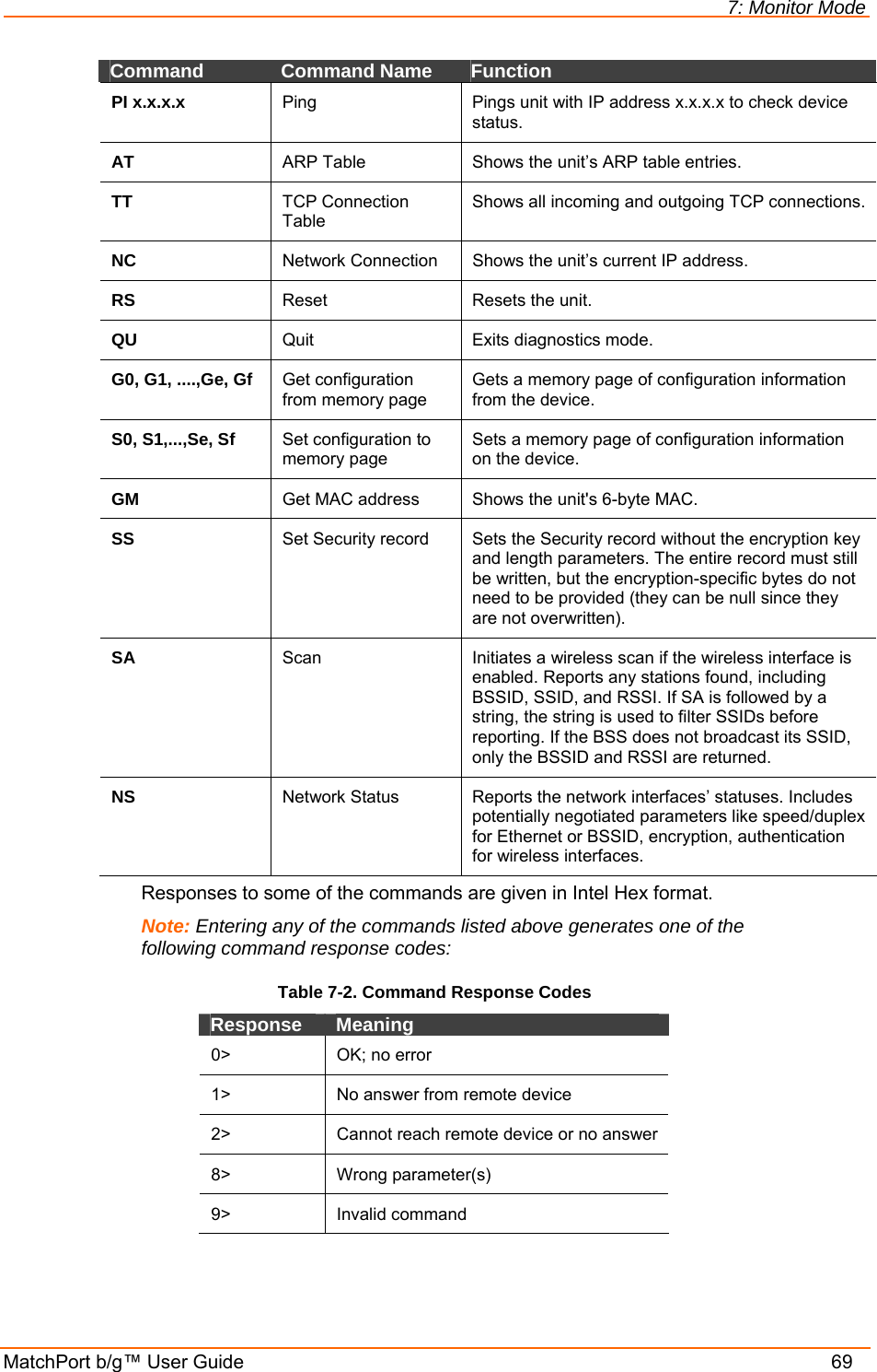
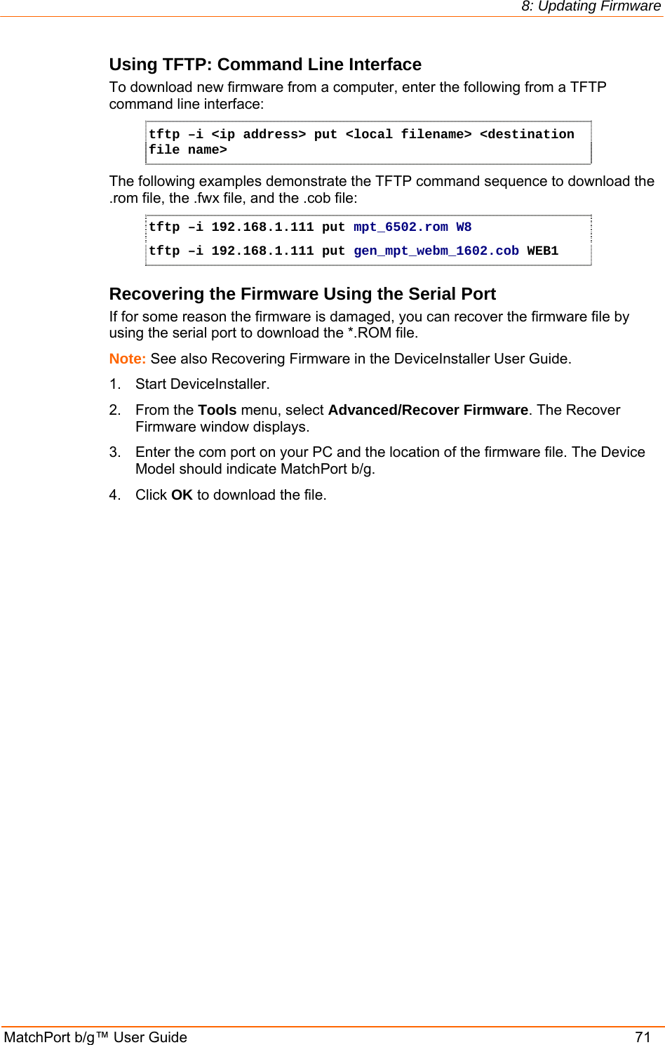
![4: Configuration Using Web-Manager MatchPort b/g™ User Guide 31 WLAN Configuration Without adequate protection, a wireless LAN is susceptible to access by unauthorized users. Note: Due to regulations, the country-specific setting has been removed from the setup menu and Web-Manager. However, we provide a separate utility for changing the Country/Zone setting. The utility is called SetZone and is included in the MatchPort package. It is also available for download from the Lantronix web site. The syntax is SetZone <IP address> [<zone abbreviation>] Leaving the zone blank causes the utility to report the current setting only. Following are valid zone abbreviations. These settings are consistent with IEEE802.11b/g zones: US=United States CA=Canada FR=France SP=Spain JP=Japan OT=Others, such as Europe (excluding France), Asia, Africa, and Australia To configure the MatchPort’s WLAN settings: 1. On the main menu, click WLAN to open the WLAN Settings page. Figure 4-12. WLAN Settings](https://usermanual.wiki/Lantronix/MTCHDRCT/User-Guide-801310-Page-31.png)

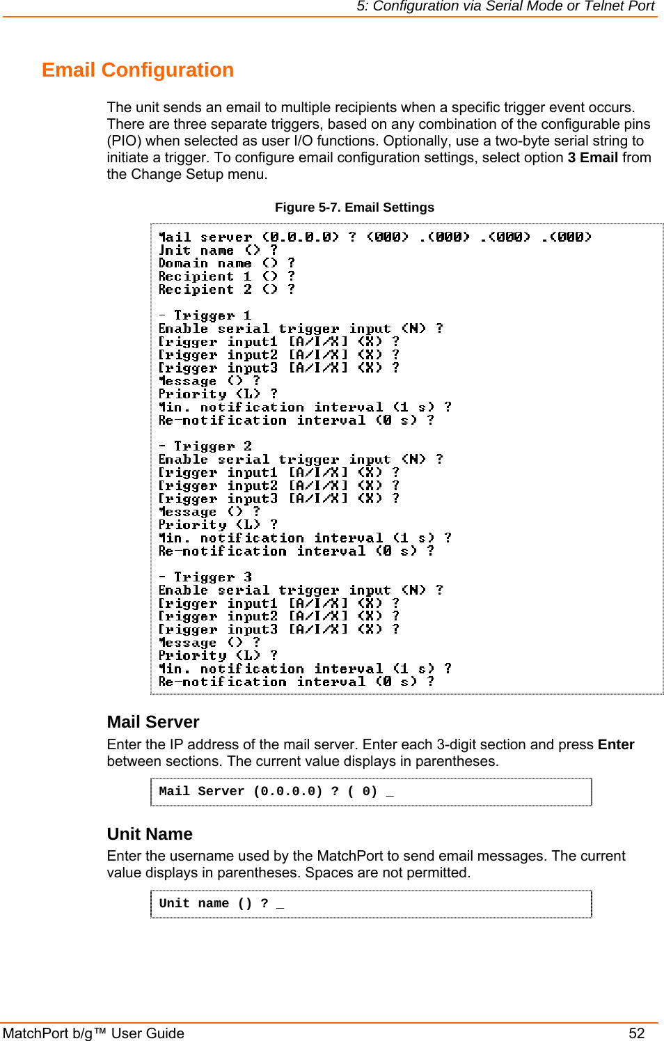
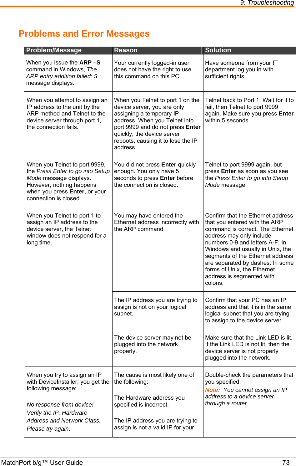
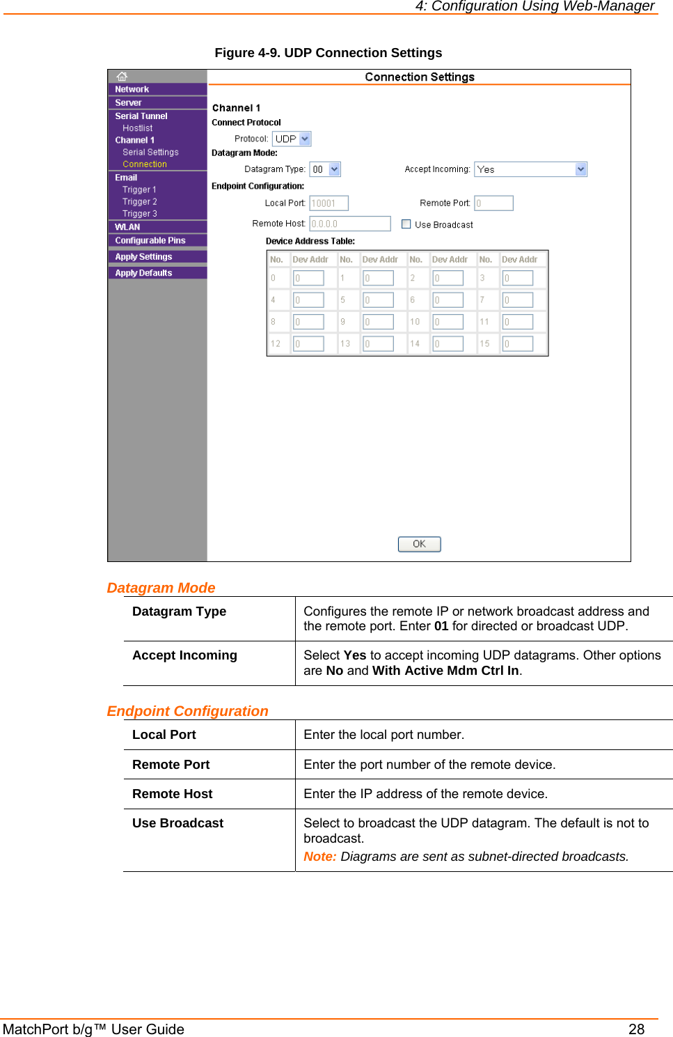
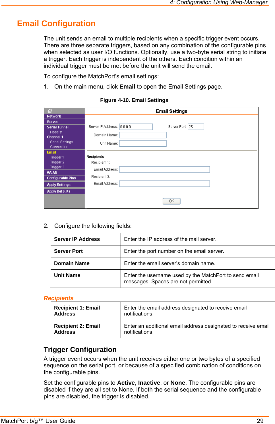
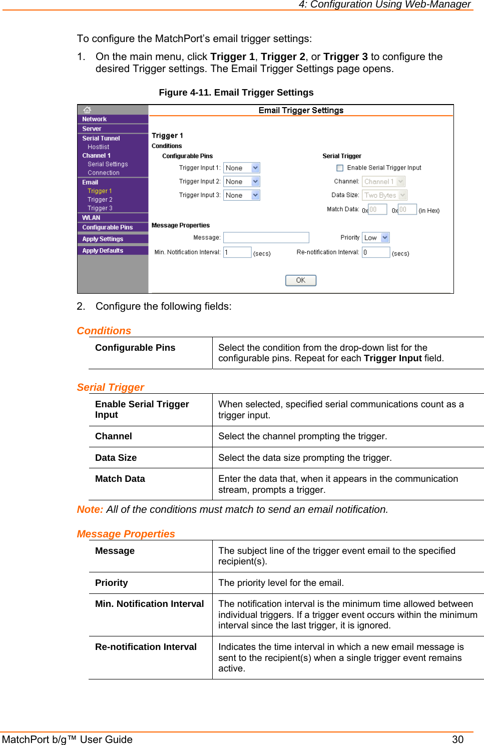
![5: Configuration via Serial Mode or Telnet Port MatchPort b/g™ User Guide 53 Domain Name Enter the email server’s domain name. The current value displays in parentheses. Domain name () ? _ Recipients Enter the full email address of up to two trigger email recipients. The current value displays in parentheses. Recipient 1 () ? _ Recipient 2 () ? _ Triggers A trigger event occurs when the unit receives the specified trigger input because of a specified combination of conditions on the configurable pins. Enable serial trigger input (N) ? Trigger input1 [A/I/X] (X) ? Trigger input1 [A/I/X] (X) ? Trigger input1 [A/I/X] (X) ? Message () ? Priority (L) ? Minimum notification interval (1 s) ? Re-notification interval (0 s) ? To change the configurable pins’ settings, send setup records to Port 77FE. Enable serial trigger input Select (Y) Yes to enable serial trigger inputs. Trigger inputs 1-3 Set the configurable pins to A = Active, I = Inactive, or X = Don’t Care. Active can mean Active Low or Active High. If the configurable pins are all set to X (Don’t Care), then they are disabled. If both the serial sequence and the configurable pins are disabled, the trigger is disabled. Note: Each trigger is independent of the others. Each condition within an individual trigger must be met before the unit will send the email. Message Subject line of the trigger event email to the specified recipient(s). Priority Priority level for the trigger event email. Enter L for normal priority or H for high priority. Minimum notification interval Minimum time allowed between individual triggers. If a trigger event occurs within the minimum interval since the last trigger, it is ignored. Re-notification interval Time interval in which a new email message is sent to the recipient(s) when a single trigger event remains active.](https://usermanual.wiki/Lantronix/MTCHDRCT/User-Guide-801310-Page-53.png)
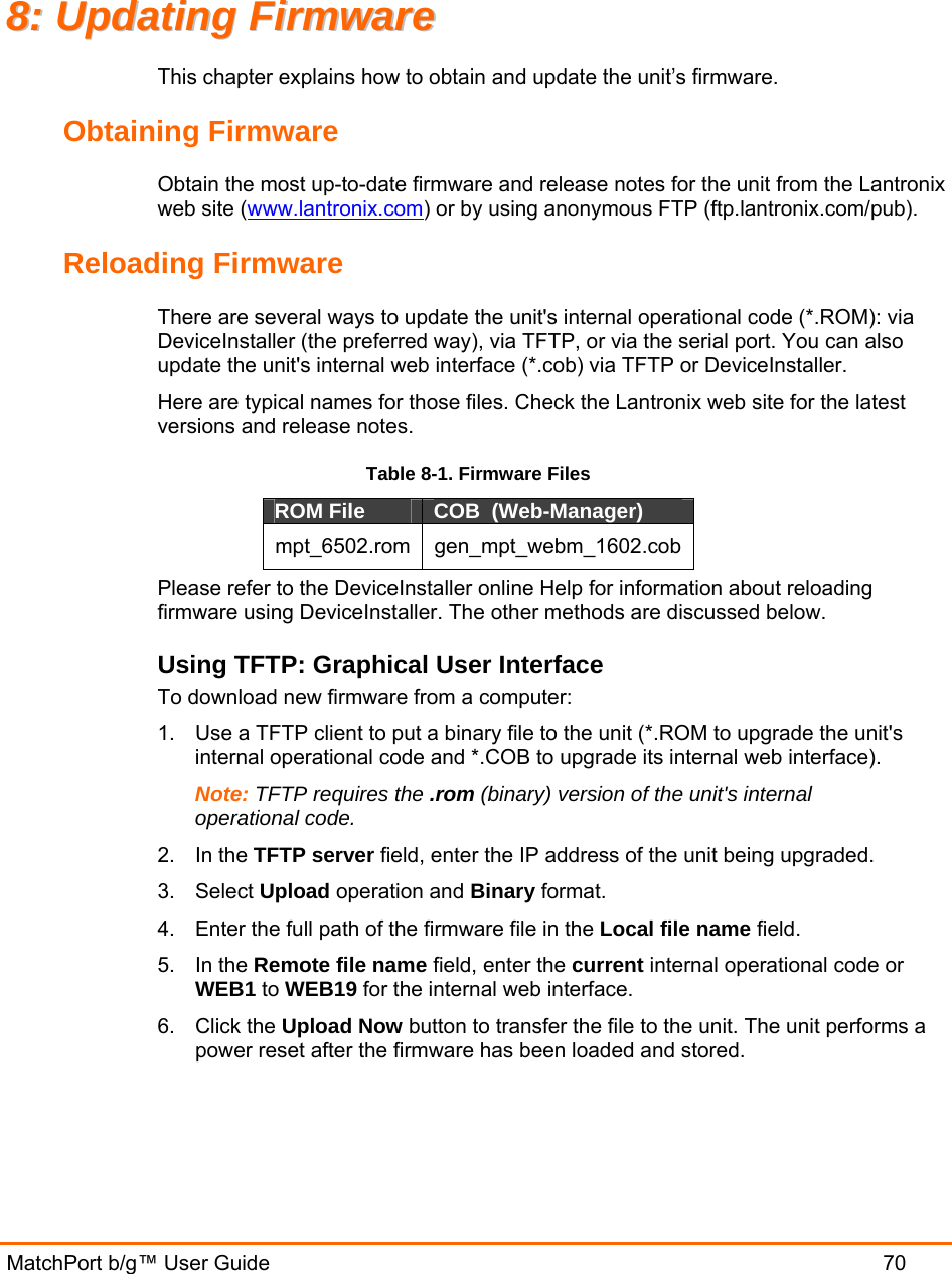
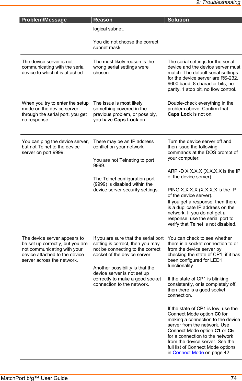
![5: Configuration via Serial Mode or Telnet Port MatchPort b/g™ User Guide 54 WLAN Settings Without adequate protection, a wireless LAN is susceptible to access by unauthorized users. As such, MatchPort features the WPA security standard, based on IEEE802.11i and IEEE802.1X. WEP provides for backwards compatibility and interaction with older devices. When in WPA and WPA2-PERSONAL modes, the encryption setting denotes the lowest acceptable encryption method. CCMP is higher than TKIP and TKIP is higher than WEP. For example, if the MatchPort is configured for WEP and the access point supports TKIP, the negotiation results the use of TKIP. If the MatchPort is configured for TKIP and the access point supports only WEP, the association will fail since the access point does not meet the MatchPort’s requirements. Unicast communication occurs between the access point and a single wireless device. It uses the pairwise encryption method. Multicast communication occurs between the access point and multiple wireless devices. It uses the group encryption method. The group encryption for all wireless devices communicating with the same access point must be equal to receive broadcast and multicast messages. If any device is WEP-only (no support for WPA), set the encryption to TKIP+WEP. To use higher security with the MatchPort than other devices connecting to the same access point, use a group encryption lower than the pairwise encryption. Note: Due to regulations, the country-specific setting has been removed from the setup menu and Web-Manager. However, we provide a separate utility for changing the Country/Zone setting. The utility is called SetZone and is included in the MatchPort package. It is also available for download from the Lantronix web site. The syntax is SetZone <IP address> [<zone abbreviation>] Leaving the zone blank causes the utility to report the current setting only. Following are valid zone abbreviations. These settings are consistent with IEEE802.11b/g zones: US=United States CA=Canada FR=France SP=Spain JP=Japan OT=Others, such as Europe (excluding France), Asia, Africa, and Australia To modify WLAN settings, select 4 WLAN from the Change Setup menu. Topology Select Infrastructure (ESS) mode or Adhoc (IBSS) mode. Infrastructure mode communicates with Access Points. Adhoc mode communicates only with other clients. Topology 0=Infrastructure, 1=Adhoc (0) ? _ Network Name (SSID) Enter the name of the network to which the MatchPort will connect. Network name (LTRX_IBSS) ? _](https://usermanual.wiki/Lantronix/MTCHDRCT/User-Guide-801310-Page-54.png)