File info: application/pdf · 18 pages · 1.36MB
Fire control panel (19, modular)
A6V10275515 h en -- Building Technologies 2018-09-28 Control Products and Systems Sinteso™ Fire control panel (19", modular) FC2080 Individually configurable, modular fire control panel without integrated operating…
[PDF] Fire control panel (19", modular)
Sep 28, 2018 · FCC2002-A1 Basic module incl. 1x CPU card and 1x communication ... FN2012-A1. Ethernet switch (modular). 0.600 kg. S54400-B152-A1. VN2002 ...
Full PDF Document

If the inline viewer fails, it will open the original document in compatibility mode automatically. You can also open the file directly.
Extracted Text
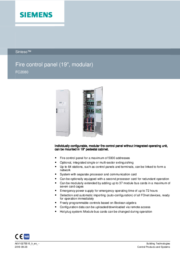
SintesoTM
Fire control panel (19", modular)
FC2080

Individually configurable, modular fire control panel without integrated operating unit, can be mounted in 19" pedestal cabinet.
 Fire control panel for a maximum of 5000 addresses  Optional, integrated single or multi-sector extinguishing  Up to 64 stations, such as control panels and terminals, can be linked to form a
network  System with separate processor and communication card  Can be optionally equipped with a second processor card for redundant operation  Can be modularly extended by adding up to 37 module bus cards in a maximum of
seven card cages  Emergency power supply for emergency operating time of up to 72 hours  Detection and automatic importing (auto-configuration) of all FDnet devices, ready
for operation immediately  Freely programmable controls based on Boolean algebra  Configuration data can be uploaded/downloaded via remote access  Hot plug system: Module bus cards can be changed during operation

A6V10275515_h_en_-2018-09-28

Building Technologies Control Products and Systems

Features and Functions System
The diagrams have been simplified and do not include additional network hardware or security components. Permissible applications are described in the A6V101039125 Network Security Guidelines document. Contact your Siemens IT security expert for more information.
System overview

System overview
2 Building Technologies Fire Safety

A6V10275515_h_en_-2018-09-28

1

Remote access with SintesoView/ Sinteso Touch

2

FS cloud applications

3

Customer network

4

Management platform

5

Remote access to management platform

6

Remote access with Sinteso Mobile

7

Router + Firewall + Virtual Private Network

8

Fire damper with actuator

Transmission of a fault signal

Transmission of an alarm signal

You will find a detailed labeled version of the diagram above along with further information in the A6V10906627 planning guide, see chapter 'Product documentation'.
Optional module bus cards for card cage

Type FCL2001-A1

Designation Line card (FDnet/C-NET)

FCL2002-A1 Line card (collective)

FCL2003-A1 Line card (MS9i)

FCL2005-A1 Line card (AnalogPLUS)

FCL2006-A1 Line card (interactive)

FCL2007-A1 FCI2007-A1 FCI2008-A1

Line card (interactive, Ex) I/O card (RT) I/O card (programmable)

FCI2009-A1 I/O card (horn/monitored)

Properties
4x loops each with 252 addresses, max. of 252 addresses per line card
8x lines each with a maximum of 32 devices
2x loops each with a maximum of 50 addresses, max. 100 addresses
4x loops each with a maximum of 128 addresses, max. of 512 addresses per line card
1x loop with max. 128 devices or 1 stub with 32 devices
1x stub with max. 32 devices
Outputs for alarm, fault, local alarm
12x freely programmable inputs/outputs per I/O card
8x monitored horn outputs or monitored outputs

Mixed usage is possible with a maximum of 5000 addresses per control panel.

Building Technologies Fire Safety

3 A6V10275515_h_en_--
2018-09-28

Networking of fire control panels
The diagrams have been simplified and do not include additional network hardware or security components. Permissible applications are described in the A6V101039125 Network Security Guidelines document. Contact your Siemens IT security expert for more information.
Up to 32 control panels and terminals can be linked to form one FCnet network. If the FCnet network is connected to a danger management system via BACnet, up to 16 control panels and terminals can be networked.

Sub-net

1

Management platform

2

Remote access to management platform

Transmission of a fault signal

Transmission of an alarm signal

4 Building Technologies Fire Safety

A6V10275515_h_en_-2018-09-28

An optical FCnet/LAN network allows up to 14 sub-nets with up to 16 stations to be operated in one network. A maximum of 64 stations is supported in total.

Backbone

1

Remote access with SintesoView/ Sinteso Touch

2

FS cloud applications

3

Customer network

4

Management platform

5

Remote access to management platform

6

Remote access with Sinteso Mobile

7

Router + Firewall + Virtual Private Network

Transmission of a fault signal

Transmission of an alarm signal

You will find a detailed labeled version of the diagram above along with further information in the A6V10906627 planning guide, see chapter 'Product documentation'.

Building Technologies Fire Safety

5 A6V10275515_h_en_--
2018-09-28

Control panels
General features and functions  System with multiple redundancy  Optionally available with redundant main processor  Automatic recognition and addressing of module bus cards  Turbo isolation in the event of a short-circuit to ensure uninterrupted availability of FD20
devices  Processes signals from Sinteso as well as from earlier detector series  Siemens danger management system can be connected  Supplied with the following pre-fitted interfaces:
� 2x integrated FCnet interfaces � 1x separate Ethernet connection on CPU card for SintesoWorks � 4x Ethernet connections on a communication card, one of which features ground
fault monitoring � Integrated RS485 and RS232 serial interface  Floor repeater terminals, alarm devices, and mimic displays supplied with power via detector line (FDnet)  Modular energy supply concept that relies on a maximum of two power supply modules with up to three 150 W power supplies; card cages can be connected to power supply modules however you like  Separate batteries for each power supply module  Control and operation via other control panels on the network  An operating unit with up to two operating add-ons can be optionally installed; operated as a separate fire terminal  Mixed use of all module bus cards (line and I/O cards) possible.  Integrated degraded mode function  Freely configurable, time-dependent controls with optional weekly switching programs  Time and situation-dependent changeover of detector parameter sets  Controls for synchronous activation of sounders / sounder bases with signal sound, flash, and voice output  The control panel and the fire detection system are custom-configured using the 'SintesoWorks' software  Firmware for all processor-controlled control panel components can be updated  Customer texts can be adapted directly on the operating unit of the control panel or with the 'SintesoWorks' software  Up to 13000 events can be called up from the event memory and filtered based on various criteria  Automatic summer/normal time changeover

6 Building Technologies Fire Safety

A6V10275515_h_en_-2018-09-28

FH2080-AA

Control panel-specific features
Housing (19" pedestal cabinet)
 5000 addresses  30...240 lines (depending on line card and configuration)  Max. 2 power supply units at 300 W; can be extended to 450 W  Max. battery capacity 100 Ah per power supply unit  Max. 7 card cages for module bus cards  Max. 5 module bus cards per card cage  Max. 37 module bus cards  Max. 8 flooding zones; max. 16 flooding zones with additional 19" pedestal
cabinet

FCC2002-A1

Features of the basic components
Processor unit (19", FC2080)
 Basic component for the FC2080  Already pre-mounted in the housing (19", pedestal cabinet) FH2080-AA  Incl. cable kit for connecting an optional operating unit  Includes 19" carrier with cable duct, a card cage (CPU), and a card cage (5
slots)  Incl. a CPU card (FC2080) and communication card (FC2080)  One slot in the card cage (CPU) is reserved for a redundant CPU card
(FC2080)  Two slots in the card cage (CPU) are reserved for module bus cards

FHA2022-A1

Carrier (19", power supply)
 Basic component for the fire control panel FC2080  Guarantees the required energy supply.  Mounted on the side wall of the 19" pedestal housing FH2080-AA.  Installation of a second power supply unit with separate battery kit possible  Consists of the following elements:
� One carrier plate with DIN rails and cable ducts � 2 power supplies (150 W), connected in parallel for 300 W � One terminal strip for the primary supply � One terminal strip for the secondary supply � One free position for a third power supply that can be connected in
parallel (150 W)

Building Technologies Fire Safety

7 A6V10275515_h_en_--
2018-09-28

Extensions

You will find information on the integrated extinguishing system and the individual extinguishing components that are available in a separate data sheet with the document ID 'A6V11480005'.

FCA2008-A1

Card cage (5 slots)
 For installation in fire control panel FC2080  For holding a maximum of 5 module bus cards  Also requires the carrier (19", card cage) FHA2023 as a mounting support  Max. 2 card cages can be mounted to the mounting support

FCC2004-A1 FCM2028-A2

CPU card (FC2080)  Optional second CPU card for extension to redundant CPU operation of the
fire control panel FC2080  Inserted in the free slot of the card cage (CPU)
Operating unit  Optional standard operating unit for the fire control panel FC2080  From a configuration perspective, this is considered as a separate station
FT2040 and has the same functions

FCM2030-C2 FCM2037-A2

Operating unit (+FBA term.)  Optional operating unit with FBA terminal for Switzerland for the fire control
panel FC2080  From a configuration perspective, this is considered as a separate station
FT2040 and has the same functions
Operating unit (+LED indicator)  Optional operating unit with 24x LED groups for the fire control panel FC2080  From a configuration perspective, this is considered as a separate station
FT2040 and has the same functions

8 Building Technologies Fire Safety

A6V10275515_h_en_-2018-09-28

FCM2036-A2 FCM2038-A2 FTO2001-A1 DL3750+

Operating add-on (4xLED indicator)  Optional operating add-on with 96 indicator groups with one red/green + one
yellow LED each
Operating add-on (2xLED indicator)  Optional operating add-on with 48 indicator groups with one red/green + one
yellow LED each
Event printer  Thermal printer for installation in operating units or operating add-ons  Can be controlled via the RS232 module FCA2001-A1 (order separately)  Logs all important events, such as alarms, faults, isolations, and test functions
Matrix printer (external)  External matrix printer recommended by Siemens  Supports monitoring for printing faults  Can be controlled via the RS232 module FCA2001-A1 (order separately)  Can be controlled via Ethernet via the print server PS104 from SEH

Building Technologies Fire Safety

9 A6V10275515_h_en_--
2018-09-28

Use
This fire control panel is ideal for large applications with high redundancy requirements, such as airports, power generation facilities, and systems with extinguishing systems.
Within the context of modernization, the Station allows a gradual and seamless transition from older systems to Sinteso.

Design

Function elements
Processor unit The basic module of the FC2080 is delivered pre-mounted on a 19" carrier. It includes a CPU with a main processor on the CPU card (FC2080), a communication card (FC2080), and slots for an optional second CPU card, as well as two slots for any module bus cards. In the card cage (five slots), which is mounted on the same 19" carrier, five additional module bus cards can be installed.
Power supply The power supply feeds the hardware and charges the batteries. In the event of a power cut, the batteries provide emergency current. A maximum of two independent circuits can be operated with their own emergency batteries. Each power supply module has two 150 W power supplies connected in parallel and can be extended by adding an additional 150 W power supply.
Card cage Up to six additional card cages can be mounted for inserting up to five module bus cards.
Module bus cards Line cards for incorporating peripheral devices or I/O cards for fire controls and integration with other systems.
19" carrier 19" carriers can be used to mount card cages, power supplies, batteries, and options inside the 19" housing.
Housing The housing consists of a 19" pedestal cabinet with a base that can accommodate FC2080 components. The housing is supplied with pre-fitted cable ducts and a cabinet door with cut-outs for accommodating the operating unit and operating add-ons. There are various support components for mounting electrical modules in accordance with your individual requirements.
Operating unit and operating add-ons The operating unit and operating add-ons are optional and are installed in the door of the FC2080 pedestal cabinet. They have the function of a separate station.
Configuration The following software allows the system to be customized:  SintesoWorks

Operation

The control panel can be operated via a FT2040 or FT2080 (Touch) operating terminal. The operating terminal can be integrated into the cabinet door or operated remotely. The FC2080 can also be operated via another FS20 control panel on the network.
You will find details and more information in product data sheet 009386.

10 Building Technologies Fire Safety

A6V10275515_h_en_-2018-09-28

Setup

Layout of FC2080

Position Designation

Basic equipment

1

Housing (19" pedestal cabinet)

2

Processor unit (19", FC2080)

3

2x free slots for module bus cards

4

5x slots for module bus cards

5

Carrier (19", power supply)

Extensions

(2)

CPU card (FC2080)

6

Power supply kit (150 W, B)

7

Carrier (19", card cage)

Type FH2080-AA FCC2002-A1
FHA2022-A1 FCC2004-A1 FP2005-A1 FHA2023-A1

Comment
19" pedestal cabinet for accommodating FC2080 components
Basic module incl. 1x CPU card and 1x communication card (FC2080), 2x network modules, and 1x card cage (5 slots)
In card cage (CPU) of processor unit to allow extension through the addition of any two module bus cards
In card cage (5 slots) of processor unit to allow extension through the addition of any five module bus cards
Power supply module incl. 2x 150 W power supplies
For extension to redundant CPU operation
For extension as a 3rd power supply operating in parallel
For mounting a maximum of two card cages or other modules in the 19" cabinet

Building Technologies Fire Safety

11 A6V10275515_h_en_--
2018-09-28

Position 8 9 10 11
12 13 14 15
16 17 18 19 + 20 21

Designation Card cage (5 slots)

Type FCA2008-A1

Carrier (19", power supply)

FHA2022-A1

Carrier (19", option)

FHA2024-A1

Module bus cards: Line card (FDnet/C-NET)

FCL2001-A1

Line card (collective)

FCL2002-A1

Line card (MS9i)

FCL2003-A1

Line card (AnalogPLUS) Line card (interactive) Line card (interactive, Ex) I/O card (RT) I/O card (programmable) I/O card (horn/monitored) Key safe adapter

FCL2005-A1 FCL2006-A1 FCL2007-A1 FCI2007-A1 FCI2008-A1 FCI2009-A1 SDA 3000

Battery (12 V, 65 Ah, VdS) Battery (12 V, 100 Ah, VdS) Battery tray (19")

FA2008-A1 FA2009-A1 FHA2021-A1

Optional operating unit

Operating unit

FCM2028-A2

Operating unit (+ LED indicator) FCM2037-A2

Operating unit (+ Nord. key switch) FCM2028-B2

Operating unit (+ EVAC term.)

FCM2030-N2

Operating unit

FCM2028-F2

Operating unit (+ FBA terminal) FCM2030-C2

Event printer (internal)

FTO2001-A1

Event printer (external)

DL3750+

License key Sx

FCA20xx

Key switch (Kaba)

FTO2005-C1

Key switch (nordic)

FTO2006-B1

Optional operating add-ons:

Operating add-on (2xLED indicator) FCM2038-A1

Operating add-on (4xLED indicator) FCM2036-A1

Plan compartment A3

--

Comment For mounting on carrier (19", card cage) to allow extension through the addition of any five module bus cards For use as an additional 2nd power supply module with separate batteries For mounting options (e.g., FDCIOxxx, relays) in the 19" cabinet
For four FDnet lines (max. 252 addresses per card) For eight MS7/9/24, DS11, Synova 600, SIGMACON collective lines For two addressable MS9i detector lines (max. 100 addresses) For four addressed AnalogPLUS lines For one addressed interactive line For one addressed interactive Ex line For transmission of alarms and faults Twelve programmable inputs/outputs Eight sounders For controlling the fire brigade key depot (available from IFAM) For the emergency power supply
For holding batteries inside 19" cabinet, max. of two per cabinet
Standard operating unit Operating unit with 24x LED groups Operating unit with key switch (nordic) Operating unit incl. 10x evacuation zones Operating unit for France only Operating unit for Switzerland only For logging system events
For special functions For operating access authorization
Maximum of 2 operating add-ons per FC2080 With 2 LED modules With 4 LED modules Installed in door

12 Building Technologies Fire Safety

A6V10275515_h_en_-2018-09-28

Type Overview

Housing

Type Order number Number of FDnet addresses Lines
Power supply Max. battery capacity Number of module bus cards in the card cage Total number of module bus cards

FH2080-AA S54400-C103-A1
5000 30...240 (depending on line card and configuration) Max. 2x 450 W Max. 2x 12 V, 100 Ah Max. 5
Max. 37

Building Technologies Fire Safety

13 A6V10275515_h_en_--
2018-09-28

Details for ordering

Basic equipment

Type FH2080-AA FCC2002-A1
FHA2022-A1

Designation

Weight

Housing (19" pedestal cabinet) 120.000 kg

Processor unit (19", FC2080) incl. 4.600 kg CPU card (FC2080) and communication card (FC2080)

Carrier (19", power supply)

1.600 kg

Order number S54400-C103-A1 S54400-B17-A1
S54400-B24-A1

Extensions
You will find information on the integrated extinguishing system and the individual extinguishing components that are available in a separate data sheet with the document ID 'A6V11480005'.

Type FCA2008-A1 FCC2004-A1 FCI2007-A1 FCI2008-A1 FCI2009-A1 FCL2001-A1 FCL2002-A1 FCL2003-A1 FCL2005-A1 FCL2006-A1 FCL2007-A1 FCM2028-A2 FCM2028-B2 FCM2028-F2 FCM2030-C2 FCM2030-N2 FCM2036-A2
FCM2037-A2 FCM2038-A2
FHA2007-A1 FHA2021-A1 FHA2023-A1 FHA2024-A1 FN2006-A1

Designation

Weight

Card cage (5 slots)

1.479 kg

CPU card (FC2080)

0.200 kg

I/O card (RT)

0.111 kg

I/O card (programmable)

0.097 kg

I/O card (horn, monitored)

0.109 kg

Line card (FDnet/C-NET)

0.119 kg

Line card (collective)

0.117 kg

Line card (MS9i)

0.115 kg

Line card (AnalogPLUS)

0.120 kg

Line card (interactive)

0.117 kg

Line card (interactive, Ex)

0.117 kg

Operating unit

2.392 kg

Operating unit (+nord. key switch) 2.441 kg

Operating unit (FR)

2.413 kg

Operating unit (+FBA terminal) 2.568 kg

Operating unit (+EVAC terminal) 2.569 kg

Operating add-on (4xLED indicator)

3.905 kg

Operating unit (+LED indicator) 2.506 kg

Operating add-on (2xLED indicator)

2.516 kg

Mounting plate

0.800 kg

Battery tray (19")

2.000 kg

Carrier (19", card cage)

1.600 kg

Carrier (19", option)

1.600 kg

Fiber network module (SM)

0.792 kg

Order number S54400-B28-A1 S54400-A18-A1 S54400-A20-A1 S54400-A6-A1 S54400-A21-A1 A5Q00009875 A5Q00010502 A5Q00010044 S54400-A107-A1 S54400-A108-A1 S54400-A134-A1 S54400-F83-A1 S54400-F83-A2 S54400-F83-A3 S54400-F93-A1 S54400-F93-A2 S54400-B147-A1
S54400-B148-A1 S54400-B146-A1
A5Q00010151 S54400-B23-A1 S54400-B25-A1 S54400-B26-A1 S54400-A109-A1

14 Building Technologies Fire Safety

A6V10275515_h_en_-2018-09-28

Type FN2007-A1 FTO2001-A1 FTO2005-C1 FTO2006-B1 SDA3000

Designation Fiber network module (MM) Event printer Spare printer reels (10 reels) Key switch (Kaba) Key switch (nordic) Key safe adapter

Weight 0.792 kg 0.141 kg 0.090 kg 0.083 kg 0.046 kg 1.500 kg

Order number S54400-A110-A1 A5Q00010126 A5Q00017619 A5Q00010113 A5Q00010129 9102.0648

Auxiliary power supply

Type FHA2022-A1 FP2005-A1

Designation
Carrier (19", power supply)
Power supply kit (150 W, B) for extension

Weight 1.600 kg 1.181 kg

Order number S54400-B24-A1 A5Q00018779

Network (backbone)

Type FCA2031-A1

Designation Connection module (MoNet)

FHA2029-A1 FN2012-A1 VN2002-A1 VN2003-A1

Mounting kit (switch) Ethernet switch (modular) Ethernet module (MM) Ethernet module (SM)

Weight 0.081 kg incl. cable 1.261 kg 0.600 kg 0.026 kg 0.026 kg

Order number S54400-A153-A1
S54400-B79-A1 S54400-B152-A1 S54400-A43-A1 S54400-A44-A1

Batteries

Type FA2008-A1 FA2009-A1 FHA2061-A1

Designation Battery (12 V, 65 Ah, VdS) Battery (12 V, 100 Ah, VdS) Mounting kit (batteries)

Weight 21.300 kg 32.000 kg

Order number A5Q00019357 A5Q00023101 S54400-B91-A1

License keys
Type FCA2033-A1 FCA2034-A1 FCA2035-A1 FCA2036-A1

Designation License key (S1) License key (S2) License key (S3) License key (S4)

Weight 0.010 kg 0.010 kg 0.010 kg 0.010 kg

Order number S54400-P154-A1 S54400-P155-A1 S54400-P156-A1 S54400-P157-A1

External printer

Type DL3750+ -

Designation
Matrix printer (external)
Color ribbon for matrix printer DL3750+

Weight 7.300 kg 0.078 kg

Order number A5Q00023962 A5Q00023963

Building Technologies Fire Safety

15 A6V10275515_h_en_--
2018-09-28

Product documentation

Title

Document ID

System documentation

System description

008836

Product data

008837

Planning

008843

Mounting/Installation

008851

Data sheets

FC2020 - fire control panel

009383

FC2030 - fire control panel for modernization A6V10087532

FC2040 - fire control panel

009384

FC2060 - fire control panel (modular)

A6V10087844

FC2080 - fire control panel (19", modular) A6V10275515

FT2040 - fire terminal

009386

FT2080 - fire terminal (Touch)

A6V10378271

Fire detection system with integrated single A6V11480005 or multi-sector extinguishing

Network Security Guidelines

A6V101039125

Planning overview

A6V10906627

Related documents such as environmental declarations, CE declarations, etc., can be downloaded at the following Internet address:
http://siemens.com/bt/download

Guarantee

Technical data on specific applications are valid only together with Siemens products listed under "Equipment combinations". Siemens rejects any and all warranties in the event that third-party products are used.

16 Building Technologies Fire Safety

A6V10275515_h_en_-2018-09-28

Technical data

FC2080 inside 19" housing

Supply

Mains voltage

AC 115/230 V +10/-15 %

Power supply

>150 W

Operating voltage

DC 21...28.4 V

Operating current

>3 A

Battery capacity

2x 12 V, max. 100 Ah

Battery monitoring

Yes

Network monitoring

Yes

Inputs / outputs

Connectable detector series

Sinteso, collective, MS9i, DS11

Number of addresses

Max. 5000

Number of lines in the maximum configuration:

 FDnet (4 per line card)

Max. 120

 Collective (8 per line card)

Max. 240

 MS9i (2 per line card)

Max. 60

 Interactive (1 per line card)

Max. 30

 Interactive, Ex (1 per line card)

Max. 30

 AnalogPLUS (4 per line card)

Max. 120

Input/output cards:

 I/Os (programmable)

12 per FCI2008-A1

 I/Os (horn)

8 per FCI2009-A1

 I/Os (RT):

RT alarm (monitored and relay)

1 + 1 per FCI2007-A1

RT fault (monitored and relay)

1 + 1 per FCI2007-A1

Local alarm

1 per FCI2007-A1

Interfaces

Operating unit

optional

RS232, RS485 serial interfaces

1 + 1 (integrated)

Slots for network modules (on CPU and 1 per FCC2004-A1 (Main)

COM cards)

1 per FCC2005-A1 (Degrade)

Slots for module bus cards

Max. 37

Ethernet port RJ45

3

Ambient conditions

Operating temperature

-8...+42 �C

Storage temperature

-20...+60 �C

Air humidity (no condensation permitted)

 95% rel.

Maximum height above sea level

3700 m

Building Technologies Fire Safety

17 A6V10275515_h_en_--
2018-09-28

FC2080 inside 19" housing Mechanical data Dimensions (W x H x D): Pedestal cabinet incl. base Protection category (IEC 60529) Color Standards and approvals VdS Standards

600 x 2200 x 600 mm IP30 ~RAL 7035 light gray
G212027 EN 54-2, EN 54-4, VdS 2095

12

0786

FC2080

Siemens Schweiz AG; Theilerstrasse 1a CH-6300 Zug
Technical data: see doc. 008836

FC2080 - Control and Indicating Equipment incl. SV24V150W - 150W/24VDC Power Supply Equipment for use in fire detection and fire alarm systems installed in buildings.

305/2011/EU (CPR): EN 54-2 / EN 54-4 ; 2014/30/EU (EMC): EN 50130-4 / EN 61000-6-3 ; 2014/35/EU (LVD): EN 60950-1 ; 2011/65/EU (RoHS): EN 50581

The declared performance and conformity can be seen in the Declaration of Performance (DoP) and the EU Declaration of Conformity (DoC), which is obtainable via the Customer Support Center: Tel. +49 89 9221-8000 or https://siemens.com/bt/download

DoP No.: 0786-CPR-21148; DoC No.: CED-FC2080

13

0786

SV24V150W

Siemens Schweiz AG; Theilerstrasse 1a CH-6300 Zug
Sinteso technical data: see doc. 008837 CerberusTM PRO technical data: see doc. A6V10210368

SV24V150W - Power Supply Equipment 24VDC/150W for use in fire detection and fire alarm systems installed in buildings.

305/2011/EU (CPR): EN 54-4 ; 2014/30/EU (EMC): EN 50130-4 / EN 61000-6-3 ; 2014/35/EU (LVD): EN 60950-1 ; 2011/65/EU (RoHS): EN 50581

The declared performance and conformity can be seen in the Declaration of Performance (DoP) and the EU Declaration of Conformity (DoC), which is obtainable via the Customer Support center: Tel. +49 89 9221-8000 or http://siemens.com/bt/download

DoP No.: 0786-CPD-20775; DoC No.: CED-SV24V150W

Issued by Siemens Switzerland Ltd Building Technologies Division International Headquarters Theilerstrasse 1a CH-6300 Zug Tel. +41 58 724 2424 www.siemens.com/buildingtechnologies

18

Building Technologies

Fire Safety Document ID

A6V10275515_h_en_--

Edition

2018-09-28

� Siemens Switzerland Ltd, 2011 Technical specifications and availability subject to change without notice.
A6V10275515_h_en_-2018-09-28 FS20