File info: application/pdf · 4 pages · 308.28KB
16
Product Specification VIBROCONTROL 1800 Series
2021-07-17 —
[PDF] Product Specification VIBROCONTROL 1800 Seriesassets.omega.com › spec › VC1800...
Data Sheet (PDF)
Brüel & Kjaer acceleration sensors vibration monitoring system
Full PDF Document

If the inline viewer fails, it will open the original document in compatibility mode automatically. You can also open the file directly.
Extracted Text
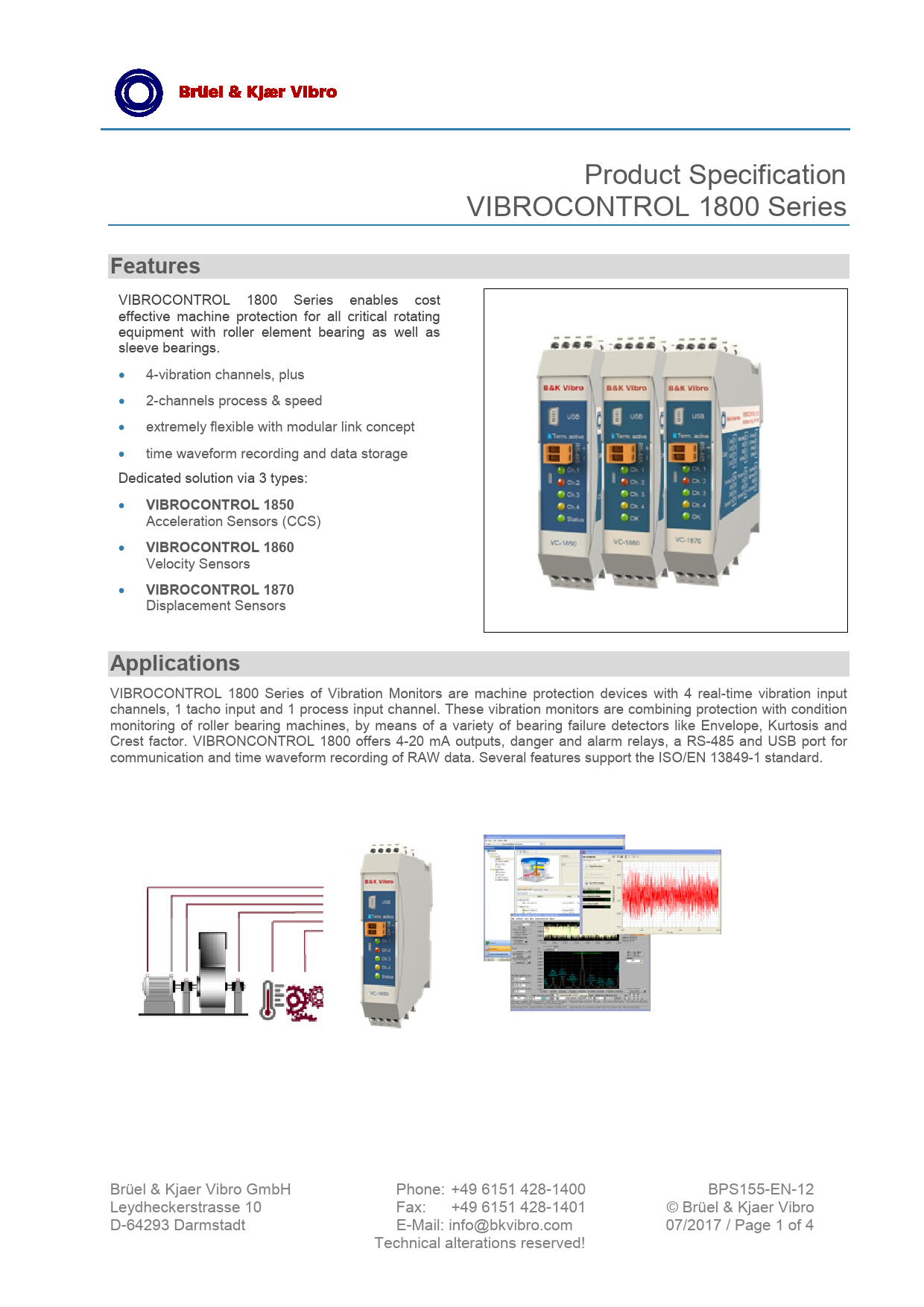
Product Specification VIBROCONTROL 1800 Series
Features
VIBROCONTROL 1800 Series enables cost effective machine protection for all critical rotating equipment with roller element bearing as well as sleeve bearings.
� 4-vibration channels, plus
� 2-channels process & speed
� extremely flexible with modular link concept
� time waveform recording and data storage Dedicated solution via 3 types:
� VIBROCONTROL 1850 Acceleration Sensors (CCS)
� VIBROCONTROL 1860 Velocity Sensors
� VIBROCONTROL 1870 Displacement Sensors
Applications
VIBROCONTROL 1800 Series of Vibration Monitors are machine protection devices with 4 real-time vibration input channels, 1 tacho input and 1 process input channel. These vibration monitors are combining protection with condition monitoring of roller bearing machines, by means of a variety of bearing failure detectors like Envelope, Kurtosis and Crest factor. VIBRONCONTROL 1800 offers 4-20 mA outputs, danger and alarm relays, a RS-485 and USB port for communication and time waveform recording of RAW data. Several features support the ISO/EN 13849-1 standard.

Br�el & Kjaer Vibro GmbH Leydheckerstrasse 10 D-64293 Darmstadt

Phone: +49 6151 428-1400 Fax: +49 6151 428-1401 E-Mail: info@bkvibro.com Technical alterations reserved!

BPS155-EN-12 � Br�el & Kjaer Vibro 07/2017 / Page 1 of 4

Product Specification VIBROCONTROL 1800 Series

EN

Technical Data

6 Input channels:
� 4 configurable vibration sensor inputs: VIBROCONTROL 1850 - accelerometers CCS VIBROCONTROL 1860 - velocity sensors VIBROCONTROL 1870 - displacement sensors
� 1 Input for process data, selectable analogue 4-20 mA, 0-20 mA, 0-22V
� 1 Tacho input for NPN, PNP, AC speed sensor

Sensor types:

� VIBROCONTROL 1850

Accelerometers

10-500 mV/g, type CCS

Maximum input

�5.4 Vpk

Transducer Bias

5 mA

Input Resistance / Impedance  450 k, 10 nF

� VIBROCONTROL 1860

Velocity sensors

50-100 mV/mm/s

Maximum input

�6.0/8.0 Vpk

Input Resistance / Impedance  450 k, 5 nF

� VIBROCONTROL 1870

Displacement sensors

0.8-8 V/mm

Maximum voltage input

-2 to -22 V

Peak detector, attack time

1-1,000 ms

Peak detector, decay time

0.1-100 s

Input Resistance / Impedance  450 k, 10 nF

6 Measurement results per vibration channel:

� 2 Overall vibration values

Detectors

True RMS, Pk-Pk or Pk

Sample rates

4,800 or 24,000 Hz

Filter ranges

0.7 Hz to 10 kHz

Measuring parameter mm/s, m/s2, g, m, mm

� 4 Roller bearing condition units

Detectors

True RMS, 2 Envelope

Filter ranges

1 - 500 Hz

Kurtosis/Crest factor

acc. VDI 3832

Configurable measuring ranges:
� Full scale vibration measuring ranges up to 1-100 mm/s,1-300 m/s2,0.1-15 mm Pk Pk

Standard frequency ranges:

� 10 Hz � 1,000 Hz, -1 dB, 24 dB/oct.

� Selectable ranges e.g. or multiple filters settings

1-300/1,000 Hz 0.7-10,000 Hz

� Filter response High pass and low pass filters; refer to the setup part for the specific parameters for the Cut-off freq., pass band attenuation, Stop band freq. and Stopband attenuation.

Up to 4 configurable outputs:

� 4 Analogue DC outputs

Can be configured as 0/4 - 20 mA, 0/2-10 V,

Each output can be assigned to any of the

measuring parameters.

Voltage load:

min. 10 k

Current load:.

max. 400

or

� 4 Alarm relay drivers

Relay drivers for external coil: With break-

function, can be user configured as Alert or

Danger with latch function or auto reset.

Max voltage

30 V

Max current:

100 mA

Alarm detectors:

� Alert and Danger per each detector with adjust-

able alarm limits.

Alert delay time

0 - 100 s

Danger delay time

0 - 100 s

Reset time for Alert and Danger

0 - 100 s

Up to 24 additional relays: (VIBROCONTROL 1801)

� Up to 2 Relay Modules consisting of 12

galvanic isolated relays each. Alert and Danger

alarms can be directed to these relays.

Max voltage:

30 V

Max current:

100 mA

OK relay:
� 1 galv. isolated redundant relay with breakfunction (power fail-safe). Danger alarms can be forwarded to this relay, when the monitor is configured as a Protection Monitor according to ISO/EN 13849-1. All system failures, like cable short, cable break and internal system failure, will automatically trip the OK- relay.

Measurement accuracy:
� Vibration Measurement �3.5% of reading �0,5% of Full Scale setup, typical, @calibration ref: 100Hz, velocity, 25 C, with current LP and HP filter setup.
� Process Measurement �0.75% of reading �0.5% of Full Scale setup
� Speed sensors �0.5% of reading, Pulse speed 1Hz to 30kHz (RPM depending of pulse per revolutions setup)
� Analogue output �1.5% of reading
�1% of Full Scale

Page 2 of 4

� Br�el & Kjaer Vibro  July 17  BPS0150-EN-12

Product Specification VIBROCONTROL 1800 Series

EN

Test function:
Can be activated digitally or by PC. As default the
alarm relays activate and DC outputs increase to
the specified test level of 102 %.

Time waveform recording:

Up to 4 input channels can record digital raw data

(time waveform) simultaneously to a PC running

"Commpact Analyzer". The recording can be done

through:

RS-485/LAN (buffered)

Up to 10 kHz

Mini USB (real-time)

Up to 10 kHz

Time waveform recording is user activated and con-

tains scalar values for vibration and process input

data at start of recording.

Data storage:
(VIBROCONTROL 1803 /1804) All input channels can be trended and alarms can be stored when connected to either EtherBridge or directly to a PC running "Compact Analyzer". VIBROCONTROL 1804 EtherBridge RAM can store trends and time wave-form recordings event or timer based.

Communication:

RS-485 interface

2 screw terminals

Daisy chain, up to 255 units

USB interface:

Mini USB/B

Remote access through EtherBridge Module

(VIBROCONTROL 1803) is possible.

Link Concept modularity:
VIBROCONTRL 1800 Series �all components Vibration Monitor, EtherBridge, Relay Module, Input and Output Modules can be interconnected by means of DIN rail bus connectors

Front panel:
5 light diodes indicate channel status (green, yellow,
red) for each of the 4 vibration input channels, as
well as for general system status.

Temperature:
� Operating: � Storage:

-10 �C to +50 �C -40 �C to +85 �C

Housing:
DIN rail enclosure IP20 with screw terminals

� Dimensions:

H: 110, W: 23, D: 114 mm

� Weight (measuring module):

160 g

Compliance:
� CE, ISO 13849-1, ISO 10816-3, VDI 3832, API 670

Accessories:
� External Power supply (e.g. AC-4111) +24 V DC, �5 %, max. power consumption; 10 W

� Br�el & Kjaer Vibro  July 17  BPS0150-EN-12

Page 3 of 4

Product Specification VIBROCONTROL 1800 Series

EN

Ordering Information
VIBROCONTROL 1850
Vibration monitoring unit for accelerometer input
Standard Accelerometer AS-062 (CCS)
VIBROCONTROL 1860
Vibration monitoring unit for velocity sensor input
Standard velocity sensor VS-068 (horiz.) or VS-069 (vert.)
VIBROCONTROL 1870
Vibration monitoring unit for displacement sensor input
Please find alternative sensors out of B&K Vibro�s large portfolio.

Order Code: VC-1850 Order Code: AS-062

Order Code: VC-1860

Order Code:

VS-068 VS-069

Order Code: VC-1870

Additional modules within the VIBROCONTROL 1800 series � Link Concept

VIBROCONTROL 1801 Relay Module for DIN Rail installation incl. 12 potential free relays 30V

Order Code: VC-1801

VIBROCONTROL 1803 Ethernet-Bridge incl. RS485, shared RS485/RS232 and LAN

Order Code: VC-1803

VIBROCONTROL 1804 Ethernet-Bridge & Data Logger incl. 4 GB RAM

Order Code: VC-1804

Compact Commander Software for Configuration & Diagnostics

Compact Setup - Configuration Software for all VIBROCONTROL 18xx modules Compact Analyzer - Analyzing Software for stored measuring data

included in delivery on request

Optional: Accessories
Power Supply 24 VDC Type: DSP 10-24; 230VAC / 24 VDC, 10 W
Field Housing for VIBROCONTROL 1800 components Fibox, Polycarbonat AC-2131
Field Housing for VIBROCONTROL 1800 components IP67, Aluminium AC-2132
Field Housing for VIBROCONTROL 1800 components metal AC-2133

Order Code: AC-4111 on request on request on request

� Br�el & Kjaer Vibro  July 17  BPS0150-EN-12

Page 4 of 4