File info: application/pdf · 3 pages · 991.36KB
CEM70 Belt Tension Adjustment - ioptron.com
CEM70 Belt Tension Adjustment Tool need: a set of metric hex keys, a small flat head screwdriver RA Belt Adjustment 1. Set the mount to Zero Position. Locking RA axle by insert the locking Allen wrench.
CEM70 Belt Tension Adjustment Tool need: a set of metric hex keys, a small flat head screwdriver RA Belt Adjustment 1. Set the mount to Zero Position. Locking RA axle by
CEM70 Belt Tension Adjustment
Tool need: a set of metric hex keys, a small flat head screwdriver RA Belt Adjustment 1. Set the mount to Zero Position. Locking RA axle by. insert the locking Allen wrench.
Full PDF Document

If the inline viewer fails, it will open the original document in compatibility mode automatically. You can also open the file directly.
Extracted Text
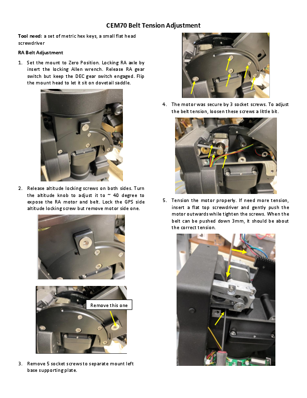
CEM70 Belt Tension Adjustment
Tool need: a set of metric hex keys, a small flat head screwdriver RA Belt Adjustment 1. Set the mount to Zero Position. Locking RA axle by
insert the locking Allen wrench. Release RA gear switch but keep the DEC gear switch engaged. Flip the mount head to let it sit on dovetail saddle.
4. The motor was secure by 3 socket screws. To adjust the belt tension, loosen these screws a little bit.

2. Release altitude locking screws on both sides. Turn the altitude knob to adjust it to ~ 40 degree to expose the RA motor and belt. Lock the GPS side altitude locking screw but remove motor side one.

5. Tension the motor properly. If need more tension, insert a flat top screwdriver and gently push the motor outwards while tighten the screws. When the belt can be pushed down 3mm, it should be about the correct tension.

Remove this one
3. Remove 5 socket screws to separate mount left base supporting plate.

6. When put the side plate back, it needs be very careful not to jam the wires.

And slightly pull the cables to make sure they move freely.

7. Slide the side panel on and arrange the cables to go into the slot.

10. After secure the side cover. Put the altitude locking screws back and lock it.

8. Put 5 screws back and slightly tighten them

9. Remove two screws that hold the RA control board cover to expose the cables that go to the RA board.

DEC Belt Adjustment
1. Rotate the mount in RA to expose the DEC motor cover under the DEC saddle. There are 4 hex head screws hold it in place. One is blocked by the DEC control board cover.
2. Remove two screws that hold the DEC board cover.

5. Slightly release 3 screws that hold the motor on worm assembly. To tighten the belt, gently push the motor outward. Hold the motor while tightening the screws. Check the mount performance before put the cover on.

3. Remove two screws under DEC ring gear compartment.

4. Remove another two on the back.