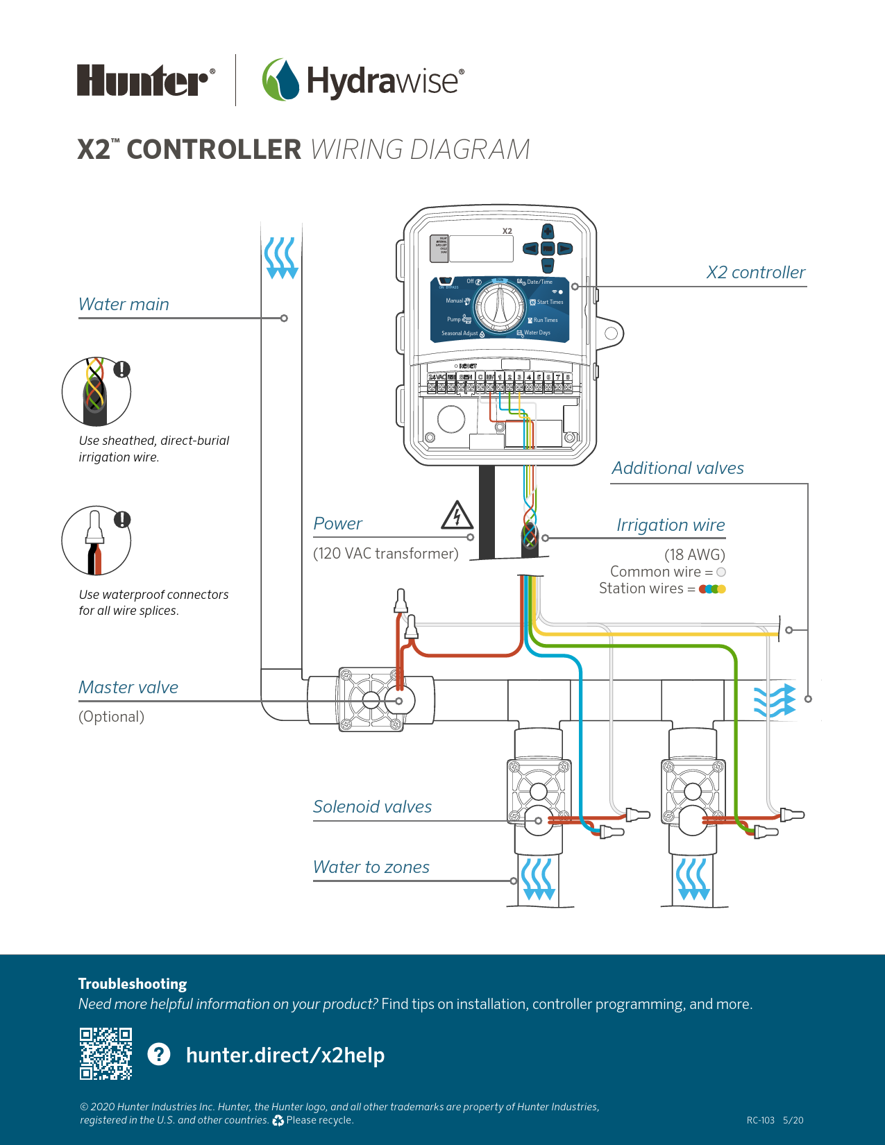
Manual O Seasonal Adjust Pump ON BYPASS X2™ CONTROLLER WIRING DIAGRAM Water main Master valve (Optional) Water to zones Solenoid valves X2 controller Power (120 VAC transformer) Additional valves Irrigation wire (18 AWG) Common wire = Station wires = Use sheathed, direct-burial irrigation wire. Use waterproof connectors for all wire splices ...
Water Days. Manual. O. Seasonal Adjust. Pump. BYPASS. ON. X2™ CONTROLLER WIRING DIAGRAM. Water main. Master valve. (Optional). Water to zones.
X2TM CONTROLLER WIRING DIAGRAM

Water main
Use sheathed, direct-burial irrigation wire.
Use waterproof connectors for all wire splices.
Master valve
(Optional)

X2

O

RUN

ON BYPASS

Manual

Pump Seasonal Adjust

Date/Time
Start Times Run Times Water Days

VAC

X2 controller

Power
(120 VAC transformer)

Additional valves
Irrigation wire
(18 AWG) Common wire = Station wires =

Solenoid valves Water to zones

Troubleshooting Need more helpful information on your product? Find tips on installation, controller programming, and more.
hunter.direct/x2help

© 2020 Hunter Industries Inc. Hunter, the Hunter logo, and all other trademarks are property of Hunter Industries, registered in the U.S. and other countries. Please recycle.

RC-1035/20
Adobe PDF Library 15.0 Adobe InDesign 15.0 (Macintosh)