Analog Devices Inc. LT6370HMS8#TRPBF | LT6370HMS8#TRPBF | ET20207534 | Enrgtech LTD
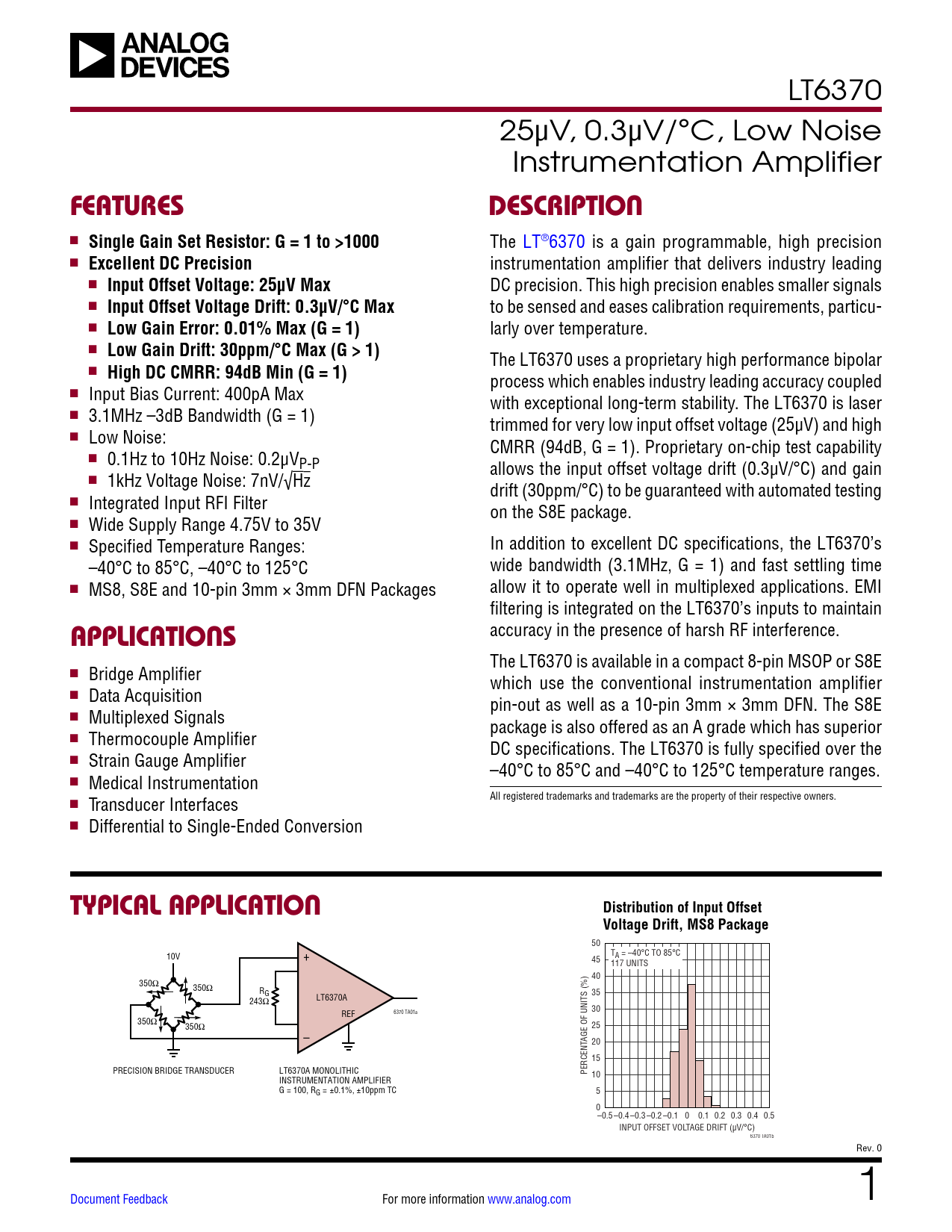
FEATURES nn Single Gain Set Resistor: G = 1 to >1000 nn Excellent DC Precision nn Input Offset Voltage: 25V Max nn Input Offset Voltage Drift: 0.3V/°C Max nn Low Gain Error: 0.01% Max (G = 1) nn Low Gain Drift: 30ppm/°C Max (G > 1) nn High DC CMRR: 94dB Min (G = 1) nn Input Bias Current: 400pA Max nn 3.1MHz 3dB Bandwidth (G = 1) nn Low Noise: nn 0.1Hz to 10Hz Noise: 0.2VP-P nn 1kHz Voltage Noise: 7nV/Hz nn Integrated Input RFI Filter nn Wide Supply Range 4.75V to 35V nn Specified Temperature Ranges: 40°C to 85°C, 40°C to 125°C nn MS8, S8E and 10-pin 3mm × 3mm DFN Packages APPLICATIONS nn Bridge Amplifier nn Data Acquisition nn Multiplexed Signals nn Thermocouple Amplifier nn Strain Gauge Amplifier nn Medical Instrumentation nn Transducer Interfaces nn Differential to Single-Ended Conversion LT6370 25µV, 0.3µV/°C, Low Noise Instrumentation Amplifier DESCRIPTION The LT®6370 is a gain programmable, high precision instrumentation amplifier that delivers industry leading DC precision. This high precision enables smaller signals to be sensed and eases calibration requirements, particularly over temperature. The LT6370 uses a proprietary high performance bipolar process which enables industry leading accuracy coupled with exceptional long-term stability. The LT6370 is laser trimmed for very low input offset voltage (25µV) and high CMRR (94dB, G = 1). Proprietary on-chip test capability allows the input offset voltage drift (0.3µV/°C) and gain drift (30ppm/°C) to be guaranteed with automated testing on the S8E package. In addition to excellent DC specifications, the LT6370's wide bandwidth (3.1MHz, G = 1) and fast settling time allow it to operate well in multiplexed applications. EMI filtering is integrated on the LT6370's inputs to maintain accuracy in the presence of harsh RF interference. The LT6370 is available in a compact 8-pin MSOP or S8E which use the conventional instrumentation amplifier pin-out as well as a 10-pin 3mm × 3mm DFN. The S8E package is also offered as an A grade which has superior DC specifications. The LT6370 is fully specified over the 40°C to 85°C and 40°C to 125°C temperature ranges. All registered trademarks and trademarks are the property of their respective owners. TYPICAL APPLICATION 10V 350 350 350 350 + RG 243 LT6370A REF 6370 TA01a PRECISION BRIDGE TRANSDUCER LT6370A MONOLITHIC INSTRUMENTATION AMPLIFIER G = 100, RG = ±0.1%, ±10ppm TC PERCENTAGE OF UNITS (%) Distribution of Input Offset Voltage Drift, MS8 Package 50 45 TA = 40°C TO 85°C 117 UNITS 40 35 30 25 20 15 10 5 0 0.5 0.4 0.3 0.2 0.1 0 0.1 0.2 0.3 0.4 0.5 INPUT OFFSET VOLTAGE DRIFT (µV/°C) 6370 TA01b Document Feedback For more information www.analog.com Rev. 0 1 LT6370 ABSOLUTE MAXIMUM RATINGS (Note 1) Total Supply Voltage (V+ to V)..................................36V Input Voltage (+IN, IN, +RG, RG, REF)................... (V 0.3V) to (V+ + 0.3V) Differential Input Voltage (+IN to IN)......................±36V Input Current (+RG, RG)........................................±2mA Input Current (+IN, IN) ....................................... ±10mA Input Current (REF) ..............................................10mA Output Short-Circuit Duration..............Thermally Limited Output Current........................................................80mA Operating and Specified Temperature Range I-Grade.................................................40°C to 85°C H-Grade.............................................. 40°C to 125°C Maximum Junction Temperature........................... 150°C Storage Temperature Range................... 65°C to 150°C Lead Temperature (Soldering, 10 sec).................... 300°C PIN CONFIGURATION TOP VIEW RG 1 IN 2 +IN 3 V 4 + 8 7 +VR+G 6 OUTPUT 5 REF MS8 PACKAGE 8-LEAD MS JA = 163°C/W, JC = 40°C/W TOP VIEW RG 1 NC 2 IN 3 +IN 4 V 5 10 +RG 9 NC 11 8 V+ 7 OUTPUT 6 REF DD PACKAGE 10-LEAD (3mm × 3mm) PLASTIC DFN EXPOSED JA = 43°C/W, PAD (PIN 11) IS JC = 5.5°C/W CONNECTED TO V (PIN 5) (PCB CONNECTION OPTIONAL) TOP VIEW RG 1 8 +RG IN 2 7 V+ 9 +IN 3 6 OUTPUT V 4 5 REF S8E PACKAGE 8-LEAD PLASTIC SOIC JA = 33°C/W, JC = 5°C/W EXPOSED PAD (PIN 9) MUST FLOAT OR BE CONNECTED TO V+ IN ADDITION TO PIN 7 ORDER INFORMATION TUBE TAPE AND REEL PART MARKING* PACKAGE DESCRIPTION TEMPERATURE RANGE LT6370IS8E#PBF LT6370IS8E#TRPBF 6370 8-Lead Plastic SO 40°C to 85°C LT6370HS8E#PBF LT6370HS8E#TRPBF 6370 8-Lead Plastic SO 40°C to 125°C LT6370IMS8#PBF LT6370IMS8#TRPBF LTGZP 8-Lead Plastic MSOP 40°C to 85°C LT6370HMS8#PBF LT6370HMS8#TRPBF LTGZP 8-Lead Plastic MSOP 40°C to 125°C LT6370IDD#PBF LT6370IDD#TRPBF LGZN 10-Lead (3mm × 3mm) Plastic DFN 40°C to 85°C LT6370HDD#PBF LT6370HDD#TRPBF LGZN 10-Lead (3mm × 3mm) Plastic DFN 40°C to 125°C LT6370AIS8E#PBF LT6370AIS8E#TRPBF 6370 8-Lead Plastic SO 40°C to 85°C LT6370AHS8E#PBF LT6370AHS8E#TRPBF 6370 8-Lead Plastic SO 40°C to 125°C Contact the factory for parts specified with wider operating temperature ranges. *The temperature grade is identified by a label on the shipping container. Tape and reel specifications. Some packages are available in 500 unit reels through designated sales channels with #TRMPBF suffix. Rev. 0 2 For more information www.analog.com LT6370 ELECTRICAL CHARACTERISTICS The l denotes the specifications which apply over the specified temperature range, otherwise specifications are at TA = 25°C. VS = ±15V, VCM = VREF = 0V, RL = 2k. LT6370A LT6370 SYMBOL PARAMETER CONDITIONS MIN TYP MAX MIN TYP MAX G Gain Range G = (1 + 24.2k/RG) (Note 2) 1 1000 1 1000 Gain Error (Notes 3, 4) G = 1 G = 1 l G = 10 G = 10, TA = 40°C to 85°C l G = 10, TA = 40°C to 125°C l G = 100 G = 100, TA = 40°C to 85°C l G = 100, TA = 40°C to 125°C l G = 1000 G = 1000, TA = 40°C to 85°C l G = 1000, TA = 40°C to 125°C l Gain vs Temperature G = 1 (Note 5) l (Notes 3, 4) G > 1(Note 6) l 0.004 0.01 0.02 0.02 0.08 0.4 0.58 0.02 0.08 0.4 0.58 0.05 0.15 0.47 0.65 0.2 0.5 20 30 0.004 0.02 0.02 0.05 0.2 20 0.015 0.025 0.1 0.42 0.6 0.1 0.42 0.6 0.2 0.52 0.7 0.5 50 Gain Nonlinearity (Notes 3, 7) VOUT = ±10V, G = 1 VOUT = ±10V, G = 1 l VOUT = ±10V, G = 10 VOUT = ±10V, G = 10 l VOUT = ±10V, G = 100 VOUT = ±10V, G = 100 l VOUT = ±10V, G = 1000 VOUT = ±10V, G = 1000 l VOUT = ±10V, G = 1, RL = 600 VOUT = ±10V, G = 10, RL = 600 VOUT = ±10V, G = 100, RL = 600 VOUT = ±10V, G = 1000, RL = 600 VOST, Total Input Referred Offset Voltage, VOST = VOSI + VOSO/G 1 3 6 3 20 65 20 30 105 50 200 270 4 6 30 250 1 5 8 3 30 75 20 55 130 50 300 370 4 6 30 250 VOSI Input Offset Voltage (Note 8) VOSO Output Offset Voltage (Note 8) VOSI/T Input Offset Voltage Drift (Notes 5, 8) Input Offset Voltage Hysteresis (Note 9) S8E Package MS8 Package DD10 Package S8E Package, TA = 40°C to 85°C l S8E Package, TA = 40°C to 125°C l MS8 Package, TA = 40°C to 85°C l MS8 Package, TA = 40°C to 125°C l DD10 Package, TA = 40°C to 85°C l DD10 Package, TA = 40°C to 125°C l S8E Package MS8 Package DD10 Package S8E Package, TA = 40°C to 85°C l S8E Package, TA = 40°C to 125°C l MS8 Package, TA = 40°C to 85°C l MS8 Package, TA = 40°C to 125°C l DD10 Package, TA = 40°C to 85°C l DD10 Package, TA = 40°C to 125°C l S8E Package, TA = 40°C to 85°C l S8E Package, TA = 40°C to 125°C l MS8 Package, TA = 40°C to 85°C l MS8 Package, TA = 40°C to 125°C l DD10 Package, TA = 40°C to 85°C l DD10 Package, TA = 40°C to 125°C l TA = 40°C to 85°C l TA = 40°C to 125°C l ±9 ±25 ±100 ±125 ±60 ±165 ±390 ±515 ±0.3 ±0.4 ±1.5 ±3 ±15 ±55 ±8 ±35 ±15 ±60 ±130 ±155 ±125 ±150 ±155 ±180 ±70 ±265 ±30 ±150 ±45 ±250 ±490 ±615 ±325 ±400 ±510 ±650 ±0.4 ±0.5 ±0.3 ±0.4 ±0.4 ±0.5 ±1.5 ±3 UNITS V/V % % % % % % % % % % % ppm/°C ppm/°C ppm ppm ppm ppm ppm ppm ppm ppm ppm ppm ppm ppm V V V V V V V V V V V V V V V V V V V/°C V/°C V/°C V/°C V/°C V/°C V V Rev. 0 For more information www.analog.com 3 LT6370 ELECTRICAL CHARACTERISTICS The l denotes the specifications which apply over the specified temperature range, otherwise specifications are at TA = 25°C. VS = ±15V, VCM = VREF = 0V, RL = 2k. LT6370A LT6370 SYMBOL PARAMETER CONDITIONS MIN TYP MAX MIN TYP MAX VOSO/T Output Offset Voltage Drift (Notes 5, 8) Output Offset Voltage Hysteresis (Note 9) IB Input Bias Current IOS Input Offset Current S8E Package, TA = 40°C to 85°C l S8E Package, TA = 40°C to 125°C l MS8 Package, TA = 40°C to 85°C l MS8 Package, TA = 40°C to 125°C l DD10 Package, TA = 40°C to 85°C l DD10 Package, TA = 40°C to 125°C l TA = 40°C to 85°C l TA = 40°C to 125°C l MS8 and S8E Packages DD10 Package TA = 40°C to 85°C, MS8 and S8E Packages l TA = 40°C to 85°C, DD10 Package l TA = 40°C to 125°C, MS8 and S8E Packages l TA = 40°C to 125°C, DD10 Package l MS8 and S8E Packages DD10 Package MS8 and S8E Packages l DD10 Package l ±1.5 ±1.5 ±10 ±20 ±0.1 ±0.4 ±1.3 ±2.8 ±0.2 ±0.7 ±1.7 ±2.5 ±3.5 ±2 ±2.5 ±3 ±4 ±10 ±20 ±0.1 ±0.6 ±0.1 ±0.8 ±1.5 ±1.7 ±3 ±3.2 ±0.2 ±1 ±0.2 ±1.4 ±2 ±2.4 Input Noise Voltage (Note 10) 0.1Hz to 10Hz, G = 1 0.1Hz to 10Hz, G = 1000 2 2 0.2 0.2 Total RTI Noise = eni2 + (eno/G)2 (Note 10) eni Input Noise Voltage Density f = 1kHz eno Output Noise Voltage Density f = 1kHz Input Noise Current 0.1Hz to 10Hz 7 7 65 65 10 10 in Input Noise Current Density f = 1kHz RIN Input Resistance VIN = 12.6V to 13V CIN Differential Common Mode f = 100kHz f = 100kHz VCM Input Voltage Range Guaranteed by CMRR 200 225 0.9 15.9 V + 1.8/ V+ 1.4 l V + 2.4 V+ 2 200 225 0.9 15.9 V + 1.8/ V+ 1.4 V + 2.4 V+ 2 CMRR Common Mode Rejection Ratio DC to 60Hz, 1k Source Imbalance, VCM = 12.6V to 13V G = 1 G = 1 G = 10 G = 10 G = 100 G = 100 G = 1000 G = 1000 94 112 l 87 112 132 l 106 126 144 l 120 134 148 l 122 88 112 83 110 132 104 120 144 114 130 148 120 AC Common Mode Rejection f = 20kHz, DD10 Package Ratio G = 1 77 G = 10 98 G = 100 135 G = 1000 128 f = 20kHz, MS8 Package f = 20kHz, S8E Package G = 1 G = 10 G = 100 G = 1000 71 71 91 91 101 101 103 103 UNITS V/°C V/°C V/°C V/°C V/°C V/°C V V nA nA nA nA nA nA nA nA nA nA VP-P VP-P nV/Hz nV/Hz pAP-P fA/Hz G pF pF V V dB dB dB dB dB dB dB dB dB dB dB dB dB dB dB dB Rev. 0 4 For more information www.analog.com LT6370 ELECTRICAL CHARACTERISTICS The l denotes the specifications which apply over the specified temperature range, otherwise specifications are at TA = 25°C. VS = ±15V, VCM = VREF = 0V, RL = 2k. LT6370A LT6370 SYMBOL PARAMETER CONDITIONS MIN TYP MAX MIN TYP MAX PSRR Power Supply Rejection Ratio VS = ±2.375V to ±17.5V G = 1 G = 1 G = 10 G = 10 G = 100 G = 100 G = 1000 G = 1000 116 130 l 114 134 140 l 124 136 142 l 125 136 146 l 125 110 130 106 130 140 120 130 142 120 130 146 120 VS Supply Voltage IS Supply Current VOUT Output Voltage Swing Guaranteed by PSRR VS = ±15V TA = 40°C to 85°C TA = 40°C to 125°C VS = ±2.375V TA = 40°C to 85°C TA = 40°C to 125°C VS = ±15V, RL = 10k l 4.75 35 4.75 35 2.65 2.75 l 2.9 l 3 2.65 2.75 2.9 3 2.55 2.6 l 2.75 l 2.85 2.55 2.6 2.75 2.85 14.5 14.9/14 13.7 14.5 14.9/14 13.7 l 14.3 13.6 14.3 13.6 VS = ±2.375V, RL = 10k 2 2.3/1.6 1.5 l 1.8 1.3 2 2.3/1.6 1.5 1.8 1.3 IOUT Output Short Circuit Current 35 55 l 30 35 55 30 BW 3dB Bandwidth G = 1 G = 10 G = 100 G = 1000 3100 3100 1150 1150 184 184 19 19 SR Slew Rate G = 1, VOUT = ±10V 8 11 l6 8 11 6 tS Settling Time 20V Output Step to 0.0015% G = 1 G = 10 G = 100 G = 1000 5.8 5.8 9.8 9.8 16 16 100 100 RREFIN IREFIN REF Input Resistance REF Input Current VREF AVREF REF Voltage Range REF Gain to Output REF Gain Error V+IN = VIN = VREF =0V VREF = ±10V VREF = ±10V 20 20 40 27 14 40 27 14 l 60 6 60 6 l V V+ V V+ 1 1 80 20 40 100 20 60 l 95 55 115 75 UNITS dB dB dB dB dB dB dB dB V mA mA mA mA mA mA V V V V mA mA kHz kHz kHz kHz V/s V/s s s s s k A A V V/V ppm ppm Rev. 0 For more information www.analog.com 5 LT6370 ELECTRICAL CHARACTERISTICS Note 1: Stresses beyond those listed under Absolute Maximum Ratings may cause permanent damage to the device. Exposure to any Absolute Maximum Rating condition for extended periods may affect device reliability and lifetime. Note 2: Gains higher than 1000 are possible but the resulting low RG values can make PCB and package lead resistance a significant error source. Note 3: Gain tests are performed with IN at mid-supply and +IN driven. Note 4: When the gain is greater than 1 the gain error and gain drift specifications do not include the effect of external gain set resistor RG. Note 5: This specification is guaranteed by design. Note 6: This specification is guaranteed with high-speed automated testing on the LT6370A. This specification is guaranteed by design and characterization on the LT6370. Note 7: This parameter is measured in a high speed automatic tester that does not measure the thermal effects with longer time constants. The magnitude of these thermal effects are dependent on the package used, PCB layout, heat sinking and air flow conditions. Note 8: For more information on how offsets relate to the amplifiers, see section "Input and Output Offset Voltage" in the Applications section. Note 9: Hysteresis in output voltage is created by mechanical stress that differs depending on whether the IC was previously at a higher or lower temperature. Output voltage is always measured at 25°C, but the IC is cycled to the hot or cold temperature limit before successive measurements. Hysteresis is roughly proportional to the square of the temperature change. For instruments that are stored at well controlled temperatures (within 20 or 30 degrees of operational temperature), hysteresis is usually not a significant error source. Typical hysteresis is the worst case of 25°C to cold to 25°C or 25°C to hot to 25°C, preconditioned by one thermal cycle. Note 10: Referred to the input. Rev. 0 6 For more information www.analog.com TYPICAL PERFORMANCE CHARACTERISTICS VS = ±15V, VCM = VREF = 0V, TA = 25°C, RL = 2k, unless otherwise noted. PERCENTAGE OF UNITS (%) Distribution of Input Offset Voltage, MS8 Package 50 45 TA = 25°C 755 Units 40 35 30 25 20 15 10 5 0 50 40 30 20 10 0 10 20 30 INPUT OFFSET VOLTAGE (µV) 40 50 6370 G01 PERCENTAGE OF UNITS (%) Distribution of Input Offset Voltage, S8E Package 50 45 TA = 25°C 506 Units 40 35 30 25 20 15 10 5 0 50 40 30 20 10 0 10 20 30 INPUT OFFSET VOLTAGE (µV) 40 50 6370 G02 PERCENTAGE OF UNITS (%) Distribution of Input Offset Voltage Drift, MS8 Package 50 45 TA = 40°C to 85°C 117 Units 40 35 30 25 20 15 10 5 0 0.5 0.4 0.3 0.2 0.1 0 0.1 0.2 0.3 0.4 0.5 INPUT OFFSET VOLTAGE DRIFT (µV/°C) 6370 G04 PERCENTAGE OF UNITS (%) Distribution of Input Offset Voltage Drift, S8E Package 50 45 TA = 40°C to 85°C 85 Units 40 35 30 25 20 15 10 5 0 0.5 0.4 0.3 0.2 0.1 0 0.1 0.2 0.3 0.4 0.5 INPUT OFFSET VOLTAGE DRIFT (µV/°C) 6370 G05 PERCENTAGE OF UNITS (%) Distribution of Output Offset Voltage, MS8 Package 50 45 TA = 25°C 755 Units 40 35 30 25 20 15 10 5 0 160 120 80 40 0 40 80 120 160 OUTPUT OFFSET VOLTAGE (µV) 6370 G07 PERCENTAGE OF UNITS (%) DDiissttrriibbuuttiioonn ooff OOuuttppuutt OOffffsseett VVoollttaaggee,, SS88EE PPaacckkaaggee 50 45 TA = 25°C 506 Units 40 35 30 25 20 15 10 5 0 240 180 120 60 0 60 120 180 240 OUTPUT OFFSET VOLTAGE (µV) 6370 G08 For more information www.analog.com PERCENTAGE OF UNITS (%) PERCENTAGE OF UNITS (%) PERCENTAGE OF UNITS (%) LT6370 Distribution of Input Offset Voltage, DD10 Package 50 45 TA = 25°C 424 Units 40 35 30 25 20 15 10 5 0 50 40 30 20 10 0 10 20 30 INPUT OFFSET VOLTAGE (µV) 40 50 6370 G03 Distribution of Input Offset Voltage Drift, DD10 Package 50 45 TA = 40°C to 85°C 82 Units 40 35 30 25 20 15 10 5 0 0.5 0.4 0.3 0.2 0.1 0 0.1 0.2 0.3 0.4 0.5 INPUT OFFSET VOLTAGE DRIFT (µV/°C) 6370 G06 Distribution Output Offset Voltage, DD10 Package 50 45 TA = 25°C 424 Units 40 35 30 25 20 15 10 5 0 160 120 80 40 0 40 80 120 160 OUTPUT OFFSET VOLTAGE (µV) 6370 G09 Rev. 0 7 LT6370 TYPICAL PERFORMANCE CHARACTERISTICS VS = ±15V, VCM = VREF = 0V, TA = 25°C, RL = 2k, unless otherwise noted. PERCENTAGE OF UNITS (%) Distribution of Output Offset Voltage Drift, MS8 Package 50 45 TA = 40°C to 85°C 82 Units 40 35 30 25 20 15 10 5 0 2 1.6 1.2 0.8 0.4 0 0.4 0.8 1.2 1.6 2 OUTPUT OFFSET VOLTAGE DRIFT (µV/°C) 6370 G10 PERCENTAGE OF UNITS (%) Distribution of Output Offset Voltage Drift, S8E Package 50 45 TA = 40°C to 85°C 85 Units 40 35 30 25 20 15 10 5 0 2 1.6 1.2 0.8 0.4 0 0.4 0.8 1.2 1.6 2 OUTPUT OFFSET VOLTAGE DRIFT (µV/°C) 6370 G11 PERCENTAGE OF UNITS (%) Distribution of Output Offset Voltage Drift, DD10 Package 50 TA = 40°C TO 85°C 45 82 UNITS 40 35 30 25 20 15 10 5 0 4 3.2 2.4 1.6 0.8 0 0.8 1.6 2.4 3.2 4 OUTPUT OFFSET VOLTAGE DRIFT (µV/°C) 6370 G12 PERCENTAGE OF UNITS (%) Distribution of Gain Error 50 45 G = 1 TA = 25°C 40 755 UNITS 35 30 25 20 15 10 5 0 100 90 80 70 60 50 40 30 20 10 0 GAIN ERROR (ppm) 6370 G13 PERCENTAGE OF UNITS (%) Distribution of Gain Error 30 G = 1000 25 TA = 25°C 755 Units 20 15 10 5 0 800 600 400 200 0 200 GAIN ERROR (ppm) 6370 G14 PERCENTAGE OF UNITS (%) Distribution of REF Gain Error 100 90 TA = 25°C 755 UNITS 80 70 60 50 40 30 20 10 0 50 40 30 20 10 0 10 20 30 REF GAIN ERROR (ppm) 40 50 6370 G15 GAIN ERROR (ppm) Gain Drift (G = 1) 50 G = 1 40 6 UNITS 30 20 10 0 10 20 30 40 50 50 25 0 25 50 75 TEMPERATURE (°C) 100 125 6370 G16 GAIN ERROR (ppm) Gain Drift (G = 1000) 3000 2500 2000 G = 1000 5 UNITS 1500 1000 500 0 500 1000 1500 2000 50 25 0 25 50 75 TEMPERATURE (°C) 100 125 6370 G17 8 For more information www.analog.com REF GAIN ERROR (ppm) REF Gain Drift 50 6 UNITS 40 30 20 10 0 10 20 30 40 50 50 25 0 25 50 75 TEMPERATURE (°C) 100 125 6370 G18 Rev. 0 TYPICAL PERFORMANCE CHARACTERISTICS VS = ±15V, VCM = VREF = 0V, TA = 25°C, RL = 2k, unless otherwise noted. Gain Nonlinearity (G = 1) VOUT = ±10V Gain Nonlinearity (G = 10) VOUT = ±10V LT6370 Gain Nonlinearity (G = 100) VOUT = ±10V NONLINEARITY (20ppm/DIV) NONLINEARITY (2ppm/DIV) NONLINEARITY (2ppm/DIV) NONLINEARITY (100ppm/DIV) RL = 600 RL = 2k RL = 10k OUTPUT VOLTAGE (2V/DIV) 6370 G19 Gain Nonlinearity (G = 1000) VOUT = ±10V RL = 600 RL = 2k RL = 10k OUTPUT VOLTAGE (2V/DIV) 6370 G22 CMRR vs Frequency, RTI S8E Package 160 S8E PACKAGE VS = ±15V 140 TA = 25°C 120 100 80 60 40 10 G = 1 G = 10 G = 100 G = 1000 100 1k 10k 100k 1M FREQUENCY (Hz) 6370 G25 CMRR (dB) CMRR (dB) RL = 600 RL = 2k RL = 10k OUTPUT VOLTAGE (2V/DIV) 6370 G20 CMRR vs Frequency, RTI DD10 Package 160 DD10 PACKAGE VS = ±15V 140 TA = 25°C 120 100 80 60 40 10 G = 1 G = 10 G = 100 G = 1000 100 1k 10k 100k 1M FREQUENCY (Hz) 6370 G23 CMRR vs Frequency, RTI 120 G = 1 VS = ±15V 100 TA = 25°C 80 60 40 20 10 MS8 PACKAGE S8E PACKAGE DFN PACKAGE 100 1k 10k 100k 1M FREQUENCY (Hz) 6370 G26 For more information www.analog.com CMRR (dB) CMRR (dB) RL = 600 RL = 2k RL = 10k OUTPUT VOLTAGE (2V/DIV) 6370 G21 CMRR vs Frequency, RTI MS8 Package 160 MS8 PACKAGE VS = ±15V 140 TA = 25°C 120 100 80 60 40 10 G = 1 G = 10 G = 100 G = 1000 100 1k 10k 100k 1M FREQUENCY (Hz) 6370 G24 CMRR vs Frequency, RTI 120 1k SOURCE IMBALANCE G = 1 100 VS = ±15V TA = 25°C 80 60 40 20 10 DFN PACKAGE MS8, S8E PACKAGE 100 1k 10k 100k 1M FREQUENCY (Hz) 6370 G27 Rev. 0 9 CMRR (dB) LT6370 TYPICAL PERFORMANCE CHARACTERISTICS VS = ±15V, VCM = VREF = 0V, TA = 25°C, RL = 2k, unless otherwise noted. Input-Referred Voltage Noise Density vs Frequency 400 1/fCORNER = 1Hz 100 Current Noise Density vs Frequency 1000 UNBALANCED SOURCE R BALANCED SOURCE R 1/fCORNER = 2Hz 1/fCORNER = 3Hz 100 10 CURRENT NOISE DENSITY (fA/Hz) VOLTAGE NOISE DENSITY (nV/Hz) G = 1 G = 10 BW LIMIT G = 1000 G = 100, 1000 1 0.1 1 10 100 1k 10k 100k FREQUENCY (Hz) 6370 G28 10 0.1 1 10 100 1k 10k 100k FREQUENCY (Hz) 6370 G29 0.1Hz to 10Hz Voltage Noise, G = 10, RTI VS = ±15V TA = 25°C G = 10 0.1Hz to 10Hz Voltage Noise, G = 100, RTI VS = ±15V TA = 25°C G = 100 NOISE VOLTAGE (500nV/DIV) 0.1Hz to 10Hz Voltage Noise, G = 1, RTI VS = ±15V TA = 25°C G = 1 TIME (1s/DIV) 6370 G30 0.1Hz to 10Hz Voltage Noise, G = 1000, RTI VS = ±15V TA = 25°C G = 1000 NOISE VOLTAGE (50nV/DIV) NOISE VOLTAGE (50nV/DIV) NOISE VOLTAGE (100nV/DIV) TIME (1s/DIV) 6370 G31 0.1Hz to 10Hz Noise Current, Unbalanced Source R UNBALANCED SOURCE R VS = ±15V TA = 25°C NOISE CURRENT (1pA/DIV) 10 TIME (1s/DIV) 6370 G34 NOISE CURRENT (500fA/DIV) TIME (1s/DIV) 6370 G32 0.1Hz to 10Hz Noise Current, Balanced Source R BALANCED SOURCE R VS = ±15V TA = 25°C TIME (1s/DIV) 6370 G35 For more information www.analog.com EMIRR (dB) TIME (1s/DIV) 6370 G33 EMIRR vs Frequency, RTI 180 160 140 120 100 80 60 40 VIN = 100mVPK EMIRR = 20log(100mV/VOS) 20 0 0.01 INPUTS DRIVEN COMMONMODE INPUTS DRIVEN DIFFERENTIALLY 0.1 1 INPUT FREQUENCY (GHz) 4 6370 G36 Rev. 0 TYPICAL PERFORMANCE CHARACTERISTICS VS = ±15V, VCM = VREF = 0V, TA = 25°C, RL = 2k, unless otherwise noted. Positive Power Supply Rejection Ratio vs Frequency 160 VS = ±15V 140 Negative Power Supply Rejection Ratio vs Frequency 160 VS = ±15V 140 NEGATIVE POWER SUPPLY REJECTION RATIO (dB) POSITIVE POWER SUPPLY REJECTION RATIO (dB) 120 120 100 100 80 80 60 40 20 0.1 G = 1 G = 10 G = 100 G = 1000 1 10 100 1k 10k 100k 1M FREQUENCY (Hz) 6370 G37 60 40 20 10 G = 1 G = 10 G = 100 G = 1000 100 1k 10k 100k 1M FREQUENCY (Hz) 6370 G38 INPUT BIAS, OFFSET CURRENTS (nA) Input Bias Current vs Common Mode Voltage 1.0 0.8 0.6 0.4 0.2 0.0 0.2 0.4 0.6 0.8 1.0 15 +IN BIAS CURRENT IN BIAS CURRENT OFFSET CURRENT 10 5 0 5 10 15 INPUT COMMONMODE VOLTAGE (V) 6370 G40 INPUT BIAS, OFFSET CURRENTS (nA) Input Bias and Offset Current vs Temperature 1.0 0.8 0.6 0.4 0.2 0.0 0.2 0.4 0.6 0.8 1.0 50 25 +IN BIAS CURRENT IN BIAS CURRENT OFFSET CURRENT 0 25 50 75 TEMPERATURE (°C) 100 125 6370 G41 SHORT CIRCUIT CURRENT (mA) Output Short Circuit Current vs Temperature 60 50 40 30 20 10 0 50 25 ±15V, SINK ±15V, SOURCE 4.75V, SINK 4.75V, SOURCE 0 25 50 75 TEMPERATURE (°C) 100 125 6370 G43 POSITIVE OUTPUT SWING (V) Output Voltage Swing vs Load Resistance 15 14 13 12 11 10 9 8 0.1 1 10 RESISTIVE LOAD (k) 125°C 85°C 25°C 40°C 100 6370 G44 For more information www.analog.com NEGATIVE OUTPUT SWING (V) REF PIN CURRENT (µA) SUPPLY CURRENT (mA) LT6370 REF Pin Current vs Input Common Mode Voltage 800 125°C 600 85°C 25°C 400 40°C 200 0 200 400 600 800 15 10 5 0 5 10 15 COMMON-MODE INPUT VOLTAGE (V) 6370 G39 Supply Current vs Supply Voltage 3.0 2.5 2.0 1.5 1.0 0.5 0 0 125°C 85°C 25°C 40°C 5 10 15 20 25 30 35 40 SUPPLY VOLTAGE (V) 6370 G42 Output Voltage Swing vs Load Resistance 8 125°C 9 85°C 25°C 40°C 10 11 12 13 14 15 0.1 1 10 RESISTIVE LOAD (k) 100 6370 G45 Rev. 0 11 LT6370 TYPICAL PERFORMANCE CHARACTERISTICS VS = ±15V, VCM = VREF = 0V, TA = 25°C, RL = 2k, unless otherwise noted. Large Signal Transient Response Large Signal Transient Response Large Signal Transient Response VOUT 2V/DIV VOUT 2V/DIV VOUT 2V/DIV G = 1 VS = ±15V TA = 25°C CL = 100pF 2µs/DIV 6370 G46 G = 10 VS = ±15V TA = 25°C CL = 100pF 4µs/DIV 6370 G47 G = 100 VS = ±15V TA = 25°C CL = 100pF 10µs/DIV 6370 G48 Large Signal Transient Response Small Signal Transient Response Small Signal Transient Response VOUT 2V/DIV VOUT 5mV/DIV VOUT 5mV/DIV G = 1000 VS = ±15V TA = 25°C CL = 100pF 100µs/DIV 6370 G49 G = 1 VS = ±15V TA = 25°C CL = 100pF 1µs/DIV 6370 G50 G = 10 VS = ±15V TA = 25°C CL = 100pF 1µs/DIV 6370 G51 Small Signal Transient Response Small Signal Transient Response VOUT 5mV/DIV VOUT 5mV/DIV 12 G = 100 VS = ±15V TA = 25°C CL = 100pF 10µs/DIV 6370 G52 G = 1000 VS = ±15V TA = 25°C CL = 100pF 100µs/DIV 6370 G53 For more information www.analog.com Rev. 0 GAIN (dB) VOUT (VPP) SLEW RATE (V/µs) TYPICAL PERFORMANCE CHARACTERISTICS VS = ±15V, VCM = VREF = 0V, TA = 25°C, RL = 2k, unless otherwise noted. Gain vs Frequency 60 50 40 30 VS = ±15V TA = 25°C Undistorted Output Swing vs Frequency 30 G = 1 25 VS = ±15V TA = 25°C THD < 40dB 20 20 15 10 0 10 20 100 G = 1 G = 10 G = 100 G = 1000 1k 10k 100k FREQUENCY (Hz) 1M 10M 6370 G54 10 5 0 100 1k 10k 100k 1M 10M FREQUENCY (Hz) 6370 G55 LT6370 Slew Rate vs Temperature 15 14 G = 1 13 12 11 10 9 8 7 6 5 50 25 RISING FALLING 0 25 50 75 TEMPERATURE (°C) 100 125 6370 G56 PIN FUNCTIONS (MS/DFN/SOIC) RG (Pin 1/Pin 1/Pin 1): For use with an external gain setting resistor. IN (Pin 2/Pin 3/Pin 2): Negative Input Terminal. This input is high impedance. +IN (Pin 3/Pin 4/Pin 3): Positive Input Terminal. This input is high impedance. V (Pin 4/Pin 5/Pin 4): Negative Power Supply. A bypass capacitor should be used between supply pins and ground. REF (Pin 5/Pin 6/Pin 5): Reference for the output voltage. OUTPUT (Pin 6/Pin 7/Pin 6): Output voltage referenced to the REF pin. V+ (Pin 7/Pin 8/Pin 7): Positive Power Supply. A bypass capacitor should be used between supply pins and ground. +RG (Pin 8/Pin 10/Pin 8): For use with an external gain setting resistor. NC (DFN Pins 2, 9): No Internal Connection. For more information www.analog.com Rev. 0 13 LT6370 SIMPLIFIED BLOCK DIAGRAM V+ D2 D1 IN EMI 200 FILTER D3 D4 I3 V RG I1 R1 12.1k C1 Q1 I2 A1 + VB D9 V D14 V+ D13 D15 +RG V+ D6 +IN EMI 200 D5 FILTER D7 D8 I6 V I4 R2 12.1k C2 Q2 I5 A2 VB + D16 V+ V PREAMP STAGE R5 R6 10k 10k A3 + V+ D11 OUTPUT D13 V R7 R8 10k 10k REF D10 V DIFFERENCE AMPLIFIER STAGE 6370 BD Rev. 0 14 For more information www.analog.com LT6370 THEORY OF OPERATION The LT6370 is an improved version of the classic three op amp instrumentation amplifier topology. Laser trimming and proprietary monolithic construction allow for tight matching and extremely low drift of circuit parameters over the specified temperature range. Refer to the Simplified Block Diagram to aid in understanding the following circuit description. The collector currents in Q1 and Q2 as well as I1 and I4 are trimmed to minimize input offset voltage drift, thus assuring a high level of performance. R1 and R2 are trimmed to an absolute value of 12.1k to assure that the gain can be set accurately (0.08% at G = 100) with only one external resistor, RG. The value of RG determines the transconductance of the preamp stage. As RG is reduced to increase the programmed gain, the transconductance of the input preamp stage also increases to that of the input transistors Q1 and Q2. This causes the open-loop gain to increase when the programmed gain is increased, reducing the input related errors and noise. The input voltage noise at high gains is determined only by Q1 and Q2. At lower gains the noise of the difference amplifier and preamp gain setting resistors may increase the noise. The gain bandwidth product is determined by C1, C2 and the preamp transconductance, which increases with programmed gain. Therefore, the bandwidth is self-adjusting and does not drop directly proportional to gain. The input transistors Q1 and Q2 offer excellent matching, drift and noise performance, which is due to using a proprietary high performance process, as well as low input bias current due to the high beta of these input devices. The input bias current is further reduced by trimming I3 and I6. The collector currents in Q1 and Q2 are held constant due to the feedback through the Q1-A1-R1 loop and Q2-A2-R2 loop. The action of the amplifier loops impresses the differential input voltage across the external gain set resistor RG. Since the current that flows through RG also flows through R1 and R2, the ratios provide a gained-up differential voltage, G = 1+ R1+ R2 RG to the difference amplifier A3. The difference amplifier removes the common mode voltage and provides a single-ended output voltage referenced to the voltage on the REF pin. The offset voltage of the difference amplifier is trimmed to minimize output offset voltage drift, thus assuring a high level of performance, even in low gains. Resistors R5 to R8 are trimmed to maximize CMRR and minimize gain error. The resulting gain equation is: G = 1+ 24.2k RG Solving for the gain set resistor gives: RG = 24.2k G1 Table 1 shows appropriate 1% resistor values for a variety of gains. Table 1. LT6370 Gain and RG Lookup. Resulting Gains for Various 1% Standard Resistor Values Gain Standard 1% Resistor Value () 1 1.996 24.3k 5.007 6.04k 10.06 2.67k 20.06 1.27k 50.69 487 100.6 243 201 121 497.9 48.7 996.9 24.3 Convenient Integer Gains Using Various Standard 1% Resistor Values Integer Gain Standard 1% Resistor Value () 1 3 12.1k 21 1.21k 23 1.1k 122 200 201 121 221 110 243 100 1211 (Note 2) 20 For more information www.analog.com Rev. 0 15 LT6370 APPLICATIONS INFORMATION Valid Input and Output Range Instrumentation amplifiers traditionally specify a valid input common mode range and an output swing range. This however often fails to identify limitations associated with internal swing limits. Referring to the Simplified Block Diagram, the output swing of pre-amplifiers A1 and A2 as well as the common-mode input range of the difference amplifier A3 impose limitations on the valid operating range. The following graphs show the operating region where a valid output is produced. VD/2 VCM + VD/2 +15V + V+ LTL6T3673070 OUT REF V 15V 6370 F01a INPUT COMMONMODE VOLTAGE (V) 15 G = 1 VS = ±15V 10 VREF = 0V 5 0 5 10 15 15 10 5 0 5 OUTPUT VOLTAGE (V) 10 15 6370 F01b 15 INPUT COMMONMODE VOLTAGE (V) VCM + VCM + VD/2 +15V + V+ RG 243 LTL6T3673070 REF OUT VD/2 V 15V 6370 F01c 10 G = 100 5 VS = ±15V VREF = 0V 0 5 10 15 15 10 5 0 5 OUTPUT VOLTAGE (V) 10 15 6370 F01d INPUT COMMON-MODE VOLTAGE (V) VD/2 +5V + 5 G = 1 4 VS = ±5V 3 VREF = 0V 2 V+ 1 0 LTL6T3673070 REF OUT 1 VD/2 V 2 3 5V 6370 F01e 4 5 5 4 3 2 1 0 1 2 3 OUTPUT VOLTAGE (V) 45 6370 F01f Figure 1. Input Common Mode Range vs Output Voltage Rev. 0 16 For more information www.analog.com APPLICATIONS INFORMATION VCM + VD/2 +5V + V+ RG 243 LTL6T3673070 REF OUT VD/2 V 5V 6370 F01g VD/2 VCM + VD/2 +5V + V+ LTL6T3673070 OUT REF V + 2.5V 6370 F01i VCM + VD/2 +5V + V+ RG 243 LTL6T3673070 REF OUT VD/2 V + 2.5V 6370 F01k INPUT COMMON-MODE VOLTAGE (V) INPUT COMMONMODE VOLTAGE (V) INPUT COMMON-MODE VOLTAGE (V) 5 4 G = 100 VS = ±5V 3 VREF = 0V 2 1 0 1 2 3 4 5 5 4 3 2 1 0 1 2 3 4 5 OUTPUT VOLTAGE (V) 6370 F01h 5.0 4.5 G = 1 V + = 5V 4.0 V = 0V 3.5 VREF = 2.5V 3.0 2.5 2.0 1.5 1.0 0.5 0 0 0.5 1 1.5 2 2.5 3 3.5 4 4.5 5 OUTPUT VOLTAGE (V) 6370 F01j 5.0 4.5 G = 100 V + = 5V 4.0 V = 0V 3.5 VREF = 2.5V 3.0 2.5 2.0 1.5 1.0 0.5 0 0 0.5 1 1.5 2 2.5 3 3.5 4 4.5 5 OUTPUT VOLTAGE (V) 6370 F01l Figure 1 (Continued). Input Common Mode Range vs Output Voltage LT6370 For more information www.analog.com Rev. 0 17 LT6370 APPLICATIONS INFORMATION REF Pin The REF pin has a nominal gain of 1 to the output. Resistance in series with the REF pin must be minimized to preserve high common mode rejection. For example, a series resistance of 2 from the REF pin to ground will not only increase the gain error by 0.02% but will lower the CMRR to 80dB. If this pin is driven by an amplifier as shown in Figure 2, the closed-loop output impedance of this amplifier at the desired frequency must also be low to avoid degrading the AC CMRR shown in the typical curves section. It is also important to note that the drift in the circuitry used to drive the REF pin will result in an additional output drift term. Therefore, it may be important to consider the temperature accuracy of the circuitry used to drive the REF pin. + LT6370 REF OUTPUT 6370 F02 LTC2057 VOLTAGE REFERENCE Figure 2. Buffering the REF Pin Input and Output Offset Voltage The offset voltage of the LT6370 has two main components: the input offset voltage due to the input amplifiers and the output offset due to the output amplifier. The total offset voltage referred to the input (RTI) is found by dividing the output offset by the programmed gain and adding it to the input offset voltage. At high gains the input offset voltage dominates, whereas at low gains the output offset voltage dominates. The total offset voltage is: Total input offset voltage (RTI) = VOSI + VOSO/G Total output offset voltage (RTO) = VOSI · G + VOSO The preceding equations can also be used to calculate offset drift in a similar manner. + + Output Offset Trimming The LT6370 is laser trimmed for low offset voltage so that no external offset trimming is required for most applications. In the event that the offset voltage needs to be adjusted, the circuit in Figure 3 is an example of an optional offset adjustment circuit. The op amp buffer provides a low impedance signal to the REF pin in order to achieve the best CMRR and lowest gain error. + LT6370 REF OUTPUT ±10mV ADJUSTMENT RANGE LTC2057 V+ R1 +10mV 100 10k 100 10mV R2 V 6370 F03 Figure 3. Optional Trimming of Output Offset Voltage Thermocouple Effects In order to achieve accuracy on the microvolt level, thermocouple effects must be considered. Any connection of dissimilar metals forms a thermoelectric junction and generates a small temperature-dependent voltage. Also known as the Seebeck Effect, these thermal EMFs can be the dominant error source in low-drift circuits. Connectors, switches, relay contacts, sockets, resistors, and solder are all candidates for significant thermal EMF generation. Even junctions of copper wire from different manufacturers can generate thermal EMFs of 200nV/°C, which is comparable to the maximum input offset voltage drift specification of the LT6370. Figures 4 and 5 illustrate the potential magnitude of these voltages and their sensitivity to temperature. In order to minimize thermocouple-induced errors, attention must be given to circuit board layout and component selection. It is good practice to minimize the number of junctions in the amplifier's input and RG signal paths and avoid connectors, sockets, switches, and relays whenever possible. If such components are required, they should be Rev. 0 18 For more information www.analog.com LT6370 APPLICATIONS INFORMATION selected for low thermal EMF characteristics. Furthermore, the number, type, and layout of junctions should be matched for both inputs with respect to thermal gradients on the circuit board. Doing so may involve deliberately introducing dummy junctions to offset unavoidable junctions. Air currents can also lead to thermal gradients and cause significant noise in measurement systems. It is important to prevent airflow across sensitive circuits. Doing so will often reduce thermocouple noise substantially. Placing PCB input traces close together, and on an internal PCB layer, can help minimize temperature differentials resulting from air currents reacting with the input trace thermal surface area. MICROVOLTS REFERRED TO 25°C 3.0 2.8 2.6 2.4 2.2 2.0 1.8 1.6 1.4 1.2 1.0 0.8 0.6 0.4 0.2 0 25 30 35 40 45 TEMPERATURE (°C) Reducing Board-Related Leakage Effects Leakage currents can have a significant impact on system accuracy, particularly in high temperature and high voltage applications. Quality insulation materials should be used, and insulating surfaces should be cleaned to remove fluxes and other residues. For humid environments, surface coating may be necessary to provide a moisture barrier. Leakage into the RG pin conducts through the on-chip feedback resistor, creating an error at the output of the pre-amplifiers. This error is independent of gain and degrades accuracy the most at low gains. This leakage can be minimized by encircling the RG connections with a guard-ring operated at a potential very close to that of the RG pins. The DFN package has NC pins adjacent to each RG pin which can be used to simplify the implementation of this guard-ring. These NC pins do not provide any bias and have no internal connections. In some cases, the guard-ring can be connected to the input voltage which biases one diode drop below RG. +IN RG +RG LT6370 RG IN 6370 F04 Figure 4. Thermal EMF Generated by Two Copper Wires From Different Manufacturers 6370 F06 Figure 6. Guard-Rings Can Be Used to Minimize Leakage into the RG Pins THERMALLY PRODUCED VOLTAGE IN MICROVOLTS 100 SLOPE 1.5µV/°C BELOW 25°C 50 64% SN/36% Pb 0 60% Cd/40% SN SLOPE 160nV/°C BELOW 25°C Leakage into the input pins reacts with the source resistance, creating an error directly at the input. This leakage can be minimized by encircling the input connections with a guard-rings operated at a potential very close to that of the input pins. In some cases, the guard-ring can be connected to RG which biases one diode above the input. 50 100 0 10 20 30 40 50 SOLDER-COPPER JUNCTION DIFFERENTIAL TEMPERATURE SOURCE: NEW ELECTRONICS 02-06-77 6370 F05 Figure 5. Solder-Copper Thermal EMFs +IN RG +RG RG LT6370 IN 6370 F07 Figure 7. Guard-Rings Can Be Used to Minimize Leakage into the Input Pins Rev. 0 For more information www.analog.com 19 LT6370 APPLICATIONS INFORMATION THERMOCOUPLE RG LT6370 REF + MICROPHONE, HYDROPHONE, ETC RG LT6370 REF + RG + LT6370 REF 10k 200k 200k CENTER-TAP PROVIDES BIAS CURRENT RETURN 6370 F08 Figure 8. Providing an Input Common Mode Current Path For the lowest leakage, amplifiers can be used to drive the guard ring. These buffers must have very low input bias current since that will now be a leakage. Input Bias Current Return Path The low input bias current of the LT6370 (400pA max) and high input impedance (225G) allow the use of high impedance sources without introducing additional offset voltage errors, even when the full common mode range is required. However, a path must be provided for the input bias currents of both inputs when a purely differential signal is being amplified. Without this path, the inputs will float to either rail and exceed the input common mode range of the LT6370, resulting in a saturated input amplifier. Figure 8 shows three examples of an input bias current path. The first example is of a purely differential signal source with a 10k input current path to ground. Since the impedance of the signal source is low, only one resistor is needed. Two matching resistors are needed for higher impedance signal sources as shown in the second example. Balancing the input impedance improves both AC and DC common mode rejection and DC offset. The need for input resistors is eliminated if a center tap is present as shown in the third example. Input Protection Additional input protection can be achieved by adding external resistors in series with each input. If low value resistors are needed, a clamp diode from the positive supply to each input will help improve robustness. A 2N4394 drain/source to gate is a good low leakage diode which can be used as shown in Figure 9. Robust input resistors should be chosen, such as carbon composite or bulk metal foil. Metal film and carbon film should not be used because of their poor performance. VCC VCC OPTIONAL FOR HIGHEST J1 J2 ESD PROTECTION 2N4393 2N4393 RIN VCC + OUT RG LT6370 REF RIN VEE 6370 F05 Figure 9. Input Protection Maintaining AC CMRR To achieve optimum AC CMRR, it is important to balance the capacitance on the RG gain setting pins. Furthermore, if the source resistance on each input is not equal, adding an additional resistance to one input to improve input source resistance matching will improve AC CMRR. Rev. 0 20 For more information www.analog.com LT6370 APPLICATIONS INFORMATION RFI Reduction/Internal RFI Filter In many industrial and data acquisition applications, the LT6370 will be used to amplify small signals accurately in the presence of large common mode voltages or high levels of noise. Typically, the sources of these very small signals (on the order of microvolts or millivolts) are sensors that can be a significant distance from the signal conditioning circuit. Although these sensors may be connected to signal conditioning circuitry using shielded or unshielded twisted-pair cabling, the cabling may act as an antenna, conveying very high frequency interference directly into the input stage of the LT6370. The amplitude and frequency of the interference can have an adverse effect on an instrumentation amplifier's input stage by causing any unwanted DC shift in the amplifier's input offset voltage. This well known effect is called RFI rectification and is produced when out-of-band interference is coupled (inductively, capacitively or via radiation) and rectified by the instrumentation amplifier's input transistors. These transistors act as high frequency signal detectors, in the same way diodes were used as RF envelope detectors in early radio designs. Regardless of the type of interference or the method by which it is coupled into the circuit, an out-of-band error signal appears in series with the instrumentation amplifier's inputs. To help minimize this effect, the LT6370 has 50MHz onchip RFI filters to help attenuate high frequencies before they can interact with its input transistors. These on-chip filters are well matched due to their monolithic construction, which helps minimize any degradation in AC CMRR. To reduce the effect of these out-of-band signals on the input offset voltage of the LT6370 further, an additional external low-pass filter can be used at the inputs. The filter should be located very close to the input pins of the circuit. An effective filter configuration is illustrated in Figure 10, where three capacitors have been added to the inputs of the LT6370. The filter limits the input signal according to the following relationship: FilterFreqDIFF = 1 2R(2CD + CC ) FilterFreqCM = 1 2RCC where CD 10CC. CD affects the difference signal. CC affects the commonmode signal. Any mismatch in R × CC degrades the LT6370 CMRR. To avoid inadvertently reducing CMRR-bandwidth performance, make sure that CC is at least one order of magnitude smaller than CD.The effect of mismatched CCs is reduced with a larger CD:CC ratio. R CC 1.54k 10n IN + V+ + CD 100n R 1.54k IN CC 10n EXTERNAL RFI FILTER RG LT6370 V f3dB 500Hz VOUT 6370 F06 Figure 10. Adding a Simple External RC Filter at the Inputs to an Instrumentation Amplifier Is Effective in Further Reducing Rectification of High Frequency Out-Of-Band Signals. To avoid any possibility of common mode to differential mode signal conversion, match the common mode lowpass filter on each input to 1% or better. Here are the steps to help determine appropriate values for the filter: 1. Pick R and CD to have a low pass pole at least 10x higher than the highest signal of interest (e.g. 500Hz for a 50Hz signal) using: FilterFreqDIFF = 1 2R(2CD + CC ) = 1 2R(2CD + 0.1CD) 1 = 4.2RCD 2. Select CC = CD/10. For more information www.analog.com Rev. 0 21 LT6370 APPLICATIONS INFORMATION If implemented this way, the common-mode pole frequency is placed about 20x higher than the differential pole frequency. Here are the differential and commonmode low pass pole frequencies for the values shown in Figure 10: FilterFreqDIFF = 500Hz FilterFreqCM = 10kHz Error Budget Analysis The LT6370 offers performance superior to that of competing monolithic instrumentation amplifiers. A typical application that amplifies and buffers a bridge transducer's differential output is shown in Figure 11. The amplifier is set to a gain of 100 and amplifies a differential, full-scale transducer's output voltage of 20mV over the industrial temperature range. The LT6370 will be compared to other monolithic instrumentation amplifiers. As shown, the LT6370 outperforms these other instrumentation amplifiers. The error budget comparison in Table 2 shows how various errors are calculated and how each error affects the total error budget. The table shows the clear benefit to low offset voltage, low offset voltage drift and low gain drift. 10V 350 350 350 350 + RG 243 LT6370A REF 6370 F11 PRECISION BRIDGE TRANSDUCER LT6370A MONOLITHIC INSTRUMENTATION AMPLIFIER G = 100, RG = ±0.1%, ±10ppm TC Figure 11. Precision Bridge Amplifier Table 2. Error Budget Comparison ERROR, ppm OF FULL SCALE ERROR SOURCE Absolute Accuracy at TA = 25°C Gain Error, % Input Offset Voltage, µV Output Offset Voltage, µV Input Offset Current, nA CMRR, dB CALCULATION LT6370A IA1 IA2 Gain Error in % · 10k + 1000 1800 2500 2500 VOSI/20mV [VOSO/100]/20mV [(IOS)(350)/2]/20mV [(CMRR in ppm)(5V)/20mV 1250 6250 1250 83 500 100 6.1 18 3.5 125 791 79 Total Accuracy Error 3264.1 10059 3932.5 Drift to 85°C Gain Drift, ppm/°C Input Offset Voltage Drift, µV/°C Output Offset Voltage Drift, µV/°C (Gain Drift + 10ppm)(60°C) 2400 3600 3600 [(VOSI Drift)(60°C)]/20mV 900 3000 900 [(VOSO Drift)(60°C)]/100/20mV 45 450 150 Total Drift Error 3345 7050 4650 Resolution Gain Nonlinearity, ppm of Full Scale 30 Typ 0.1Hz to 10Hz Voltage Noise, µVP-P (0.1Hz to 10Hz Noise)/20mV 10 Total Resolution Error 40 40 15 14 12.5 54 27.5 Grand Total Error 6649.1 17163 8610 G = 100 All errors are min/max and referred to input. IA3 IA4 IA5 IA6 2000 6000 2500 1800 3500 2500 7500 3000 300 250 350 150 17.5 43.75 43.75 4 158 250 250 790 5975.5 9043.75 10643.75 5744 5400 6600 2700 3600 2700 1500 6000 1200 270 600 300 180 8370 8700 9000 4980 10 3.5 13.5 14359 20 10 30 17773.8 5 26 31 19674.8 15 14 29 10753 Rev. 0 22 For more information www.analog.com TYPICAL APPLICATIONS Differential Output Instrumentation Amplifier + + +IN + LT6370 IN REF +OUT 10k VBIAS 12pF LTC2057 10k OUT 6370 TA02 AC Coupled Instrumentation Amplifier +IN + RG LT6370 REF IN C1 0.3µF OUTPUT R1 500k LTC2057 f3dB = 1 (2)(R1)(C1) = 1.06Hz 6370 TA03 LT6370 For more information www.analog.com Rev. 0 23 LT6370 TYPICAL APPLICATIONS Precision Voltage-to-Current Converter VS +IN + RG LT6370 REF IN VS IL = VX RX = [(+IN) (IN)]G RX G = 24.2k + 1 RG + RX VX IL LTC2057 LOAD 6370 TA04 VBUS VBUS > 12V VBUS < 11V High Side, Bidirectional Current Sense IL = ±2A RSENSE 0.05 +15V + LOAD RG 499 LT6370 REF 15V VOUT =IL · RSENSE · !#1+ " 24.2k RG $ & % = 2.5V / A 6370 TA05 Rev. 0 24 For more information www.analog.com PACKAGE DESCRIPTION LT6370 .050 (1.27) BSC S8E Package 8-Lead Plastic SOIC (Narrow .150 Inch) Exposed Pad (Reference LTC DWG # 05-08-1857 Rev C) .045 ±.005 (1.143 ±0.127) .189 .197 (4.801 5.004) NOTE 3 .005 (0.13) MAX 8 7 6 5 .245 (6.22) MIN .089 (2.26) REF .160 ±.005 (4.06 ±0.127) .228 .244 (5.791 6.197) .080 .099 .150 .157 (2.032 2.530) (3.810 3.988) NOTE 3 .030 ±.005 (0.76 ±0.127) TYP .118 (2.99) REF RECOMMENDED SOLDER PAD LAYOUT .010 (0.254 .020 0.508) × 45° .008 .010 (0.203 0.254) 0° 8° TYP 1 2 3 4 .118 .139 (2.997 3.550) .053 .069 (1.346 1.752) 4 5 .004 .010 0.0 0.005 (0.101 0.254) (0.0 0.130) .016 .050 (0.406 1.270) NOTE: 1. DIMENSIONS IN INCHES (MILLIMETERS) .014 .019 (0.355 0.483) TYP 2. DRAWING NOT TO SCALE 3. THESE DIMENSIONS DO NOT INCLUDE MOLD FLASH OR PROTRUSIONS. MOLD FLASH OR PROTRUSIONS SHALL NOT EXCEED .010" (0.254mm) 4. STANDARD LEAD STANDOFF IS 4mils TO 10mils (DATE CODE BEFORE 542) 5. LOWER LEAD STANDOFF IS 0mils TO 5mils (DATE CODE AFTER 542) .050 (1.270) BSC S8E 1015 REV C For more information www.analog.com Rev. 0 25 LT6370 PACKAGE DESCRIPTION MS8 Package 8-Lead Plastic MSOP (Reference LTC DWG # 05-08-1660 Rev G) 0.889 ±0.127 (.035 ±.005) 5.10 (.201) MIN 3.20 3.45 (.126 .136) 0.42 ± 0.038 (.0165 ±.0015) TYP 0.65 (.0256) BSC RECOMMENDED SOLDER PAD LAYOUT 3.00 ±0.102 (.118 ±.004) (NOTE 3) 8 7 65 0.52 (.0205) REF 0.254 (.010) DETAIL "A" 0° 6° TYP 4.90 ±0.152 (.193 ±.006) 3.00 ±0.102 (.118 ±.004) (NOTE 4) GAUGE PLANE 0.18 (.007) 0.53 ±0.152 (.021 ±.006) DETAIL "A" 1 234 1.10 (.043) MAX SEATING PLANE 0.22 0.38 NOTE: 1. DIMENSIONS IN MILLIMETER/(INCH) (.009 .015) TYP 0.65 (.0256) BSC 2. DRAWING NOT TO SCALE 3. DIMENSION DOES NOT INCLUDE MOLD FLASH, PROTRUSIONS OR GATE BURRS. MOLD FLASH, PROTRUSIONS OR GATE BURRS SHALL NOT EXCEED 0.152mm (.006") PER SIDE 4. DIMENSION DOES NOT INCLUDE INTERLEAD FLASH OR PROTRUSIONS. INTERLEAD FLASH OR PROTRUSIONS SHALL NOT EXCEED 0.152mm (.006") PER SIDE 5. LEAD COPLANARITY (BOTTOM OF LEADS AFTER FORMING) SHALL BE 0.102mm (.004") MAX 0.86 (.034) REF 0.1016 ±0.0508 (.004 ±.002) MSOP (MS8) 0213 REV G Rev. 0 26 For more information www.analog.com PACKAGE DESCRIPTION DD Package 10-Lead Plastic DFN (3mm × 3mm) (Reference LTC DWG # 05-08-1699 Rev C) 0.70 ±0.05 3.55 ±0.05 1.65 ±0.05 2.15 ±0.05 (2 SIDES) PACKAGE OUTLINE 0.25 ±0.05 0.50 BSC 2.38 ±0.05 (2 SIDES) RECOMMENDED SOLDER PAD PITCH AND DIMENSIONS R = 0.125 TYP 6 0.40 ±0.10 10 PIN 1 TOP MARK (SEE NOTE 6) 0.200 REF 3.00 ±0.10 1.65 ±0.10 (4 SIDES) (2 SIDES) PIN 1 NOTCH R = 0.20 OR 0.35 × 45° CHAMFER 0.75 ±0.05 (DD) DFN REV C 0310 5 1 0.25 ±0.05 0.50 BSC 0.00 0.05 2.38 ±0.10 (2 SIDES) BOTTOM VIEW--EXPOSED PAD NOTE: 1. DRAWING TO BE MADE A JEDEC PACKAGE OUTLINE M0-229 VARIATION OF (WEED-2). CHECK THE LTC WEBSITE DATA SHEET FOR CURRENT STATUS OF VARIATION ASSIGNMENT 2. DRAWING NOT TO SCALE 3. ALL DIMENSIONS ARE IN MILLIMETERS 4. DIMENSIONS OF EXPOSED PAD ON BOTTOM OF PACKAGE DO NOT INCLUDE MOLD FLASH. MOLD FLASH, IF PRESENT, SHALL NOT EXCEED 0.15mm ON ANY SIDE 5. EXPOSED PAD SHALL BE SOLDER PLATED 6. SHADED AREA IS ONLY A REFERENCE FOR PIN 1 LOCATION ON THE TOP AND BOTTOM OF PACKAGE LT6370 Information furnished by Analog Devices is believed to be accurate and reliable. However, no responsibility is assumed by Analog Devices for its use, nor for any infringements of patents or other rights of third parties that may result from its use. Specifications subject to change without notice. No license Fisogrrmanoterdebiny fiomrpmlicaattiion owrwotwhe.arwniasleougn.cdeormany patent or patent rights of Analog Devices. Rev. 0 27 LT6370 TYPICAL APPLICATION Remote Strain Gauge Amplifier REMOTELY LOCATED RSENSOR SENSOR 350 UNSHIELDED TWISTED PAIR 80' IN LENGTH OMEGA CORPORATION SGT-1/350-TY43 GAGE FACTOR (GF) = 2 R = 350 +5V R2 2.37k* R4 2.37k* VR1 100 + LT6657-5 OUT IN SHDN +15V ALUMINUM ENCLOSURE USED DIGIKEY P/N 377-2006-ND 2.39mm THICKNESS C1 GND 3.3µF R6 +15V STRAIN = 1mA · !#1+ " 24.2k RG2 $ & % · VO ! "##1+ 24.2k RG1 $ %&&·350' · GF 1.47k* V+ RG1 2.67k* LT6370 + REF V 15V R9 4.75k + C2 3.3µF DIGIKEY P/N 3386-101LF-ND R10 3.74k + R5 = V0 350'·2 = V0 700 +15V V+ RG2 243* LT6370 + REF V R7 5.1k VO C4 1µF C3 15V 3.3µF OUTPUT DRIFT DUE TO 1/f NOISE = ~2mVPP 3.32k* R8 4.75k R11 +15V 4.75k AD5602 +5V VDD VOUT C5 SDA SCL 0.1µF ADA4622-1 + 15V OPTIONAL DAC + OPAMP FOR OFFSET ADJUST - DEVICE DEOUPLING CAPS NOT SHOWN BUT REQUIRED - AMPLIFIER ASSEMBLY LOCATED AWAY FROM THE SENSOR * DENOTES THIN FILM RESISTOR (e.g. SUSUMU RG TYPE) FOR LOW 1/f NOISE 6370 TA06 RELATED PARTS PART NUMBER DESCRIPTION COMMENTS Instrumentation Amplifiers AD8429 Low Noise Instrumentation Amplifier LTC1100 Zero-Drift Instrumentation Amplifier AD8421 Low Noise Instrumentation Amplifier AD8221 Low Power Instrumentation Amplifier LT1167 Instrumentation Amplifier AD620 Low Power Instrumentation Amplifier LTC6800 RRIO Instrumentation Amplifier LTC2053 Zero-Drift Instrumentation Amplifier LT1168 Low Power Instrumentation Amplifier Operational Amplifiers VS = 36V, IS = 6.7mA, VOS = 50µV, BW = 15MHz, eni = 1nV/Hz, eno = 45nV/Hz VS = 18V, IS = 2.4mA, VOS = 10V, BW = 19kHz, 1.9µVP-P DC to 10Hz VS = 36V, IS = 2mA, VOS = 25V, BW = 10MHz, eni = 3nV/Hz, eno = 60nV/Hz VS = 36V, IS = 900A, VOS = 25V, BW = 825kHz, eni = 8nV/Hz, eno = 75nV/Hz VS = 36V, IS = 900A, VOS = 40V, BW = 1MHz, eni = 7.5nV/Hz, eno = 67nV/Hz VS = 36V, IS = 900A, VOS = 50V, BW = 1MHz, eni = 9nV/Hz, eno = 72nV/Hz VS = 5.5V, IS = 800A, VOS = 100V, BW = 200kHz, 2.5µVP-P DC to 10Hz VS = 11V, IS = 750A, VOS = 10V, BW = 200kHz, 2.5µVP-P DC to 10Hz VS = 36V, IS = 350A, VOS = 40V, BW = 400kHz, eni = 10nV/Hz, eno = 165nV/Hz LTC2057 40V Zero Drift Op Amp Analog to Digital Converters VOS = 4V, Drift = 15nV/°C, IB = 200pA, IS = 900A LTC2389-18 18-Bit SAR ADC 2.5Msps, 99.8dB SNR, 162.5mW LTC2369-18 18-Bit SAR ADC 1.6Msps, 96.5dB SNR, 18mW Rev. 0 28 For more information www.analog.com 09/19 www.analog.com ANALOG DEVICES, INC. 2019Adobe PDF Library 15.0