File info: application/pdf · 58 pages · 30.30MB
Installation in In-ground case Service Manual | EN |
This manual provides service information for ED250 in-ground single door and double door installations. 1.2 dormakaba.com website. Manuals are available for ...
ED250
1.1 Installation instructions This manual provides service information for ED250 in-ground single door and double door installations.
Full PDF Document

If the inline viewer fails, it will open the original document in compatibility mode automatically. You can also open the file directly.
Extracted Text
ED250
Installation in In-ground case
Service Manual
DL4614-080 � 08-2018
| EN |
dormakaba ED250 IG Service Manual
Table of Contents
Table of contents
Table of contents 1 General information
2 12 Power fail closing speed
19
3
12.1 Set power fail closing speed
19
2 Product description
4 13 Set braking circuit plug position
20
3 Safety information
5
13.1.1 Set braking circuit plug position
20
4 ED250 in-ground cement case assembly 6 14 Operator spring tension
21
4.1 ED250 in-ground cement case overall
14.1 Set operator spring tension
21
assembly
6 15 Learning cycle
22
4.2 ED250 in-ground cement case internal
16 ANSI/BHMA standards
24
assembly
7
16.1 A156.19 Low energy power operated
5 Recommended tools and torque chart 8
doors
24
5.1 Recommended tools
8 17 Parameters
26
5.2 Standard tightening torque
8
17.1 Parameters
26
5.3 Drill bits
8
17.2 AS installation type parameter
28
6 User and terminal board interfaces
9
17.3 Driving parameters detail
29
6.1 Overview, user interface
9 18 Troubleshooting
38
6.2 4 button keypad and display
9
18.1 Information and error codes
38
6.3 Program switch panel
10 18.2 Red LED status codes
39
6.4 Optional key switch panels
10 18.3 Troubleshooting chart, "ln" codes
40
6.6 ED250 terminal board accessory interfaces 11 18.4 Troubleshooting chart, "E" codes
41
7 ED250 door signage
12 19 Upgrade cards
43
7.1 Low energy operator
12 19.1 Upgrade cards
43
7.2 Door signage, low energy swing doors,
19.2 Container module
43
initiation of door operation
13 19.3 Installing upgrade cards
44
7.3 Safety information label, low energy
20 dormakaba handheld
45
swing doors
14 20.1 dormakaba handheld terminal
45
8 ED250 in-ground door threshold
15 20.2 dormakaba handheld; configuration
8.1 In-ground door threshold
15
parameters
46
9
ED250 in-ground door maintenance
16 20.3 dormakaba handheld; driving
9.1 In-ground single swing door with offset
parameters
47
pivot arm
16 20.4 dormakaba handheld; special functions
9.2 ED250 in-ground single swing door with
(Upgrade cards)
48
center hung arm
16 20.5 dormakaba handheld; diagnostics
49
9.3 ED250 in-ground single swing door with
20.6 New dormakaba handheld; language
arm and track
17
change to English
51
9.4 Removing and reinstalling cement case
20.7 dormakaba handheld; firmware update
52
cover
17 21 Cement case spindle and chain
54
10 Measure door width
18 21.1 Cement case chain tension
54
10.1 Door width parameter Tb
18 21.2 Cement case spindle height adjustment
55
10.2 Tb parameter values
18 21.3 Spindle centering
56
11 Set reveal depth
18
11.1 Reveal depth parameter rd
18
11.2 rd parameter values
18
2
ED250
DL4614-080
08-2018
dormakaba ED250 IG Service Manual
1 General information
1.1 Installation instructions This manual provides service information for ED250 in-ground single door and double door installations. 1.2 dormakaba.com website Manuals are available for review, download, and printing on the dormakaba.com website. 1.3 Symbols used in these instructions.
WARNING
This symbol warns of hazards which could result in personal injury or threat to health.
NOTICE Draws attention to important information presented in this document.
TIPS AND RECOMMENDATIONS Clarifies instructions or other information presented in this document.
CAUTION This symbol warns of a potentially unsafe procedure or situation.
1.5 Dimensions Unless otherwise specified, all dimensions are given in inches (").
Chapter 1
ED250
DL4614-080
08-2018
3
dormakaba ED250 IG Service Manual
Chapter 2
2 Product description
2.1 Intended use The ED250 is an electromechanical operator used exclusively for opening and closing interior or exterior swing doors.
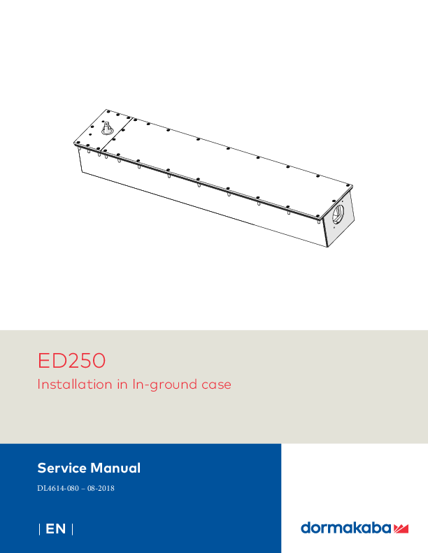
The ED250 operator is packaged in a cement case for in-ground floor installations. For double swing doors, two cement cases are supplied.
Fig. 2.1.1 In-ground case with ED250 operator
2.5 Maximum door weights
Door width
ED250
Inches
mm
Pounds
kg
28
711.2
700
340
32
812.8
700
340
36
914.4
700
340
39
990.6
700
340
42
1067
700
340
48
1219
700
340
2.2 ED250 low energy operator. CAUTION
ED250 in-ground is configured as a low energy operator from factory.
2.3 Arm configurations Fig. 2.3.1 Center hung
Fig. 2.3.2 Offset pivot
Fig. 2.3.3 Arm and track assembly (track in door)
1
2
TIPS AND RECOMMENDATIONS
Insure operator is qualified for use at the respective smoke or fire-rated door.
2.4 Cement case enclosure The cement case enclosure is listed and labeled to: � UL50, NEMA 4 water resistant enclosure � CSA 22.2 2.5 Floor threshold 1. Threshold to cover cement case and blockout is not
supplied with the ED250 in-ground package. Threshold installation and maintenance is customer responsibility. Refer to Chapter 8 for threshold maintenance. Fig. 2.3.4 Floor threshold
Threshold Cement case cover
1 Track 2 Slide
4 3
3 Arm 4 M8 shoulder screw
Blockout
4
ED250
DL4614-080
08-2018
dormakaba ED250 IG Service Manual
Chapter 3
3 Safety information
3.1 Safety instructions This document contains important instructions for installation of the ED250 in ground system. Review these instructions thoroughly prior to installation, and follow them carefully during installation, commissioning, troubleshooting and maintenance.
3.2 Door signage requirements Proper signs and labels shall be applied and maintained on the door controlled by the ED250 in-ground automatic swing door operator as referenced in: � ANSI/BHMA A156.19: Standard for power assist and
low energy power operated doors. Ref. Chapter 16. � Reference Chapter 7, Door signage.
3.3 Safety warnings
WARNING
Damage to equipment or incorrect equipment operation may result from an incorrect installation.
WARNING
Hand pinch point and crushing hazards at door closing edges!
WARNING Crushing hazards at door closing edges!
Fig. 3.1 Door closing edges
Secondary closing edge
Opposing closing edge
Main closing edge
WARNING
Hazard to mechanical processes by use of control settings, elements, or procedures not documented in this manual!
WARNING Electric shock hazard! By use of control elements, settings, or procedures not documented in this manual!
3.4 Residual hazards
WARNING
After installation, hazards such as minor crushing, impact with limited force, and risk to unsupervised children may exist depending on structural design of door area, type of door, and any safeguards that have been implemented.
WARNING
Work on electrical equipment and 115 Vac wiring installation must be performed only by qualified personnel!
WARNING
Metallic doors must be grounded per national and local codes!
ED250
DL4614-080
08-2018
5
dormakaba ED250 IG Service Manual
Chapter 4
4 ED250 in-ground cement case assembly
4.1 ED250 in-ground cement case overall assembly
1 Cement case 2 Cover 3 Gasket
Fig. 4.1.1 ED250 in-ground case dimensions
36"
7" 32
4 7/8" 1
(6 1/4" REF) 4 1/2"
� 2 3/8"
5.9"
Fig. 4.1.2 ED250 in-ground case cover and fasteners
1 In-ground case 2 Covers
24
(28) 3
2
3 8-32 x 3/4" PFHMS
6
(Phillips flat head
machine screw)
7
4 Center bearing
shaft, ED250-IG
5 Shaft seal
6 Gasket, 1/8" thick
1
7 2 3/8" hole for PVC
reducer coupling
25
4
2
(28) 3
6
ED250
DL4614-080
08-2018
dormakaba ED250 IG Service Manual
Chapter 4
4.2 ED250 in-ground cement case internal assembly
Fig. 4.2.1 ED250 in-ground case component view
1 ED250 in-ground
87
3
2 6 41 5
9
10
case
2 Gasket, 1/8" thick
3 8-32 x 3/4" FHMSPH
(flat head machine
screw, Phillips)
4 ED250 operator
5 PCB bracket
assembly 6 Operator drive axle
Fig. 4.2.2 ED250 operator
7 Center bearing
6
shaft
9
8 Shaft seal
9 Spring tension
adjustment
10 PVC reducer fitting
1 PCB bracket 1.1 PCB plate 1.2 PCB plate cover 2 Accessory
connection terminal board 3 Power off/on switch and 115 Vac connection board 3.1 115 Vac terminal block and connection board 4 Keypad and 2 digit display 5 Circuit board 6 Braking circuit plug receptacle 7 Power fail closing speed potentiometer 8 Program switch connector 9 Double door operator to operator communication cable port 10 Dorma Handheld communication port 11 Upgrade card slot 11.1 Upgrade card socket 12 1/4 x 1/2" x 1/2" SHCS 13 Ribbon cable
Fig. 4.2.3 ED250 PCB bracket assembly
1.2 1.1
(7)12 3 2
1
6 5
7
Fig. 4.2.4 Operator communication connectors, upgrade card slot
10
98
13
11 10 9
2
8
Fig. 4.2.5 115 Vac terminal block and wire harness assembly
3
3.1 115 VAC
Neutral
ED250
11.1
11
4
DL4614-080
08-2018
7
dormakaba ED250 IG Service Manual
Chapter 5
5 Recommended tools and torque chart
5.1 Recommended tools
Fig. 5.1.1 Recommended tools
1 T-handle hex key, 5 mm
2 Hex keys, 2.5 mm,
1
3 mm, 5 mm, 5/32"
3 Screwdriver, flat blade
2
4 Door pressure gauge,
0 to 35 ft - lbf
5 Screwdriver, Phillips,
4
#2, #3
6 Torque wrench,
3 to 50 ft lb min.
6.1 Metric hex key sockets
7 Open end wrench,
13 mm 8 Screwdriver, flat
6.1
6
blade, M2 (1/16 to
3/32")
3 5 7 8
5.2 5.3
Standard tightening torque
5.2.1 Standard tightening torque
Fastener size
ft lb
M5
3.7
M6
7
M8
17
M10
34
M12
58
Drill bits
5.3.1 Drill bit sizes for fasteners
Fastener
Drill bit size
#10 wood screw
Hardwood 9/64"
Softwood 1/8"
#12 wood screw
Hardwood 5/32"
Softwood 9/64"
#14 wood screw
Hardwood 11/64"
Softwood 5/32"
1/4 -20 metal self tapping screw
7/32"
10-24 barrel nut
5/32"
Fig. 5.3.1 Drill bit
8
ED250
DL4614-080
08-2018
dormakaba ED250 IG Service Manual
Chapter 6
6 User and terminal board interfaces
6.1 Overview, user interface
1 2 digit display 2 4 button keypad 3 PCB assembly
Fig. 6.1.1 ED250 in-ground cement case
Fig. 6.1.2 Operator keypad and display
6.1.1 Operator user interfaces 4 button keypad and 2 digit display: � 4 button keypad to select, input and
adjust door parameter values. � 2 digit display; parameter values, error
and information codes.
6.2 4 button keypad and display
2 2 digit display 6 Button legend
6.2.1 4 button keypad 4 button legend can be orientated so buttons have same function and position regardless of operator orientation. Button legend can be removed and rotated. 6.2.2 4 button keypad functions
Right button
1. Access parameter menu, press button > 3 seconds.
2. Edit selected parameter. 3. Save changed value.
Left button
1. Cancel parameter edit process.
2. Exit parameter menu, press button < 3 s.
Both buttons together
1. Acknowledge errors, press both buttons < 3 s.
2. Reset, press both buttons > 3 s.
Up button
1. Scroll through parameters and error messages.
2. Increase parameter value.
TIPS AND RECOMMENDATIONS
Keypad arrow symbols <, "less than" symbol >, "greater than" symbol
<3s: momentarily press button. >3s: Press button greater than
3 seconds.
3
1
2
Fig. 6.2.1 Keypad and display
6
< 3s Quit
> 3s Reset
> 3s
PRG
2
> 3s
< 3s
LEARN
> 8s
Fact-Setup
Down button
1. Scroll through parameters and error messages.
2. Reduce parameter value. 3. Opening pulse, press
button < 3 s. 4. Learning cycle, press
button > 3 s. 5. Reset with factory setting,
press button > 8 s (program switch CLOSE). 6. Identify operator orientation for display.
ED250
DL4614-080
08-2018
9
dormakaba ED250 IG Service Manual
Chapter 6
6.3 Program switch panel
1 Program switch panel
1.1 Program switch, 3 position
1.3 Exit Only switch, 2 position
1.2 Comm port for Dorma Handheld
2 RJ45 panel
Fig. 6.3.1 Program switch, RJ45 panels
1
2
1.1
1.2
1.3
1.2
6.4 Optional key switch panels
2 Key switch panel, RJ45, DX4604-21C
9 Key switch panel DX4604-11C
Fig. 6.4.1 Optional key switch panels
9 2
Wiring diagrams: Reference Appendix B
6.3.1 Program switch control modes. � Auto, door opens automatically when
one of the activators is actuated or triggered and closes on expiration of adjustable hold open time with no activators or actuators triggered. � Close, door closes automatically, or remains closed until program switch position changed. � Open, door opens automatically and remains open until program switch position changed. 6.3.2 Exit only switch modes. � Off, Interior and exterior activation sensors both active. � On, exterior activation sensor disabled when door fully closed. Only interior activation sensor will enable door opening. 6.3.3 RJ45 panel � Supplied on double door installations. � RJ45 cable connects panel to second ED250 in-ground operator for dormakaba handheld connection.
6.5 Operator status LEDs
5 Accessory terminal board
Fig. 6.5.1 ED250 in ground case assembly
1 Red LED 2 Yellow LED 3 Green LED 4 PCB assembly 5 Accessory terminal
board
5
Fig. 6.5.2 Operator status LEDs
3 2
1
4
5
6.5.1 Operator status LEDs In ground case cover must be opened to view LEDs. 1. Red LED
Blinking codes are used to indicate "ln__" information (system status or operating conditions) or certain error codes "E__". 2. Yellow LED Maintenance interval indicator. When illuminated, an indication the operator system has to be serviced. 3. Green LED � On, internal 24 Vdc power is On. � Off, internal 24 Vdc power is Off.
TIPS AND RECOMMENDATIONS
Details on LED status codes and maintenance intervals can be found in Chapter 18, troubleshooting chart.
10
ED250
DL4614-080
08-2018
dormakaba ED250 IG Service Manual
Chapter 6
6.6 ED250 terminal board accessory interfaces
Fig. 6.6.1 Terminal board electrical connections
1 Green LED (Para. 6.5) 2 Yellow LED (Para. 6.5) 3 Red LED (Para. 6.5) 4 Key (red insert)
DCW bus
Nightbank input
Activation inputs Interior Exterior
Safety sensors Swing side Approach side
0V + 24 V 8 - 24 AC/DC + 5% Wet + 24 V Signal input 0V + 24 V Signal input 0V + 24 V Signal input Test output 0V + 24 V Signal input Test output 0V
location in socket.
Assigned plug has tab
broken off in same
location.
5 Jumpers, factory
installed at following
terminals:
6
� 4 and 4a
� 15 and 3*
� 11 and 3*
3 B A 1 57 57a 1 42 3 1 41 3 1 15 17 3 1 11 13 3
* Remove jumpers if
X8
X10
X4
X5
safety sensors installed. 6 DCW� upgrade card plug included in scope
0 V Maximum current
5
24 V load: 1.5 A
1 5
of delivery.
7 Fire protection upgrade
7
card plug included in
scope of delivery.
COM Locking relay N.O. Maximum current:
1A, 48 V DC/AC N.C.
0 V
X3 Output
43 3 64 63 62 1G 3 24 VDC Class II
Locking feedback contact 2
97 98 99 30 31 32 34 33 3 35 3 1 3 6 1 4 4a
X6
X9 X1
X7 3
54
0V 0V + 24 V 0V Signal input 0V Partial Open Permanent Open Exit Only Automatic Off N.C. N.O. COM
(v1.7) Night-bank, 18K resistor not required
Emergency close
Smoke detectors
Night Program, exit only Door status
trigger
switches
ED250
DL4614-080
08-2018
11
dormakaba ED250 IG Service Manual
7 ED250 door signage
7.1 Low energy operator
7.1.1 Overview Signage and warnings are specified in ANSI /BHMA A156.19, American National Standard for power assist and low energy power operated doors.
7.1.2 All low energy doors Fig. 7.1.1 AUTOMATIC CAUTION DOOR decal
AUTOMATIC
CAUTION
DOOR
DD0586-010
DD0586-010
1. AUTOMATIC CAUTION DOOR decal. � All low energy doors shall be marked with signage
visible from both side of door with the words "AUTOMATIC CAUTION DOOR". � Signs shall be mounted 50" � 12" from floor to centerline of sign.
7.1.3 Knowing act switch used to initiate door operation1
Fig. 7.1.2 ACTIVATE SWITCH TO OPERATE decal
ACTIVATE SWITCH TO OPERATE
DD0758-010 DD0758-010
DD0758-010
1. ACTIVATE SWITCH TO OPERATE decal. � When a knowing act device is used to initiate operation
of door operator, door shall be provided with sign on each side of door where switch is operated with message "ACTIVATE SWITCH TO OPERATE".
7.1.4 Push/Pull used to initiate door operation. Fig. 7.1.3 PUSH TO OPERATE, PULL TO OPERATE decals
PUSH TO OPERATE
DD0762-010
DD0762-010
PULL TO OPERATE
DD0762-020
DD0762-020
1. PUSH TO OPERATE, PULL TO OPERATE decals. � When push/pull is used to initiate operation of door
operator, doors shall be provided with the message "PUSH TO OPERATE" on push side of door and "PULL TO OPERATE" on pull side of door.
12
ED250
DL4614-080
Chapter 7 08-2018
dormakabaED250 IG Service Manual
Chapter 7
7.2 Door signage, low energy swing doors, initiation of door operation
7.2.1 Single door Fig. 7.2.1 Activate Switch To Operate
Fig. 7.2.2 Push/Pull Push To Operate
Pull To Operate
AUTOMATIC
CAUTION
DOOR
DD0586-010
ACTIVATE SWITCH TO OPERATE
DD0758-010 DD0758-010
50" � 12"
AUTOMATIC
CAUTION
DOOR
DD0586-010
ACTIVATE SWITCH TO OPERATE
DD0758-010 DD0758-010
50" � 12"
AUTOMATIC
CAUTION
DOOR
DD0586-010
PUSH TO OPERATE
DD0762-010
50" � 12"
AUTOMATIC
CAUTION
DOOR
DD0586-010
PULL TO OPERATE
DD0762-020
50" � 12"
Pivot side
Pivot side
7.2.2 Double doors Fig. 7.2.1 Activate Switch to Operate
Pivot side
Pivot side
Fig. 7.2.2 Opposite side, no device
AUTOMATIC
CAUTION
DOOR
DD0586-010
ACTIVATE SWITCH TO OPERATE
DD0758-010 DD0758-010
50" � 12"
AUTOMATIC
CAUTION
DOOR
DD0586-010
ACTIVATE SWITCH TO OPERATE
DD0758-010 DD0758-010
AUTOMATIC
CAUTION
DOOR
DD0586-010
50" � 12"
AUTOMATIC
CAUTION
DOOR
DD0586-010
Fig. 12.623Push/Pull, Pull side
AUTOMATIC
CAUTION
DOOR
DD0586-010
PULL TO OPERATE
DD0762-020
50" � 12"
AUTOMATIC
CAUTION
DOOR
DD0586-010
PULL TO OPERATE
DD0762-020
Fig. 12.2.4 Push/Pull, Push side
AUTOMATIC
CAUTION
DOOR
DD0586-010
PUSH TO OPERATE
DD0762-010
50" � 12"
AUTOMATIC
CAUTION
DOOR
DD0586-010
PUSH TO OPERATE
DD0762-010
ED250
DL4614-080
08-2018
13
dormakaba ED250 IG Service Manual
7.3 Safety information label, low energy swing doors
7.3.1 Low energy swinging door safety information label
This AAADM label (Fig. 7.7.2) outlines safety checks that should be performed daily on singing door controlled by an ED250 configured for low energy operation.
7.3.2 Safety information label location Place label in a protected, visible location on door frame, near program switch panel if possible.
7.3.3 Annual compliance section of label This section of label is only completed on low energy swing doors that comply with ANSI/BHMA A156.19 standard and pass inspection by an AAADM certified dormakaba USA, Inc. technician.
7.3.4 Additional annual compliance inspection labels Place additional labels over annual compliance inspection section of safety information label. Fig. 7.3.1 Annual compliance label, low energy
ANNUAL COMPLIANCE INSPECTION
INSPECT FOR AND COMPLIES WITH ANSI
A156.19 ON: DATE: ______________
by AAADM Certified Inspector
Number: ___________
7.3.5 Safety information label Fig. 7.3.2 Low energy
SAFETY INFORMATION
Low Energy Swinging Doors
These minimum safety checks, in addition to those in the Owner's Manual, should be made each day and after any loss of electrical power.
1. Activate the door. Door should open at a slow smooth pace (4 or more seconds), and stop without impact.
2. Door must remain fully open for a minimum of 5 seconds before beginning to close.
3. Door should close at a slow, smooth pace (4 or more seconds), and stop without impact.
4. Inspect the floor area. It should be clean with no loose parts that might cause user to trip or fall. Keep traffic path clear.
5. Inspect door`s overall condition. The appropriate signage should be present and the hardware should be in good condition.
6. Have door inspected by an AAADM certified inspector at least annually.
DO NOT USE DOOR if it fails any of these safety checks of if it malfunctions in any way. Call a qualified automatic door service company to have door repaired or serviced.
See Owner's manual or instructions for details on each of these and other safety items. If you need a copy of the manual, contact the manufacturer.
AAADM-3044
AAADM
American Association of Automatic Door Manufacturers
ANNUAL COMPLIANCE INSPECTION
INSPECT FOR AND COMPLIES WITH ANSI
A156.19 ON: DATE:______________
by AAADM Certified Inspector
Number:___________
14
ED250
DL4614-080
Chapter 7 08-2018
dormakaba ED250 IG Service Manual
Chapter 8
8 ED250 in-ground door threshold
8.1 In-ground door threshold
Fig. 8.1.1 Threshold example for ED250 in-ground
NOTICE
Door threshold installation and maintenance is owner's responsibility
Fig. 8.1.2 Door threshold installation example for ED250 in-ground
8.1.1 Door threshold seal at spindle. CAUTION
Spindle opening at threshold must be sealed with an O-ring or similar device.
8.1.2 Door threshold perimeter seal CAUTION
Threshold perimeter must be sealed with a silicone sealant.
8.1.3 Cleaning door threshold and floor area around threshold.
CAUTION
Do not pressure wash door threshold or floor area adjacent to door threshold!
Fig. 8.1.3 Threshold installation end view example
Spindle Door threshold
ED250 in-ground cement case
WARNING
Access to the ED250 in-ground cement case must only be done by dormakaba USA Inc. certified technicians!
ED250
DL4614-080
08-2018
15
dormakaba ED250 IG Service Manual
Chapter 9
9 ED250 in-ground door maintenance
9.1 In-ground single swing door with offset pivot arm
1 ED250 in-ground cement case
2 Offset pivot arm 3 Door pivot (by
others) 4 Door frame pivot
(by others) 5 Door frame 6 Blockout � Threshold not
shown � Door transparent
for hardware views
Fig. 9.1.1 Left hand door with offset pivot arm
3
2
Fig. 9.1.2 Door overhead view
5 1
5
4
9.1.1 Offset pivot arm door maintenance. 1. Pivot arms, check for wear and tear.
1
23
9.2 ED250 in-ground single swing door with center hung arm
1 ED250 in-ground cement case
2 Blockout 5 Door frame 6 Center hung arm 9 Top of door and
door frame hardware (by others) Threshold not shown
Fig. 9.2.1 Door with center hung arm
Fig. 9.2.2 Door overhead view
5
1
6
6
1
6
9
2
1
9.2.1 Center hung door maintenance. 1. Center hung arms, check for wear and tear.
16
ED250
DL4614-080
08-2018
dormakaba ED250 IG Service Manual
Chapter 9
9.3 ED250 in-ground single swing door with arm and track
1 ED250 in-ground cement case
2 Blockout 3 Door 4 Butt hinge
(by others) 7 Track 8 Arm 9 Threshold
(by others)
Fig. 9.3.1 LH door with arm and track
4
Fig. 9.3.2 Overhead view, door closed
8
2
31
7
Fig. 9.3.3 Front view
7 8
8
7 9
Fig. 9.3.4 Arm and track
1 Track
2 Slide
1
2
3 Arm
4 M8 shoulder screw
4
3
2
1
9.3.1 Arm and track door maintenance. 1. Track, check for wear or damage. 2. Track, check for debris in track. 3. Slide, check for wear or damage.
9.4 Removing and reinstalling cement case cover
3 Cover 4 (21) 8-32 x 3/4" PFHMS
(Phillips flat head machine screws)
Fig. 9.4.1 ED250 cement case with cover installed.
3
4
ED250
9.4.1 Removing cement case cover. 1. Use a Phillips No. 2 screwdriver bit to
remove the twenty one 8-32 x 3/4" PFHMS securing the cover to the cement case.
9.4.2 Reinstalling cement case cover. 1. Insure gasket is clean and aligned with
case mounting holes, then place cover over gasket. 2. Using a Phillips No. 2 screwdriver bit, install the twenty one 8-32 x 3/4" PFHMS securing the cover to the cement case.
WARNING Access to the ED250 in-ground cement case must only be done by dormakaba USA Inc. certified technicians!
3. Hand tighten screws using a Phillips No. 2 screwdriver.
CAUTION
Do not over tighten cover screws!
DL4614-080
08-2018
17
dormakaba ED250 IG Service Manual
Chapters 10 and 11
10 Measure door width
10.1 Door width parameter Tb
10.1.1 Door width parameter. Door width is set in increments of 100 mm (4"), Measured width of 1000 mm (39.4") = Tb value of "10". ED250: [700- 1600 mm] 28" - 63"
10.1.2 Record door width
Parameter Tb value
10.2 Tb parameter values
10.2.1 ED250 door widths.
Door width measurement
Inches
[mm]
Tb
Width inches
36
[914]
to
to
9
36
39 15/16 [1014]
Door width measurement
Inches
[mm]
Tb
Width inches
44
[1118]
to
to
11 44
47 15/16 [1218]
40 to 43 15/16
[1016] to [1116]
10* 40
48
[1219]
to
to
12 48
51 15/16 [1319]
Door width measurement
11 Set reveal depth
11.1 Reveal depth parameter rd
11.2 rd parameter values
Parameter
2 rd
Description Reveal depth
Reference paragraph Para. 17.2
11.2.1 ED250 reveal depths, rd parameter.
Reveal measurement ED250
11.1.1 Reveal depth parameter. 1. Reveal depth is set in increments of 10 mm
(approximately 3/8").
11.1.2 Reveal depth parameter, center hung door. 1. Reveal depth: 0, rd = 0
11.1.3 Reveal depth parameter, offset pivot door. 1. Reveal depth: 3/4", rd = 2
Inches 0 3/8 3/4 1 1/8
[mm] rd
0*
0
10
1
20
2
30
3
11.1.4 Reveal depth parameter, arm and track. 1. Reveal depth: 1", rd = 3
18
ED250
DL4614-080
08-2018
dormakaba ED250 IG Service Manual
Chapter 12
12 Power fail closing speed
12.1 Set power fail closing speed
1 Power switch 2 Power fail closing
speed potentiometer 3 PCB bracket
assembly
Fig. 12.1.1 Power fail closing speed potentiometer
3
1
12.1.1 Power fail closing speed potentiometer.
� Single turn � Factory setting: fully CCW � CCW increases closing speed. � CW decreases closing speed. � 3/32" [2-3 mm] flat blade screwdriver
required for adjustment.
12.1.2 Setting door closing speed upon power failure.
1. Turn ED250 power switch OFF. 2. Manually open door to 90� angle and let
it close. 3. If door closes in less than 3 seconds, turn
potentiometer 1/4 turn CW and retry test.
2
TIPS AND RECOMMENDATIONS
Total door closing time from full open to fully closed should not be less than 5 seconds.
NOTICE
It is imperative that this door closing time be set. If door closes in less than three seconds, error message E 73 (System error 3, braking circuit) will be displayed. Reference Chapter 18, Troubleshooting.
ED250
DL4614-080
08-2018
19
dormakaba ED250 IG Service Manual
Chapter 13
13 Set braking circuit plug position
13.1.1 Set braking circuit plug position
1 Power switch 2 Braking circuit 3 pin
socket
Fig. 13.1.1 ED250 PCB bracket assembly
1 Braking circuit plug 2 Braking circuit
3 pin socket
1
Fig. 13.1.2 Plug position, pull
1 Braking circuit plug 2 Braking circuit
3 pin socket
1
2
Fig. 13.1.3 Plug position, push
2
1
NOTICE
Refer to Para. 17.2, configuration parameter AS (installation type) for door in-ground push and pull configurations.
2
13.1.1 Braking circuit plug Braking circuit plug is positioned in its 3 pin socket for either a door pull or push configuration. � Braking circuit plug is factory installed in
the left 2 pins, the pull position. (Fig. 13.1.2).
WARNING
Braking circuit will not work correctly if braking circuit plug is improperly positioned, or if an incorrect plug is used! Door may close at high speed and/ or be difficult to open!
13.1.2 Change braking circuit plug position. To change plug position for push door application, install plug in right 2 pins, toward user interface (Fig. 13.1.3).
WARNING
Insure power switch is OFF before changing plug position!
20
ED250
DL4614-080
08-2018
dormakaba ED250 IG Service Manual
14 Operator spring tension
14.1 Set operator spring tension
Fig. 14.1.1 Spring tension adjustment
1 Spring tension
1
adjustment
2 T handle hex key,
5 mm
Chapter 14 2
14.1.1 Spring tension setting revolutions
Door width
Inches
mm
Spring setting revolutions
36
42
48
914 1067 1219
ED250
14
14
18
TIPS AND RECOMMENDATIONS
System checks spring tension during learning cycle (Chapter 15). Learning cycle will be canceled if spring is insufficiently tensioned; door will stop and display will show a rotating "0" and an "F".
4 Door pressure gauge
Fig. 14.1.2 Door pressure gauge
4
14.1.2 Operator spring tension function 1. Spring tension sets closing force on door. 2. Required spring tension is based on door width. 14.1.3 Spring tension adjustment factory setting 1. Spring tension adjustment is factory set fully CCW,
no spring tension. 2. Spring has to be pretensioned per Para. 14.1.1.
Use 5 mm T handle hex key.
CAUTION
A minimum of ten spring tension revolutions are required to operate system.
CAUTION
Any change to spring tension setting requires a new learning cycle (Chapter 15)!
14.1.4 Check door closing force 1. Table 14.1.1 lists approximate spring tension settings. 2. Use pressure gauge to check door closing force at 2�
and adjust tension setting if necessary.
TIPS AND RECOMMENDATIONS
Reference Chapter 16, ANSI/BHMA standards for closing forces.
ED250
DL4614-080
08-2018
21
dormakaba ED250 IG Service Manual
Chapter 15
15 Learning cycle
CAUTION Learning cycle must be performed while motor is cold!
CAUTION Door must not be manually moved or held in position during the learning cycle!
Step 4
Step 5 Press
Display indicates door is at 70� position and is waiting for door opening angle to be set.
Manually move door to desired maximum opening angle (maximum door angle: 110�).
Momentarily press down button to continue learning cycle.
CAUTION
Verify that the following parameters have been set (Para. 17, Parameters):
� AS, Installation type � rd, Reveal depth � Tb, Door width � dL, Door type (double doors only)
TIPS AND RECOMMENDATIONS
During learning cycle: � Safety sensors and activators, are switched off to
insure learning cycle sequence is not interrupted. � Operator functions are deactivated.
Step 1
Secure motion range of door.
WARNING
No personnel or objects must be in range of door motion!
Step 2
Step 3 Press
Set program switch to CLOSE position.
Rotating "0" and an O indicate operator is ready for learning cycle.
Press and hold down button until display changes. � Door performs several movements
and display shows a sequence of symbols. � Movements of door must not be interrupted!
CAUTION Insure there are no obstacles to door movement!
Step 6
Step 7 Press Step 8 Step 9
� Door performs several movements and display shows a sequence of symbols.
� Movements of door must not be interrupted!
� Spring tension is too low if door stops and display shows a small rotating "o" and an "F".
If spring tension is too low:: � Turn off power and push or let door
close. � Increase spring tension (Chapter 14),
turn on power and restart learning cycle (Step 3).
Door will complete learning cycle. � Display with two horizontal bars
indicate operator is ready for operation.
Momentarily press down button to cycle door.
Following automatic learning cycle, actual forces on door, and door opening and closing times must be measured and changed if necessary to insure compliance with ANSI/ BHMA standards, reference Chapter 16.
Set program switch to Auto.
22
ED250
DL4614-080
08-2018
dormakaba ED250 IG Service Manual
Blank page
This page left intentionally blank.
ED250
DL4614-080
08-2018
23
dormakaba ED250 IG Service Manual
Chapter 16
16 ANSI/BHMA standards
16.1 A156.19 Low energy power operated doors
The following table references portions of content from ANSI/BHMA A156.19. Refer to the standard, available through ANSI or BHMA for additional information. Standard material reprinted with BHMA permission.
16.1.1 Door measurements, low energy power operated door
ED250 Parameter
A156.19 standard
Parameter
Function
Factory setting
Adjustment range Para. Requirement
So
Opening speed Swing door opening speed
250/s Note 1
ED250 8�/s - 27�/s Note 2
Opening Doors shall open from closed to back check or 80�, whichever occurs first, in 3 seconds or longer as required in Table I. 4.2 Total opening time to 90� shall be as in Table II (next page) If door opens at more than 90�, it shall continue at the same rate as backcheck speed.
Checking or slowing down of
bc
Backcheck
door speed before door being 10�
fully opened.
5� - 40�
4.2
Backcheck shall not occur before 60� opening.
Sc
Closing speed
Swing door closing speed, automatic mode.
25�/s Note 1
ED250 80/s - 27�/s Note 2
Closing
Doors shall close from 90� to 10� in 3 s or
4.4
longer as required in Table I (next page).
Doors shall close from 10� to fully closed in not less than 1.5 s.
dd
Hold open time
Hold open time
Time delay
When powered open, the door shall remain
5 s
5 s - 30 s
4.3
open at the fully opened position for not less than 5 s. Exception: when push-pull activation
is used, the door shall remain at the fully
opened position for not less than 3 s.
hS
Support for manual mode in door closed position.
Reference
hA
ED250 service manual for
Adjustment, door activation angle.
parameter
detail. hF
Power assist function.
Doors shall open: � With a manual force not to exceed 15 lb f to
release a latch if equipped with a latch.
4.5
� To set a door in motion 30 lb f .
� To fullyopen the door 15 lb f .
� Forces shall be measured 1" fro m latch edge of
door.
Fo
Static force in opening direction
Static force on door closing edge in opening direction.
13.5 lb f
Fc
Static force in closing direction
Static force on door closing edge in closing direction.
13.5 lb f
4.5 lb f - 15 lb f
4.5
4.5 lb f - 15 lb f
4.5
The force required to prevent a stopped door from opening or closing shall not exceed 15 lb f measured 1" from latch edge of the door at any point during opening or closing.
Note 1: Speed may be slower after learning cycle completed.
Note 2: Speed limited to 27� s in low energy mode.
24
ED250
DL4614-080
08-2018
dormakaba ED250 IG Service Manual
16.1.2 A156.19, Table I: Minimum opening and closing times.
"D" door width,
"W" door weight, pounds
inches
100
125
150
175
200
36
3.0 s
3.5 s
3.5 s
3.0 s
3.0 s
42
3.5 s
4.0 s
4.0 s
4.5 s
4.5 s
48
4.0 s
4.5 s
4.5 s
5.0 s
5.5 s
Minimum opening time to backcheck or 80 degrees (whichever occurs first). Minimum closing time from 90 degrees to latchcheck or 10 degrees (whichever occurs first).
16.1.3 A156.19, Table II: Total opening time to 90 degrees.
Backcheck at 60�
Backcheck at 70�
Backcheck at 80�
Table I plus 2 s
Table I plus 1.5 s
Table I plus 1 s
If door opens more than 90�, it shall continue at the same rate as backcheck speed.
Backcheck occurring at a point between positions shall use lowest setting.
16.1.4
Other door weights and widths Closing time T = (D W )/188 D = Width of door in inches. W = Weight of door in pounds. T = Closing time to latch check in seconds.
Chapter 16
ED250
DL4614-080
08-2018
25
dormakaba ED250 IG Service Manual
Chapter 17
17 Parameters
17.1 Parameters
17.1.1 Firmware version
TIPS AND RECOMMENDATIONS
� Parameters descriptions incorporate firmware versions v1.7 through v2.1.
� Version numbers are noted next to each applicable parameter description.
17.1.2 Firmware version and updates. � Operator firmware version is displayed during first
commissioning. Reference ED250 Installation Instructions Chapter 21. � Dorma Handheld can be used to check operator firmware version and to perform firmware updates. Reference Chapter 20, Dorma Handheld, or Dorma Handheld manual.
Fig. 17.1.1 Dorma Handheld terminal
17.1.5 Changing parameter values. 1. Set program switch to the CLOSE position
1 Program switch, 3 position
Fig. 17.1.2 Program switch
1
2. Use 4 button keypad as outlined in Steps 1 through 8 to view or change parameter values.
1 4 button keypad 2 2 digit display
Fig. 17.1.3 4 button keypad, 2 digit display
< 3s Quit > 3s Reset
> 3s PRG
2
> 3s
< 3s
LEARN > 8s
1
Fact-Setup
Step 1
17.1.3 Configuration parameters Configuration parameters (Para. 17.1.6) are set during first commissioning, reference ED250 Installation Instructions Chapter 21.
17.1.4 Driving parameters Driving parameters can be set once first commissioning has been completed. � Reference Para. 17.1.7 for a list of driving parameters. � Reference Para. 17.3 for details on each driving
parameter.
Step 2 Step 3 Step 4 Step 4
Step 5 Step 6 Step 7
Step 8
Press and hold right button greater than 3 s to enter program mode.
Press up or down button to scroll through parameters until desired parameter is displayed.
Press right button to display current parameter value.
Press right button again to enable editing of value, display will start flashing.
Press up or down button to select desired parameter value.
Press right button to save selected value. Display stops flashing.
Press left button to return to selected parameter.
Press up or down button to scroll through parameters until next desired parameter is displayed.
Press left button for a minimum of 3 s to exit program mode.
26
ED250
DL4614-080
08-2018
dormakaba ED250 IG Service Manual
17.1.6 Configuration parameters
Parameter
Description
1 AS
Installation type, Reference Para. 17.2.
2 rd
Reveal depth, Reference Chapter 11
3 Tb
Door width, Reference Chapter 10
4 dL
Door type, Reference Installation manual, Chapter 22.
17.1.7 Driving parameters Reference Para. 17.3 for parameter details.
Driving parameter
Description
5 So
Opening speed, automatic mode
6 Sc
Closing speed, automatic mode
7 dd
Hold open time, automatic mode
8 dn
Hold open time, night/bank
9 do
Hold open time, manual opening of door
10 Sb
Wall masking on door swing (hinge) side
11 ST
Safety sensor test
12 SA 13 SP
Activation by safety sensor on approach (opposite hinge) side
Suppression of safety sensor on swing hinge) side during initial movement (v1.9)
14 Ud
Locking mechanism delayed opening time
15 Pu
Door preload prior to unlocking
16 TS
PR (Power reserve) module test
17 Fo 18 Fc 19 EP
Static force on door closing edge in opening direction (wind load control)
Static force on door closing edge in closing direction (wind load control)
Motor driven latching action, automatic mode
20 EA
Door opening angle at which motor driven latching action is activated
21 FH
Keep closed force
22 PG
Push and Go
23 PS
Program switch type
24 S1 25 S2
DCW� EPS, electronic program switch behavior following a power reset
Internal program switch; switch function on delay
26 du
Door unlocking during business hours
27 Sr
Status relay function, terminal block X7
Chapter 17
Driving parameter
28 bE 29 CC 30 EC 31 CS 32 SL 33 OA 34 hd 35 hA 36 hF 37 hS 38 F1 39 F2 40 F3 41 F4 42 F5 43 F7 44 F8 45 C1 46 bc 47 Td
48 d1
49 d2 50 FC
51 Ad
52 HS 53 S3
54 S4
Description
Input 4/4a and X3, 1G 24V locking device output configuration
Cycle counter, number displayed * 10000
Delete error log
Reset service interval display (yellow LED)
Factory setting level (Fact Setup button)
Opening angle, set during learning cycle
Door closer mode, automatic or manual
Power assist function activation angle
Power assist function force adjustment
Power assist function support for manual mode in door closed position (v1.9)
Upgrade card, fire protection
This paragraph left intentionally blank.
Professional upgrade card, flip flop function, night/bank Professional upgrade card, extended hold open time Professional upgrade card, nurse-bed function (double doors only)
Upgrade card, barrier free toilet
Upgrade card, DCW� I/O module
Configuration of COM 1 interface
Back check angle when door opened manually
Door thickness [mm]
Deactivation of drive, emergency pushbutton at X4, 4 and 4a, trigger type (v1.7)
Night/bank function, trigger type (v1.7)
Hold open system release by manually closing door, trigger type (v1.7) Active door with astragal: caster angle, angle door must reach before passive door starts to open
Hinge clearance
OHC mode; permanent open via night-bank input (v2.1)
OHC mode; manual force overload drive release (v2.1).
ED250
DL4614-080
08-2018
27
dormakaba ED250 IG Service Manual
Chapter 17
17.2 AS installation type parameter
17.2.1 Set AS installation type parameter.
Step 1 Press
Press and hold right button greater than 3 sec. to enter parameter mode; AS parameter displayed.
Fig. 17.2.1 Arm and track, LH (push)
Interior
AS = 0
Step 2 Press
Step 3 Press
Displays "00" , factory setting. "00" starts flashing.
LH
Fig. 17.2.2 Arm and track, RH (pull)
Interior AS = 1
RH
Step 4 Press
Step 5 Press
Step 6 Press
Step 7 Press
Scroll to select parameter value. "1" shown as example.
Saves value entered. Display stops flashing.
Returns to Installation type parameter.
Exits parameter mode.
Fig. 17.2.3 Offset pivot arm, RH pull
AS = 4
RH
Fig. 17.2.4 Offset pivot arm, LH pull
AS = 3
Interior
Interior
17.2.2 AS parameter. Installation type, in-ground (IG)
Parameter value 0* 1 2
3
4
*
Parameter description
IG - Arm and track, LH push
IG - Arm and track, RH pull
IG - N/A
Overhead concealed (OHC) RH In-ground cement case: Offset pivot arm, LH pull Center hung arm, pivot at right jamb, LH pull/in Center hung arm, pivot at left jamb, LH push/out
OHC, LH In-ground cement case: Offset pivot arm, RH pull Center hung arm, pivot at right jamb, RH push/out Center hung arm, pivot at left jamb, RH pull/in
Factory setting
LH
Fig. 17.2.5 Center hung arm, pivot at right jamb RH push / out AS = 4
Interior
LH pull / in
AS = 3
Fig. 17.2.6 Center hung arm, pivot at left jamb AS = 3 LH push / out
AS = 4 RH pull / in
Interior
28
ED250
DL4614-080
08-2018
dormakaba ED250 IG Service Manual
Chapter 17
17.3 Driving parameters detail
17.3.1 Driving parameters detail.
Parameter
Value range
Units
Factory setting
Description
Opening speed, automatic mode
1. Opening speed refers to automatic mode, speed can be adjusted using this parameter.
2. Internal monitoring system checks if parameter setting is admissible. If setting exceeds
admissible value, the setting is alternately displayed with the permissible value.
5
ED250 8 - 60*
�/s
25
3. After parameter set, verify setting meets A156.19 (low energy) standards.
See Chapter 16.
* Maximum opening speed reduced to 27�/s in low energy mode.
Closing speed, automatic mode
ED250
6
2 - 60*
�/s
(v2.0)
1. Closing speed refers to automatic mode, speed can be adjusted using this parameter.
2. Internal monitoring system checks if parameter setting is admissible. If setting exceeds
admissible value, the setting is alternately displayed with the permissible value.
25
3. After parameter set, verify setting meets A156.19 (low energy) standards.
See Chapter 16.
*Maximum closing speed reduced to 27�/s in low energy mode.
Hold open time, automatic mode
0 - 30
s
7
5
0 - 180*
s
1. Hold open time starts once all internal, external, safety and push and go inputs have been opened or dropped, and door is in an open position.
2. Hold open time values from 0 to 30 are set in increments of 1 second. 3. Hold open time values greater than 30 seconds are set in increments of 5 seconds. 4. In low energy mode, a minimum hold open time of 5 seconds is required. 5. Hold open time can be re-triggered. *If hold open times greater than 30 seconds are desired, professional upgrade card extends maximum hold open time to 180 seconds.
Night-bank hold open time
8
0 - 30
s
1. Night-bank (key switch) hold open time is set using this parameter. 2. Night-bank Hold open time starts once contact on night-bank activator input is
opened and door is in an open position. 10
3. Night-bank hold open time can be re-triggered.
Hold open time, manual opening
1. Default hold open time of 1 second that follows every manual opening of door can be
adjusted using parameter do (v1.9).
9
0 - 30
s
1
2. Hold open time starts when door is released.
Wall masking on door hinge side
1. Wall masking required if door opens against an obstacle.
2. When door reaches set wall masking angle, system will ignore signal from safety
sensor on door swing (hinge) side.
3. The wider the detection range of safety sensor used, the greater the area must be in
which system has to ignore sensor's emitted signal. To insure personnel safety, it is
10
60 - 99
�
80
advised to keep this range as small as possible.
4. If set wall masking angle is exceeded when door is being opened, a rapidly flashing dot
appears in top left hand corner of 2 digit display.
5. Rapidly flashing dot disappears when door angle drops below set wall masking angle.
ED250
DL4614-080
08-2018
29
dormakaba ED250 IG Service Manual
Chapter 17
17.3.1 Driving parameters detail (Continued)
Parameter
Value range
Units
Factory setting
Description
Safety sensor test
Safety sensor parameter ST must be set to sensors used and if they are active-high or active-low. See E 04 safety sensor test error, Para. 18.4.
11
0 - 8
ST
0 Sensor test off. 1 Sensor test on swing (hinge) side. Active-high 2 Sensor test on swing and approach sides. Active-high 3 Sensor test on swing and approach sides. Active-high 0 4 Sensor test on swing side. Active-low
5 Sensor test on approach side. Active-low 6 Sensor test on swing and approach sides. Active-low
7 Wall mounted sensor with data line. Lock monitoring not available.
Activation by safety sensor on approach (opposite hinge) side
12
0 - 1
0
Suppression of safety sensor on swing (hinge) side during initialization drive
8
Sensor test, overhead sensor type Bodyguard III or Premier T with monitoring input. (v2.1)
0 Safety sensor's input is disregarded as soon as door is closed. 1 Safety sensor can trigger an opening pulse while door is closed.
0
Safety sensor on swing side is active during an initialization drive after a power on reset.
13
0 - 1
1. With SP set to 1, operator will disregard swing side safety sensor during
0
initialization drive (v1.9).
1
� After a power on reset, operator starts an initialization drive at slow speed. The
initialization drive cannot be completed if safety sensor on hinge side is, or has
been triggered.
Delayed opening time for locking mechanism
14
0 - 40 * 100
ms
3 *100
1. Delayed opening time delay starts as soon as door opening pulse has been generated. 2. Door opens on expiration of time delay. 3. If parameter is set to "0" and input for locking feedback contact is closed, door will not
perform a preload Pu before door unlocks. 4. Since various motor locks do not have feedback contacts, a delay of up to 4 seconds is
possible (v1.7).
Door preload prior to unlocking
15
0 - 9
1. Door preload prior to unlocking; force with which door is pushed in the "closed"
direction before door is opened.
2. The door may need to be pushed in closing direction (preload) in order to release
0
electric strike to insure door opens.
3. Preload time is set by parameter Ud, delayed opening time for locking mechanism.
4. To maintain long service life, set preload force only as high as necessary.
30
ED250
DL4614-080
08-2018
dormakaba ED250 IG Service Manual
Chapter 17
17.3.1 Driving parameters detail (Continued)
Parameter
Value range
Units
Factory setting
Description
Power reserve module SVP-PR 12 test
0 Test off
16
0 - 1
TS
1. SVP-PR 12 power reserve module test is performed once every 24 hours, or
10 minutes after AC power has been turned on. In event of an error:
� Unlocking is not performed and no automatic door movements are initiated.
� Error code E 25 is displayed, See Chapter 18, Para. 18.4, troubleshooting error
0
codes.
1
2. SVP-PR 12 power reserve module can be used but must be tested on a regular
basis if using:
� SVP-2000 DCW� emergency escape motor lock with automatic latching action.
� M-SVP 2000 DCW� emergency escape lock, v1.5 or later.
3. Test is automatically activated if a fire protection module is recognized in
conjunction with SVP-2000 DCW� or M-SVP 2000 DCW locks.
Static force in opening direction
2- 15 *10
N
17
.45- 3.4 *10
lbf
6 *10
1.35 *10
1. Static force in opening direction (basic parameter for wind load control). Static force on door closing edge can be changed using this parameter.
2. Internal monitoring system checks if parameter setting is admissible. If setting exceeds admissible value, the setting is alternately displayed with the permissible value.
3. After parameter set, verify setting meets ANSI/BHMA A156.19 standard. See Chapter 16.
4. Static force range is reduced with Low Energy mode. See Chapter 16.
Static force in closing direction
2- 15 *10
N
18
.45- 3.4 *10
lbf
6 *10
1.35 *10
1. Static force in closing direction (basic parameter for wind load control). Static force on door closing edge can be changed using this parameter.
2. Internal monitoring system checks if parameter setting is admissible. If setting exceeds admissible value, the setting is alternately displayed with the permissible value.
3. After parameter set, verify setting meets ANSI/BHMA A156.19 standard. See Chapter 16.
4. Static force range is reduced with Low Energy mode. See Chapter 16.
Motor driven latching action, automatic mode
19
0 - 9
0
Motor driven latching action angle (v1.7)
20
2 -10
�
3
Keep closed force
21
0 - 9
0
1. System offers a motor driven latching action in automatic mode in addition to mechanical latching action.
2. The EP parameter setting (v1.7) is designed to increase static force on door to insure proper closing despite resistance caused by door seals or locking devices.
3. Setting should be increased step by step from a low setting so as to avoid damage to the system. Use the lowest possible setting.
4. Ensure that both the door itself and the arm or track installation are suitable for the additional, permanent forces.
Door opening angle at which motor driven latching action EP is activated. � Starting angle of the latching angle adjustable from 10�. (v1.7).
0 Off
1. Keep closed force is:
1
� Permanently applied following motor drive latching action.
to
9
� Designed to keep door in closed position even if wind acts on door.
2. Keep closed force can be set from 0 (off) to 9, maximum force.
ED250
DL4614-080
08-2018
31
dormakaba ED250 IG Service Manual
Chapter 17
17.3.1 Driving parameters detail (Continued)
Parameter
Value range
Units
Factory setting
Description
Push & Go
0 Off
22
0 - 1
1. Parameter is activated.
2. Automatic opening of door is started when door is manually moved 4� out of the
0
1
closed position.
3. Door close mode parameter hd must be set to "0" (manual) to enable this
function.
Program switch type
23
0 - 4
0
DCW Electronic program switch (EPS) behavior following power reset
0 Internal, operator mounted program switches are active.
1
External mechanical program switch with contacts is connected to operator terminal board. Internal program switch connector must be removed.
2
External DCW� electronic program switch (EPS) is connected to operator terminal board. Internal program switch connector must be removed.
3 Program switch control by TMS Soft control software.
1. DCW� electronic program switch (EPS) is installed, and operator is also connected by the building management system to TMS Soft control software.
4 2. When PS is set to 4, the program switch functions can be changed from DCW� (EPS) to TMS Soft (v1.9).
24
0 - 1
0 0
1
Internal program switches, switch on delay 0
25
0 - 1
0 1
Unlocking during business hours 0
26
0 - 1
0 1
1. In event of power failure, or if operator is deliberately switched off, EPS will automatically switch to last known position when power returns.
2. Important: The time at which power returns might not be during business hours and may affect insurance-compliant door locking requirements.
1. In event of power failure, or if operator is deliberately switched off, EPS will automatically switched to OFF position when power returns.
2. This function should be used if insurance compliant locking if required.
Operator will perform function of new switch setting as soon as internal program switch is moved.
1. Operator will perform function of new switch setting after a delay of ten seconds from when internal program switch is moved.
2. This function is useful if user has to pass through door and its connected detectors and sensors after program switch is set to new function.
Door is always locked when it reaches closed position.
1. In automatic mode, door will not lock when it reaches closed position. This achieves faster door opening when system is equipped with motor driven locks.
2. If an electric strike opener is used, it must be suitable for 100% continuous duty factor to avoid possibility of damage.
32
ED250
DL4614-080
08-2018
dormakaba ED250 IG Service Manual
Chapter 17
17.3.1 Driving parameters detail (Continued)
Parameter
Value range
Units
Factory setting
Description
Status relay function, X7 terminals
0 Status relay is deactivated.
1 Status relay activated as soon as door reaches door "closed" position.
2 Status relay activated as soon as door reaches door "open" position.
3 Status relay activated when error codes are displayed on 2 digit operator display.
27
0 - 6
4 "Door closed and locked" activates status relay.
1
5
Status relay activated when information or error codes are displayed on 2 digit operator display (v1.9).
Locking device output configuration; output X3, 1G (24V) and input X6, 4/4a
28
0 - 1
0
1. Status relay activated when door is opened further than opening angle
6
parameter OA, set during learning cycle.
2. Parameter OA value can only be changed using Dorma Handheld or by
performing another learning cycle.
Reference Chapter 6
0 Locking device output terminal X3, 1G (24V) is independent of Input X6, 4/4a.
1. Locking device output terminal X3, 1G (24V) is turned on as soon as contact at
X6, 4/4a is opened (v1.9).
1
2. Terminal X3, 1G 24V output is on for as long as contact at X6, 4/4a is open,
motor lock with a 100% duty factor is required.
3. This function is not available for DCW� motor locks.
Cycle counter
29
0 - 99 * 10000
cycles
1. Total number of opening and closing cycles displayed is shown in increments of 10000. � Display value, "4", 40,000 cycles. � Display value, "53", 530,000 cycles. 2. Total number of cycles can be displayed on Dorma Handheld. 3. A display value of "99" means 990,000 cycles or greater.
Delete error log
30
0 - 1
0 No function.
0
1. When "1" entered, Error log is deleted.
1
2. Parameter is then automatically reset to "0".
Reset service interval display, operator yellow LED
31
0 - 1
0 No function.
1. When "1" entered:
� Service cycle counter is reset to 200,000.
� Service interval is reset to 12 months.
0
� Yellow LED not illuminated.
1
2. Parameter is then automatically reset to "0".
3. Values other than default values must be set using Dorma Handheld:
� Maintenance interval
� Maintenance cycles
ED250
DL4614-080
08-2018
33
dormakaba ED250 IG Service Manual
Chapter 17
17.3.1 Driving parameters detail (Continued)
Parameter
Value range
Units
Factory setting
Description
Factory setting level
Parameter SL is used to determine what data will be reset during factory setting process. Standard factory settings
� Program switches OFF.
� Door closed.
1
� Press 4 button keypad down button for > 8 s.
1. All parameters reset to factory settings.
2. Procedure completed when "8" on 2 digit displays blinks twice.
3. Installed upgrade cards remain valid and do not require reinstallation.
4. Learning cycle required.
32
1 - 2
1
Extended factory settings
� Program switches OFF.
� Door closed.
� Press 4 button keypad down button for > 8 s.
1. All parameters reset to factory settings.
2 2. Procedure completed when "8" on 2 digit displays blinks twice.
3. Installed upgrade cards deleted from operator memory.
4. Parameter SL automatically reset to 1.
5. Control unit and upgrade cards can be used independently (delivery status).
6. Learning cycle required..
Opening angle
33
0 - 110
�
Door closer mode
34
0 - 1
1
Power assist activation angle (v1.7)
35
1 - 5
�
3
1. Door opening angle set during learning cycle is displayed. 2. Opening angle can only be changed during learning cycle. 3. Due to installation and parameter tolerances, display value may not match actual door
position.
1. Automatic mode. This mode is applicable whenever door is mainly opened
automatically and where motion detectors are installed.
2. Mode is optimized for high frequency use.
3. Full energy upgrade card provides for higher door opening and closing speeds.
0
4. In case door is blocked during a closing cycle, operator reverses automatically.
5. Driving phase is optimized to provide reliable closing cycles.
6. Keep closed force (wind load control) parameter FH and Push & Go function
parameter PG are only available in automatic mode.
1. Manual mode. This mode is applicable whenever door is mainly used manually and only rarely automatically.
1 2. In case door is blocked during a closing cycle, door will stop at its current position. 3. Driving phase optimized for manual opening cycles. 4. Power assist function parameter hf is only available in manual mode.
1. Setting of door activation angle for Power assist function (hF). 2. Higher settings of hA result in better spring force compensation for easier manual
opening. 3. Power assist function is more sensitive the smaller the activation angle.
34
ED250
DL4614-080
08-2018
dormakaba ED250 IG Service Manual
Chapter 17
17.3.1 Driving parameters detail (Continued)
Parameter
Value range
Units
Factory setting
Description
Power assist function (v1.7)
36
0 - 10
1. Force setting for Power assist function.
2. Power assist function only available with hd parameter = 1, manual mode.
3. "0"; power assist function OFF; power assist function enabled for available values
greater than 0.
4. Power assist function enabled when power assist activation angle hA reached.
5. The greater the value of hF, the easier the door can be manually opened from power
0
assist activation angle hA.
6. If power assist set too high, door can open automatically.
7. Power assist function is not available
� If operator is switched off
� A smoke detector or emergency button has been triggered.
Power assist function support for manual mode in door closed position (v1.9)
37
0 - 10
0
hS
1. Setting for power assist function support with door in closed position. 2. Power assist function only available with hd parameter = 1, manual mode. 3. The greater the value of hS, the easier the door can be manually opened from the
closed position.
F1 , F3-F8 Upgrade card parameter values F2, ED100 full/low energy mode
0 - 3
0 Upgrade card not installed, function not available.
1 Upgrade card installed, function not activated. 0
2 Upgrade card installed, function activated.
3 Upgrade card has been removed, function no longer available.
Upgrade card, fire protection
38
0, 2, 3
1. Once upgrade card installed, parameter value will automatically change to 2.
2. Following activation, drive may be used as a electrically controlled hold-open system
according to EN 14637, Building hardware-Electrically controlled hold-open systems for
0
fire/smoke door assemblies, or similar standards.
3. Full energy function is automatically activated.
4. Plug for terminal board X9 socket included with upgrade card.
This paragraph left intentionally blank. 39
Upgrade card professional, impulse relay
40
0, 1, 2, 3
0
1. Once upgrade card installed, parameter value will automatically change to 1. 2. Function must be activated by changing parameter F3 to 2. 3. Door can be controlled with a pushbutton connected to Night-bank input without a
door hold open time: � Door opens with first pulse and remains open. The hold open time is not limited. � Door closes only with second pulse of pushbutton. 4. Pushbutton in 3. must be connected to terminal board Night-bank input: � X1, 3 and 35 (dry) � X10, 57 and 57a (wet) 5. Standard hold-open time dd is available when door is opened using other internal and
external detectors.
ED250
DL4614-080
08-2018
35
dormakaba ED250 IG Service Manual
Chapter 17
17.3.1 Driving parameters detail (Continued)
Parameter
Value range
Units
Factory setting
Description
Upgrade card professional, extended hold-open time
41
0, 2, 3
0
1. Once upgrade card installed, parameter value will automatically change to 2. 2. Setting range of dd, hold -open time is extended from 0 - 30 s to 0 - 180 s.
Upgrade card professional, nurse - bed function (double doors only)
42
0, 1, 2, 3
0
Upgrade card barrier free toilet
43
0, 1, 2, 3
0
1. Once upgrade card installed, parameter value will automatically change to 1. 2. Function must be activated by changing parameter F5 to 2. 3. For double doors, this function enables: � Separate door opening (only active door, nurse) � Both doors open (active, inactive doors, bed) � Permanent opening? 4. The activator connected to the external detector (terminal board X4, 41 and 3)
controls the active door (nurse function). Only the active door will open. 5. The activator connected to the internal detector (terminal board X4, 42 and 1) controls
the both active and inactive doors (bed function), both doors will open. 6. If Push & Go function PG is activated, only the active door will open in the event of a
manual opening. 7. Night-bank inputs will only cause the active door to open. 8. Exit only program switch function is not available with F5 activated.
1. Once upgrade card installed, parameter value will automatically change to 1. 2. Function must be activated by changing parameter F7 to 2. 3. Operator power reset is required; turn power switch off, wait 10 s and turn power back
on. 4. Upgrade card assigns inputs and outputs of the control unit with functions which are
required for this application.
Upgrade card DCW�
44
0, 2, 3
0
COM 1 configuration interface
45
0 - 1
0
Back check when door opened manually
46
5 - 40 (v1.9)
�
10
1. Once upgrade card installed, parameter value will automatically change to 2. 2. Upgrade card provides operator with DCW� bus connection. 3. Plug for terminal board X8 socket included with upgrade card. 4. DCW� bus enables connection of: � Program switch EPS DCW� (max. 2) � Motor lock controls SVP-S 2x DCW� (max. 2) � Motor lock SVP 2000 (max. 1) � RM-ED lintel mounted smoke detector � Key switch button ST 32 DCW� (max. 2) � I/O module DCW� (max. 1)
0 Interface programmed for communication with Dorma Handheld.
1 Interface programmed for use with Dorma TMS Soft control software.
1. Angle after which door is braked when manually opened. 2. Back check level is automatically optimized during manual door opening cycles. This
function improves door braking behavior in end position so door does not move beyond set opening angle OA (v1.7). 3. Entered value is subtracted from set opening angle OA. 4. Example � Opening angle, 90� � Parameter bc, 12� � Door back check starts at 78�.
36
ED250
DL4614-080
08-2018
dormakaba ED250 IG Service Manual
Chapter 17
17.3.1 Driving parameters detail (Continued)
Parameter
Value range
Units
Factory setting
Description
Door thickness
0 - 99 mm
35
1. Parameter is entered in mm.
2. Door thickness affects measured door opening angle.
47
Td
0 3 7/8"
3. Parameter Td enables a more accurate door width to be entered, if required. 1 3/8"
Deactivation of drive; X6, 4 and 4a, trigger type (v1.7)
48
0 - 1
0 NC contact, drive function is deactivated when NC contact is open.
0 1 NO contact, drive function is deactivated when NO contact is closed.
Night-bank contact X1; 3 and 35, trigger type (v1.7)
49
0 - 1
0
Release of hold-open system (v1.7)
1. NO contact, night-bank function is triggered when NO contact is closed. 0
2. Typically used when using a key switch or an access control system.
1. NC contact, night-bank function is triggered when NC contact is opened.
1
2. Typically used when connected to building management system to trigger doors
(signal normally present).
50
0 - 1
1. Upgrade care Fire Protection installed, users may release hold-open by manually
1
moving door in closed direction.
1
2. A manual release button is not required.
1. Hold-open release by manually moving door in closed direction is deactivated.
0
2. A manual release button is required.
Castor angle for double doors
51
0 - 30
�
Active door with astragal, angle active door must open before passive door opens. 30
Hinge clearance
� 5 *10
mm
52
�3/16 *10
inches
1. Clearance between hinges is critical for the calculated door angle.
3
2. It may only have a small effect but the clearance can be adjusted in extreme cases to
*10
improve accuracy.
3. Factory setting is 3 * 10, 30 mm, 1 3/16".
Overhead concealed (OHC) mode, permanent open via night-bank input (v2.1)
53
0 - 1
0
0 1
Overhead concealed (OHC) mode, manual force overload drive release (v2.1)
0
53
0 - 1
0 1
Function disabled. If night-bank is triggered > 5 s, operator changes to permanent open mode. The function is canceled by repeated impulse.
Function disabled. If door is manually moved against the direction of operator motor rotation, this is detected and the motor driving force is released to avoid damage to the operator mechanics.
ED250
DL4614-080
08-2018
37
dormakaba ED250 IG Service Manual
Chapter 18
18 Troubleshooting
18.1 Information and error codes
1 4 button keypad 2 2 digit display
Fig. 18.1.1 User interface
< 3s Quit > 3s Reset
> 3s PRG
2
> 3s
< 3s
LEARN > 8s
1
Fact-Setup
1 Red LED 2 Yellow LED 3 Green LED 4 PCB assembly 5 Accessory
terminal board
Fig. 18.1.2 Operator status LEDs
3 2
1
4
5
7 Program switch, Close position
Fig. 18.1.3 Program switch
7
CLOSE
AUTO
OPEN
TIPS AND RECOMMENDATIONS
Para. 18.2, LED status codes Para. 18.3, Information codes Para. 18.4, Error codes
NOTICE
Cement case cover must be removed to access user interface and status LEDs.
18.1.1 Overview Operator monitors internal circuits and external safety circuits managed by the operator.
18.1.2 Error and information messages 1. With operator in use, certain situations may develop
resulting in error or information messages. 2. Operator attempts to identify the cause and respond
accordingly. 3. Response depends on the severity of the error: � Information message (ln) � Error message (E) � Deactivating the operator's automatic function;
operator will switch to emergency mode. Users can then access door manually.
18.1.3 User information display. User interface display, or Dorma Handheld displays: � Information ln codes � Error message E codes
18.1.4 Viewing error messages. To access and view error messages, briefly press the right button on the 4 button keypad.
18.1.5 Red LED on operator . Red LED on terminal interface board displays blinking codes for: � Certain ln information � E status codes (Para. 18.2)
18.1.6 Resetting error codes. Options for resetting error codes: 1. Set program switch in Close (off) position. 2. User interface Reset buttons: � Press both left and right buttons >3s to reset
system (v1.8). 3. Power reset: � Turn power switch OFF. � Turn power switch back on after 10 seconds.
CAUTION
Always analyze and remove cause for error before resetting error message! E status code troubleshooting chart (Para. 18.3.4) is intended as a guide for diagnosing errors.
38
ED250
DL4614-080
08-2018
dormakaba ED250 IG Service Manual
18.1.6 Error message memory. 1. There are ten error message memory locations; E 0
through E 9. 2. The latest error message is always stored in error
memory location E 0: � As soon as another error occurs, the existing error
stored in E 0 will be moved to E 1 and the latest error will be stored in E 0. 3. A maximum of 9 errors can be stored in memory locations E1 through E9. 4. Identical error messages occurring one after another are not stored again.
18.2 Red LED status codes
18.2.1 Red LED status codes
Red LED status Steady flashing
Display Description
Control unit has detected error, emergency mode activated.
On steady Flashing 2 times Flashing 4 times
Flashing 5 times
ln 11 E 02 E 04
E 25
Hold-open device triggered.
Locking device error. Safety sensor test error.
SVP PR DCW� module test negative.
Flashing 5 times
Flashing 6 times
Flashing 6 times
Flashing 7 times Flashing 7 times Flashing 7 times Flashing 12 times Flashing 13 times Flashing 15 times
E 51
E 52
Incremental encoder error.
E 53
E 62
Double door operation, 2nd system has incompatible firmware version.
Double door operation, 2nd system
E 63
has incompatible fire protection
setting.
E 71
System error 1 (test), second shutdown option.
E 72
System error 2 (test), current measuring circuit.
E 73
System error 3 (test), braking circuit
E 12
EEPROM error
E 13
Motor overcurrent
E 15
Faulty learning cycle
ED250
DL4614-080
Chapter 18
08-2018
39
dormakaba ED250 IG Service Manual
Chapter 18
18.3 Troubleshooting chart, "ln" codes
18.3.1 Troubleshooting chart, information messages.
No.
Display
Red LED
Description
Troubleshooting information messages
ln 01
Obstruction Door obstructed by an Off obstacle or person; door movement stopped by operator.
Sustained operation on a door with an obstruction can result in damage to drive. 1. Object or person obstructing door movement. � Check door movement while system is deenergized. � Remove cause of anything obstructing door movement. 2. Sensor detection range too small. � Obstructions are often caused by people using door due to sensor's
detection range not matching operator's opening speed. Door is unavoidably contacted by person using door. � Sensors detection range should be increased and/or operator's opening speed should be increased. 3. Test system operation after cause of obstruction found.
Deactivation of drive function � Contact at X6, 4 and 4a is
An emergency close switch, lock switch, or other system safety device may be connected to the X6 input. 1. One of the activators connected to X6 may have opened, or a defect is
opened.
2
ln 08
Off
� Operator switched to
present. 2. Reset the applicable activator. Operator should start operation
emergency mode, door
automatically.
can only be used manually. 3. If ln 08 still present, check activators or system wiring.
Upgrade card error
1. Installed Upgrade card may not be removed from operator.
� Installed upgrade card has 2. If more than one upgrade card is installed, the first card installed becomes
been removed.
the container module.
� If two upgrade cards were � Reference chapter 19 for Upgrade card installation.
3
ln 09
Off
installed, the upgrade card � The container module must be installed last, after all other Upgrade cards
installed first (container
are installed.
module) has not been
3. If container module defective, first upgrade card (container module) must
reinstalled or is defective.
be replaced and all other upgrade cards must be reinstalled,
1. Hold-open system can be triggered:
� Automatically by smoke detector or building interface system.
� Manually by a manual release button.
� Manually moving door.
2. The system must be reactivated by a deliberate action.
3. Depending on system's configuration, reactivation can be done by:
4
ln 11
On
Hold-open system triggered.
� Manually moving door to taught opening angle.
� Switching program switch to Close (off).
� Pressing both 4 button keypad left and right buttons >3s.
4. It must be ensured that a smoke detector or building interface has not
been triggered.
5. If reactivation is unsuccessful, there may be a defect in the smoke
detector or building interface system or its connections.
Locking alarm
5
ln 23
Off � Door is blocked while in
the closed position.
1. Most common cause of this error is the drive unit attempting to open a locked door.
2. To eliminate the occurrence of this error, install a lock status switch. � Lock switch detects the lock pin's switching status and switches the drive
unit off if necessary. 3. It is recommended to use a lock status switch, as repeated attempts to
open a locked door may damage the drive unit or the door.
40
ED250
DL4614-080
08-2018
dormakaba ED250 IG Service Manual
Chapter 18
18.3.1 Troubleshooting chart, information messages.
No.
Display
Red LED
Description
Troubleshooting information messages
Communication error, double 1. Check communication cable connection at the two operators.
door system
� Cable connects to the horizontal RJ45 connector next to the user
6
ln 61
Off � No communication
interface (Chapter 4).
between the two operators.
2. Check communication cable.
Current measuring circuit � System could not
1. The initial current measuring test my not always be successfully
7
ln 72
Off
successfully perform
completed due to system tolerances and environmental conditions.
internal current measuring 2. The test may also fail, as an example, if someone uses the door while the
test , performed once
test is in progress.
every 24 hours.
Braking circuit test � System could not
successfully perform
8
ln 73
Off
internal braking circuit
test , performed once
every 24 hours.
1. The initial braking circuit test my not always be successfully completed due to system tolerances and environmental conditions.
2. The test also may fail, as an example, if someone uses the door manually while the test is in progress.
3. If the cyclical test fails ten times in a row, error message ln 73 will be displayed.
DCW� communication
1. Reconnect the corresponding DCW� device.
� At least one registered
2. If this is not possible, reactivate the drive. Reactivation can be done by:
9
ln 91
Off
DCW� device is missing. � Switching program switch to Close (off).
� Pressing both 4 button keypad left and right buttons >3s.
18.4 Troubleshooting chart, "E" codes
16.4.1 Troubleshooting chart, "E" codes.
No. Display Red LED � Description
Locking device error � Operator is attempting to open
1
E 02
Flashing 2 x
or close a locking device with feedback, or a DCW� locking device. An error has occurred
during this process.
Troubleshooting error codes
1. Probable causes are a defective locking device or wiring defect. � Check the locking device and feedback system.
2
E 03
Flashing 3 x
DCW� program switch is missing.
1. Check the DCW� program switch and its connections.
1. Factory setting level of "safety sensor test" parameter ST is 0,
test off (Chapter 17, Parameters).
Safety sensor test error
2. When ST is configured to installed safety sensors, a test signal is
� Test of moving safety sensors
sent to the sensors before each door opening or closing cycle.
3
E 04
Flashing 4 x
was unsuccessful.
Operator waits for a response within a certain time window.
3. Check whether parameter ST has been configured to the
installed safety sensors and their active-high or active-low signal
level.
4. Check for activation of the test at the safety sensors.
EEPROM error
� Internal memory check could
1. Using Dorma Handheld, reload current firmware to reinitialize
4
E 12
Flashing 12 x
not be completed. � Drive unit works in door closer
system. 2. If the error is still present, the control unit must be replaced.
mode.
ED250
DL4614-080
08-2018
41
dormakaba ED250 IG Service Manual
Chapter 18
18.4.1 Troubleshooting chart, "E" codes.
No. Display Red LED � Description
Overcurrent detection
� Motor is consuming more
5
E 13
Flashing 13 x
current than drive unit can
provide.
Faulty learning cycle.
6
E 15
Flashing � Learning cycle could not be 15 x
completed (Chapter 12).
Troubleshooting error codes
1. Motor is consuming too much power, check for any external causes.
2. Drive unit or control unit is defective. 3. If error repeats, operator must be replaced.
1. Error may occur if learning cycle has been interrupted, for example if door movement has been interrupted during the learning cycle.
2. Learning cycle must be repeated.
7
E 25
Flashing SVP-PR 12 power reserve module
5 x
test negative
1. See Chapter17, parameter TS, Power reserve module test. 2. Check power reserve module and its wiring.
Incremental encoder error
8
E 51 E 52 E 53
Flashing 5 x
� Motor gear unit encoder monitoring detected a faulty state.
1. Check encoder plug connection at operator: Ref. Chapter 4. � Secure connection. � Wiring terminations � Short circuits. 2. Check locking device for short circuits. 3. Error can be caused by defective motor or short circuit in locking
device. 4. Motor gear unit must be replaced in event of defective motor.
9
E 62
Flashing Incompatible firmware version,
6 x
double door system, second system.
1. Equip both operators with same firmware version.
10 E 63
Flashing Incompatible fire protection setting,
6 x
double door system.
1. For double door systems, the Upgrade card fire protection must be installed in both control units.
11 E 71
Flashing 7 x
System error 1, 2nd shutdown option
1. In order to reliably switch off the drive unit, several switching elements are used and their functions are tested periodically.
2. If the function test always results in the error code, the control unit must be replaced.
12 E 72
Flashing System error 2, current measurement
7 x
circuit
1. The current measurement circuit is part of the safety mechanisms and its function is tested periodically.
2. If the function test always results in the error code, the control unit must be replaced.
13 E 73
Flashing System error 2, current measurement
7 x
circuit
1. The braking circuit is a safety element in the closer mode and will be tested every 24 hours.
� During the test the motor is shut down during door closing and when the door closes at a set angle in emergency mode.
� Test can be noticed as a short jerk on the door and is normal. 2. Error can be due to door closing in the deenergized state too fast
(under 3 seconds). See Chapter 12. 3. Check the closing speed and reduce if necessary.
1. Movement dynamics in the closed direction will be reduced.
Energy management
� Motor is too hot (for example, too 2 Movement dynamics in both the open and closed directions will
14
high an ambient temperature)
be reduced.
� System responds automatically.
3 System shuts down for 3 minutes (door closer mode).
4 Hold-open time will be extended.
42
ED250
DL4614-080
08-2018
dormakaba ED250 IG Service Manual
Chapter 19
19 Upgrade cards
19.1 Upgrade cards
19.1.1 Upgrade card installation dormakaba USA Inc. upgrade cards can be used to expand the range of functions of the ED250 operator. When upgrade cards are installed, information is exchanged between and permanently allocated to both the operator control unit and the upgrade card.
Fig. 19.1.1 Upgrade card slot and socket
1 Upgrade card slot 2 Upgrade card
socket
Status LEDs 3 Green LED 4 Yellow LED 5 Red LED 6 Upgrade card
professional (green)
2
1
Fig. 19.1.2 Upgrade card status LEDs
3 4 5
6
19.1.2 Upgrade cards
Upgrade card
Fire protection
ED250
Professional
ED250
DCW�
ED250
Barrier free toilet
ED250
Upgrade card color Transparent red Green Yellow
19.2 Container module
19.2.1 Container module � The first upgrade card installed becomes
the container module. � Every operator control unit has only one
container module. � Functions of upgrade cards installed
after the first upgrade card are saved in the container module.
19.2.2 Container module removal � If the container module is removed, all
previously enabled functions will be deactivated after a certain time.
19.2.3 Operator control unit replacement � If the control unit is replaced, the
container module is removed from the old control unit and inserted into the new control unit. � The new control unit synchronizes with the container module and all upgrade card functions are available.
19.2.4 Inserting an upgrade card that has already been activated
� Rapidly flashing yellow LED on upgrade card indicates card is rejected.
� Card's functions in operator control unit are still valid.
19.2.5 Inserted a container module from third party control unit.
� Rapidly flashing yellow and green LEDs on container module indicates module is rejected.
� Container module can only be synchronized with one control unit.
19.2.6 Container module defective � Upgrade cards that were installed after
the container module must be reinstalled.
ED250
DL4614-080
08-2018
43
dormakaba ED250 IG Service Manual
Chapter 19
19.3 Installing upgrade cards
19.3.1 Set program switch to CLOSE.
1 Upgrade card slot
18
6 Professional
upgrade card
7 Container module
8 Program switch
9 2 digit display with
9
horizontal bar7
Set program switch to Close.
Horizontal bars indicate controller in stand by mode.
19.3.2 Installing first upgrade card
1 Upgrade card slot
2 First upgrade card
2
4 Yellow LED 7 Container module
1 4
7
1. Insert first upgrade card into upgrade card slot.
2. This card will become container module.
3. Yellow LED flashes on and off once during card insertion.
1 Upgrade card slot
3 Green LED
3
7 Container module
7
3 Green LED 7 Container module
4. Green LED slowly flashes on and off indicating communication between card and control module.
5. Upgrade card becomes container module, green LED continues to slowly flash on and off.
� Upgrade card function is now available.
TIPS AND RECOMMENDATIONS
Container module can be configured using applicable parameter (F1 - F8) for card. Reference Chapter 17.
19.3.3 Installing additional upgrade cards
7
1. Remove container
module from upgrade
1
card slot.
6 1 4
6
6 1
2. Insert next upgrade card into upgrade card slot.
� Card function is copied to control module; upgrade card is then invalidated.
� Yellow LED indicates procedure is complete.
3. Remove upgrade card from upgrade card slot.
7 1
3 7
4. Reinsert container module into upgrade card slot.
� Control unit recognizes container module; container module stores new functions.
� Green LED slowly flashes on and off indicating successful operation.
� New card functions are now available.
TIPS AND RECOMMENDATIONS
New upgrade card can be configured using applicable parameter (F1 - F8) for card. Reference Chapter 17.
44
ED250
DL4614-080
08-2018
dormakaba ED250 IG Service Manual
Chapter 20
20 dormakaba handheld
20.1 dormakaba handheld terminal
1 Off/On key 2 Function keys 3 Arrow keys 4 ENTER key 5 DEL key 6 SHIFT key 7 Alpha numeric
keyboard 8 LED, recharging
battery status (Off when batteries fully charged) 9 SD card slot
Fig. 20.1.1 dormakaba handheld
9 7
2
F1 F2 F3 3
4
6
SHIFT
ENTER
abc def
123
ghi
jkl mno
456
1
pqrs tuv wxyz
789
OFF .,# -+*/
8
ON 0 DEL
5
20.1.1 Interface cable Use dormakaba interface cable (Article No. 16596101170) to connect dormakaba handheld to operator Com 1 interface.
CAUTION
Never use conventional network cable with RJ45 plug! Using conventional cable may result in permanent damage to operator!
Fig. 20.1.2 Operator communication connectors, upgrade card slot
10
9
8
11.1
11
8 Program switch connector
9 Double door operator to operator communication cable port
10 Dorma Handheld communication port COM 1
11 Upgrade card slot 11.1 Upgrade card socket
20.1.2 Handheld key functions. 1. OFF ON, switches Handheld on or off. 2. Function keys F1 - F3, trigger functions shown in
bottom line of display (e.g., "RPT" for repeat, "UP" and "DOWN" to switch lines, "UpDoLd" for file up and download, "CHANGE" to change values, "OPEN" to trigger opening pulses. 3. Arrow keys, allow navigation within the display. Use left arrow to get back to previous screen. 4. ENTER, selects individual menu items and confirms changes of values and settings. 5. DEL, deletes figures or letters. 6. SHIFT, switch between figures and letters or small and capital letters. Current function is indicated on display (n: numeral, A: capital letters, a: small letters). 7. Alpha numeric keyboard, allows entering values and fie names in small and capital letters. There are several special characters (dot, comma, hash key, plus, minus, asterisk and diagonal slash). 20.1.3 Handheld startup. 1. Press OFF ON to turn on Handheld terminal. 2. Screen displays Current version, creation date and name of data base. Handheld is ready for operation. 3. Select "COMMUNICATION" and enter user code (DORMA original setting: 123456). 4. Handheld displays current software version of the connected operator (e.g., ED250 SW- V1.90). 20.1.4 Downloading current parameters. 1. Press function key F2 "UpDoLd" to access menu "UP/DOWNLOAD". 2. Select "Download" to download current adjustments and parameters. System stores this data as temporary file under file name "temp.tab". 3. Every change in configuration, parameter setting or special functions confirmed with the "ENTER" key automatically uploads to the operator. 4. The Handheld does not automatically save the changes. The Handheld will prompt you to save the changes when quitting the menu. 20.1.5 Menu structure
MAIN MENU Communication Files Change user code Extras
UP/DOWNLOAD Download Upload file Firmware upload Change user code
Door
CONNECTING...! User code: ****** Address: 1
MAIN MENU ED250 SW-V: 1.90 Again UpDoLd Door
temp.tab Configuration Driving parameters Special functions Diagnosis Save file as File upload
Door
ED250
DL4614-080
08-2018
45
dormakaba ED250 IG Service Manual
Chapter 20
NOTICE
Parameters and detail may change depending on firmware version.
20.2 dormakaba handheld; configuration parameters
"#" refers to reference numbers in Parameter list, Chapter 17. 20.2.1 Configuration parameters
#
Parameter and default
Description / Selections
#
Pull arm
14
1 Installation
* Push arm
Parameter and default
Lock delay
3
Gleit BGS (Track w push arm)
cm
Inches
15 Unlock force
0
2 Reveal depth 0 ED250 -3 ... 50
-1 3/16 ... 19 11/16
12
Test PR module
*
3
Door width (steps of 4")
100
ED250
70 ... 160
28 ... 63
single*
23
Program switch
*
4 Door type
1. leaf * 2. leaf
24
PGS power up (DCW)
*
Description / Selections
Delayed opening time for locking mechanism
(0 ... 3) *100 msec
Preload prior to unlocking
0 ... 9
0*
Test off
1*
Test once every 24 hrs.
Internal*
External
DCW
Last*
Off
Master
Slave
0
off
1
Pull side high active
25 PGS delay
26
Daytime unlock
Off* *
On
Off*
* On
Locking device remains permanently unlocked while door is in closed position.
2
Push side high active
11 Sensor test
0
3
Both sides high active
4
Pull side low active
5
Push side low active
6
Both sides low active
12
Start safety push side
*
7
Bodyguard
Off*
Signal ignored once door closed
On
Sensor can trigger pulse with door closed
Off
Relay off
Door status
27
(Status relay function, X7
terminals)
Open* Close * Error
Door reaches closed position Door reaches open position
Any error message
Door closed and locked
34
Manual mode
Power assist 35 winkel
(angle)
Information or error codes displayed
Door opened further than opening angle
On*
Manual mode on.
On
Off
Manual mode disabled.
3
Activation angle for power assist function (0 ... 5)
46
ED250
DL4614-080
08-2018
dormakaba ED250 IG Service Manual
20.2.1 Configuration parameters (continued)
#
Parameter and default
Description / Selections
36
Power assist kraft (force)
0
Force adjustment for power assist.
0 ... 10
21
Keep closed force
0
Force activated after latching action
0 ... 9
50
Manual release
Off; function deactivated. Manual release button required to deactivate hold open function.
On On; function activated. Moving door manually in closing direction from hold open position deactivates hold open function.
48
Input enable operator
Normal*
NC contact, operator deactivated when contact is open
*
Inverse
NO contact, operator deactivated when contact is closed
Chapter 20
#
Parameter and default
49
Input Night-bank
Description / Selections
Normal*
NO contact; nightbank function triggered while contact closed.
Inverse
NC contact; Nightbank function triggered while contact open.
47 Door depth
35
0 ... 99 mm
0 ... 7/8"
52
Hinge clearance
3
-5 ... +5 mm
-3/16 ... +3/16"
I04 Out 1
I04 Out 1
I04 Out 1
I04 Out 1
20.3 dormakaba handheld; driving parameters
20.3.1 Driving parameters
#
Parameter and default
Description / Selections
�/s
�/s
5 Speed open 25 ED250
8 ... 60
27 max. L.E. mode
6 Speed close
17
Limit force open
18
Limit force close
25 ED250
2 ... 60
27 max. L.E. mode
Static force in 60 opening direction
(wind load control)
(20 ... 150) N
60
Static force in closing direction (wind load control)
(20 ... 150) N
7
Hold-open time
5
Hold-open time automatic mode
(0 ... 180) s
#
Parameter and default
5
Offenhaltez man.
1
10
Wall blanking
80
19
Latching action
0
20
Latching angle
3
46
Back check angle
10
8
Nurse bed function
10
Hold-open time nurse bed function
(0 ... 180) s
51
Coord. offset angle
30
Description / Selections
Hold-open time manual mode
(0 ... 30 s
Angle when system ignores safety sensor on hinge side
(60 ... 99)�
Motor-driven latching action, automatic mode
(0 ... 9)
Opening angle, motor-driven latching angle activated.
(2 ... 10)�
Back check angle for manual opening cycles.
(5 ... 40)�
Starting angle for second door of two door system.
(0 ... 30)�
ED250
DL4614-080
08-2018
47
dormakaba ED250 IG Service Manual
Chapter 20
20.4 dormakaba handheld; special functions (Upgrade cards)
20.4.1 Special functions (upgrade cards)
#
Parameter and default
Description / Selection
Upgrade card status codes
� locked: not available � unlocked: available, not active � activ or active: activated � fehlt: upgrade card missing
#
Parameter and default
39
Full energy r/o
Description / Selection
locked
unlocked active
Upgrade card full energy (N/A)
locked
fehlt
40
Flip-flop func.
extend HOT (extended 41 hold-open time) r/o
unlocked active fehlt locked unlocked active fehlt
Upgrade card professional
Upgrade card professional
44
DCW r/o
Disabled 43 restr
r/o
locked unlocked active fehlt
Upgrade card DCW�
Upgrade card Barrier-free toilet
locked
42
Nurse-Bed func.
Fire 38 protection
r/o
unlocked active fehlt locked unlocked active
Upgrade card professional
Upgrade card fire protection
22 Push & Go
Off*
Door opens automatically
*
when moved manually by
On
4� from closed position. Only available when
"manual operation" is
turned "off".
fehlt
48
ED250
DL4614-080
08-2018
dormakaba ED250 IG Service Manual
Chapter 20
20.5 dormakaba handheld; diagnostics
20.5.1 Diagnostics
Parameter name Description
Setting
Parameter name Description
Setting
FW vers BM r/o
Rev FW version r/o
FW version SK r/o
Displays firmware (FW) x.x y y (e.g.,0190 version of basic module v 1.9.0)
0 ... zzz
Displays firmware version of Service Key
x x.y y (e.g., 01.00 = v 1.0.0)
FW bootloader
x x y y
Current error r/o Displays current error Error log 1
( ... ) ( ... )
Wartungs datum
Cycles total r/o
Zyklen max h r/o
Zyklen / h r/o
Maintenance data
x x y y (month, year)
Displays total opening and closing cycles
( .. )
Displays maximum number of cycles in one hour
( .. ) h
Displays number of cycles in previous hour
( .. ) h
Error log 2 Error log 3 Error log 4
( ... ) ( ... ) ( ... )
Zyklen / h akt. Learning cycle
Displays number of cycles in current hour
( .. ) h
Press "ENTER" to start learning cycle.
Cmd->
Error log 5 Error log 6 Error log 7 Error log 8 Error log 9 Current information
Delete errors
Displays current error
Press "ENTER" to delete error log.
( ... ) ( ... ) ( ... ) ( ... ) ( ... ) ( ... )
Cmd ->
Learn cycle stat. Indicates status of
r/o
learning cycle
( .. )
Factory reset
Latching action p/u
Press "ENTER" to reset system to original settings
Cmd ->
( ...) kg
Setup level (Ref. parameter SL, no. 28)
- Level 1, standard original settings. - Level 2, extended original settings
- Level 1 - Level 2
Installation dat r/o
Hours counter r/o
Displays date of
mmyy (e.g., 1110
installation (month / yr) November 2010)
Displays number of operating hours
( .. ) h
DCW� list r/o
DCW� reset
Displays DCW� list
List -> Cmd ->
Service time interval
Enter maintenance interval
(6 .. 24) months 12
Function mode r/o
Displays program switch setting
( .. )
Service cycle interval
Enter number of opening and closing cycles until next maintenance
(200 .. 1000)* 1000 200
ED250
DL4614-080
08-2018
49
dormakaba ED250 IG Service Manual
20.5.1 Diagnostics (continued)
Parameter name Description
Setting
Setting code
0, low active (function on) 1, function off
Inp. Night - bank Status of Night -bank
0
r/o
input X9, 6 and 1
1
Inp. OPEN r/o
Inp. PART OPEN r/o
Inp. EXIT ONLY r/o
Inp. AUTO r/o
Inp. OFF r/o
Status of program
0
switch permanent
OPEN input X1, 34
1
Status of program
0
switch PARTIAL OPEN
input X1, 33
1
Status of program
0
switch EXIT ONLY input
X1, 32
1
Status of program
0
switch AUTO input
X1, 31
1
0 Status of program switch OFF input X1, 30 1
Inp. Sfty pull side Status of safety sensor, 0
r/o
hinge side input X5, 15
1
Inp. Sfty push side r/o
Status of safety sensor, 0
opposite hinge side
X5, 11
1
Inp. Activ extern r/o
Status of external
0
activation sensor X6, 41 1
Inp. Activ intern r/o
0 Status of internal activation sensor X6, 42 1
Inp enable operator r/o
0 Status of Emergency close input X6, 4 and 4a 1
Inp. smoke
Status of smoke
0
detector
detector input
r/o
X9, 3 and 1
1
Inp. lock status r/o
Locking status
Status of locking device input X3, 43 and 3
0 1 locked
Chapter 20
Parameter name Description
Klemme 1G
Clamp X3, 1G and 3, 24 V out
Opening width r/o
Displays opening angle
Cur. door position Displays current door
r/o
angle
Amb. temp. r/o
Displays ambient temperature
Amb. max r/o
Displays maximum ambient temperature
Motor temp. r/o
Displays motor temperature
Motor temp max. Displays maximum
r/o
motor temperature
Com 1 r/o
Com 1 connection
Setting
( .. ) � ( .. ) � ( .. ) �C ( .. ) �C ( .. ) �C ( .. ) �C ( .. )
50
ED250
DL4614-080
08-2018
dormakaba ED250 IG Service Manual
Chapter 20
20.6 New dormakaba handheld; language change to English
Fig. 20.6.1 dormakaba handheld
20.6.1 New dormakaba handheld; language change.
If German language is displayed on screen when handheld is first turned on (Fig. 20.7.1, handheld power on sequence), use following steps to change to English.
Fig. 20.6.2 HAUPTMENUE (main menu)
5. Press ENTER to select Sprachen (Fig. 20.6.6). Fig. 20.6.7 Sprachauswahl (Language
Selection) menu
Sprachauswahl
Language: German
�nd
F1 F2 F3
SHIFT
ENTER
abc def
123
ghi
jkl mno
456
pqrs tuv wxyz
789
OFF .,# -+*/
ON 0 DEL
HAUPTMENUE
Kommunikation Dateien Benutzer code
F1 F2 F3
1. Scroll down Main Menu to EXTRAS: � Press 3 times to highlight EXTRA.
Fig. 20.6.3 Main Menu; EXTRAS highlighted.
HAUPTMENUE
Dateien Benutzer code Extras
6. Press F3 to select �nd (Amendments). Fig. 20.6.8 SPRACHEN menu
SPRACHEN
Deutsch Englisch
�nd
2. Press ENTER to select EXTRAS menu.
Fig. 20.6.4 EXTRAS menu
EXTRAS
Enstellungen Firmware-Liste
7. Scroll down SPRACHEN menu to Englisch: Press once to highlight "Englisch"
Fig. 20.6.9 Englisch highlighted
SPRACHEN
Deutsch Englisch
�nd
3. Press ENTER to select EINSTELLUNGEN (Settings) menu.
Fig. 20.6.5 EINSTELLUNGEN menu
EINSTELLUNGEN
Schnittstelle Kontrast Sprachem
Open
4. Scroll down EINSTELLUNGEN Menu to Sprachen (Languages):
� Press twice to highlight Sprachen.
Fig. 20.6.6 Sprachen highlighted
EINSTELLUNGEN
Schnittstelle Kontrast Sprachen
Open
8. Press ENTER to select Englisch. Fig. 20.6.10 SETTINGS menu
SETTINGS
Line interface Contrast Languages
Door
TIPS AND RECOMMENDATIONS
Handheld programmer will retain English setting when unit is turned off. Change to English only required the first time the programmer is turned on "out of the box".
ED250
DL4614-080
08-2018
51
dormakaba ED250 IG Service Manual
20.7 dormakaba handheld; firmware update
20.7.1 Firmware update procedure.
CAUTION For all firmware changes, set program switch to CLOSE and allow door to close completely before any updates are made!
Fig. 20.7.1 Handheld power on sequence
Chapter 20
1. Connect Handheld to COM 1 port (Para. 18.1) and power on.
� Handheld will boot up and display main menu.
1 ENTER button
Fig. 20.7.2 Select communication menu
Fig. 20.7.3 Enter Handheld user code
1
1
2. With Communication highlighted, press ENTER.
3. Enter Handheld user code and press ENTER.
52
ED250
DL4614-080
08-2018
dormakaba ED250 IG Service Manual
1 ENTER button 2 F2 button 3 Up/down arrows
Fig. 20.7.4 Select UpDoLd
Chapter 20
Fig. 20.7.5 Select Firmware upload
4. Press F2 to select UpDoLd. Fig. 20.7.6 Select Firmware version
5. Use Up and Down arrows to select Firmware upload and press ENTER.
Fig. 20.7.7 Start transmission
6. Use Up and Down arrows to select firmware version and press ENTER.
Fig. 20.7.8 Firmware uploading
7. Press any key to start firmware transmission.
Fig. 20.7.9 Complete firmware update
ED250
8. Firmware uploading to controller. Wait time of 3 to 5 minutes to upload.
DL4614-080
9. Press any key to complete firmware update.
08-2018
53
dormakaba ED250 IG Service Manual
Chapter 21
21 Cement case spindle and chain
21.1 Cement case chain tension
Fig. 21.1.1 Operator mounting screws
1 BHSCS (Flanged
button head socket cap screw)
44
1
2
2 Operator mounting
main extrusion
3 Spacer plate
4 1/4" x 5/8" FHCS
(flanged head cap
screw) and washer)
1
3
14
4
3 3/8" hex nut 4 Chain tension nut
(3/8" x 1 1/4" hex standoff) 5 3/8" x 2" long threaded stud
Fig. 21.1.2 Chain tensioning adjustment
4
3
53
1 3/8" thick pad 2 Plate for pad 3 3/8" hex nut 4 Chain tension nut
(3/8" x 1 1/4" hex standoff) 5 3/8" x 2" long threaded stud 6 Gearbox side
Fig. 21.1.3 Hex nuts loosened for chain tensioning
6
21
21.1.1 Check chain tension. Chain tension is set for a 3/8" deflection in chain when squeezed together. Chain tension adjustment is accomplished by adjusting chain tension nut (4) on a threaded stud. This moves ED250 operator toward or away from spindle drive, loosening or tightening chain.
21.1.2 Chain tension adjustment procedure.
1. Loosen four 1/4" x 5/8" FHCS (4) and three BHSCS (1) that secure operator to spacer plate (Fig. 21.1.1).
2. Loosen both 3/8" hex nuts (3) on threaded stud (Fig. 21.1.2).
3. Adjust chain tension nut (4) CCW to tighten chain or CW to loosen chain until 3/8" deflection in chain when squeezed together (Fig. 21.1.3).
4. Tighten both 3/8" nuts (3) against gearbox side (Fig. 21.1.4).
5. Retighten operator mounting screws loosened in step 1 to secure operator against spacer plate.
Fig. 21.1.4 Hex nuts tightened after adjustment
3
53
4
3
354
54
ED250
DL4614-080
08-2018
dormakaba ED250 IG Service Manual
Chapter 21
21.2 Cement case spindle height adjustment
4 5/16" x 2" cup point set screw
5 5/16" x 5 1/2" cap screw
6 Adjustable plate 8 Spindle
1 Gearbox cover access hole for set screw
2 Top gearbox plate access hole for set screw
5 5/16" x 5 1/2" cap screw
6 Adjustable plate 7 Cement case cover 8 Spindle 9 Top gearbox plate
Fig. 21.2.1 Height adjustment set screws
8 6 55
44
Fig. 21.2.2 Threaded post adjustment holes, 5/16" x 5 1/2" cap screws
1
8
25
1
5
9
21.2.1 Spindle height adjustment. Spindle bearing is mounted to adjustable plate (6). Two 5/16" x 5 1/2: cap screws (5) secure the adjustable plate and spindle height in position. Spindle height adjustment is accomplished by turning three 5/16" x 2" set screws (4) clockwise to raise the adjustable plate and counter clockwise to lower the adjustable plate.
21.2.2 Access holes for set screws. 1. Gearbox cover contains access holes (1)
for two set screws (Fig. 21.2.2). 2. Top gearbox plate (9) contains access
hole (2) for one set screw (Fig. 21.2.2).
21.2.3 Adjusting spindle height. 1. Remove two set screws (3) from gearbox
cover access holes (1) using 5/32" T-handle hex key (Fig. 21.2.3). 2. Slightly loosen two 5/16" x 5 1/2" cap screws (5) using 9/16" socket. 3. Rotate the three cup point set screws (4) (Fig. 21.2.1) clockwise to raise spindle height and counter clockwise to lower height. Use 5/32" T-handle hex key. � Turn each set screw an equal amount when adjusting spindle height.
1 Cover access hole; set screw
2 Top gearbox plate access hole; set screw
3 Access hole set screw
5 5/16" x 5 1/2" cap screw
6 Adjustable plate 7 Cement case cover 8 Spindle
Fig. 21.2.3 Set screw removal
3
78
2
5
1 3
1
21.2.4 Spindle height adjustment completed.
1. Tighten two 5/16" x 5 1/2" cap screws (5) using 9/16" socket (Fig. 21.2.3).
2. Reinstall two set screws (3) in cover access holes (Fig. 21.2.3).
6 5
ED250
DL4614-080
08-2018
55
dormakaba ED250 IG Service Manual
Chapter 21
21.3 Spindle centering
1 Spindle 1.1 Spindle gearbox 2 5/16" x 3/8" flange
head cap screw 3 Slide mounting
plate 4 1/4" x 3/4" cap
screw 5 Gearbox top 6 5/16" x 1" cap screw 7 Block, operator
mounting 8 Operator mounting
main extrusion 9 Angle iron with
threaded hole for (6) 10 Pad, operator
mounting 12 Cement case
Fig. 21.3.1 Spindle centering hardware 1.1
1
4
5 23
8
Fig. 21.3.2 Spindle centering hardware, cement case side view
4
2
3
8
11
67
32
9
9 6
2
3 7 10
CAUTION
Cement case adjustments include: � Spindle height (Para. 21.2) � Chain tension (Para. 21.1). Para. 21.3 is reference information for establishing spindle center at factory.
TIPS AND RECOMMENDATIONS
Cement case shown transparent for internal case views.
21.3.1 Spindle centering in cement case. Spindle gearbox (Fig. 21.3.1, item 1.1) is secured to operator mounting main extrusion (Fig. 21.3.1 item 8). Main extrusion location is set at factory against cement case sidewalls using adjustments in Para. 21.3.2 and .3.
56
ED250
DL4614-080
08-2018
dormakaba ED250 IG Service Manual
1 Spindle 2 5/16" x 3/8" flange
head cap screw 3 Slide mounting
plate 4 1/4" x 3/4" cap
screw 8 Main extrusion,
operator mounting 12 Cement case
Fig. 21.3.3 Spindle side adjustment
1
4 12 3 3 8
6 5/16" x 1" cap screw 7 Block, operator
mounting 8 Operator mounting
main extrusion 9 Angle iron with
threaded hole for (6) 10 Pad, operator
mounting 12 Cement case
Fig. 21.3.4 Spindle lateral adjustment
8
Chapter 21
21.3.2 Operator mounting main extrusion side position against cement case.
1. Two side mounting plates (Fig. 21.3.3, item 3) are used as spacers holding extrusion against opposite cement case wall.
21.3.3 Main extrusion side position adjustment.
1. 1/4" x 3/4" cap screw (Fig. 21.3.3, item 4) is used to move extrusion against opposite cement case wall (factory adjustment).
21.3.4 Main extrusion lateral position. 1. 5/16" x 1" cap screw and operator
mounting block and pad (Fig. 21.3.4, item 6,7 and 10). 2. Cap screw is adjusted against block and pad to hold position of main extrusion against end of cement case (factory adjustment).
6 9 7 10
57
ED250
DL4614-080
08-2018