Centurion G-SPEAK Ultra GSM Intercom User Guide
File info: application/pdf · 2 pages · 1.01MB
G-SPEAK ULTRA Quick Guide SA-Only(1034KB)
CENTURION Gate Motor Manuals and Product ation
G-Speak Ultra Quick Guide
Centurion G-Speak Ultra GSM 4G Kit – Sawyer Security
Full PDF Document

If the inline viewer fails, it will open the original document in compatibility mode automatically. You can also open the file directly.
Extracted Text
www.centsys.com
Connect with us on: facebook.com/centurionsystems YouTube.com/centurionsystems
@askcenturion centurion.systems
Subscribe to the newsletter: www.centsys.com/subscribe
Call Centurion Systems (Pty) Ltd . South Africa Head Office: +27 11 699 2400
Call Technical Support: +27 11 699 2481 from 07h00 to 18h00 (UTC+2)
www.centsys.com.au
Call: 1300 CENTSYS (1300 236 879) After Hours International Technical Support Call Centre +27 11 699 2481 (16:00 to 02:00 - Australian Eastern Time)
E&OE Centurion Systems (Pty) Ltd reserves the right to change any product without prior notice
All product and brand names in this document that are accompanied by the � symbol are registered trademarks in South Africa and/or other countries, in favour of Centurion
Systems (Pty) Ltd, South Africa. The CENTURION and CENTSYS logos, all product and brand names in this document that
are accompanied by the TM symbol are trademarks of Centurion Systems (Pty) Ltd, in South Africa and other territories; all rights are reserved. We invite you to contact us for further details.
ISO 9001:2015
Doc number: 1265.D.01.0014_1 SAP Code: DOC1265D0114
GSM-BASED INTERCOM SYSTEM
G-SPEAK ULTRA QUICK GUIDE
Centurion Systems (Pty) Ltd www.CentSys.com
1. Important Safety Instructions
1. Do not install this product near the DOSS sensor inside the gate motor housing or near the remote receiver.
2. Do not install this product near any sensitive electrical components. 3. All installation, repair, and service work to this product must be done by a
suitably-qualified person. 4. Do not in any way modify the components of the system. 5. Do not install the equipment in an explosive atmosphere: the presence of
flammable gas or fumes is a serious danger to safety. 6. Do not leave packing materials (plastic, polystyrene, etc.) within reach of
children as such materials are potential sources of danger. 7. Dispose of all waste products like packing materials, according to local
regulations. 8. Centurion Systems (Pty) Ltd does not accept any liability caused by
improper use of the product, or for use other than that for which the GSM system was intended. 9. This product was designed and built strictly for the use indicated in this documentation. Any other use, not expressly indicated here, could compromise the service life/operation of the product and/or be a source of danger. 10. Anything not expressly specified in these instructions is not permitted.
This icon denotes variations and other aspects that should be considered during installation.
This icon indicates tips and other information that could be useful during the installation.
2. Technical Specifications
Supply Voltage Range Maximum Current Draw Input/output Current Rating Input Sense Voltage Range
Network Provider
Number of Configurable Input/ output Channels Call Buttons on Calling Module Call confirmation at Calling Module Model Options
11-24V DC 300mA @ 12V DC 50mA (Open Collector) 0-24V DC (0-1.6V Low-input State, 5V-24V High-input State) MTN - South Africa Only
4
2
Yes
GSM 2G: 850/900/1800/1900MHz (EDGE) GSM 3G: 900/2100MHz (EDGE) 900/2100MHz (UMTS) GSM 3G PENTA: 800/850/900/1900/2100MHz (UMTS) GSM 4G/LTE-CAT1: 900/2100MHz
TABLE 1
3. Product Identification 3.1. G-SPEAK ULTRA
1 7
4. Device Layout and Wire Connections
Optional: External Antenna
NOTE: The Internal Antenna is selected by default.
SIM Card
nanoSIM
Scroll Left
Scroll Right
Enter / Home
5. LCD Interface
Table 2 below lists the information shown on the different screens found on the LCD interface. The left and right scroll buttons are used to toggle between the different screens.
Home Screen Network Name or Phone Number Applicable to Incoming / Outgoing SMS or Call.
Network Signal Strength
Connected to Internet
Connected to G-WEB
Device has Error Condition
Incoming SMS
Outgoing SMS
Incoming Phone Call Events
Outgoing Phone Call Events
IO Status Screen Input: Deactivated ("E" = Input event reached) Input: Activated (pulled to ground) ("E" = Input event reached)
Output: Off
Output: On (pulling to ground)
Voltage/Firmware/Date & Time Screen
� Supply Voltage
� Time
� Firmware Version � Date
Phone Number Screen Device SIM Phone Number.
Airtime Balance Screen
6
Outgoing Call Credits
2
Outgoing SMS Credits
3
4
1. Fascia 2. External Antenna Cover 3. Main Unit 4. Mounting Plate
5
5. Terminal Blocks 6. Navigation panel 7. LCD Screen
FIGURE 1
GSM Antenna Selected Screen Internal GSM Antenna Selected (default).
External GSM Antenna Selected (connect own Antenna to SMA connector). Press Enter to change between Internal and External Antennas.
Gate Status Screen
Gate Closed
Gate Opening
Gate Open
Gate Status Warning
G-SPEAK ULTRA
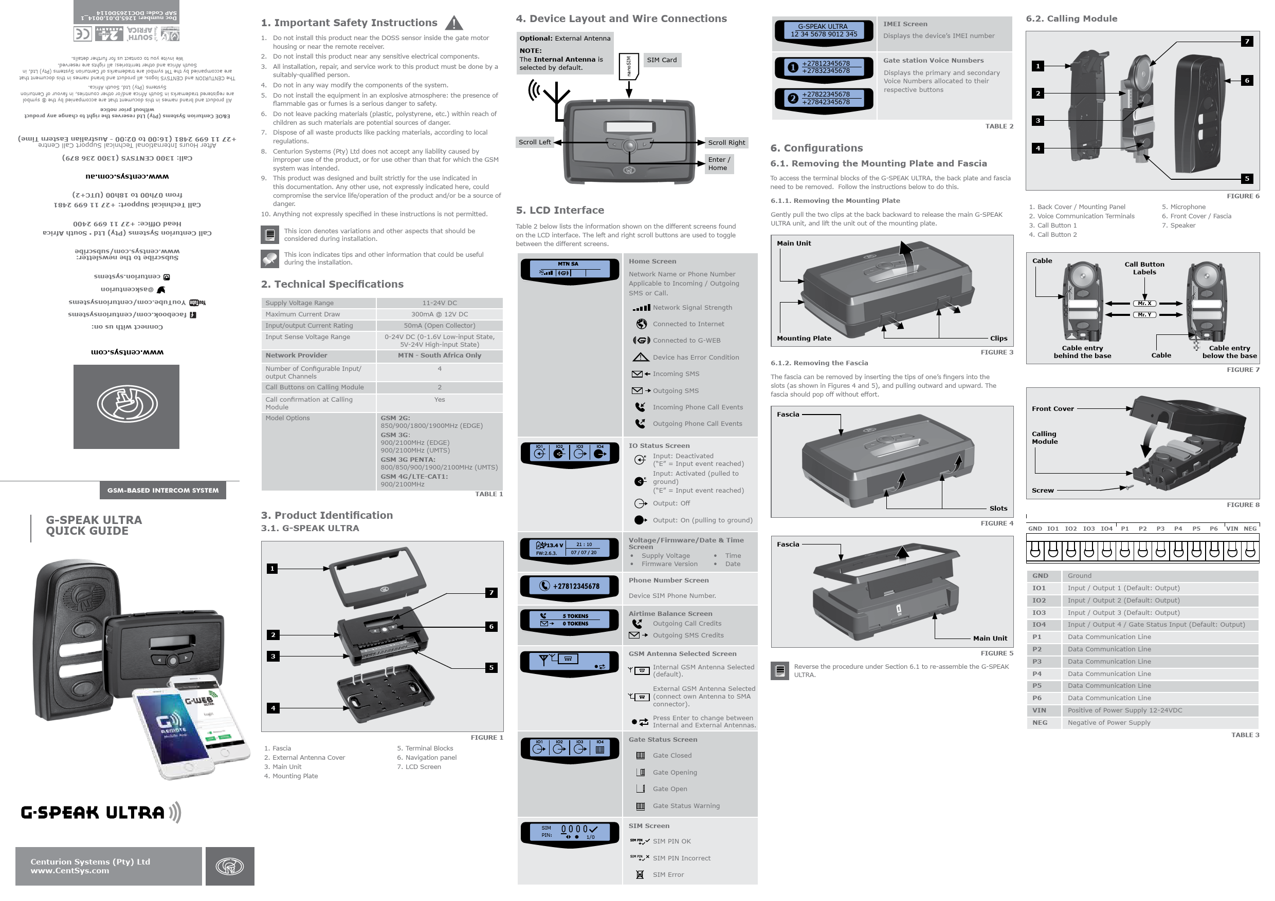
IMEI Screen
6.2. Calling Module
12 34 5678 9012 345
Displays the device's IMEI number
7
1
+27812345678 +27832345678
Gate station Voice Numbers Displays the primary and secondary
1
Voice Numbers allocated to their
6
2
+27822345678 +27842345678
respective buttons
2
3 TABLE 2
6. Configurations 6.1. Removing the Mounting Plate and Fascia
To access the terminal blocks of the G-SPEAK ULTRA, the back plate and fascia need to be removed. Follow the instructions below to do this. 6.1.1. Removing the Mounting Plate Gently pull the two clips at the back backward to release the main G-SPEAK ULTRA unit, and lift the unit out of the mounting plate.
Main Unit
4
1. Back Cover / Mounting Panel 2. Voice Communication Terminals 3. Call Button 1 4. Call Button 2
5
FIGURE 6 5. Microphone 6. Front Cover / Fascia 7. Speaker
Cable
Call Button Labels
Mounting Plate
Clips
6.1.2. Removing the Fascia
FIGURE 3
The fascia can be removed by inserting the tips of one's fingers into the slots (as shown in Figures 4 and 5), and pulling outward and upward. The fascia should pop off without effort.
Fascia
Cable entry behind the base
Front Cover Calling Module
Mr. X Mr. Y
Cable
Cable entry below the base
FIGURE 7
Fascia
Slots FIGURE 4
Screw
FIGURE 8
GND IO1 IO2 IO3 IO4 P1 P2 P3 P4 P5 P6 VIN NEG
Main Unit
FIGURE 5 Reverse the procedure under Section 6.1 to re-assemble the G-SPEAK ULTRA.
GND IO1 IO2 IO3 IO4 P1 P2 P3 P4 P5 P6 VIN NEG
Ground Input / Output 1 (Default: Output) Input / Output 2 (Default: Output) Input / Output 3 (Default: Output) Input / Output 4 / Gate Status Input (Default: Output) Data Communication Line Data Communication Line Data Communication Line Data Communication Line Data Communication Line Data Communication Line Positive of Power Supply 12-24VDC Negative of Power Supply
TABLE 3
SIM
SIM Screen
PIN:
1/0
SIM PIN OK
SIM PIN Incorrect
SIM Error
6.3. Wiring Diagrams (Please refer to the online G-ULTRA wiring diagram document for more diagrams)
Do not mount close to DOSS sensor or remote receiver.
To prevent noise on call audio: 1) Power supply / charger must be earthed from AC mains cable. 2) Screened cable is recommend and screen must be connected to G-SPEAK GND only.
G-SPEAK ULTRA
Calling Module
P1 P2 P3 P4 P5 P6
GND IO1 IO2 IO3 IO4 P1 P2 P3 P4 P5 P6 VIN NEG
6.4.3. G-REMOTE Mobile App (Users)
Download the G-REMOTE mobile app now for free by scanning the QR code on your mobile device. G-REMOTE lets you remotely control your GSM devices from your phone and receive push notifications for systems that are being monitored.
Get it on
Download on the
App Store
D-Series Controller
Looking for more wiring diagrams and product applications? Scan the QR code on your mobile device to be taken to our wiring diagram library.
FIGURE 9
6.4. Configuration of features
All features � both basic and advanced � can be easily, and remotely, configured via our G-WEB Mobile Phone App or our G-WEB Online Interface. By simply logging on to the G-WEB App or G-WEB, you can add and delete users, specify text for input notifications and activations, modify device characteristics and many other features. Download the G-WEB mobile App from your Smart Phone by navigating to the App store or go to http://www.gweb.co.za
It would be necessary to register if you have not previously done so.
There is no need to download a third party QR Scanner, as there is a QR Scanner that is built into the G-WEB ULTRA Mobile App.
6.4.1. G-WEB Mobile App (Installers)
To download the G-WEB Mobile installer app, simply scan the QR code on your mobile device to be taken to the app in the applicable app store for your operating system. The G-WEB app gives you on-the-go access to a multitude of configuration and admin settings.
6.4.2. G-WEB Online
Your CENTURION GSM devices can be remotely managed and configured using the G-WEB online interface. Scan the QR code to be taken to G-WEB online.
Get it on
Download on the
App Store