GS34P02Q14-01E
File info: application/pdf · 27 pages · 1.30MB
GS34P02Q14-01E
15th Edition: Feb. 22, 2021
FCN-500 - General Specifications
22, 2021(YK) ... *10: When FCN is used under the ATEX Type "n" environment, the Instruction Manual, "Explosion Protection of FCN/FCJ. Products" (IM ...
FCN Autonomous Controller Hardware (FCN-500)
Process Control PLC/RTU | Yokogawa Malaysia
Full PDF Document

If the inline viewer fails, it will open the original document in compatibility mode automatically. You can also open the file directly.
Extracted Text
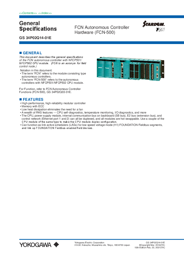
<<Contents>> <<Index>>
General Specifications
GS 34P02Q14-01E

FCN Autonomous Controller Hardware (FCN-500)

 GENERAL
This document describes the general specifications of the FCN autonomous controller with NFCP501/ NFCP502 CPU module. (FCN is an acronym for field control node.)
Notation in this document: � The term "FCN" refers to the module consisting type
autonomous controllers. � The term "FCN-500" refers to the autonomous
controllers with NFCP501/NFCP502 CPU module.
For Function, refer to FCN Autonomous Controller Functions (FCN-500), GS 34P02Q03-01E.
 FEATURES
� High-performance, high-reliability modular controller � Memory with ECC � Low heat dissipation eliminates the need for a fan � A wealth of RAS features -- CPU self-diagnostics, temperature monitoring, I/O diagnostics, and more � The CPU, power supply module, internal communication bus on backboard (SB bus), E2 bus (extension bus), and
control network (Ethernet port 1 and 2) can all be duplexed, and all modules are hot-swappable. Use a couple of the CPU module of the same type to make the CPU module duplex configuration. � Can function as link active schedulers (LASs) for low-speed voltage mode (H1) FOUNDATION Fieldbus segments, and link up FOUNDATION Fieldbus-enabled field devices.

Yokogawa Electric Corporation 2-9-32, Nakacho, Musashino-shi, Tokyo, 180-8750 Japan

GS 34P02Q14-01E �Copyright Mar. 2016(YK) 15th Edition Feb. 22, 2021(YK)

<<Contents>> <<Index>>

2

 CONFIGURATION
An FCN-500 consists of the following:
� Base module � Power supply module � CPU module � E2 bus interface module (extending the unit) (*1) � SB bus repeat module (extending the SB bus to connect an extension unit) (*1) � I/O modules
*1: SB bus repeat module and E2 bus interface module can not be used together.

There are four types of base module. - NFBU200 base module (long):
- N2BU051 base module (short): - NFBU050 base module (short): - N2BU030 base module (compact):

Control unit and extension unit sharing, duplexed power supply possibility Control unit and extension unit sharing Control unit only, for low power Control unit and extension unit sharing

l Control unit alone The control unit is unit with CPU module. The maximum number of I/O modules that can be implemented depends on the type of base module and the number of CPUs.
Maximum I/O Module Configurations

Base Module NFBU200 base module (long) N2BU051 base module (short) NFBU050 base module (short) N2BU030 base module (compact)

Unit Configuration Control unit alone Control unit alone Control unit alone Control unit alone

Standard Max. 8 modules Max. 3 modules Max. 3 modules Max. 1 module

Duplexed (*1) Max. 6 modules Not applicable (*2) Not applicable (*2) Not applicable (*2)

*1: When CPU modules are duplexed *2: Neither power supply nor CPU modules can be duplexed on N2BU051, NFBU050 or N2BU030.

Example: Standard control unit
Ethernet

DMY PWM CPU IOM IOM IOM IOM IOM IOM IOM IOM

Unit:1 Slot 1 2 3 4 5 6 7 8
Example: Control unit with duplexed CPU and power supply modules

9 10
F01E.ai

Ethernet

PWM PWM CPU CPU IOM IOM IOM IOM IOM IOM

Unit:1 Slot 1 2 3 4 5 6 7 8 9 10
F02E.ai

All Rights Reserved. Copyright � 2016, Yokogawa Electric Corporation

GS 34P02Q14-01E Apr. 18, 2018-00

<<Contents>> <<Index>>

3

Example: Short control unit

Ethernet

PWM CPU IOM IOM IOM

Example: Compact control unit

Unit:1 Slot 1 2 3 4 5
F10E.ai
Ethernet

PWM CPU IOM

Slot 1 2 3

Abbreviation PWM CPU IOM N2EB NFSB DMY

Description Power supply module CPU module I/O module E2 bus interface module SB bus repeat module Dummy cover for power supply Module Slot

F31E.ai

l Unit extension with E2 bus Up to eight extension units can be connected to the control unit using the E2 bus interface modules. Two ports of the E2 bus interface module mounted on the control unit can be connected to extension units as separate lines. The maximum number of extendable units that can be connected is a maximum of 8 units in total of two lines. Three types of base modules (NFBU200, N2BU051 or N2BU030) can be used as control unit and extension unit. By installing two E2 bus interface modules in each base module, it is possible to duplex E2 bus. (*1)
Connect each E2 bus interface module with UTP straight cable (CAT 5e or higher). The distance between units can be extended up to 100 m.
*1: When using the compact base module for the control unit, it is not possible to duplex the communication lines.
Maximum I/O Module Configurations

Base Module NFBU200 base module (long)

Unit Configuration
Control unit with 8 extension units (*2)

Standard Max. 79 modules

Duplexed (*1) Max. 68 modules

Note: NFCP501/NFCP502 CPU module style S2 or later is required to use the E2 bus interface module. *1: When CPU and E2 bus interface modules are duplexed. *2: When NFBU200 base modules are used in all extension units.

Extension of Transmission distance by Optical fiber The transmission distance between units can be extended by converting the system from UTP straight cable to fiber optic cable with third party's media converters. Only Layer 1 (Physical Layer) media converters which simply convert packets from electric signal to optical signal can be used for the E2 bus. Refer to the verified media converter information and precaution on Yokogawa Partner Portal STARDOM site when choosing the model.
https://partner.yokogawa.com/global/member/rtu/os/index.htm#tab04

All Rights Reserved. Copyright � 2016, Yokogawa Electric Corporation

GS 34P02Q14-01E Feb. 25, 2019-00

<<Contents>> <<Index>>

4

Example: Standard control unit + 8 extension units with E2 bus interface modules / 1 lines
Ethernet

DMY PWM CPU IOM IOM IOM IOM IOM IOM IOM N2EB

Upstream unit

DMY PWM IOM IOM IOM IOM IOM IOM IOM IOM IOM N2EB

Unit:1 Slot 1 2 3 4 5 6 7 8 9 10 Unit:2 Slot 1 2 3 4 5 6 7 8 9 10 Unit:3 Slot 1 2 3 4 5 6 7 8 9 10

DMY PWM IOM IOM IOM IOM IOM IOM IOM IOM IOM N2EB

Downstream unit

DMY PWM IOM IOM IOM IOM IOM IOM IOM IOM IOM N2EB

PWM PWM CPU CPU IOM IOM IOM IOM N2EB N2EB

Unit:9 Slot 1 2 3 4 5 6 7 8 9 10
F32E.ai
Example: Control unit with duplexed CPU modules, power supply modules, and E2 bus + 8 extension units / 1 lines
Unit:1
Unit:2
Unit:3

PWM PWM IOM IOM IOM IOM IOM IOM IOM IOM N2EB N2EB

PWM PWM IOM IOM IOM IOM IOM IOM IOM IOM N2EB N2EB

PWM PWM IOM IOM IOM IOM IOM IOM IOM IOM N2EB N2EB

Unit:9

F38E.ai

All Rights Reserved. Copyright � 2016, Yokogawa Electric Corporation

GS 34P02Q14-01E Jul. 1, 2018-00

<<Contents>> <<Index>>

5

Example: Control unit with duplexed CPU modules, power supply modules, and E2 bus + 8 extension units / 2 lines
Note: The CPU module, power supply module, and E2 bus can be made duplex individually, when required.
Ethernet

PWM PWM CPU CPU IOM IOM IOM IOM N2EB N2EB

Upstream unit

Upstream unit

PWM PWM IOM IOM IOM IOM IOM IOM IOM IOM N2EB N2EB PWM PWM IOM IOM IOM IOM IOM IOM IOM IOM N2EB N2EB

Downstream unit

Unit:1 Slot 1 2 3 4 5 6 7 8 9 10

Unit:2 Slot 1 2 3 4 5 6 7 8 9 10

Unit:8 Slot 1 2 3 4 5 6 7 8 9 10

Unit:3 Slot 1 2 3 4 5 6 7 8 9 10

Unit:9 Slot 1 2 3 4 5 6 7 8 9 10

PWM PWM IOM IOM IOM IOM IOM IOM IOM IOM N2EB N2EB PWM PWM IOM IOM IOM IOM IOM IOM IOM IOM N2EB N2EB

Downstream unit

PWM PWM IOM IOM IOM IOM IOM IOM IOM IOM N2EB N2EB

Unit:7 Slot 1 2 3 4 5 6 7 8 9 10

F33E.ai

Example: Mixed base module configuration, E2 bus + 8 extension units / 2 lines Note: Three kinds of base modules (NFBU200, N2BU051 or N2BU030) can be arranged according to the number of I/O points and installation environment required for the control unit and extension unit.

Unit:1

DMY PWM CPU IOM IOM IOM IOM IOM IOM IOM N2EB

PWM IOM IOM IOM IOM N2EB

PWM IOM IOM IOM IOM N2EB

Unit:2

Unit:8

Unit:3

Unit:9

PWM IOM IOM N2EB

PWM IOM IOM N2EB

DMY PWM IOM IOM IOM IOM IOM IOM IOM IOM IOM N2EB

Unit:7 All Rights Reserved. Copyright � 2016, Yokogawa Electric Corporation

F39E.ai
GS 34P02Q14-01E Jul. 1, 2018-00

<<Contents>> <<Index>>

6

l Unit extension with SB bus Up to two extension units can be connected using the SB bus repeat modules. The SB bus repeat module can be mounted on the base module (NFBU200 only). By installing two SB bus repeat modules on each base module, it is possible to duplex the SB bus. Connect each SB bus repeat module with a dedicated cable.
Maximum I/O Module Configurations

Base Module NFBU200 base module (long)

Unit Configuration
Control unit with 2 extension units

Standard Max. 25 modules

Duplexed (*1) Max. 20 modules

*1: When CPU and SB bus repeat modules are duplexed.

Example: Standard control unit + 2 extension units with SB bus reprat modules
Ethernet

Example: Control unit with duplexed CPU modules, power supply modules, and SB bus + 2 extension units
Note: The CPU module, power supply module, and
SB bus can be made duplex individually, when
required.

Ethernet

DMY PWM CPU IOM IOM IOM IOM IOM IOM IOM NFSB

PWM PWM CPU CPU IOM IOM IOM IOM NFSB NFSB

Unit:1 Slot 1 2 3 4 5 6 7 8 9 10

Unit:1 Slot 1 2 3 4 5 6 7 8 9 10

DMY PWM IOM IOM IOM IOM IOM IOM IOM IOM IOM NFSB

PWM PWM IOM IOM IOM IOM IOM IOM IOM IOM NFSB NFSB

Unit:2 Slot 1 2 3 4 5 6 7 8 9 10

Unit:2 Slot 1 2 3 4 5 6 7 8 9 10

DMY PWM IOM IOM IOM IOM IOM IOM IOM IOM IOM NFSB

PWM PWM IOM IOM IOM IOM IOM IOM IOM IOM NFSB NFSB

Unit:3 Slot 1 2 3 4 5 6 7 8 9 10
F03E.ai

Unit:3 Slot 1 2 3 4 5 6 7 8 9 10
F04E.ai

All Rights Reserved. Copyright � 2016, Yokogawa Electric Corporation

GS 34P02Q14-01E Jul. 1, 2018-00

<<Contents>> <<Index>>

7

 INSTALLATION REQUIREMENTS

Item

Operation Ambient temperature
Transportation/storage

Ambient humidity

Operation Transportation/storage

Rate of change in temperature

Operation Transportation/storage

Dust

Protection class

Resistance to corrosive gases

Resistance to vibration

Resistance to shock

Altitude

Electric field

Noise

Magnetic field

Electrostatic discharge

Grounding

Cooling

Specification

FCN-500 (NFCP501-0/NFCP502 -0
Standard Type)

FCN-500 (NFCP501-1/NFCP502-1 Extended Temperature range Type)

0� to 55�C

-20� to 70�C (*1)

-40� to 85�C

5 to 95 %RH (no condensation)

5 to 95 %RH (no condensation)

Within �10�C/h

Within �20�C/h

0.3 mg/m3 or less

IP20

ANSI/ISA S71.04 Class G2 (Standard) (ANSI/ISA S71.04 Class G3, option)

0.15 mm P-P (5 to 58 Hz), 1 G (58 to 150 Hz)

15 G, 11 ms (during power-off, for sine half-waves in XYZ-directions)

2000 m or less

3 V/m or less (26 MHz to 1 GHz)

30 A/m (AC) or less, 400 A/m (DC) or less

4 kV or less contact discharge, 8 kV or less aerial discharge

Apply the grounding system which is defined by the rules and standards of the country or the region.

Natural air cooling

*1: It depends on I/O modules. Refer to " I/O MODULES" for details

All Rights Reserved. Copyright � 2016, Yokogawa Electric Corporation

GS 34P02Q14-01E Jan. 22, 2019-00

<<Contents>> <<Index>>

8

 COMPLIANT STANDARDS

Safety standards (*1) (*4) (*5)(*8)
EMC standards (*8)

Item CSA
CE Marking Low Voltage Directive EAC Marking Morocco Compliance Marking (C Marking)
CE Marking EMC Directive RCM KC Marking EAC Marking Morocco Compliance Marking (C Marking)
US (FM) Nonincendive (*1)

Standards CAN/CSA-C22.2 No.61010-1 CAN/CSA-IEC 61010-2-201 CAN/CSA-C22.2 No.61010-2-030
EN 61010-1 EN 61010-2-201 EN 61010-2-030
CU TR 004
NM EN 61010 1 NM EN 61010 2 201 NM EN 61010 2 030 NM EN 60825 1
EN 55011 Class A Group 1 (emission) (*7) EN 61000-6-2 (immunity) (*1) (*2) (*6) EN 61000-3-2 EN 61000-3-3 (*3)
EN55011 Class A Group 1 (*7)
Korea Electromagnetic Conformity Standard
CU TR 020
NM EN 55011 Class A Group 1 (*7) NM EN 61000 6 2 NM EN 61000 3 2 NM EN 61000 3 3
Class I Division 2, Groups A, B, C, D T4 FM 3600:2018 FM 3611:2018 FM 3810:2018 ANSI/UL 121201:2017 ANSI/UL 61010-1:2012 ANSI/UL 61010-2-30:2012 ANSI/UL 61010-2-201:2014

Standards for Hazardous Location Equipment (*8) (*9)
Marine Standards (*13) (*14) Restriction of Hazardous Substances (*8)

ATEX Type "n" (*10) (*11)
Canada (CSA) Non-Incendive (*1)
IECEx Type "n" (*1) Emirates Conformity Assessment Scheme (ECAS-Ex) Type "n" (*1) BV (Bureau Veritas) LR (Lloyd's Register) RoHS Directive (*15) UAE RoHS Directive

II 3 G Ex nA nC II C T4 Gc X (*12) EN IEC 60079-0:2018 EN 60079-15:2010
Class I Division 2, Groups A, B, C, D T4 C22.2 No.213-17 CAN/CSA-C22.2 No.61010-1-12 CAN/CSA-C22.2 No.61010-2-030-12 CAN/CSA-IEC 61010-2-201:14
Ex nA IIC T4 Gc IEC 60079-0 Ed. 7.0 (2017) IEC 60079-15:2010
Ex nA IIC T4 Gc IEC 60079-0 Ed. 7.0 (2017) IEC 60079-15:2010
Rules for the Classification of Steel ships-January 2018 edition, Part C Chapter 3 Section 6 (EC Code: 31)
Type Approval System Test Specification Number 1 July 2015 (Environmental categories ENV2)
EN IEC 63000:2018
UAE Cabinet Decision No. 10 of 2017

*1: For the rack-mountable devices, DIN rail-mountable devices, and wall-mountable devices to meet the Safety Standards and EMC Standards, the devices must be installed in a lockable metal cabinet. The cabinet must conform to IEC/EN/CSA 61010-2-201 or provide degrees of protection IP3X or above and IK09 or above.
*2: For lightning surge immunity, a device such as a lightning arrester needs to be installed externally. Some module can select a pressure clamp terminal block with surge absorber. For details, see "Terminal Block" (GS 34P02Q41-01E).
*3: The specified magnitude of the voltage drop determined by the cable wiring length needs be met. *4: For ensuring the FCN hardware to satisfy the safety standards, the dedicated breakers in the power supply side must be
installed and conform to the following specifications. � [CSA] CSA C22.2 No.5 or UL 489 � [CE Marking] EN 60947-1 and EN 60947-3
*5: To be compliant with these standards, the FCN's cable which is drawn out from the metal, needs to be used the VW-1 class or more of flame-retardant cable.
*6: When using the NFLP121, mount one (A1193MN) ferrite core on the NFLP121 side of the PROFIBUS cable to meet the EMC standards.
*7: A Class A hardware device is designed for use in the industrial environment. Please use this device in the industrial environment only.

All Rights Reserved. Copyright � 2016, Yokogawa Electric Corporation

GS 34P02Q14-01E Feb. 22, 2021-00

<<Contents>> <<Index>>

9

*8: For modules conforming to each standards, refer to the section "I/O Module" and the table "List of FCN's Modules and Compliant Standards, Installation Limitations" of this document.
*9: Refer to TI 34P02Q91-01E for the products meeting NI.
*10: When FCN is used under the ATEX Type "n" environment, the Instruction Manual, "Explosion Protection of FCN/FCJ Products" (IM 34P02Q11-02E) is required for safer installation and wiring.
*11: To be compliant with these standards, the FCN hardware needs to be installed in a lockable metal cabinet of IP54 or higher
protection rating.
*12: This marking is the explosion-proof specification for FCN. The marking of each module is either " II 3G Ex nA II C T4 Gc X" or " II 3G Ex nA nC II C T4 Gc X". Symbol `X' denotes the specific condition of use. See "Explosion Protection of FCN/ FCJ Products" (IM 34P02Q11-02E) for detail.
*13: Refer to TI 34P02Q93-01E for the products meeting the Marine Standards.
*14: Please inquire about marine standards conformity to each country/region.
*15: Including the confirmation of 10 restricted substances defined in the Commission Delegated Directive(EU) 2015/863 amending Annex II to Directive 2011/65/EU.

In relation to the CE Marking, the manufacturer and the authorised representative for the Product in the EEA are indicated below:
� Manufacturer: Yokogawa Electric Corporation (2-9-32 Nakacho, Musashino-shi, Tokyo 180-8750, Japan)
� Authorised representative in the EEA: Yokogawa Europe B.V. (Euroweg 2, 3825 HD Amersfoort, The Netherlands)

"Administration on the Control of Pollution Caused by Electrical and Electronic Products" in the People's Republic of China.
The Product information required by the law is disclosed in the Yokogawa's website. Please refer to the following site.
http://www.yokogawa.com/dcs/CNRoHS/

This instrument is intended to be sold and used only as a part of equipment which is excluded from EU WEEE (Waste
Electrical and Electronic Equipment) Directive, such as large-scale stationary industrial tools, a large-scale fixed installation and so on, and therefore, subjected to the exclusion from the scope of the WEEE Directive.

All Rights Reserved. Copyright � 2016, Yokogawa Electric Corporation

GS 34P02Q14-01E Feb. 22, 2021-00

<<Contents>> <<Index>>

10

 BASE MODULE
A base module is a chassis on which various function modules such as CPU, power supply, E2 bus interface, SB bus
repeat, and I/O modules are mounted to configure a control unit or extension unit.

l Features Feature of Base Modules

Type Long Short Compact

Model NFBU200 N2BU051 NFBU050 N2BU030

Power Supply Slots 2 slots 1 slot 1 slot 1 slot

I/O Slots 10 slots 5 slots 5 slots 3 slots

SB Bus (Internal Backboard Bus) Duplex Duplex Single Duplex

Number of Mountable Modules on Control unit alone

Usage Control Unit

Model
NFBU200
N2BU051 NFBU050 N2BU030

Power Supply Modules
Single or Duplexed
Single Single Single

CPU Modules (*1) Single Duplex Single Single Single

Extension bus Module -

I/O Modules max 8 modules max 6 modules max 3 modules max 3 modules max 1 module

Number of Mountable Modules with E2 bus interface module

Usage

Model

Power Supply Modules CPU Modules (*1)

Control Unit
Extension Unit

NFBU200
N2BU051 N2BU030 NFBU200 N2BU051 N2BU030

Single or Duplex
Single Single Single or Duplex Single
Single

Single Duplex Single Single
-

E2 bus Interface Modules Single Duplex Single Duplex Single Duplex Single Single Duplex Single Duplex Single Duplex

I/O Modules
max 7 modules max 6 modules max 5 modules max 4 modules max 2 modules max 1 module
none max 9 modules max 8 modules max 4modules max 3 modules max 2 modules max 1 module

Number of Mountable Modules with SB bus repeat module

Usage

Model

Power Supply Modules CPU Modules (*1)

Control Unit NFBU200

Single or Duplex

Single Duplex

Extension Unit

NFBU200

Single or Duplex

-

*1: Two slots are occupied for at least one CPU module in the control unit.

SB bus Repeat Modules Single Duplex Single Duplex Single Duplex

I/O Modules
max 7 modules max 6 modules max 5 modules max 4 modules max 9 modules max 8 modules

All Rights Reserved. Copyright � 2016, Yokogawa Electric Corporation

GS 34P02Q14-01E Jan. 22, 2019-00

<<Contents>> <<Index>>

11

l Model and Suffix Codes Base Module (long)

Model Suffix Codes

NFBU200 -S
0 1
5 6 E F

Description Base module (long) Standard type 19-inch rack-mounted DIN rail-mounted Basic type with no explosion protection With ISA Standard G3 option and no explosion protection Basic type with explosion protection With ISA Standard G3 option and explosion protection

Base Module (short)

Model Suffix Codes

N2BU051 -S
1 5 6 E F

Description Base module (short, for E2 bus) Standard type DIN rail-mounted Basic type with no explosion protection With ISA Standard G3 option and no explosion protection Basic type with explosion protection With ISA Standard G3 option and explosion protection

Model Suffix Codes

NFBU050 -S
1 5 6 E F

Description Base module (short) Standard type DIN rail-mounted Basic type with no explosion protection With ISA Standard G3 option and no explosion protection Basic type with explosion protection With ISA Standard G3 option and explosion protection

Base Module (compact)

Model Suffix Codes

N2BU030 -S
1 5 6 E F

Description Base module (compact) Standard type DIN rail-mounted Basic type with no explosion protection With ISA Standard G3 option and no explosion protection Basic type with explosion protection With ISA Standard G3 option and explosion protection

Optional Accessories

Model

NFDCV01 NFDCV02

Description Dummy cover for I/O module slot Dummy cover for power supply module slot

All Rights Reserved. Copyright � 2016, Yokogawa Electric Corporation

GS 34P02Q14-01E Jan. 22, 2019-00

<<Contents>> <<Index>>

12

l Specifications

Model Weight

Item

Dimensions (W x H x D)

Mounting

Maximum power consumption

5 V 24 V

Self-con sumption
Self-con sumption

NFBU200-S0 1.9 kg 482.6132.5 40.5 mm 19-inch rackmounted
0.4 A(max)
0

NFBU200-S1 1.0 kg
44013142.3 mm

Specification N2BU051-S1 0.6 kg
28313124.2 mm

DIN rail-mounted

NFBU050-S1 0.6 kg
28313124.2 mm

0.035 A

0.025 A

N2BU030-S1 0.5 kg 21013124.2 mm
0.035 A

l Dimensions

19-inch rack-mounted Model (NFBU200)

21.3

440

Unit: mm

482.6

8.45

465.7

40.5 17.6 18.4

132.5

37.7 57.1

DIN rail-mounted Model (NFBU200)

1.25 18

401.5

444

1.9

440.2

F05E.ai

18

Unit: mm

35 7 16

131

DIN rail-mounted Model (N2BU051, NFBU050)
Unit: mm

283 273 243.6

24.2(*1) 20.6 16.1

F06.ai

DIN rail-mounted Model (N2BU030)

Unit: mm

210 198 177.6

24.2(*1) 20.6
16.1

131

110

131

110

66.5

66.5

10.5

10.5

*1: Including mounting parts for DIN rail F11E.ai
All Rights Reserved. Copyright � 2016, Yokogawa Electric Corporation

*1: Including mounting parts for DIN rail F35E.ai
GS 34P02Q14-01E Jan. 22, 2019-00

<<Contents>> <<Index>>

 POWER SUPPLY MODULE
Mounted on a base module, a power supply module supplies steady power to other modules. Two power supply modules can be installed on a base module for redundancy.
This power supply module is equipped with input terminals for a 24 V DC power supply in addition to the main power input. The 24 V DC power input from these terminals are referred to as analog field power supply and fed to analog I/O modules to drive their field interface circuits and supply power to the connected field devices through the base module. However, when a 24 V DC power supply is needed for digital outputs, it must be supplied to individual terminals of the corresponding I/O modules. (For details, see the respective specifications for I/O modules.)

l Model and Suffix Codes

Model
Suffix Codes

NFPW441
-5
-E 0 1

Description Power supply module (100-120 V AC input)
Standard type with no explosion protection
Standard type with explosion protection
Basic type
With ISA Standard G3 option

Model
Suffix Codes

NFPW442
-5 0 1

Description Power supply module (220-240 V AC input)
Standard type with no explosion protection
Basic type
With ISA Standard G3 option

Model
Suffix Codes

NFPW444
-5
-E 0 1

Description Power supply module (24 V DC input)
Standard type with no explosion protection
Standard type with explosion protection
Basic type
With ISA Standard G3 option

13

l Pin Assignment
Power supply terminals (Models NFPW441 and 442)

Pin No. 1
2 3 4 5

Name

Signal

FLD24 V DC +

24 V analog field power supply (+) (*1)

FLD24 V DC �

24 V analog field power supply (-) (*1)

G

Ground of line filter

L Power input
N

Power supply terminals (Model NFPW444)

Pin No. 1
2 3 4 5

Name

Signal

FLD24 V DC +

24 V analog field power supply (+) (*1)

FLD24 V DC �

24 V analog field power supply (-) (*1)

G

Ground of line filter

+ Power input
�

*1: When analog I/O modules such as NFAI141 (with 2-wire transmitter), NFAI135, NFAI841, NFAB841, NFAI835, NFAF135, and NFAP135 are installed, an analog field power supply is needed.

Checking terminals

Pin No.

Name

1 +5 V-CHK

2 +24 V-CHK

3 GND

Signal Checking of 5 V system power
Checking of 24 V field power supply
Signal grounding

l LEDs

LED Indicator Color SYS-POWER Green
FLD-POWER Green

Description Lights when the 5 V system power output is on.
Lights when the 24 V field power supply is on.

All Rights Reserved. Copyright � 2016, Yokogawa Electric Corporation

GS 34P02Q14-01E Jan. 22, 2019-00

<<Contents>> <<Index>>

14

l Dimensions

Unit: mm

146.5

49.7

133

13.5

130

F07E.ai

l Specifications

Model

Item Rated input voltage

Input voltage range

Input frequency

Power supply input

Input current Fuse rating Rush current

Leak current

Withstanding voltage Insulation resistance

Insensitive momentary power-failure time
Rated output voltage

Rated output current

Peak current

Output

Total output
Startup time after power-on

Overvoltage protection

Overcurrent protection Rated input voltage

Input Input current

Analog field power supply

Fuse rating Rated output voltage

Output Rated output current

Overvoltage protection

Duplex configuration Weight

Dimensions (W x H x D)

Specification

NFPW441

NFPW442

100 to 120 V AC

220 to 240 V AC

80 to 132 V AC (rms)

170 to 264 V AC (rms)

47 to 66 Hz (Rating: 50/60 Hz)

Max. 1.4 A

Max. 0.7 A

3.15 A

3.15 A

Max. 80 A for 5 ms or less Max. 90 A for 5 ms or less

Max. 1 mA

3000 V AC for 1 minute

50 M at 500 V DC

NFPW444 24 V DC 21.6 to 31.2 V DC
Max. 3.3 A 6.3 A Max. 20 A
-- 500 V AC for 1 minute

10 ms (80%)

2 ms (90%)

+5.1 V DC 0 to 7.8 A 11.8 A 40 W (60 W peak) Max. 300 ms Max. 100 ms (after a power failure of 200 ms long with the rated input) Max. 7 V Min. 105% (shutdown after 4 to 14 seconds long overcurrent) 24 V DC �10% Max. 4 A 6.3 A Input voltage minus matching-diode drop 4 A 35 V Possible (when installed on base module NFBU200) 0.6 kg 49.7 x 130 x 146.5 mm

All Rights Reserved. Copyright � 2016, Yokogawa Electric Corporation

GS 34P02Q14-01E Jan. 22, 2019-00

<<Contents>> <<Index>>

15

 CPU MODULE
One CPU module is mounted in each control unit, or two for a duplexed CPU configuration. The CPU module runs a real-time operating system, supports programming languages compliant with the IEC 61131-3 international standard,
and serves as a Duolet virtual machine.

l Model and Suffix Codes

Model
Suffix Codes

NFCP501 NFCP502 -S -W
0 1
5 6 E F

Description CPU module for FCN (with 2 Ethernet ports) CPU module for FCN (with 4 Ethernet ports) With standard functions (*1) With extended functions (*1) Standard type With Extended Temperature range option Basic type with no explosion protection With ISA Standard G3 option and no explosion protection Basic type with explosion protection With ISA Standard G3 option and explosion protection

*1: The application portfolio which can be used differs by Standard function type and Extended function type. For details, refer to "FCN Autonomous Controller Functions (FCN-500)" (GS 34P02Q03-01E).
l Specifications

Item

Specification

Model

NFCP501

NFCP502

Style

S2 (*6)

Processor

Atom E3815 1.46 GHz

Main

256 MB with ECC

Memory

Static RAM 2 MB with ECC, backed up by battery

Secondary memory 1 GB on-board flash memory

External media

SD card 1 slot : SDHC (4 to 32GB) Class 10

Serial Port (*1)

1 RS-232-C port: D-sub 9 pins, male (*2)

Communication method

Full/Half duplex (software settings)

Synchronisation

Asynchronous

Baud rate

0.3, 1.2, 2.4, 4.8, 9.6, 14.4, 19.2, 28.8, 38.4, 57.6, or 115.2 kbps

Network interface

2 Ethernet ports: RJ45 modular jacks

4 Ethernet ports: RJ45 modular jacks

Baud rate

1000, 100, 10 Mbps, (1000BASE-T, 100BASE-TX, 10BASE-T)

I/O interface

SB bus (duplex)

RAS features

Watchdog timer, temperature monitor, etc.

Battery (*3)

1000 mAh graphite fluoride lithium battery (*4)

Display

3 LEDs for CPU status indication, 2 LEDs for Ethernet status indication, 1 LED for SD LED, 1LED for EXEC LED

Switches

RESET switch, SHUT DOWN switch, FUNC switch, EXEC switch

Ptotection

CPU cover (with the hole for wire lock)

Power supply

Supply voltage

5 V DC �5%

Current consumption

Max. 1200 mA

Max. 1700 mA

Duplex configuration Possible (*5)

Weight

0.9 kg

Dimensions (W x H x D)

65.8 x 130 x 149.3 mm

Size

Occupying slots

2

*1: A serial port cannot be used when CPU modules are configured in redundancy. *2: Connectors are fastened using inch screw threads (No. 4-40 UNC).
*3: With battery exhaustion detection function
*4: A battery is exchangeable at on-line.
*5: Use a couple of the CPU module of the same type (same Model, same suffix codes and same system software version) for the CPU module duplex configuration. A combination of CPU module styles S1 and S2 is possible.
*6: The CPU module NFCP501/NFCP502 style S2 or later is required to use the E2 bus interface module.

All Rights Reserved. Copyright � 2016, Yokogawa Electric Corporation

GS 34P02Q14-01E Jan. 22, 2019-00

<<Contents>> <<Index>>

l Appearances

RESET switch SHUTDOWN switch Serial port 1 FUNC switch EXEC switch

NFCP501-S05

S1

HRDY RDY CTRL

SERIAL

RESET
SHUT DOWN EXEC LED
0 FUNC

EXEC BATTERY

NFCP501-S05

S1

HRDY RDY CTRL

SERIAL

CPU cover

SD card slot Ethernet port 2 Ethernet port 1

SD NETWORK 2
SD LED
1 CN1

NETWORK 2
1

SD LED

F080103.ai
Figure NFCP501 (Left: removed CPU cover, Right: mounted CPU cover)

RESET switch

NFCP502-S05

S1

HRDY RDY CTRL

SHUTDOWN switch Serial port 1 FUNC switch EXEC switch
Ethernet port 4 Ethernet port 3

SERIAL
NETWORK 4 3

RESET SHUT DOWN EXEC LED 0 FUNC EXEC BATTERY
SD

SD card slot

2

SD

Ethernet port 2

LED

1

Ethernet port 1

CN1

NFCP502-S05

S1

HRDY RDY CTRL

SERIAL

CPU cover

NETWORK 4 3
2 1

SD LED

F0804.ai
Figure NFCP502 (Left: removed CPU cover, Right: mounted CPU cover)

16

All Rights Reserved. Copyright � 2016, Yokogawa Electric Corporation

GS 34P02Q14-01E Jan. 22, 2019-00

<<Contents>> <<Index>>

l Pin Assignments of CPU Module's Serial Port
Table Connector Pin Assignment (D-sub 9-pin, male)

Pin No
1 2 3 4 5 6 7 8 9

Signal name CD RD SD ER SG DR RS CS --

Function
Data channel receiving carrier detection Receiving data Transmission data Data terminal ready Signal ground Data set ready Transmission request Transmission enabled Not used

1 6
2 7
3 8
4 9
5 F13E.ai
Figure Pin Position (Front View)

l Switches
RESET Switch Restart the CPU module.
SHUT DOWN Switch Terminate the CPU module.
FUNC Switch Select backup and restore function
EXEC Switch Execute backup and restore function.

l CPU Cover Prevent the erroneous operation or mischief of various switches and SD card.

Hole for wire lock Secure the CPU cover by a wire.
Recommended wire diameter:

1 mm

17

l LEDs

Operation Status Indicators

LED Indicator Color

HRDY

Green

RDY

Green

CTRL

Green

Description Lights when the hardware is normal.
Lights when the system is normal.
Lights when the control actions are carried out normally.

Ethernet Status Indicators (near RJ45 modular jacks)

LED Indicator Color

LINK

Green

ACT

Orange

Description Lights when the connection to a hub is normal.
Blinks when the transmission/ reception is on.

SD LED Indicators

LED Indicator Color

SD

Green

Description
Lights when the SD card is mounted. Blinks when the memory card is accessed.

EXEC LED Indicators

LED Indicator Color

EXEC

Green

Description
Lights when the maintenance function error. Blinks when the maintenance function is executed.

All Rights Reserved. Copyright � 2016, Yokogawa Electric Corporation

GS 34P02Q14-01E Jan. 22, 2019-00

<<Contents>> <<Index>>

18

l Dimensions

Unit: mm

149.3

65.8

6

129

13.5 ( 0.8 )

130

F0801E.ai
Figure NFCP501 (Demension)
Unit: mm

149.3

65.8

6

129

13.5 ( 0.8 )

130

Figure NFCP502 (Dimension)

F0802E.ai

All Rights Reserved. Copyright � 2016, Yokogawa Electric Corporation

GS 34P02Q14-01E Jan. 22, 2019-00

<<Contents>> <<Index>>

 E2 BUS INTERFACE MODULE
Used to connect a control unit to I/O extension units.
To duplex the E2 bus, install two E2 bus interface modules in each unit.
Each E2 bus interface module is connected to another via an UTP straight cable (CAT5e or higher).

l Model and Suffix Codes

Model
Suffix Codes

N2EB100 -S
5 E
0 1

Description E2 bus interface module Standard model With no explosion protection With explosion protection Basic type With ISA Standard G3 option

l Specifications

Item

Specification

Model

N2EB100

Baud rate

100 Mbps

Transmission distance Max. 100 m between each unit

Transmission cable UTP straight cable (CAT5e or higher)

Connector

RJ45 (ISO/IEC 8877)

Connection type

Daisy chain, Max. 2 lines

Extension units

Max. 8 units (9 units including a control unit and 2 lines)

Duplex configuration Possible

Power supply

Supply voltage
Current dissipation

5 V DC�5% Max. 500 mA

Weight

0.2 kg

Dimensions (W x H x D)

32.8 x 130 x 107.5 mm

Size

Occupying slots

1

Implementable base module

NFBU200 N2BU051 N2BU030

Single E2 bus

NFBU200: Slot No. 10 N2BU051: Slot No. 5 N2BU030: Slot No. 3

Slots to

be inst

NFBU200: Slot No. 9 and 10

alled in

Duplexed E2 bus

N2BU051: Slot No. 4 and 5 N2BU030: Control Unit: Unavailable
Extension unit :Slot No. 2

and 3

Ports

Master module
Slave module

Connectable two line with port1/port2
PORT1/UP: To Upstream (master side) PORT2/DOWN: To Downstream

Available CPU module

NFCP501/NFCP502 Style S2 or later

Unit number setting (rotary switch)

0: Invalid 1: Control unit (master module) 2 to 9: Unit number of extension unit
(slave module)

19

l LEDs

Operation Status Indicators

LED Indicator Color

RDY

Green

Description
Lights when the hardware is normal. Blinks when the rotary switch setting error

E2 bus Status Indicators

LED Indicator Color ACT (each port) Green
LNK (each port) Green

Description Lights when the transmission/ reception is on.
Lights when the connection is normal

l Appearances
N2EB100-S50 RDY

0

UNIT NO.

0:DISABLE

E2 BUS
ACT
LNK

PORT1 /UP

ACT

PORT2

LNK

/DOWN

E2 bus port 1
In case of master: Connect to the extension unit (line 1)
In case of slave: Connect to the upstream unit
E2 bus port 2
In case of master: Connect to the extension unit (line 2)
In case of slave: Connect to the downstream unit
F37E.ai

l Dimensions
Unit: mm

32.8
N2EB100-S50 RDY

0

UNIT NO.

0:DISABLE

E2 BUS
ACT
LNK

PORT1 /UP

ACT

PORT2

LNK

/DOWN

130

107.5 94

(13.5)

F36E.ai

All Rights Reserved. Copyright � 2016, Yokogawa Electric Corporation

GS 34P02Q14-01E Jan. 22, 2019-00

<<Contents>> <<Index>>

 SB BUS REPEAT MODULE
Used to connect a control unit to I/O extension units.
To duplex the SB bus, install two SB bus repeat modules in each unit.
Each SB bus repeat module is connected to another via a dedicated T-joint and cable.

l Model and Suffix Codes

Model
Suffix Codes
Option Codes

NFSB100 -S
5 E
0 1 /SBT01
/SBT02

Description SB bus repeat module for FCN Standard model With no explosion protection With explosion protection Basic type With ISA Standard G3 option With an SB bus T-joint With an SB bus T-joint with built-in terminator

Note: When connecting a control unit and extension units, install at both ends a T-joint with built-in terminator on each SB bus repeat module.

Models

NFSBT01 NFSBT02

Description SB bus T-joint SB bus T-joint with built-in terminator

Model
Suffix Codes

NFCB301 -C030 -C100 -C200 -C400 -C800

Description SB bus cable Cable length 30 cm Cable length 1 m Cable length 2 m Cable length 4 m Cable length 8 m

l Specifications

Item

Specification

Model

NFSB100

Transmission method Serial communication

Baud rate

128 Mbps

Transmission distance Max. 8 m per line

Extension units

Max. 2 units (3 units including a control unit)

Duplex configuration Possible

Power supply

Supply voltage
Current dissipation

5 V DC�5% Max. 500 mA

Weight

0.2 kg

Dimensions (W x H x D)

32.8 x 130 x 142.5 mm

Size

Occupying slots

1

Slots to be installed in

Slot No. 10 (for single SB bus) Slot Nos. 9 and 10 (for duplexed SB bus)

20

l LEDs

LED Indicator Color

STATUS

Green

SND

Green

RCV

Green

Description Lights when the hardware is normal. Lights when the transmission is on. Lights when the reception is on.

l Dimensions
Unit: mm

32.8

142.5 129 112 (WITHOUT T-CONN.)

(13.5)

130

F09E.ai

All Rights Reserved. Copyright � 2016, Yokogawa Electric Corporation

GS 34P02Q14-01E Jan. 22, 2019-00

<<Contents>> <<Index>>

21

 I/O MODULE

An autonomous controller FCN supports versatile I/O modules. For details, refer to the following general specifications:

� GS 34P02Q31-01E � GS 34P02Q35-01E � GS 34P02Q36-01E � GS 34P02Q55-01E � GS 34P02Q57-01E

Analog I/O Modules Digital I/O Modules Serial Communication Module Foundation Fieldbus Communication Module PROFIBUS-DP Communication Module

� GS 34P02Q58-01E � GS 34P02Q04-02E

CANopen Communication Module Turbomachinery Controller Overview (FCN-500/FCN-RTU)

 List of FCN's Modules and Compliant Standards, Installation Limitations

Table List of FCN's Modules and Compliant Standards, Installation Limitations (1/4)

Type
Base module Power supply module
CPU module E2 bus interface module SB bus repeat module
Analog I/O Modules (*1)

Model

Function

NFBU200 N2BU051 NFBU050 N2BU030 NFPW441 NFPW442 NFPW444 NFCP501
-0 -1 NFCP502 -0 -1

Base module (long) Base module (short, for E2 bus) Base module (short) Base module (compact) Power supply module (100 - 120 V AC input) Power supply module (220 - 240 V AC input) Power supply module (24 V DC input) CPU module for FCN (with 2 Ethernet ports) Standard type With Extended Temperature range option CPU module for FCN (with 4 Ethernet ports) Standard type With Extended Temperature range option

N2EB100 E2 bus interface module

Installation Limitations

Temperature Altitude

[�C]

[m]

-20 to +70

-20 to +70

-20 to +70

-20 to +70

0 to +55

0 to +55

-20 to +70 (*6)

-

0 to +55

-20 to +70

-

0 to +55

-20 to +70

-20 to +70

NFSB100
NFAI141 NFAV141
NFAI841
NFAB841
NFAI143 NFAI543 NFAV144 NFAV544 NFAT141 NFAR181
-S0 -S1 -S4 -S5 NFAI135
NFAI835
NFAP135 -S0 -S1 -S4 -S5
NFAF135

SB bus repeat module for FCN
Analog Input Module (4 to 20 mA, 16-channel, Non-Isolated) Analog Input Module (1 to 5 V: differential input, 16-channel, Non-Isolated) Analog I/O Module (4 to 20 mA input, 4 to 20 mA output, 8-channel input /8-channel output, Non-Isolated) Analog I/O Module (1 to 5 V input: differential input, 4 to 20 mA output, 8-channel input/8-channel output, Non-Isolated) Analog Input Module (4 to 20 mA, 16-channel, Isolated) Analog Output Module (4 to 20 mA, 16-channel, Isolated) Analog Input Module (-10 to +10 V, 16-channel, Isolated) Analog Output Module (-10 to +10 V, 16-channel, Isolated) TC/mV Input Module (16-channel, Isolated) RTD Input Module (12-channel, Isolated)
Basic type

0 to +55
-20 to +70 0 to +55
-20 to +70 (*7)
0 to +55
-20 to +70 -20 to +70 (*7) -20 to +70 (*3)
0 to +55 0 to +55
-
0 to +55

With Extended Temperature Range option

-20 to +70 (*5)

Analog Input Module (4 to 20 mA, 8-channel, Isolated channels)
Analog I/O Module (4 to 20 mA, 4-channel input/4-channel output, Isolated channels)
Pulse Input Module (8-channel, Pulse count, 0 to 10 kHz, Isolated channels)

-20 to +70 -20 to +70 (*7)
-

Basic type

0 to +55

With Extended Temperature Range option Frequency Input Module (8-channel, 0.1 Hz to 10 kHz, Isolated channels)

-20 to +70(*5) 0 to +55

2000

All Rights Reserved. Copyright � 2016, Yokogawa Electric Corporation

GS 34P02Q14-01E May 22, 2020-00

<<Contents>> <<Index>>

22

Table List of FCN's Modules and Compliant Standards, Installation Limitations (2/4)

Type

Model

NFDV151 NFDV161

NFDV532

Digital I/O Modules NFDV551
(*1)
NFDV561

NFDR541

-P

-T

Turbomachinery NFGS813

I/O Modules

NFGP813

NFLC121

NFLF111

-S0 -S1

Communication Modules

-S4 -S5

NFLP121

NFLR111

Pressure Clamp Terminal Block

NFLR121 NFTA4S NFTT4S NFTR8S NFTB5S NFTD5S
NFTI3S

Terminal Block Cable SB Bus T-joint Dummy Cover

NFTC4S
NFTF9S TAS40 TAS50 NFCB301 KMS40 KMS50 NFSBT01 NFSBT02 NFDCV01 NFDCV02 NFCCC01

Function
Digital Input Module (32-channel, 24 V DC, Isolated) Digital Input Module (64-channel, 24 V DC) Pulse Width Output Module (4-channel : Up Pulse/Down Pulse, 24 V DC, Isolated) Digital Output Module (32-channel, 24 V DC, Isolated) Digital Output Module (64-channel, 24 V DC) Relay Output Module (16-channel, Isolated) Standard type (24 V DC) Standard type (24 to 125 V DC/100 to 240 V AC) Servo Module High Speed Protection Module CANopen Communication Module(1-port, 10 kbps to 1 Mbps) Foundation fieldbus communication module (4-port)
Basic type

Installation Limitations

Temperature Altitude

[�C]

[m]

-20 to +70

0 to +55

0 to +55

-20 to +70 0 to +55

-20 to +70
(*3)(*4)

0 to +55 0 to +55 0 to +55
-
0 to +55

With Extended Temperature Range option

-20 to +70 (*5)

PROFIBUS-DP Communication Module (1-port, 9.6 kbps to 12 Mbps) RS-232-C Communication Module (2-port, 300 bps to 115.2 kbps) RS-422/RS-485 Communication Module (2-port, 300 bps to 115.2 kbps) Pressure Clamp Terminal Block for Analog (16-channel) Pressure Clamp Terminal Block for Thermocouple/mV (16-channel) Pressure Clamp Terminal Block for RTD (12-channel) Pressure Clamp Terminal Block for Digital Input (32-channel) Pressure Clamp Terminal Block for Digital Output (32-channel) Pressure Clamp Terminal Block for Isolated Analog Module and Pulse Module (for NFAI135, NFAP135, NFAF135: 8-channel, NFAI835: 4-channel input, 4-channel output) Pressure Clamp Terminal Block for Digital (16-channel, with dedicated connector, without surge absorber) Pressure Clamp Terminal Block for Foundation Fieldbus MIL Connector Terminal Block (40 Pole Plug Types) MIL Connector Terminal Block (50 Pole Plug Types) SB Bus Cable MIL Connector Cable (40 Pole Plug Types) MIL Connector Cable (50 Pole Plug Types) SB Bus T-joint SB Bus T-joint with Built-in Terminator Dummy Cover for I/O Module Slot Dummy Cover for Power supply Module Slot MIL Cable Connector Cover

0 to +55
0 to +55
-20 to +70 -20 to +70 0 to +55 -20 to +70 -20 to +70 -20 to +70
-20 to +70
0 to +55
-20 to +70 -20 to +70 -20 to +70 0 to +55 -20 to +70 -20 to +70 0 to +55 0 to +55 -20 to +70 -20 to +70 -20 to +70

2000

All Rights Reserved. Copyright � 2016, Yokogawa Electric Corporation

GS 34P02Q14-01E Feb. 22, 2021-00

<<Contents>> <<Index>>

23

Table List of FCN's Modules and Compliant Standards, Installation Limitations (3/4)

Model
NFBU200 N2BU051 NFBU050 N2BU030 NFPW441 NFPW442 NFPW444 NFCP501
-0 -1 NFCP502 -0 -1 N2EB100 NFSB100
NFAI141
NFAV141
NFAI841
NFAB841 NFAI143 NFAI543 NFAV144 NFAV544 NFAT141 NFAR181
-S0 -S1 -S4 -S5 NFAI135 NFAI835 NFAP135 -S0 -S1 -S4 -S5 NFAF135

Safety

EMC

CSA CE EAC C CE RCM KC EAC C
XXX XXX X X X XXX XXX X X X XXX XXX X X X XXX XXX X X X XXX XX � X X X XXX XXX X X X XXX XXX X X X
XXX XXX X X X

XXX XXX X X X
XXX XXX X X X XXX XXX X X X XXX XXX X X X XXX XXX X X X XXX XXX X X X XXX XXX X X X XXX XXX X X X XXX XXX X X X XXX XXX X X X XXX XXX X X X X X X N.A. X X X X N.A.
X X X N.A. X X X X N.A.
XXX XXX X X X XXX XXX X X X
XXX XXX X X X
XXX XXX X X X

Explosion protection

Marine
(*10)

US (FM)
NI

ATEX
Type "n"

Canada
(CSA) NI

IECEx
Type "n"
ECAS-Ex

BV

LR

Type "n"

X

X

X

X

XX

X

X

X N.A. N.A. N.A.

X

X

X

X N.A. N.A.

X

X

X N.A. N.A. N.A.

X N.A. X N.A. X X

N.A. N.A. N.A. N.A. X X

X

X

X

X

XX

X

X

X

X N.A. N.A.

X

X

X

X

XX

X

X

X N.A. X X

X

X

X N.A. N.A. N.A.

XX
(*2)

X

XX
(*2)

X

XX

X

X

X N.A. N.A. N.A.

XX
(*2)

X

XX
(*2)

X

XX

X

X

X N.A. N.A. N.A.

X

X

X

X

XX

X

X

X

X

XX

X

X

X N.A. N.A. N.A.

X

X

X N.A. N.A. N.A.

X

X

X N.A. N.A. N.A.

X

X

X

X

XX

X

X

X N.A. X X

X

X

X

X

XX

X

X

X N.A. X X

X

X

X N.A. N.A. N.A.

Hazardous Substances

RoHS

UAE RoHS
(*8)

X

X

X

X

X

X

X

X

X

X

X

X

X

X

X

X

X

X

X

X

X

X

X

X

X

X

X

X

X

X

X

X

X

X

X

X

X

X

X

X

X

X

X

X

X

X

X

X

X

X

All Rights Reserved. Copyright � 2016, Yokogawa Electric Corporation

GS 34P02Q14-01E Feb. 22, 2021-00

<<Contents>> <<Index>>

24

Table List of FCN's Modules and Compliant Standards, Installation Limitations (4/4)

Model
NFDV151 NFDV161 NFDV532 NFDV551 NFDV561 NFDR541
-P
-T NFGS813 NFGP813 NFLC121 NFLF111
-S0 -S1 -S4 -S5 NFLP121 NFLR111 NFLR121 NFTA4S NFTT4S NFTR8S NFTB5S NFTD5S NFTI3S NFTC4S NFTF9S TAS40 TAS50 NFCB301 KMS40 KMS50 NFSBT01 NFSBT02 NFDCV01 NFDCV02 NFCCC01

Safety

EMC

CSA CE EAC C CE RCM KC EAC C

XXXXX XXXX XXXXX XXXX X � X X X XXX X XXXXX XXXX XXXXX XXXX

X N.A. X N.A. N.A. X X X N.A.

(*9)

(*9)

X X X X X XXX X

X X X X X XXX X

X X X X X XXX X

X X X X X XXX X

X X X X X XXX X

XXXXX XXXX XX XX X XXXX X X X X X XXX X XXXXX XXXX X X X N.A. X X X X N.A. X X X N.A. X X X X N.A. X X X X X XXX X X X X X X XXX X X X X X X XXX X XXXX X XXXX XXXX X XXXX XXXX X XXXX XXXX X XXXX XXXX X XXXX XXXX X XXXX XXXX X XXXX X X X X X XXX X X X X X X XXX X X X X X X XXX X X X X X X XXX X X X X X X XXX X

Explosion protection

Marine
(*10)

US (FM)
NI

ATEX
Type "n"

Canada
(CSA) NI

IECEx
Type "n"
ECAS-Ex Type "n"

BV

LR

X

X

X

X

XX

N.A. N.A. N.A. N.A. N.A. N.A.

N.A. N.A. N.A. N.A. N.A. N.A.

X

X

X

X

XX

N.A. N.A. N.A. N.A. N.A. N.A.

X

X (*9)

X

N.A. N.A. N.A.

X

X

X N.A. N.A. N.A.

N.A. N.A. N.A. N.A. N.A. N.A.

N.A. N.A. N.A. N.A. N.A. N.A.

N.A. N.A. N.A. N.A. N.A. N.A.

X

X

X N.A. X X

N.A. N.A. N.A. N.A. X X

X

X

X N.A. X X

X

X

X N.A. X X

X

X

X

X N.A. N.A.

X

X

X N.A. N.A. N.A.

X

X

X

X N.A. N.A.

X

X

X

X N.A. N.A.

X

X

X

X N.A. N.A.

X

X

X

X N.A. N.A.

X

X

X N.A. N.A. N.A.

X

X

X N.A. N.A. N.A.

X

X

X

X

XX

X

X

X

X

XX

X

X

X N.A. N.A. N.A.

X

X

X

X

XX

X

X

X

X

XX

X

X

X N.A. N.A. N.A.

X

X

X N.A. N.A. N.A.

X

X

X

X

XX

X

X

X

X

XX

X

X

X

X N.A. N.A.

Hazardous Substances

RoHS

UAE RoHS
(*8)

X

X

X

X

X

X

X

X

X

X

N.A. N.A.

X

X

X

X

X

X

X

X

X

X

X

X

X

X

X

X

X

X

X

X

X

X

X

X

X

X

X

X

X

X

X

X

X

X

X

X

X

X

X

X

X

X

X

X

X

X

X

X

X

X

X

X

X: Conforming XX: Conforming conditionally N.A.: Not applicable *1: To use modules as hazardous location equipment (non-incendive), use the specified pressure-clamp terminal blocks or MIL
connector cables (KMS40, KMS50) / MIL connector terminal blocks (TAS40 and TAS50) . *2: I/O modules with suffix code "with HART communication" do not conform to the explosion-proof standards. *3: When ambient temperature is higher than 55�C, a blank slot on one side is required to NFAV144 and NFDR541 modules. *4: When ambient temperature is higher than 55�C, available channels of NFDR541 are up to eight. *5: When ambient temperature is higher than 55�C, NFAR181, NFAP135 and NFLF111 modules cannot be installed in next
slot of the NFAI841. *6: When ambient temperature is higher than 55�C, NFPW444 module is restricted to 75% of rated output current. *7: NFAI841, NFAI543 and NFAI835 modules are restricted to the external load and module installation. Refer to "Table Module
Arrangement and Restrictions on Installation." *8: The products with the condition of not only adapted models on the table, but also manufactured from September, 2016,
compliant with UAE RoHS directive. Manufacturing month and year are marked on the each product. *9: NFDR541-P modules do not conform to CE Marking after July 22, 2017 due to non-conformity to RoHS. In areas
requiring CE marking, this module cannot be used except repair purpose only. *10: Please inquire about marine standards conformity to each country/region.

All Rights Reserved. Copyright � 2016, Yokogawa Electric Corporation

GS 34P02Q14-01E Feb. 22, 2021-00

<<Contents>> <<Index>>

25

 RESTRICTIONS AND PRECAUTIONS ON INSTALLATION
See Installation Guide for "STARDOM FCN/FCJ Installation Guide" (TI 34P02Q91-01E).

l Limitations of Installation for using in the wide temperature range (-20 to +70�C) environments
Main components of FCN (NFCP501/NFCP502�1, NFPW444, base modules, N2EB100) can operate in the wide temperature range (-20 to +70�C) environments.
The I/O Modules which are marked up on table "List of FCN's Modules and Installation Limitations" can operate in the wide temperature range environments.

70 �C 65 �C
55 �C

Ambient Temp.
( Operation )

I/O modules with suffix code -S0,-S1

Altitude 0 �C

70 �C 65 �C
55 �C

Ambient Temp.
( Operation )

I/O modules Wide Temperature model -20~70)

0 �C

Altitude

-20 �C

2000 m

-20 �C

2000 m

F21E.ai

All the I/O Modules Operation Range

Wide Temperature I/O Modules Operation Range

Figure Ambient Temperature and Altitude of I/O modules

l I/O Module Arrangement and Restriction for using ambiement temperature is higher than 55�C
Table Module Arrangement and Restrictions on Installation (when ambient temperature is higher than 55�C)

Model NFAI841
NFAI543

Left-side slot X (*1) X N.A. N.A. N.A.

NFDR541 NFAI835 NFAV144 NFPW444

X N.A.
X X X N.A. N.A. or NFPW444

X:

Any module (arbitrary)

*1:

Except NFAI841

Right-side slot

Limitations

X (*1)

External load (Analog Output): 200-750

N.A.

X

N.A.

External load (Analog Output): 0-400

X (*1)

Up to 12 channels External load (Analog Output): 0-400,

N.A.

Required a vacant slot on one side

X

Up to 8 channels

N.A.

External load (Analog Output): 200-750

X

External load (Analog Output): 200-500

N.A.

Required a vacant slot on one side

X

N.A. or NFPW444 /

Up to 75% of rated output current

NFCP501/NFCP502

N.A.: Blank or Not allowed

PWM CPU Vacant Slot NFAV144 IOM PWM CPU NFAV144 Vacant Slot IOM PWM CPU IOM IOM NFAV144

Slot 1 2 3 4 5

Slot 1 2 3 4 5

Slot 1 2 3 4 5

Figure Installation Example of using NFAV144

F20E.ai

All Rights Reserved. Copyright � 2016, Yokogawa Electric Corporation

GS 34P02Q14-01E Jan. 22, 2019-00

<<Contents>> <<Index>>

26

l Pulse Input Module with extend temp. option (NFAP135-S4, -S5)'s Ambient Temperature and Limitation of Installations depend on Input Mode
There are some conditions depending on usinginput mode and ambient temperature.

Table Input Mode, Ambient Temp. (operating) and Installation Requirement of NFAP135-S4, -S5

Input Mode (*1)

Ambient Temp. [�C]

Installation Requirement

Voltage pulse

-20 to +70 When ambient temperature is higher than 55�C, ensure space on both side (*2)

Dry contact pulse

-20 to +65 When ambient temperature is higher than 55�C, ensure space on both side (*2)

2-wire transmitter current pulse (4 to 20 mA)

with 200  shunt resistance
with 500  shunt resistance

-20 to +65 -20 to +55

When ambient temperature is higher than 55�C, ensure space on both side (*2)
Ensure space on one side (*2) Or use within 4 points or less

3-wire transmitter voltage pulse

-20 to +65 When ambient temperature is higher than 55�C, ensure space on both side (*2)

*1: Refer to Analog I/O Modules, GS 34P02Q31-01Es

*2: See Figure Installation Examples of using NFAP135

PWM CPU Vacant Slot NFAP135 Vacant Slot PWM CPU IOM Vacant Slot NFAP135

Slot 1

2 3 45

Slot 1 2 3

Figure Installation Example of using NFAP135

45
F12E.ai

l Limitations of Installation for NFAT141 (the combination of Thermocouple input and Pressure clamp terminal)
To keep the reference junction compensation accuracy (GS 34P02Q31-01E), make sure to meet the following conditions. The pressure clamp terminal should not be affected by radiated heat. � Do not install a heat-radiating unit beneath the NFAT141 installed unit. � Do not install NFAT141 in a place where airflow impinges directly. � Do not install NFAT141 next to the CPU modules (NFCP501/NFCP502), power supply modules (NFPW44x). � The installable modules next to the NFAT141 are as follows. When installing other than following I/O modules,
make an empty slot (one or more) in each side. Installable modules: NFAT141, NFAR181, NFAV141, NFAV144
l Limitations of Installation for Communication Modules � A total of up to eight NFLR111/NFLR121 can be installed for each FCN-500. � A total of up to eight NFLF111/NFLC121/NFLP121 (or up to eight duplexed pairs of NFLF111) can be installed for
each FCN-500.
l Limitations of Installation for I/O Modules When you install the following I/O modules, ensure that the required power volume does not exceed the rated power output of the power supply module. For the amount of power supply that each I/O module requires (5 V DC and 24 V DC), refer to the applicable general specifications.
l About Use of N2BU051, NFBU050 or N2BU030 � NFBU050 is dedicated to control unit. It cannot be used as extension unit. � SB bus repeat module cannot be mounted on N2BU051, NFBU050 or N2BU030. � E2 bus interface module cannot be mounted on NFBU050.
l Precaution on NFPW426 (Power Supply Module for FCN-RTU) NFPW426 (Power supply module for FCN-RTU) cannot be used for FCN-500. Only NFPW441, NFPW442 or NFPW444 can be used for FCN-500.

All Rights Reserved. Copyright � 2016, Yokogawa Electric Corporation

GS 34P02Q14-01E Jan. 22, 2019-00

<<Contents>> <<Index>>
 CABLE SPECIFICATIONS
The following describes the specifications required for the power and grounding cables used. For field signal wiring cables, see "Field Connections" (GS 34P02Q3001E).
l Applicable Cables Insulated cables for industrial equipment such as:
� 600 V polyvinyl chloride insulated wires (IV); JIS C3307
� Polyvinyl chloride insulated wires for electrical apparatus (KIV); JIS C3316
� 600 V grade heat-resistant polyvinyl chloride insulated wires (HIV); JIS C3317
� Heatproof vinyl insulated wires VW-1 (UL1015/ UL1007)
� Control cables (vinyl insulated vinyl sheath cable) (CVV); JIS C3401
l Recommended Sizes Power cable: AWG20 to 14 (0.5 to 2 mm2) with ring tongue terminal Grounding cable: AWG14 to 13 (2 to 2.6 mm2) with ring tongue terminal
l Recommended Solderless Terminals Power cable: Insulated M4 solderless terminals, 8.5 mm wide or less Grounding cable: Insulated M4 solderless terminal, 8.5 mm wide or less
Follow the specifications required by the M4 solderless terminals used.

27
 ORDERING INFORMATION
Specify the model and suffix codes.
 TRADEMARK ACKNOWLEDGMENTS
The names of corporations, organizations, products and logos herein are either registered trademarks or trademarks of Yokogawa Electric Corporation and their respective holders.

All Rights Reserved. Copyright � 2016, Yokogawa Electric Corporation Subject to change without notice.

GS 34P02Q14-01E May 22, 2020-00