File info: application/pdf · 18 pages · 419.47KB
Electromotoric actuators for valves
Manual adjuster, position and status indication (LED) Optional functions with auxiliary switches, potentiometer, function module, stem heating. 2 Siemens CE1N4501en Smart Infrastructure 2020-11-26 Use Electromotoric act…
Electromotoric actuators for valves - Siemens Download Center
Manual adjuster, position and status indication (LED). ○ Optional functions with auxiliary switches, potentiometer, function module, stem.
Full PDF Document

If the inline viewer fails, it will open the original document in compatibility mode automatically. You can also open the file directly.
Extracted Text
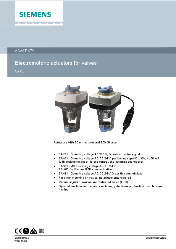
ACVATIXTM
Electromotoric actuators for valves
SAX..

Actuators with 20 mm stroke and 800 N force
 SAX31.. Operating voltage AC 230 V, 3-position control signal  SAX61.. Operating voltage AC/DC 24 V, positioning signal 0...10V, 4...20 mA
With position feedback, forced control, characteristic changeover  SAX61../MO operating voltage AC/DC 24 V,
RS-485 for Modbus RTU communication  SAX81.. Operating voltage AC/DC 24 V, 3-position control signal  For direct mounting on valves; no adjustments required  Manual adjuster, position and status indication (LED)  Optional functions with auxiliary switches, potentiometer, function module, stem
heating

CE1N4501en 2020-11-26

Smart Infrastructure

Use
Electromotoric actuators to operate Siemens 2-port and 3-port valves, types V..F21.., V..F22.., V..F31.., V..F32.., V..F40.., V..F41.., V..F42.., V..F52.., and V..F53.. with 20 mm stroke as control and safety shut-off valves in heating, ventilation and air conditioning systems.

Functions

Function

Description

3-position control

A 3-position signal controls the actuator via connection terminals Y1 or Y2. The desired position is transmitted to the valve.

Modulating control

The modulating positioning signal provides stepless motor control. The positioning signal range (DC 0...10 V / DC 4...20 mA / 0...1000 ) corresponds to the positioning range (closed...open, or 0...100% stroke) in a linear manner.

Positioning signal and characteristic changeover

Setting with DIL switch. Factory setting:  Characteristic curve: log = Equal percentage (switch set to Off)  Positioning signal: DC 0...10 V (switch set to Off)

Position feedback U

Signal returned to acquire the position via input.

Forced control (Z-mode)

Forced control helps override automatic mode and is implemented via higher control.

Calibration

Carry out during initial commissioning. The actuator drives to the top or bottom end position; the measured values are saved.

Valve seat detection

The actuators have power-dependent seat detection. After calibration, the exact valve stroke is stored in the actuator's memory.

Foreign body detection

After clogging is detected, three attempts are made to get past clogging. If unsuccessful, the actuator continues to follow the positioning signal only within a limited range, and the LED blinks red.

Modbus RTU (RS-485), not galvanically isolated

Setpoint 0...100 % valve position Actual value 0...100 % for valve position Override control Open / Close / Min / Max / Stop Setpoint monitoring and backup mode

Type SAX31.., SAX81.. SAX61..
SAX61.., SAX61../MO
SAX61../MO

2 Siemens Smart Infrastructure

CE1N4501en 2020-11-26

Type summary

Type

Item NO.

Stroke Positionin Operating Positioning Spring Positionin LED Manual Auxiliary

g force voltage

signal

return g time

adjustment functions

time

3)

SAX31.00 1) SAX31.03 1)

S55150-A105 S55150-A106

120 s

AC 230 V 3-position

-

-

SAX61.03 2)

S55150-A100

DC ...10 V

SAX61.03U 2) S55150-A100-A100

DC 4...20 mA

20 mm 800 N

0...1000

-

SAX61.03/MO 2) S55150-A140

AC 24 V Modbus RTU

SAX81.00 2)

S55150-A102

DC 24 V

30 s

4)

Yes

Push and fix

5)

120 s

SAX81.03 2) SAX81.03U 2)

S55150-A103 S55150-A103-A100

3-position

-

-

30 s

1) Approbation: CE 2) Approbation: CE, UL 3) Not designed for continuous operation. 4) Position feedback, forced control, characteristic changeover 5) Position feedback, forced control

Scope of delivery Actuators, valves and accessories are supplied in individual packs.

Accessories/spare parts

Electrical accessories

Type

Auxiliary switch ASC10.51

Item No.

S55845-Z103

SAX31.. SAX61.. SAX61../MO SAX81..

Max. 2

Potentiometer ASZ7.5

Function module AZX61.1

S55845-Z106

S55845-Z107

Max. 2

Max. 1

-

-

Max. 1

-

Max. 1

-

Stem heating element ASZ6.6
S55845-Z108
Max. 1

Mechanical accessory
Type

Item No.

Weather shield ASK39.1 1)
S55845-Z109

Siemens Smart Infrastructure

3 CE1N4501en
2020-11-26

Ordering (example)

Type SAX81.03 ASZ7.5

Stock number S55150-A103 S55845-Z106

Designation Actuator Potentiometer

Spare parts

Product number /Stock number

Housing cover

Number of pieces 1 1
Screw (valve stem coupling)

8000060843

U-bracket

Equipment combinations

2-port valves VV.. (control or safety shutoff valves)

Valve type

DN

PN class

VVF21.. VVF22.. VVF31.. VVF32.. VVF40.. VVF41.. VVG41.. VVF42.. VVF42..K VVF52.. VVF53..

Flange Thread Flange

25...80

6

10 15...80

50

15...50

16

15...80

50...80

15...40 25
15...50

kvs [m3/h] 1.9...100
2.5...100
1.6...100 1.9...100 19 / 31 0.63...40 1.6...100 40...100 0.16...25 0.16...40

Data sheet
N4310 N4401 N4320 N4402 N4330 N4340 N4363
N4403
N4373 N4405

3-port valves VX.. (Control valves for functions "mixing" and "distribution")

Valve type
VXF21.. VXF22.. VXF31.. VXF32.. VXF40.. VXF41.. VXG41.. VXF42.. VXF53..

Flange
Thread Flange

DN
25...80
15...80
15...80 15...50 15...80 15...50

PN class 6 10
16 25

kvs [m3/h] 1.9...100
2.5...100
1.6...100 1.9...100 1.9...31 1.6...40 1.6...100 1.6...40

Data sheet
N4410 N4401 N4420 N4402 N4430 N4440 N4463 N4403 N4405

4 Siemens Smart Infrastructure

CE1N4501en 2020-11-26

Product documentation

Title Actuators SAX.., SAY.., SAV.., SAL.. for valves
Electromotoric actuators for valves SA.., Modbus RTU Mounting instructions G..161../MO and S..6/MO
Valve Actuator DIL Switch Characteristic Overview

Contents

Document ID

Basic documentation:
Detailed information on stroke actuators including Modbus types
Stroke actuators for valves with 15/20/40 mm stroke and rotary actuators for butterfly valves

CE1P4040en

Data sheet: Modbus communication profiles

A6V101037195

Mounting instructions:
Mounting and installation instructions for Modbus actuators

A5W00027551

Commissioning / Configuration:
Describes the characteristics of valve and actuator combinations, it describes the DIL Switch function.

A6V12050595

Related documents such as environmental declarations, CE declarations, etc., can be downloaded at the following Internet address:
http://siemens.com/bt/download

Notes Safety

CAUTION
National safety regulations Failure to comply with national safety regulations may result in personal injury and property damage.  Observe national provisions and comply with the appropriate safety regulations.
WARNING
Risk of burns from hot actuator brackets The actuator brackets on heating plants can also become hot from the contact with the hot valve during operation. The temperature of the actuator bracket can reach 100 �C. When servicing the actuator:  Switch off both pump and operating voltage.  Close the main shutoff valve in the piping.  Allow the piping to cool off.

Siemens Smart Infrastructure

5 CE1N4501en
2020-11-26

Engineering

SAX31.. / SAX81.. 3-position actuators must be controlled by a controller, see Connection diagrams [ 14].

SAX61.. Up to 10 actuators can drive in parallel on a controller output with a rating of 1 mA. Modulating actuators have an input impedance of 100 k.
SAX61../MO The Modbus converter is designed for analog control at 0...10 V.
Keep the analog signal setting on the actuator as is (switch 1 to OFF); adjustment not permitted.

The actuators are factory configured for equal-percentage characteristic. DIL switch (internal actuator characteristic changeover) to "log" (switch 2 to OFF).

ASZ7.5 Actuators with a DC 0...9.8 V feedback signal are recommended for the combination SIMATIC S5/S7 and position feedback.
Signal peaks in potentiometer ASZ7.5 may result in error messages on Siemens SIMATIC. This is not the cause, however, when combined with Siemens HVAC controllers. The reason is the higher resolution and faster reaction time on SIMATIC. Use the potentiometer as voltage divider on the 3-wire connection. Powering the potentiometer over the wiper may shorten the life cycle of the potentiometer. Signal peaks increase in frequency and scope over the lifespan in this operating mode.

6 Siemens Smart Infrastructure

CE1N4501en 2020-11-26

Mounting

Mounting positions
Indoor application

Outdoor application 1) 2)

1) Only together with weather shield ASK39.2. IP54 housing protection remains unchanged. 2) SAX61../MO is not intended for outdoor use.

Maintenance

The actuators are maintenance-free.

Disposal

The device is considered an electronic device for disposal in accordance with the European Guidelines and may not be disposed of as domestic garbage.
 Dispose of the device through channels provided for this purpose.
 Comply with all local and currently applicable laws and regulations.

Warranty service
Technical data on specific applications are valid only together with Siemens products listed under "Equipment combinations". Siemens rejects any and all warranties in the event that third-party products are used.

Siemens Smart Infrastructure

7 CE1N4501en
2020-11-26

Technical data

Power

Operating voltage

SAX31..

AC 230 V �15%

SAX61.. SAX81..

AC 24 V � 20 % / DC 24 V +20 % / -15 % (SELV / PELV)

External supply line fusing (EU)

 Non-renewable fuse 6...10 A slow  Circuit break max. 13 A, tripping characteristic B, C,
D to EN 60898  Power source with current limitation of max. 10 A

Fusing per DIN 57100 part 430 (supply line)

6...10 A slow

Power consumption at 50 Hz

SAX31.00

3.5 VA / 2 W

SAX31.03 SAX61.03..

Stem

6 VA / 3.5 W

retracts/extends 8 VA / 3.75 W

SAX61.03/MO

8.7 VA / 4.25 W

SAX81.00

3.5 VA / 2.25 W

SAX81.03..

5 VA / 3.75 W

Typical inrush current 1) (3-position actuators)

SAX31..

2.3 A

SAX81..

4.5 A

Operating data Positioning times (with the specified nominal stroke)
SAX31.00, SAX81.00 SAX31.03, SAX61.03.., SAX81.03.. Positioning force Nominal stroke Working stroke range at which the actuator is calibrated Permissible media temperature (valve fitted)

The positioning time may vary depending on the type of valve (Type summary [ 3]) 120 s 30 s 800 N 20 mm 8...23 mm
-25...130 �C

Signal inputs

Positioning signal "Y"

SAX31.., SAX81..

3-position

SAX31.. SAX81..

Voltage

AC 230 V �15% AC 24 V � 20% / DC 24 V + 20% / - 15%

SAX61..

Power consumption  0.1 mA DC 0...10 V
Input impedance 100 k

Power consumption DC 4...20 mA � 1% DC 4...20 mA
Input impedance  500 k

8 Siemens Smart Infrastructure

CE1N4501en 2020-11-26

Communication SAX61../MO Communication protocol
Modbus RTU Number of nodes Address range
Factory setting Transmission formats
Factory setting Baud rates (kbaud)
Factory setting Bus termination
Factory setting

RS-485, not galvanically isolated Max. 32 1...247 / 255 255 1-8-E-1 / 1-8-O-1 / 1-8-N-1 / 1-8-N-2 1-8-E-1 Auto / 9.6 / 19.2 / 38.4 / 57.6 / 76.8 / 115.2 Auto 120  electronically switchable Off

Parallel connection SAX61..

 10 (depending on controller output)

Forced control Z positioning signal
SAX61..

R = 0...1000 , G, G0

R = 0...1000

Stroke proportional to R

Z connected to G Max. stroke 100 % 2)

Z connected to G0 Max. stroke 0 % 2)

Voltage

Max. AC 24 V � 20 % Max. DC 24 V +20% / -15%

Power consumption  0.1 mA

Position feedback Position feedback U
SAX61..

DC 0...10 V

Load impedance > 10 k resistive

Load

Max. 1 mA

Connection cables Wire cross-sectional areas Cable entries
SAX..
SAX..U
SAX61../MO Fixed connection cable Number of cores

0.13...1.5 mm2, AWG 24...16 3)
EU:  2 entries  20.5 mm (for M20)  1 entry  25.5 mm (for M25) US:  3 entries  21.5 mm for �"
tube connection
0.9 m 5 x 0.75 mm2

Siemens Smart Infrastructure

9 CE1N4501en
2020-11-26

Degree of protection and class Housing from vertical to horizontal Protection class
SAX31.. SAX61.. SAX81..

AC 230 V AC / DC 24 V

IP 54 as per EN 60529 4) To EN 60730-1 II
III

Environmental conditions Operation
Climatic conditions Mounting location Temperature, general Humidity (non-condensing)
Transportation Climatic conditions Temperature Humidity
Storage Climatic conditions Temperature Humidity
Max. media temperature when mounted on valve

IEC 60721-3-3 Class 3K5 Indoors (weather-protected) 4) -5...<55 �C 5...95 % r.h. IEC 60721-3-2 Class 2K3 -25...70 �C 5...95 % r.h. IEC 60721-3-1 Class 1K3 -15...55 �C 5...95 % r.h. 130 �C

Directives and standards

Product standard

Electromagnetic compatibility (field of use)

EU conformity (CE)

RCM conformity

EAC compliance

UL, cUL

AC 230 V

AC / DC 24 V

EN 60730-x For residential, commercial, and industrial environments CE1T4501X1 5) CE1T4515X4 5) Eurasian compliance for all SAX.. UL 873 http://ul.com/database; file number E35198

Environmental compatibility
Product environmental declarations 71 7331 0559 5) und A6V101083254 5) include data on environmentally friendly product design and testing (RoHS compliance, material composition, packaging, environmental benefits, disposal).

Dimensions See Dimensions [ 16]

10 Siemens Smart Infrastructure

CE1N4501en 2020-11-26

Accessories

Potentiometer ASZ7.5 6)

0...1000  � 5 %

Voltage

DC 10 V

Current rating

<4 mA

Auxiliary switch ASC10.51 6) Switching capacity

AC 24...230 V, 6 (2) A, potential free

External fusing of supply line

 Non-renewable fuse 6...10 A slow  Circuit break max. 13 A, tripping characteristic B,
C, D to EN 60898  Power source with current limitation of max. 10 A

US installation, UL & cUL

AC 24 V class 2, 5 A general purpose

Stem heating element ASZ6.6 Operating voltage

AC/DC 24 V � 20 %.

Power consumption

50 VA, 30 W

Switch-on current (cold) Max. 8.5 A (max. temperature 85 �C/185 F)

1) Switching time for RMS value of the sine wave at nominal voltage 2) Observe acting direction of DIL switches 3) AWG = American wire gauge 4) For outdoor operation, always use weather shield ASK39.1, housing protection class IP 54 remains as is.
SAX61../MO is not intended for outdoor use. 5) Documents can be downloaded at http://www.siemens.com/bt/download
6)
UL-approved component

Connection diagrams Internal Diagrams
SAX31..

Accessories

B

and / or

A

1 x ASC10.51

1 x ASC10.51

or 1 x ASZ7.5/..

Siemens Smart Infrastructure

11 CE1N4501en
2020-11-26

SAX61..
SAX61..
SAX61../MO

Accessories

B

and / or

A

1 x ASC10.51

1 x ASC10.51

SAX81..
12 Siemens Smart Infrastructure

Accessories

B

and / or

A

1 x ASC10.51

1 x ASC10.51

or 1 x ASZ7.5/..

CE1N4501en 2020-11-26

Connection terminals SAX31..

AC 230 V System neutral (SN) Positioning signal (actuator's stem extends) Positioning signal (actuator's stem retracts)

3-position

SAX61..

AC / DC 24 V System neutral (SN)

D 0...10 V 4...20 mA 0...1000

System potential (SP)

Positioning signal for DC 0...10 V / 4...20 mA

Measuring neutral

Position feedback DC 0...10 V - (System neutral is measuring ground M)

Control signal forced control

SAX61../MO
AC / DC 24 V System neutral (SN) System potential (SP) AC 24 V / DC 24 V Reference line (Modbus RTU) Bus + (Modbus RTU) Bus - (Modbus RTU)

Modbus RTU connecting cable black red violet gray pink

SAX81..

AC / DC 24 V System potential (SP) Positioning signal (actuator's stem extends) Positioning signal (actuator's stem retracts)

3-position

Siemens Smart Infrastructure

13 CE1N4501en
2020-11-26

Connection diagrams SAX31..
SAX61..

A L N N1 Y1, Y2

Actuator Phase Neutral Controller Positioning signals

A

Actuator

F2

Frost protection thermostat: terminals:

1 � 2 frost hazard / sensor is interrupted (thermostat closes with frost)

1 � 3 normal operation

F3

Thermal reset limit thermostat

F4

Frost protection monitor with 0...1000  signal output, does NOT support QAF21.. or QAQ61..

M

Measuring neutral

N1

Controller

SN

System zero

SP

System potential AC/DC 24 V

U

Position feedback - (System neutral is measuring ground M)

Y

Positioning signal

Z

Control signal forced control

14 Siemens Smart Infrastructure

CE1N4501en 2020-11-26

SAX61../MO

A N1 G G0 REF + -

Actuator Controller System potential AC/DC 24 V System zero Reference line (Modbus RTU) Bus + (Modbus RTU) Bus - (Modbus RTU)

SAX81..

A N1 SN SP Y1, Y2

1. Actuator 2. Controller 3. System zero 4. System potential 5. Positioning signals

Siemens Smart Infrastructure

15 CE1N4501en
2020-11-26

Dimensions

Actuator

Type

A

B

C

C1

C2

D

SAX..(U 1))

242

124

150

SAX61../MO 2)

[mm]

68

82

80

With ASK39.1

(SAX..U 1)) 267

154

300

200

100

E

100

100

-

[kg] 1,780 200 1,930
2,010

1) SAX..U: For �" tube connections ( 21.5 mm) � 1,850 kg / 2,080 kg with ASK39.1 2) Device has fixed connection cable � left cable entry occupied

16 Siemens Smart Infrastructure

CE1N4501en 2020-11-26

External Modbus converter

Type SAX61../MO 1) Included in total weight.

X [mm] 250

Dimensions in mm
[kg] 0.15 1)

Siemens Smart Infrastructure

17 CE1N4501en
2020-11-26

Revision numbers
Type SAX31.00 SAX31.03 SAX61.03 SAX61.03/MO SAX81.00 SAX81.03

Valid from rev. no. ..H ..H ..I ..I ..I ..I

Issued by Siemens Switzerland Ltd Smart Infrastructure Global Headquarters Theilerstrasse 1a CH-6300 Zug Tel. +41 58 724 2424 www.siemens.com/buildingtechnologies

18 Siemens SmDaorct uInmfreansttrIuDcture CE1N4501en

Edition

2020-11-26

� Siemens Switzerland Ltd, 2011 Technical specifications and availability subject to change without notice.
CE1N4501en 2020-11-26