Home
›
Von Duprin 994/996L L-BE Breakaway Trim Mortise Lock Device Installation Instructions - English

Von Duprin 994/996L L-BE Breakaway Trim Mortise Lock Device Installation Instructions - English
File info: application/pdf · 2 pages · 1.15MB
Von Duprin 994/996L L-BE Breakaway Trim Mortise Lock Device Installation Instructions - English
994, 994L, 994 L, 994LBE, 994L BE, 994 LBE, 994 L BE, 996, 996L, 996 L, 996LBE, 996L BE, 996 LBE, 996 L BE, 921006
994;994L;994, L;994LBE;994L, BE;, 994, LBE;, 994, L, BE;, 996;996L;996, L;, 996LBE;996L, BE;996, LBE;996, L, BE;921006
Von Duprin 994/996L L-BE Breakaway Trim Mortise Lock ...
23 июл. 2020 г. —
Trim Re-Handing
Allegion
Full PDF Document

If the inline viewer fails, it will open the original document in compatibility mode automatically. You can also open the file directly.
Extracted Text
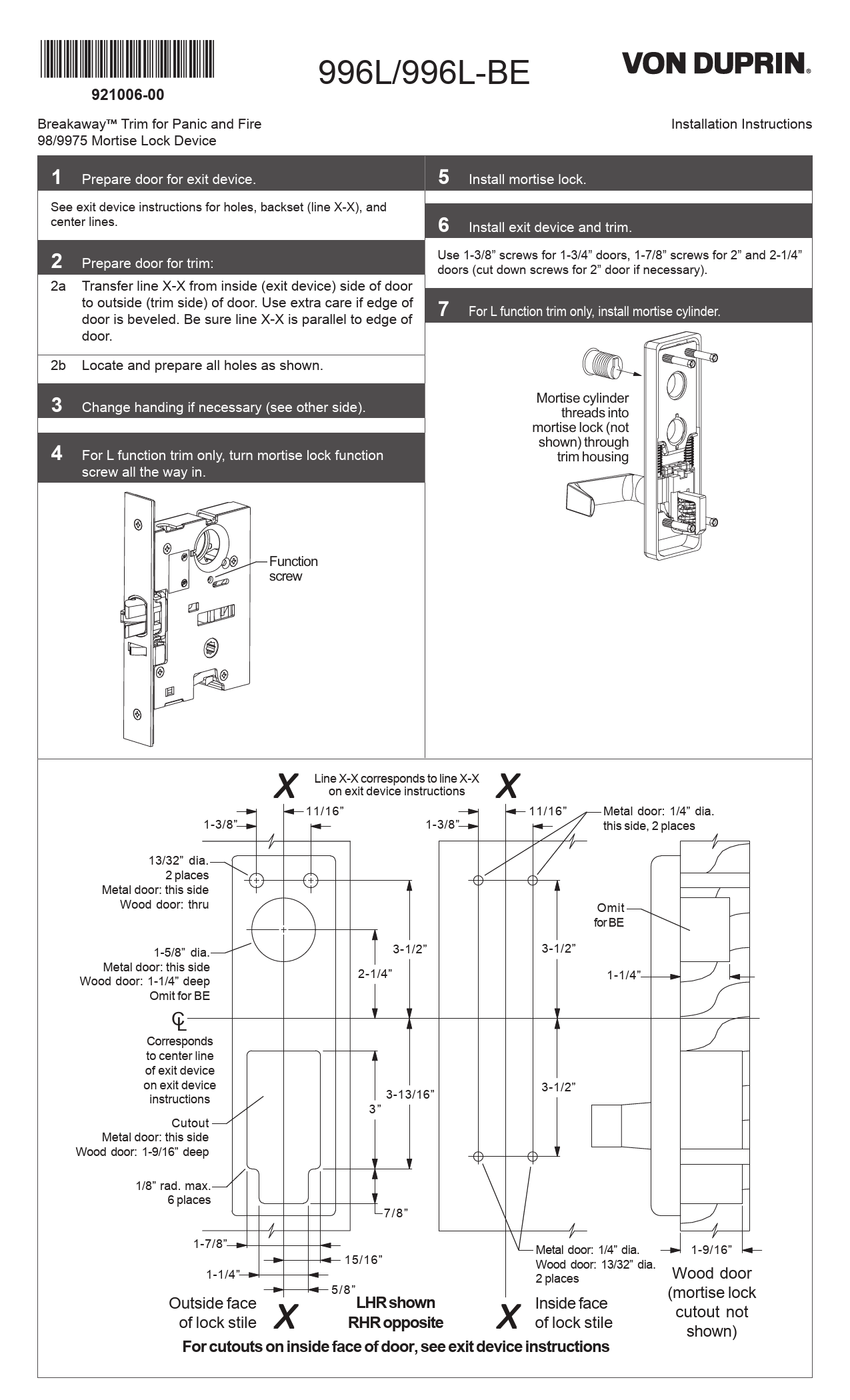
*921006-00*
921006-00
BreakawayTM Trim for Panic and Fire 98/9975 Mortise Lock Device

996L/996L-BE

Installation Instructions

1 Prepare door for exit device.
See exit device instructions for holes, backset (line X-X), and center lines.
2 Prepare door for trim:
2a Transfer line X-X from inside (exit device) side of door to outside (trim side) of door. Use extra care if edge of door is beveled. Be sure line X-X is parallel to edge of door.
2b Locate and prepare all holes as shown.

5 Install mortise lock.
6 Install exit device and trim.
Use 1-3/8" screws for 1-3/4" doors, 1-7/8" screws for 2" and 2-1/4" doors (cut down screws for 2" door if necessary).
7 For L function trim only, install mortise cylinder.

3 Change handing if necessary (see other side). 4 For L function trim only, turn mortise lock function
screw all the way in.

Mortise cylinder threads into
mortise lock (not shown) through
trim housing

Function screw

1-3/8"

X Line X-X corresponds to line X-X on exit device instructions

11/16"

1-3/8"

X
11/16"

Metal door: 1/4" dia. this side, 2 places

13/32" dia. 2 places
Metal door: this side Wood door: thru
1-5/8" dia. Metal door: this side Wood door: 1-1/4" deep
Omit for BE
CL
Corresponds to center line of exit device on exit device instructions
Cutout Metal door: this side Wood door: 1-9/16" deep

3-1/2" 2-1/4"
3-13/16" 3"

Omit for BE 3-1/2"
1-1/4"
3-1/2"

1/8" rad. max. 6 places

7/8"

1-7/8"

Metal door: 1/4" dia.

1-9/16"

1-1/4"

15/16"

Wood door: 13/32" dia. 2 places

Wood door

X Outside face of lock stile

5/8"
LHR shown RHR opposite

X Inside face of lock stile

(mortise lock cutout not shown)

For cutouts on inside face of door, see exit device instructions

Caution
Do not remove springs from slider.

To Change Lever Handing

Note
Lever cannot be broken down unless trim is mounted on door
and device is locked.

6 Remove spacer.

1 Remove four mounting studs.

7 Place lever in RHR or LHR position.

2 Remove endplate from under slider.

RHR

LHR

Slider Endplate
3 Push up on slider and pivot out to remove guide post assembly.

8 Re-install spacer (see Step 6).
9 Re-install shear pin with head pointed down (see Step 5).
10 Pull lever outwards to align shear pin head with spacer.
11 Re-install cam with "L" visible for LHR or "R" visible for RHR (see Step 4), then tighten set screw (see Step 5).

Slider

Caution
In Step 3, make sure to keep loose
components on guide post assembly.

RHR

R

L

LHR

12 Re-install retaining ring (see Step 4).
13 Make sure lever is in horizontal position, then re-install guide post assembly.

4 Use retaining pliers to remove retaining ring. Remove cam.

Slider

5 Use 3/32" hex wrench to loosen set screw. Remove shear pin.

14 Re-install end plate (see Step 2) and four mounting studs (see Step 1).
LL Do not over-tighten studs.

Set screw

Customer Service

1-877-671-7011

www.allegion.com

� Allegion 2014 Printed in U.S.A. 921006-00 Rev. 01/14-b