File info: application/pdf · 16 pages · 2.21MB
Elevate Your Ride - arnottinfo.com
this manual complete the electrical connections. (figure 32) figure 30 figure 31 13. before putting the motorcycle completely back together, it is recommended that you air up the system. spray all the hose connections a…
Elevate Your Ride"
Extracted Text
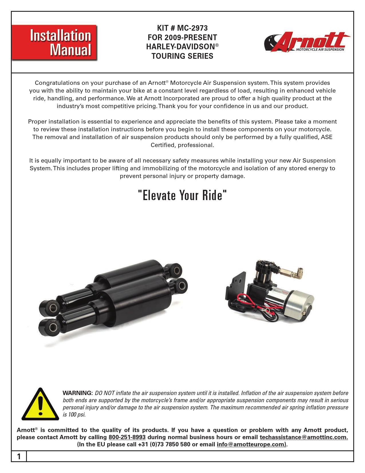
KIT # MC-2973 FOR 2009-PRESENT HARLEY-DAVIDSON� TOURING SERIES
Congratulations on your purchase of an Arnott� Motorcycle Air Suspension system. This system provides you with the ability to maintain your bike at a constant level regardless of load, resulting in enhanced vehicle
ride, handling, and performance. We at Arnott Incorporated are proud to offer a high quality product at the industry's most competitive pricing. Thank you for your confidence in us and our product.
Proper installation is essential to experience and appreciate the benefits of this system. Please take a moment to review these installation instructions before you begin to install these components on your motorcycle. The removal and installation of air suspension products should only be performed by a fully qualified, ASE Certified, professional.
It is equally important to be aware of all necessary safety measures while installing your new Air Suspension System. This includes proper lifting and immobilizing of the motorcycle and isolation of any stored energy to
prevent personal injury or property damage.
"Elevate Your Ride"

WARNING: DO NOT inflate the air suspension system until it is installed. Inflation of the air suspension system before both ends are supported by the motorcycle's frame and/or appropriate suspension components may result in serious personal injury and/or damage to the air suspension system. The maximum recommended air spring inflation pressure is 100 psi.

Arnott� is committed to the quality of its products. If you have a question or problem with any Arnott product, please contact Arnott by calling 800-251-8993 during normal business hours or email techassistance@arnottinc.com.
(In the EU please call +31 (0)73 7850 580 or email info@arnotteurope.com).

1 11-MC-FLT-SR

REV 3

09/27/2018

KIT # MC-2973 FOR 2009-PRESENT HARLEY-DAVIDSON� TOURING SERIES

BILL OF MATERIALS MC-2973 - FLT SUSPENSION SYSTEM, 2009-PRESENT , SMOOTH RIDE

QTY 1 1 1 1 1 1 1 1 1 1 1 1 1 1 1 1 1
QTY 2

20-10550 - INFLATION KIT, 2009-PRESENT, FLT, SMOOTH RIDE

PART NO.

DESCRIPTION

21-9753

FLT PUMP ASSEMBLY

21-9761

90 DEGREE PUSH CONNECT MANIFOLD ASSY

21-3110

MICRO RELAY ASSEMBLY W/ HARNESS

21-7267

1/4" NYLON TUBING ACCESSORY KIT

21-7268

4MM AIRLINE X 6FT. ACCESSORY KIT

21-7269

4MM VOSS AIR FITTING ACCESSORY KIT

21-7271

HARNESS CABLE TIES ACCESSORY KIT

21-7272

SPLIT LOOM- 1 FT LENGTHS ACCESSORY KIT

21-7275

TOGGLE SWITCH ACCESSORY KIT

21-2698

UNIVERSAL FUSE HOLDER ASSEMBLY KIT

21-7262

MANIFOLD BRACKET W/ FASTENER ACCY KIT

21-7282

COMPRESSOR WIRE EXTENSION ACCESSORY KIT

11-MC-FLT-SR

INSTALL MANUAL

20-9983

FLT MOUNTING KIT

20-12358

FLT BAG SPACER KIT

21-7266

BLACK BOLT COVERS ACCESSORY KIT

21-8034

MOTORCYCLE HARDWARE INFLATION ACCY KIT

PART NO. 21-13498

21-13489 - SHOCK KIT
DESCRIPTION SHOCK ASSY, BLACK, SMOOTH RIDE

2 11-MC-FLT-SR

REV 3

09/27/2018

KIT # MC-2973 FOR 2009-PRESENT HARLEY-DAVIDSON� TOURING SERIES
GENERAL INFORMATION:
Reading this manual signifies your agreement to the terms of the general release, waiver of liability, and hold harmless agreement, the full text of which is available at www.arnottcycles.com.
� Avoid damage to air lines and electrical components. � Removal and installation is only to be performed by fully qualified personnel.
CAUTION: Damage to the motorcycle and air suspension system can be incurred if work is carried out in a manner other than specified in the instructions or in a different sequence.
Each owner or installer is unique, therefore installation of this system can be done many different ways. The mounting locations of the compressor and inflation switch are suggestions by our engineers. If proper wiring guidelines and instructions are followed, relocation of the compressor or switch will neither affect the system operation nor void your warranty.
Adjust air shock pressure as required for desired ride quality to maximize the benefits of your system. Excess pressure will result in a firmer ride, too little pressure will allow the suspension to bottom out.
To avoid the possibility of short circuits while working with electric components consult your owner's manual on how to disconnect your battery.

Refer to the Owner's Manual for the bike and instructions for the motorcycle lift for all correct lifting procedures. It is also recommended that you protect any chrome or painted surfaces that may be damaged during lifting, removal or installation process.
SHOCK REMOVAL
Use a solid, level surface to position the bike on a motorcycle lift and use all recommended safety techniques. Lift the bike so the rear wheel is just slightly off the ground.

1.

SUPPORT THE MOTORCYCLE UNDER IT'S FRAME. REMOVE THE SADDLE BAGS, RIGHT SIDE COVER AND SEAT.

(FIGURES 1, 2, 3)

FIGURE 1
3 11-MC-FLT-SR

FIGURE 2
REV 3

09/27/2018

KIT # MC-2973 FOR 2009-PRESENT HARLEY-DAVIDSON� TOURING SERIES

FIGURE 3

2.

REMOVE BOTH OE SHOCKS. (FIGURE 4, 5)

FIGURE 4

FIGURE 5

4 11-MC-FLT-SR

REV 3

09/27/2018

KIT # MC-2973 FOR 2009-PRESENT HARLEY-DAVIDSON� TOURING SERIES

3.

IF THE MOTORCYCLE IS A MODEL YEAR 2009-2013 GO TO STEP #6. FOR A MODEL YEAR 2014-PRESENT REMOVE

THE TWO BOLTS AT THE REAR OF THE RIGHT SADDLE BAG SUPPORT. YOU WILL NEED TO REUSE THE LARGER

BOLT AND NUT ON THE FAR RIGHT OF THE MOTORCYCLE. LOCATE THE INCLUDED 5/16 BOLT & LOCK NUT.

(FIGURES 6, 7, 8)

FIGURE 6

FIGURE 7

FIGURE 8
NOTE: The Arnott accessory kit K-2850 is necessary when installing Arnott Ultimate Ride Kits MC-2904, MC-2905, MC-2906 and
MC-2907 or Smooth Ride Kit 9048 kit for 2014-Present Harley-Davidson� Touring motorcycles equipped with HarleyDavidson's Saddle Bag Guard Rails (P/N 90200561) or 2014-present CVOTM Touring motorcycles with O.E. speakers in the saddle bags. This kit includes CNC Machined aluminum spacers and additional hardware that was designed to securely adjust the placement of the air suspension compressor so that it will not interfere with the Bag Rails or touch the CVO Speaker connection harness. To order this kit call 1-877-900-0247 or visit www.arnottcycles.com

5 11-MC-FLT-SR

REV 3

09/27/2018

KIT # MC-2973 FOR 2009-PRESENT HARLEY-DAVIDSON� TOURING SERIES

4.

MOUNT THE COMPRESSOR TO THE FRAME WITH THE 5/16 BOLT, LOCK NUT, THE LARGER OE BOLT, AND

OE NUT. TIGHTEN BOTH BOLTS. (FIGURE 9, 10, 11, 12)

FIGURE 9 FIGURE 11

FIGURE 10 FIGURE 12

6 11-MC-FLT-SR

REV 3

09/27/2018

KIT # MC-2973 FOR 2009-PRESENT HARLEY-DAVIDSON� TOURING SERIES

5.

CHECK THE CLEARANCE BETWEEN THE COMPRESSOR ASSEMBLY AND THE REAR BRAKE ROTOR.

IF THE CLEARANCE IS LESS THAN �" REMOVE THE COMPRESSOR ASSEMBLY. ADD THE INCLUDED

LOCK WASHER TO THE 5/16 BOLT AND REINSTALL THE COMPRESSOR ASSEMBLY. ADDING THE

LOCK WASHER WILL ONLY BE NECESSARY IN SOME CASES TO INCREASE CLEARANCE BETWEEN

THE COMPRESSOR AND THE BRAKE ROTOR.(FIGURE 13, 14, 15, 16)

FIGURE 13 FIGURE 15
7 11-MC-FLT-SR

FIGURE 14 FIGURE 16

REV 3

09/27/2018

KIT # MC-2973 FOR 2009-PRESENT HARLEY-DAVIDSON� TOURING SERIES

6.

IF THE MOTORCYCLE IS A MODEL YEAR 2014-PRESENT GO TO STEP #8. FOR A MODEL YEAR 2009-2013

YOU WILL NEED TO INSTALL THEN TIGHTEN THE SUPPLIED HEX BOLT AND NON-LOCK NUT ONTO THE

AIR COMPRESSOR BRACKET AS SHOWN BELOW. (FIGURE 17)

FIGURE 17

7.

REMOVE THE FACTORY BAG SUPPORT BOLT ON THE RIGHT SIDE OF THE MOTORCYCLE AND INSTALL

THE PUMP BRACKET BOLT THROUGH THE HOLE. TIGHTEN THE SUPPLIED LOCK NUT ON THE BACK SIDE.

THE PREVIOUSLY INSTALLED HEX NUT ACTS AS A SPACER TO PROPERLY ALIGN THE COMPRESSOR

ASSEMBLY. (FIGURE 18, 19)

FIGURE 18
8 11-MC-FLT-SR

FIGURE 19

REV 3

09/27/2018

KIT # MC-2973 FOR 2009-PRESENT HARLEY-DAVIDSON� TOURING SERIES

8.

ATTACH THE INCLUDED WIRE EXTENSION TO THE COMPRESSOR AND WRAP THE WIRES WITH THE

INCLUDED SPLIT LOOM. INSERT THE INCLUDED �" AIR HOSE INTO THE PUSH-TO-CONNECT FITTING

ON THE COMPRESSOR. ROUTE THE WIRES AND AIR HOSE TOWARD THE RIGHT SIDE BATTERY COVER

ATTACHING THEM TO THE FRAME WITH THE INCLUDED ZIP TIES. (FIGURE 20, 21, 22, 23)

FIGURE 20 FIGURE 22

FIGURE 21 FIGURE 23

9 11-MC-FLT-SR

REV 3

09/27/2018

KIT # MC-2973 FOR 2009-PRESENT HARLEY-DAVIDSON� TOURING SERIES

9.

SCREW A VOSS FITTING INTO ONE OF THE AIR SHOCKS. PULL OUT THE WHITE PLUG AND INSERT THE 4MM

AIR HOSE UNTIL YOU FEEL IT SEAT. UNSCREW THE VOSS FITTING FROM THE SHOCK AND VERIFY THAT THE

KEEPER IS ATTACHED TO THE HOSE. SCREW THE FITTING BACK INTO THE SHOCK AND SNUG TIGHT WITH A

10MM WRENCH. (FIGURE 24, 25, 26)

FIGURE 24

FIGURE 25

FIGURE 26

10 11-MC-FLT-SR

REV 3

09/27/2018

KIT # MC-2973 FOR 2009-PRESENT HARLEY-DAVIDSON� TOURING SERIES
10. APPLY BLUE THREAD LOCK TO THE INCLUDED �" CAP SCREWS. MOUNT THE RIGHT SHOCK TO THE MOTORCYCLE WITH THE VOSS FITTING POINTING TOWARD THEMOTORCYCLE. ROUTE THE AIR LINE TOWARD THE RIGHT-SIDE BATTERY COVER. TRIM THE AIR LINE ANDREPEAT WITH THE LEFT SHOCK. ROUTE THE AIR LINE TO THE RIGHT-SIDE BATTERY COVER. MAKE SURETHE AIR LINE WILL NOT BE PINCHED WHEN THE SEAT IS PLACED BACK ON THE MOTORCYCLE. APPLY SOMESOAPY WATER TO THE O-RINGS INSIDE THE INCLUDED BOLT COVERS AND SLIDE THEM OVER THE HEADSOF THE BOLTS. (FIGURE 27, 28, 29)

FIGURE 27

FIGURE 28

FIGURE 29

11 11-MC-FLT-SR

REV 3

09/27/2018

KIT # MC-2973 FOR 2009-PRESENT HARLEY-DAVIDSON� TOURING SERIES
11. MOUNT THE INCLUDED AIR MANIFOLD UNDER THE RIGHT-SIDE BATTERY COVER. THE IMAGES BELOW SHOW SOME OPTIONS WITH THE INCLUDED MOUNTING HARDWARE. TRIM THE �" COMPRESSOR HOSE AND INSERT IT INTO THE PUSH-TO-CONNECT FITTING ON THE AIR MANIFOLD. SCREW THE 2 VOSS FITTINGS INTO THE MANIFOLD AND FOLLOWING THE SAME PROCEDURE AS IN STEP #9 ATTACH THE 4MM AIR LINES. (FIGURES 30, 31)

FIGURE 30

FIGURE 31

12. LOCATE A SUITABLE MOUNTING LOCATION FOR THE INCLUDED TOGGLE SWITCH. MOUNT IN A LOCATION THAT WILL PROVIDE EASE OF ACCESS. SUCH AS BEHIND OF THE REAR CYLINDER ON THE LEFT SIDE COVER. ROUTE THE SWITCH WIRES TO THE MANIFOLD. USING THE WIRING DIAGRAM IN THE BACK OF THIS MANUAL COMPLETE THE ELECTRICAL CONNECTIONS. (FIGURE 32)

FIGURE 32
13. BEFORE PUTTING THE MOTORCYCLE COMPLETELY BACK TOGETHER, IT IS RECOMMENDED THAT YOU AIR UP THE SYSTEM. SPRAY ALL THE HOSE CONNECTIONS AND FITTINGS WITH SOAPY WATER. IF THERE ARE ANY AIR LEAKS IN THE SYSTEM BUBBLES WILL FORM AT THESE LOCATIONS.

12 11-MC-FLT-SR

REV 3

09/27/2018

KIT # MC-2973 FOR 2009-PRESENT HARLEY-DAVIDSON� TOURING SERIES
14. FOR MODEL YEAR 2014-PRESENT MOTORCYCLES BAG SPACERS MUST BE ADDED TO KEEP THE BAGS FROM TOUCHING THE SHOCKS. INSERT THE INCLUDED QUARTER TURN FASTENER WITH INCLUDED WASHER THROUGH THE GROMMET IN THE BAG. SLIDE INCLUDED SPACER OVER THE FASTENER ON THE OTHER SIDE OF THE BAG. INSTALL THE INCLUDED O-RING INTO THE GROOVE IN THE FASTENER. THE O-RING WILL KEEP THE SPACER FROM FALLING OFF THE FASTENER WHEN THE BAGS ARE REMOVED. (FIGURE 33, 34, 35, 36)

FIGURE 33 FIGURE 35
13 11-MC-FLT-SR

FIGURE 34

FIGURE 36

REV 3

09/27/2018

KIT # MC-2973 FOR 2009-PRESENT HARLEY-DAVIDSON� TOURING SERIES
15. THE QUARTER TURN FASTENERS ARE NOT NEEDED IF THE BAGS ARE HELD IN PLACE WITH SCREW STYLE MOUNTS FROM THE FACTORY. SIMPLY SLIDE THE SPACER OVER THE SCREW AND USE THE O-RING TO KEEP THE SPACER IN PLACE. (FIGURE 37, 38, 39, 40)

FIGURE 37 FIGURE 39

FIGURE 38 FIGURE 40

14 11-MC-FLT-SR

REV 3

09/27/2018

KIT # MC-2973 FOR 2009-PRESENT HARLEY-DAVIDSON� TOURING SERIES
16. THE ORIENTATION OF THE VOSS FILL PORT CAN BE CHANGED IN RELATION TO THE SHOCK MOUNTING EYELETS. UNSCREW AND REMOVE THE SHOCK CAN. SNUG THE LOWER SHOCK EYE IN A VISE. GRASPING THE LOWER PORTION OF THE AIR SPRING AND TWIST IT ON THE SHOCK BODY UNTIL THE DESIRED CLOCKING IS REACHED. FLIP THE SHOCK IN THE VISE. THIS TIME GRIPPING THE OTHER END OF THE AIR SPRING. TWIST TO REALIGN THE SHOCK EYES. (FIGURES 41, 42, 43, 44)

FIGURE 41

FIGURE 42

FIGURE 43

FIGURE 44

The terms Harley-Davidson�, Harley�, H-D�, Buell�, Softail�, Dyna�, V-Rod�, Tri-Glide�, and Sportster� are used for reference only. Arnott Air Suspension products are in no way authorized by nor associated with the Harley-Davidson Motor Company. All references to Harley-Davidson terms and models are for reference and identification purposes only. The use and installation of any Arnott Air Suspension product or kit may adversely affect or void your Harley-Davidson� factory warranty. It is the responsibility of the motorcycle owner to check federal, state and local laws and ordinances before modifying or customizing his or her motorcycle. It is the exclusive and total responsibility of the motorcycle owner to determine the suitability of this product for his or her use. The user shall assume all legal obligations, personal injury risk and all liability duties and risk associated with the use of this product. Arnott Air Suspension products are designed and intended for the experienced on-road motorcyclists only and intended for closed course operation. Arnott Air Suspension products and kits are designed exclusively for OEM manufactured and equipped motorcycles with no modifications. Any installation of aftermarket or customized components may adversely affect the operation and performance of Arnott Air suspension kits and components and may void the manufacturer's warranty.These directions are accurate at time of publication. Arnott Inc. reserves the right to revise specifications without notice.

15 11-MC-FLT-SR

REV 3

09/27/2018

KIT # MC-2973 FOR 2009-PRESENT HARLEY-DAVIDSON� TOURING SERIES

16 11-MC-FLT-SR

REV 3

09/27/2018