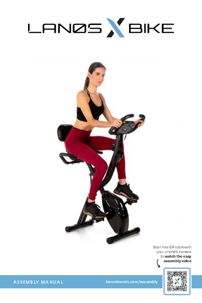
Lanos X-Bike Assembly Manual and User Guide
Welcome
Thank you for choosing the Lanos X-Bike. We take great pride in this quality product and hope it will provide many hours of quality exercise to make you feel better, look better, and enjoy life to its fullest.
It's a proven fact that a regular exercise program can improve your physical and mental health. Too often, our busy lifestyles limit our time and opportunity to exercise. The Lanos X-Bike provides a convenient and simple method to begin your journey of getting your body in shape and achieving a happier and healthier lifestyle.
In the rare instance that a part is missing or defective, please contact Customer Care for assistance. E-mail us at support@lanosbrands.com or submit an inquiry through www.lanosbrands.com. Our knowledgeable Customer Care Staff is available to assist with any questions.
Safety & Health Instructions
- Consult a doctor for your health condition before training to prevent injuries or health issues.
- If on medication that would affect heart rate, blood pressure or cholesterol index, comply with your doctor's instructions before training.
- For heart rate measurement, place both palms on the sensor of the handle bars.
- Inaccurate or excessive training may cause harm to your body and health. Stop training immediately should you experience headache, chest oppression, arrhythmia, abnormally rapid breathing, dizziness or nausea.
- This equipment is for adults only, NOT for children.
- Please place the equipment at a sturdy and level place with added protection from floor damage. For your safety, please keep the space clear within a radius of one meter from the equipment.
- Please make sure all the screws and bolts are tightly screwed before using for the first time.
- For equipment repair and maintenance, please use the Lanos provided spare parts only.
- Wear proper clothes and shoes suitable for fitness training and exercise every time you use the equipment.
- The maximum weight for the equipment is 330 lbs.
- This equipment is not for therapeutic or medical use.
- The equipment is heavy. Use caution when assembling and moving it around to avoid any accident. It is highly recommended that it is assembled and moved by 2 people.
Important Cautions
CAUTION: For consumer use only. Failure to follow all warnings and instructions could result in injury or property damage. Before assembling or using this product, read and follow the Owner's Manual and all other warnings and instructions that accompany this product. Replace this caution label if damaged, illegible, or removed.
Keep others including children & pets away from equipment when in use.
Consult your physician before starting this or any exercise program. This is especially important if you are over the age of 35 or have any pre-existing health condition. Always make sure all nuts and bolts are securely tightened before using this product. This product should not be used by person weighing more than 250 lbs unless otherwise stated in your Owner's Manual.
WARNING: Cancer and Reproductive Harm www.P65Warnings.ca.gov
Consult your physician before starting this or any exercise program. This is especially important if you are over the age of 35, have never exercised before, are pregnant, or suffer from any health problem. This product is for home use only. Do not use in institutional or commercial applications. Failure to follow all warnings and instructions could result in serious injury or death.
WARNING: Exercise can present a health risk. Consult a physician before beginning any exercise program with this equipment. If you feel faint or dizzy, immediately discontinue use of this equipment. Serious bodily injury can occur if this equipment is not assembled and used correctly. Serious bodily injury can also occur if all instructions are not followed. Keep others and pets away from equipment when in use. Always make sure all bolts and nuts are securely tightened prior to each use. Follow all safety instructions in this manual.
Parts & Accessories List
List of Components
- 1 Main Frame
- 2 Front Foot w/ Rollers
- 2a Bolts (2)
- 2b Arch washers (2)
- 2c Cap nuts (2)
- 3 Rear Foot
- 3a Bolts (2)
- 3b Arch washers (2)
- 3c Cap nuts (2)
- 4 Right Pedal
- 5 Left Pedal
- 6 Right Foot Strap
- 7 Left Foot Strap
- 8 Seat Cushion
- 8a Lock nuts (3)
- 8b Flat washers (3)
- 9 Seat Post
- 10 Seat Adjustment Knob*
- 11 Backrest Support
- 11a Carriage bolts (2)
- 11b Flat washers (2)
- 11c Lock nuts (2)
- 11d Semi-round head screws (4)
- 11e Spring washers (4)
- 12 Backrest cushion
- 13 Seat Handles
- 13a Back stator (1)
- 13b Semi-round head screws (2)
- 13c Arch washers (2)
- 13d Lock nuts (2)
- 14 Handlebars w/ Monitor
- 14a Semi-round head screws (4)
- 14b Flat washers (2)
- 14c Arch washers (2)
- 14d AAA Batteries (2)*
- 15 Wrench*
- 16 Allen Key*
*Items marked with an asterisk are located in the styrofoam compartment.
Visual: A diagram displays all parts and hardware, numbered for easy identification during assembly. It also categorizes items as 'Parts', 'Prepositioned Hardware', and 'Tools'.
Assembly Instructions
For a visual guide, scan the QR code or visit lanosbrands.com/assembly.
Step 1: Position the Main Frame
Place the bike's Main Frame (1) into an upright position for easier and safer assembly.
Visual: A person is shown placing the main frame of the exercise bike into an upright position.
Step 2: Adjust the Angle
To adjust the angle, loosen the circular knob on the left side of the Main Frame and pull outward.
Visual: A person is shown loosening a knob on the main frame to adjust its angle.
Step 3: Locate Front Foot
Locate the Front Foot with rollers (2). Remove prepositioned hardware (2a, 2b, 2c).
Visual: The front foot tube with rollers is shown, along with bolts, arch washers, and cap nuts.
Step 4: Attach Front Foot
Align the Front Foot (2) to the Main Frame (1) underneath the flywheel. Rollers must be facing outward from the front of the bike. Align the bolts (2a), arch washers (2b), and cap nuts (2c). Tighten using the provided wrench (15).
Visual: The front foot is being attached to the main frame using bolts, washers, and nuts, with an indication to tighten.
Step 5: Locate Back Foot
Locate the Back Foot (3). Remove prepositioned hardware (3a, 3b, 3c).
Visual: The back foot tube is shown, along with bolts, arch washers, and cap nuts.
Step 6: Attach Back Foot
Align the Back Foot (3) to the Main Frame (1). Align the bolts (3a), arch washers (3b), and cap nuts (3c). Tighten using the provided wrench (15).
Visual: The back foot is being attached to the main frame using bolts, washers, and nuts, with an indication to tighten.
Step 7: Locate Right Pedal
Locate the Right Pedal (4). This is marked 'R'.
Visual: The right pedal is shown, clearly marked with 'R'.
Step 8: Attach Right Pedal
Match the Right Pedal (4) to the Right Crank Arm (R). Screw in a standard clockwise direction by hand to ensure proper alignment between the pedal and crank threading. Then, tighten securely with the provided wrench (15).
Visual: A hand is shown attaching the right pedal to the crank arm, indicating clockwise rotation.
Step 9: Locate Left Pedal
Locate the Left Pedal (5). This is marked 'L'.
Visual: The left pedal is shown, clearly marked with 'L'.
Step 10: Attach Left Pedal
Match the Left Pedal (5) to the Left Crank Arm (L). Screw in a NON-STANDARD COUNTER-CLOCKWISE direction by hand to ensure proper alignment between pedal and crank threading. Then, tighten securely with the provided wrench (15).
Visual: A hand is shown attaching the left pedal to the crank arm, indicating counter-clockwise rotation.
Step 11: Locate Right Foot Strap
Locate the Right Foot Strap (6). This is marked 'R'.
Visual: The right foot strap is shown, marked with 'R'.
Step 12: Fasten Right Foot Strap
With the 'R' marking facing upward, attach the end of the strap with 3 holes to the inside of the pedal. Attach the end of the strap with 4 holes to the outside of the pedal. Adjust to your preference.
Visual: A person is shown attaching the right foot strap to the pedal, aligning holes.
Step 13: Locate Left Foot Strap
Locate the Left Foot Strap (7). This is marked 'L'.
Visual: The left foot strap is shown, marked with 'L'.
Step 14: Fasten Left Foot Strap
With the 'L' marking facing upward, attach the end of the strap with 3 holes to the inside of the pedal. Attach the end of the strap with 4 holes to the outside of the pedal. Adjust to your preference.
Visual: A person is shown attaching the left foot strap to the pedal, aligning holes.
Step 15: Locate Seat Cushion and Seat Post
Locate Seat Cushion (8) and Seat Post (9). Remove prepositioned hardware (8a & 8b).
Visual: The seat cushion and seat post are shown, along with lock nuts and flat washers.
Step 16: Attach Seat Cushion to Seat Post
Align the Seat Cushion (8) with the Seat Post (9). Fasten with washers (8b) and lock nuts (8a), tightening securely using the provided wrench (15).
Visual: A person is shown attaching the seat cushion to the seat post using washers and nuts.
Step 17: Insert Assembled Seat
Insert the assembled seat (Seat Cushion + Seat Post) into the Main Frame (1).
Visual: The assembled seat is being inserted into the main frame of the bike.
Step 18: Secure Seat Height
Find the Seat Adjustment Knob (10) located in the styrofoam compartment of the packaging. Use the knob to secure the seat position on the main frame. The height should be adjusted to your preference after completing assembly.
Visual: A person is shown using the seat adjustment knob to secure the seat.
Step 19: Locate Backrest Support
Locate the Backrest Support (11). Remove prepositioned hardware (11a, 11b, 11c, 11d, 11e).
Visual: The backrest support is shown with various bolts, washers, and nuts.
Step 20: Attach Backrest Support
Align the Backrest Support (11) with the two holes on the Seat Post (9). Use carriage bolts (11a), flat washers (11b), and lock nuts (11c) to secure it, and then tighten with the wrench (15).
Visual: The backrest support is being attached to the seat post using bolts, washers, and nuts.
Step 21: Locate Backrest Cushion
Locate the Backrest Cushion (12) and remaining hardware (11d, 11e).
Visual: The backrest cushion is shown with semi-round head screws and spring washers.
Step 22: Attach Backrest Cushion
Align the Backrest Cushion (12) with the four holes on the Backrest Support (11). Use the semi-round head screws (11d) and spring washers (11e) to secure it, and then tighten with the allen key (16).
Visual: The backrest cushion is being attached to the backrest support using screws and washers.
Step 23: Locate Seat Handles
Locate the Seat Handles (13). Remove prepositioned hardware (13a, 13b, 13c, 13d).
Visual: The seat handles are shown with hardware including a back stator, screws, washers, and nuts.
Step 24: Align Seat Handles
Align Seat Handles (13) with the two holes on the bottom of the Backrest Support (11).
Visual: The seat handles are being aligned with the backrest support.
Step 25: Position Back Stator
Before inserting hardware, place the rounded Back Stator (13a) over the bar so that the holes align.
Visual: The back stator is positioned over the handlebar mounting point.
Step 26: Secure Seat Handles
Secure with semi-round head screws (13b), arch washers (13c), and lock nuts (13d). Tighten using the provided wrench (15) and allen key (16).
Visual: The seat handles are being secured with screws, washers, and nuts.
Step 27: Locate Handlebars w/ Monitor
Locate Handlebars w/ Monitor (14). Remove prepositioned hardware (14a, 14b, 14c).
Visual: The handlebars with the integrated monitor are shown with screws and washers.
Step 28: Insert Handlebars
Insert Handlebars w/ Monitor (14) into the Main Frame (1). First align the holes on the left and right sides, and screw in hardware (14a, 14b, 14c) halfway before tightening completely.
Visual: The handlebars are being inserted into the main frame, with screws partially tightened.
Step 29: Tighten Handlebar Screws
Next, align the holes on the front side. Again, screw in halfway first. Then, using the allen key (16), securely tighten all semi-round head screws on sides and front.
Visual: A person is shown tightening screws on the handlebars using an allen key.
Step 30: Connect Monitor and Insert Batteries
Now, plug it in. Connect the wires between the monitor and frame. Insert provided AAA batteries (14d) into the back of the monitor.
Visual: Wires are being connected between the monitor and frame, and batteries are being inserted into the monitor.
Using Your Lanos X-Bike
Nice work. Now that your exercise bike is fully assembled, the following pages will guide you through further instructions for use and best practices.
If you have any questions or issues with assembly, please contact our Customer Service team at support@lanosbrands.com.
Bike Positions
The Lanos X-Bike can be adjusted to 2 cycling positions or folded up to half its size for storage.
Upright Cycling Position: Allows for a more traditional cycling posture.
Recumbent Cycling Position: Offers a more relaxed posture with back support.
How to Change Cycling Position
- Stand on the side of the bike where the safety knob is located.
- Gently pull the knob and let the rear and front frames open all the way for recumbent cycling position or just half-way for the upright cycling position. Take note of the corresponding holes for the different bike positions.
- Align the knob to the corresponding hole where the screw will automatically lock into place.
- Always make sure that the safety lock is secured in place before getting on the bike.
Dimensions: Recumbent: 32" L x 19.5" W x 41" H; Upright: 26.4" L x 19.5" W x 46" H
Storage Position
- Gently pull the safety knob.
- "Fold" the bike by carefully pushing the rear and front frames together.
- Align the knob to the corresponding hole where the screw will automatically lock into place.
- Use built-in wheels to move the bike into a storage area.
Dimensions: Storage: 19.5" L x 19.5" W x 54.3" H
Visual: An image shows the bike in a storage position.
How the LCD Monitor Works
Specifications
| Function | Range/Unit |
|---|---|
| TIME | 0:00-99:59 MIN/SEC |
| SPEED | 0:00-999.9 MPH |
| DISTANCE | 0:00-999.9 MILES |
| CALORIES | 0:00-999.9 KCAL |
| PULSE | 40-240 BEATS/MIN |
Visual: A close-up image of the Lanos X-Bike's LCD monitor displaying various workout metrics.
Functions
- POWER ON/OFF: Press the button once or start to pedal to power on. The power will automatically shut off after 4 minutes of inactivity.
- SCAN: Press the button until the screen displays SCAN. The computer will automatically scan each function: SPEED, TIME, DISTANCE, CALORIES and PULSE RATE, every 6 seconds. Press the button once to stay in a particular function. Press the button again once to move to the next function.
- TIME: Workout time is displayed in minutes and seconds. The computer automatically counts from 0:00 to 99:59.
- SPEED: Workout speed is displayed in miles per hour.
- DISTANCE: Accumulated distance traveled with every use is displayed to a maximum of 999.9 miles.
- CALORIE: Calorie Readout is an estimate for an average user. It should be used only as a comparison between workouts in this unit.
- PULSE: Pulse readouts are more precise when two hands are on the handlebar grip sensors.
- RESET: Press and hold the button for more than 2 seconds to reset all values to zero.
Workout Guidance
Warm Up Before Your Workout
Stretching before a workout can help with blood circulation and reduce chances of muscle spasms. Please follow the instructions below for warm-up before you start training. Each move should last for at least 30 seconds. Alternate sides. Do NOT stretch fiercely to avoid muscle injury.
Visual: A series of six images demonstrating various stretching exercises for a warm-up routine.
Training Phase
This is for formal exercise, which can improve leg muscle flexibility. Please adjust the training level according to your body and health condition, and choose training intensity that is most suitable for you.
Visual: A graph titled "Heart Rate" shows the relationship between Age (X-axis, 20-75) and Heart Rate (Y-axis, 80-200). It illustrates "Maximum" heart rate, a "Target Zone" (70% and 85%), and "Cool Down" levels. Users should aim to stay within the target zone for at least 12 minutes, with some training for 15-20 minutes.
90 Day Limited Warranty
This Lanos product is warranted to the original purchaser to be free from defects in material or workmanship for a period of one hundred eighty days from the date of the original retail purchase.
This warranty does not cover defects or damage due to improper installation, alteration, accident, or any other event beyond the control of the manufacturer. Defects or damage resulting from misuse, abuse, or negligence will void this warranty. This warranty does not cover scratching or damage that may result from normal usage.
This product is not intended for institutional or commercial use; Lanos does not assume any liability for such use. Institutional or commercial use will void this warranty.
This warranty is nontransferable and is expressly limited to the repair or replacement of the defective product. During the warranty period, Lanos shall repair or replace defective parts at no cost to the purchaser. Shipping charges and insurance are not covered and are the responsibility of the purchaser. Labor charges and related expenses for removal, installation, or replacement of the product or components are not covered under this warranty.
Lanos reserves the right to make substitutions to warranty claims if parts are unavailable or obsolete.
Lanos shall not be liable for loss of use of the product or other consequential or incidental costs, expenses, or damages incurred by the consumer or any other use. The user assumes all risk of injury resulting from the use of this product.
This warranty is expressly in lieu of all other warranties, expressed or implied, including warranties of merchantability or fitness for use to the extent permitted by Federal or State law. Neither Lanos nor any of its representatives assumes any other liability in connection with this product.
All warranty claims must be made through the retailer where the product was originally purchased. A purchase receipt or other proof of date of purchase will be required to process all warranty claims. The model number and part numbers found within the assembly instructions will be required when submitting any parts requests or warranty claims.
For further warranty information or inquiries, please email support@lanosbrands.com.
Visual: An image shows a person using the Lanos X-Bike, with the warranty information presented alongside.
