I175E-EN-02 Q2A Datasheet
File info: application/pdf · 30 pages · 8.69MB
I175E-EN-02 Q2A Datasheet
Q2A - Omron
2 Frequency inverters Type designation 200 V class Specifications Q2A-A Duty rating 2004 2006 2010 2012 2021 2030 2042 2056 2070 Max. applicable motor output (kW)
Full PDF Document

If the inline viewer fails, it will open the original document in compatibility mode automatically. You can also open the file directly.
Extracted Text
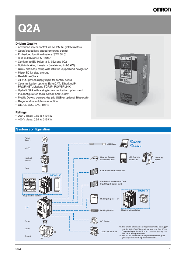
Q2A

Driving Quality � Advanced motor control for IM, PM & SynRM motors � Open/closed loop speed or torque control � Embedded functional safety (STO SIL3) � Built-in C3 class EMC filter � Conform to EN 60721-3-3, 3S2 and 3C2 � Built-in braking transistor (models up to 90 kW) � Quick and easy setup with intuitive keypad and navigation � Micro SD for data storage � Real-Time Clock � 24 VDC power supply input for control board � Communication options: EtherCAT, EtherNet/IP,
PROFINET, Modbus TCP/IP, POWERLINK � Up to 5 Q2A with a single communication option card � PC configuration tools: Q2edit and Q2dev � Mobile Device connectivity (via USB or optional Bluetooth) � Regenerative solutions as option � CE, UL, cUL, EAC, RoHS
Ratings � 200 V class: 0.55 to 110 kW � 400 V class: 0.55 to 315 kW
System configuration
Power Supply
MCCB

Input AC Reactor
Filter

D1000 kit*1

Regenerative solution Q2A
Choke Motor Ground
Q2A

USB Cable

Remote Operator Extansion Cable

LCD Remote Installation

Mounting Bracket

Communication Option Card

Feedback Speed Option Card Input/Output Option Card
Braking chopper or

R1000 kit*2

Braking Resistor

Regenerative solution

DC Reactor

Output AC Reactor

*1. The D1000 kit includes a Regenerative DC bus supply unit (D1000), EMC filter and low harmonic filter. If the D1000 kit is purchased, it is not necessary to buy the EMC filter as separate item.
*2. The R1000 kit includes a Regenerative braking unit (R1000) and current suppression reactor.

1

Specifications
Type designation

Q2A-A4002-AAA

Q2 series
A series
IP20 protection class
Voltage: 2: Three-phase 200 VAC 4: Three-phase 400 VAC

Version
Standard Coating specifications
Standard specifications
Rated Output Current Normal Duty 002: 2.1 [A]
~ 675: 675 [A]

200 V class

Power supply

Output characteristics

Q2A-A
Max. applicable motor output (kW)
Inverter capacity (kVA)
Rated output current (A) Overload tolerance*5 Carrier frequency*6 (without derating the drive capacity) Max. output voltage
Max. output frequency
Rated voltage and frequency Allowable voltage fluctuation Allowable frequency fluctuation Input Power (kVA) Weight (kg)

Duty rating HD*1 ND*2 HD*3 ND*4 HD ND
HD ND

2004

2006

2010

2012

2021

0.55

0.75

1.5

2.2

4.0

0.75

1.1

2.2

3.0

5.5

1.2

1.9

3.0

4.2

6.7

1.3

2.3

3.7

4.6

8.0

3.2

5.0

8.0

11

17.5

3.5

6.0

9.6

12.2

21

� HD: 150% of the rated output current for 60 seconds � ND: 110% of the rated output current for 60 seconds

� HD: 8 kHz � ND: 2 kHz

� Proportional to input voltage: 200-240 V

� AOLV, EZOLV: 120 Hz � CL-V/f, CLV, AOLV/PM, CLV/PM: 400 Hz � V/f, OLV, OLV/PM: 590 Hz

� 3-phase AC power supply 200-240 V at 50/60 Hz � DC power supply 270-340 VDC

�15% to +10%

�5%

1.5

2.0

3.7

5.3

8.6

2.0

2.8

5.3

7.1

12.5

3.5

3.9

2030 5.5 7.5 9.5 11.4 25 30
12.5 16.8 4.2

2042 7.5 11 12.6 16 33 42
16.8 21.6

2056 11 15 17.9 21.3 47 56
24.2 32.6 6

2070 15 18.5 22.9 26.7 60 70
32.6 39.9 8.5

2

Frequency inverters

Output characteristics

Q2A-A Max. applicable motor output (kW)
Inverter capacity (kVA) Rated output current (A)

Duty rating HD*1 ND*2 HD*3 ND*4
HD
ND

Overload tolerance*5

Carrier frequency*6 (without derating the drive capacity)
Max. output voltage

Max. output frequency

Power supply

Rated voltage and frequency

Allowable voltage fluctuation

Allowable frequency fluctuation

Input Power (kVA)

HD

ND

Weight (kg)

2082

2110

2138

2169

2211

18.5

22

30

37

45

22

30

37

45

55

28.6

33.5

43.8

55.3

68.6

31.2

41.9

52.6

64.4

80.4

75

88

115

145

180

82

110

138

169

211

� HD: 150% of the rated output current for 60 seconds

� ND: 110% of the rated output current for 60 seconds

� HD: 8 kHz � ND: 2 kHz

� HD: 5 kHz � ND: 2 kHz

� Proportional to input voltage: 200-240 V

� AOLV, EZOLV: 120 Hz � CL-V/f, CLV, AOLV/PM, CLV/PM: 400 Hz � V/f, OLV, OLV/PM: 590 Hz

� 3-phase AC power supply 200-240 V at 50/60 Hz � DC power supply 270-340 VDC

�15% to +10%

�5%

39.9

34.1

46.1

56.5

68.2

47.4

46.1

56.5

68.2

83.1

9.0

22

24

39

40

2257 55 75 81.9 97.9 215 257
83.1 113 67

2313 75 90 108 119 283 313
113 135

2360 90 110 132 137 346 360
135 164 104

2415 110 � 158 � 415 �
164 � 119

*1. The maximum applicable motor output complies with 208 V motor ratings as specified in NEC Table 430.250. The rated output current of the drive output amps must be equal to or more than the motor rated current.
*2. The maximum applicable motor output is based on 4-pole, general-purpose 220 V motor ratings. The rated output current of the drive output amps must be equal to or more than the motor rated current.
*3. The rated output capacity is calculated with a rated output voltage of 208 V. *4. The rated output capacity is calculated with a rated output voltage of 220 V. *5. Derating may be necessary for applications that start and stop frequently. *6. Derate the drive capacity to use values to 15 kHz maximum (2004 to 2138 models) or 10 kHz maximum (2169 to 2415 models).

400 V class

Q2A-A Max. applicable motor output (kW)
Inverter capacity (kVA)
Rated output current (A)

Input voltage < 460 V*1  460 V*2 < 460 V*3  460 V*4
< 460 V
 460 V

Duty rating HD ND HD ND HD ND HD ND HD ND HD ND

Output characteristics

Overload tolerance*5

Carrier frequency*6 (without derating the drive capacity)
Max. output voltage

Max. output frequency

Rated voltage and frequency

Power supply

Allowable voltage fluctuation

Allowable frequency fluctuation

Input Power (kVA)

< 460 V HD ND

 460 V

HD ND

Weight (kg)

4002 4004 4005 4007 4009 4012 4018

0.55 0.75 1.5 2.2 3.0 3.7 5.5

0.75 1.5 2.2 3.0 3.7 5.5 7.5

0.55 0.75 1.5 2.2 3.0 3.7 5.5

0.75 1.5 2.2 3.0 3.7 5.5 7.5

1.2 2.2 3.2 3.6 4.7 6.1 10

1.4 2.7 3.6 4.7 5.9 7.8 12

1.3 1.7 2.7 3.8 5.5 6.1 8.8

1.7 2.4 3.8 5.5 6.1 8.8 11

1.8 3.4 4.8 5.5 7.2 9.2 14.8

2.1 4.1 5.4 7.1 8.9 11.9 17.5

1.6 2.1 3.4 4.8 6.9 7.6 11

2.1 3.0 4.8 6.9 7.6 11

14

� HD: 150% of the rated output current for 60 seconds � ND: 110% of the rated output current for 60 seconds

� HD: 8 kHz � ND: 2 kHz

� Proportional to input voltage: 380-480 V

� AOLV, EZOLV: 120 Hz � CL-V/f, CLV, AOLV/PM, CLV/PM: 400 Hz � V/f, OLV, OLV/PM: 590 Hz

� 3-phase AC power supply 380-480 V at 50/60 Hz � DC power supply 513-679 VDC

-15% to +10%

�5%

1.5 2.8 3.7 5.3 7.1 9.3 13

2.0 3.7 5.3 7.1 9.3 13

17

1.3 1.7 3.2 4.6 6.1 7.5 11

2.1 4.0 5.6 7.5 9.1 13

18

3.5

3.9

4.2

4023 7.5 11 7.5 11 12 15 11 17 18 23.4 14 21
17 24 15 26

4031 11 15 11 15 16 20 17 22 24 31 21 27
24 33 21 35 6.0

4038 15 18.5 15 18.5 20 25 22 27 31 38 27 34
33 40 28 42

4044 18.5 22 18.5 22 26 29 27 32 39 44 34 40
40 48 35 50 7.5

4060 22 30 22 30 30 39 32 41 45 59.6 40 52
34 46 30 49 12

4075 30 37 30 37 39 49 41 52 60 74.9 52 65
46 57 40 60 17

Q2A

3

Q2A-A Max. applicable motor output (kW)
Inverter capacity (kVA)
Rated output current (A)

Input voltage < 460 V*1  460 V*2 < 460 V*3  460 V*4
< 460 V
 460 V

Duty rating HD ND HD ND HD ND HD ND HD ND HD ND

Output characteristics

Overload tolerance*5

Carrier frequency*6 (without derating the drive capacity)
Max. output voltage

Max. output frequency

Rated voltage and frequency

Power supply

Allowable voltage fluctuation

Allowable frequency fluctuation

Input Power (kVA)

HD < 460 V
ND

 460 V

HD ND

Weight (kg)

4089 4103 4140 4168 4208 4250 4296

37

45

55

75

90

110 132

45

55

75

90

110 132 160

37

45

55

75

90

110 150

45

55

75

90

110 150 185

49

60

74

99

118 142 171

59

68

92

111 137 165 195

52

61

76

99

124 143 191

61

76

99

124 143 191 241

75

91

112 150 180 216 260

89.2 103 140 168 208 250 296

65

77

96

124 156 180 240

77

96

124 156 180 240 302

� HD: 150% of the rated output current for 60 seconds � ND: 110% of the rated output current for 60 seconds

� HD: 8 kHz � ND: 2 kHz

� HD: 5 kHz � ND: 2 kHz

� Proportional to input voltage: 380-480 V

� AOLV, EZOLV: 120 Hz � CL-V/f, CLV, AOLV/PM, CLV/PM: 400 Hz � V/f, OLV, OLV/PM: 590 Hz

� 3-phase AC power supply 380-480 V at 50/60 Hz � DC power supply 513-679 VDC

-15% to +10%

�5%

57

69

84

113 136 165 198

69

84

113 136 165 198 239

49

59

72

98

117 142 193

73

88

120 143 174 236 295

22

25

38

39

71

4371 160 200 185 220 200 244 241 288 304 371 302 361
239 297 240 352 122

4389 200 220 220 260 244 256 288 330 371 389 361 414
297 327 288 410 126

4453
220 250 260 300 272 298 330 380 414 453 414 477

4568
250 315 300 335 298 374 380 410 453 568 477 515

� HD: 2 kHz � ND: 2 kHz

327 370 370 465 335 382 468 526 198

4675 315 355 335 370 398 444 410 482 605 675 515 605
465 523 429 584 207

*1. The maximum applicable motor output complies with 380 V motor ratings as specified in Annex G of IEC 60947-4-1. The rated output current of the drive output amps must be equal to or more than the motor rated current.
*2. The maximum applicable motor output complies with 460 V motor ratings as specified in NEC Table 430.250. The rated output current of the drive output amps must be equal to or more than the motor rated current.
*3. The rated output capacity is calculated with a rated output voltage of 380 V. *4. The rated output capacity is calculated with a rated output voltage of 460 V. *5. Derating may be necessary for applications that start and stop frequently. *6. Derate the drive capacity to use values to 15 kHz maximum (4002 to 4103 models), 10 kHz maximum (4140 to 4389 models) or 5 kHz maximum (4453
to 4675 models).

Control functions

Common specifications
Model number Q2A-A
Control methods
Frequency control range Frequency tolerance Frequency setting resolution Output frequency resolution Frequency setting signal
Starting torque*1
Speed control range
Zero speed control Torque limits Accel/Decel Time

Specifications
V/f Control (V/f), Closed Loop V/f Control (CL-V/f), Open Loop Vector Control (OLV), Closed Loop Vector Control (CLV), Advanced Open Loop Vector Control (AOLV), Open Loop Vector Control for PM (OLV/PM), Advanced Open Loop Vector Control for PM (AOLV/PM), Closed Loop Vector Control for PM (CLV/PM), EZ Open Loop Vector Control (EZOLV)
� AOLV, EZOLV: 0.01 to 120 Hz � CL-V/f, CLV, AOLV/PM, CLV/PM: 0.01 to 400 Hz � V/f, OLV, OLV/PM: 0.01 to 590 Hz
� Digital inputs: �0.01% of the max. output frequency (-10 to +40 �C) � Analog inputs: �0.1% of the max. output frequency (25 �10 �C)
� Digital inputs: 0.01 Hz � Analog inputs: 1/2048 of the max. output frequency (11-bit signed)
0.001 Hz � Main speed freq reference: -10 to +10 VDC (20 k), 0 to 10 VDC (20 k), 4 to 20 mA (250 ), 0 to 20 mA (250 ) � Main speed reference: Pulse train input (max. 32 kHz)
� V/f, CL-V/f: 150%/3Hz � OLV, AOLV: 200%/0.3Hz � CLV, AOLV/PM, CLV/PM: 200%/0 rpm (rev/min) � OLV/PM: 100%/5% speed � EZOLV: 100%/1% speed
� V/f, CL-V/f: 1:40 � OLV, AOLV: 1:200 � CLV, CLV/PM: 1:1500 � OLV/PM: 1:20 � AOLV/PM: 1:100 (when high frequency injection is enabled) � EZOLV: 1:100
Possible in these control methods: CLV, AOLV/PM, CLV/PM
Parameter settings allow different limits in four quadrants in these control methods: OLV, CLV, AOLV, AOLV/PM, CLV/ PM, EZOLV
0.0 to 6000.0 s (the drive can set four pairs of different acceleration and deceleration times)

4

Frequency inverters

Environment

Protection functions

Functionality

Control functions

Braking torque
V/f characteristics
Main control functions
Motor Momentary overcurrent Overload Overvoltage Undervoltage
Momentary power loss ride-thru
Heatsink overheat Stall prevention Ground fault DC Bus charge LED Area of use Power supply Ambient temperature Humidity Storage temperature
Surrounding area
Altitude Vibration Installation orientation Safety standard Protection design*4

Approximately 20% Approximately 125% with a dynamic braking option Short-time average deceleration torque: � Motor output 0.4/0.75 kW: over 100% � Motor output 1.5 kW: over 50% � Motor output 2.2 kW or higher: over 20%, over-excitation braking/high slip braking allow for approximately 40% Continuous regenerative torque: approx. 20%, dynamic braking option allows for approximately 125%, 10% ED, 10 s*2 Models 2004 to 2138 and 4002 to 4168 have a built-in braking transistor. Short-time average deceleration torque refers to the torque needed to decelerate the motor (uncoupled from the load) from the rated speed to zero. Motor characteristics can change the actual specifications. Motor characteristics change the continuous regenerative torque and short-time average deceleration torque for motors of 2.2 kW or higher.
Select from 15 pre-defined V/f patterns or a user-set V/f pattern
Torque control, Droop control, Speed/Torque control switching, Feed forward control, Zero servo function, Restart after momentary power loss, Speed search, Overtorque/Undertorque detection, Torque limit, 17 step speed (max), Accel/Decel switch, S-curve acceleration/deceleration, 3-wire sequence, Auto-tuning (rotational and stationary), Dwell function, Cooling fan ON/OFF, Slip compensation, Torque compensation, Frequency Jump, Upper/lower limits for frequency reference, DC injection braking at start and stop, Overexcitation braking, High slip braking, PID control (with sleep function), Energy saving control, MEMOBUS/Modbus communication (RS-485 max. 115.2 kbps), Auto restart, Application presets, Q2dev (customized functions), Removable terminal block with parameter backup function, Online tuning, KEB, Overexcitation deceleration, Inertia (ASR) tuning, Overvoltage suppression, High frequency injection
Electronic thermal overload protection
Drive stops when the output current exceeds 200% of the HD output current
Drive stops when the output current exceeds 150% of the HD output current or 110% of the ND output current for 60 seconds*3
200 V class: Stops when the DC bus voltage is more than approximately 410 V 400 V class: Stops when the DC bus voltage is more than approximately 820 V
200 V class: Stops when the DC bus voltage decreases to less than approximately 190 V 400 V class: Stops when the DC bus voltage decreases to less than approximately 380 V
Stops when power loss is longer than 15 ms. Continues operation if power loss is shorter than 2 s (depending on parameter settings). Stop time may be shortened depending on the load and motor speed. Drive capacity will change the continuous operation time. A momentary power loss recovery unit is necessary to continue operation through a 2 s power loss on models 2004 to 2056 and 4002 to 4031.
Protected by thermistor
Stall prevention is available during acceleration, deceleration and during run
Electronic circuit protection This protection detects ground faults during run. The drive will not provide protection when there is a low-resistance ground fault for the motor cable or terminal block or energizing the drive when there is a ground fault.
Charge LED illuminates when DC bus voltage is more than 50 V.
Indoor (no corrosive gas, dust, etc...)
Overvoltage Category III
-10�C to +50�C
95% RH or less (without condensation)
-20�C to +70�C (short-term temperature during transportation)
Pollution degree 2 or less Install the drive in an area without: � Oil mist, corrosive or flammable gas or dust � Metal powder, oil, water or other unwanted materials � Radioactive materials or flammable materials, including wood � Harmful gas or fluids � Salt � Direct sunlight
Up to 1000 meters max. (output derating of 1% per 100 m above 1000 m, max. 3000 m)
� 10 Hz to 20 Hz: 1G (9.8 m/s�) � 20 Hz to 55 Hz: 2004 to 2211 and 4002 to 4168 - 0.6G (5.9 m/s�) / 2257 to 2415 and 4208 to 4675 - 0.2G (2 m/s�)
Install the drive vertically for sufficient airflow to cool the drive.
� UL61800-5-1 � EN61800-3 � IEC/EN61800-5-1 � Two Safe Disable inputs and one EDM output according to ISO/EN13849-1 Cat.III PLe, IEC/EN61508 SIL3
Open chassis type: IP20

*1. Correctly select drive capacity for this starting torque in these control methods: OLV, CLV, AOLV, AOLV/PM, CLV/PM. *2. Set L3-04 to 0 (Stall Prevention during Decel = Disabled) when operating the drive with a regenerative converter, regenerative unit, braking unit, braking
resistor or braking resistor unit. Failure to obey could prevent the drive from stopping in the specified deceleration time and cause serious injury or death. *3. The drive can trigger the overload protection function within the overload tolerance if the output frequency is less than 6 Hz. Do not allow the overload
more than once every ten minutes. *4. Install an UL Type 1 kit on an Open-chassis type (IP20) to convert the drive to a Enclosed wall-mounted type (UL Type 1).

Q2A

5

Dimensions
Q2A inverter

Figure 1 Figure 4

Figure 2 Figure 5

Figure 3 Figure 6

Figure 7

Figure 8

Figure 9

Voltage

Inverter model Q2A-A

Dimensions (mm)

Fig.

W W1 W2 W5

H

H1 H2 H3 H4

D

D1 D2 t1 t2 d

200 V

2004, 2006, 2010, 2012

1 140 102 102

�

260 248

6

�

�

176 138 38 1.6 5 M5

2021, 2030, 2042

211

73

2056

2 180 140 140

300 284

8

202 134 68

1.6

2070, 2082

3 220 192 192

350 335

227 140 87 2.3 2.3 M6

2110

4 240 195 186 12 400 375 17.5

17.5 280 166 114

2138

5 255 170 165

450 424 16

29

21

2169, 2211

6 264 190 182

543 516 17.5 28.5 20.5 335 186 149

M8

2257, 2313

7 312 218 218 18 700 659 28 43.5 28.5 420 260 160 4.5 4.5 M10

2360, 2415

8 440 370 370 20 800 757

44

30 472 254 218

M12

400 V

4002, 4004, 4005

1 140 102 102

�

260 248

6

�

�

176 138 38 1.6 5 M5

4007, 4009, 4012, 4018, 4023

211

73

4031, 4038

2 180 140 140

300 284

8

202 134 68

1.6

4044

3 220 192 192

350 335

227 140 87 2.3 2.3 M6

4060

246

106

4075

4 240 195 186 12 400 375 17.5

17.5 280 166 114

4089, 4103

5 255 170 165

450 424 16

29

21

4140, 4168

6 264 190 182

543 516 17.5 28.5 20.5 335 186 149

M8

4208, 4250, 4296

7 312 218 218 18 700 659 28 43.5 28.5 420 260 160 4.5 4.5 M10

4371, 4389

8 440 370 370 20 800 757

44

30 472 254 218

M12

4453, 4568, 4675

9 510 450 450

1140 1093 25.5 43.5 30.5 480 260 220

6

Frequency inverters

Line filters

W

H

B

L

A

M (4x)

Figure 1 (Footprint type)

Voltage

Reference

Fig. W

200 V/400 V

Q2-FIA4010-SE

1

140

Q2-FIA4020-SE

Q2-FIA4035-SE

Q2-FIA4050-SE

178

Q2-FIA4080-SE

2

80

Q2-FIA4100-SE

90

Q2-FIA4170-SE

120

Q2-FIA4410-SE

3

260

Q2-FIA4600-SE

Input AC Reactor

L
A
Figure 2 (Book type)
H 52
56 205 150 170 115 135

H
B W

H

40

L

35 BW

Dimensions (mm)

L

A

306

290

343

323

250

270

330

255

452

365

306

2 x 120

A

A

Figure 3 (Busbar termination type)

B

M

102

M5

140

�

M6

65

M10

102

235

M12

Weight (kg)
1.1 1.4 1.8 2.5 4.3 4.0 6.0 9.5 11.0

Voltage

Reference

Dimensions (mm)

Weight

A

B1

B2

C1

C2

D

E

F

(kg)

200 V

AX-RAI02800100-DE

120

�

70

�

120

80

52

5.5

1.78

AX-RAI00880200-DE

80

62

2.35

AX-RAI00350335-DE

180

85

190

140

55

6

5.5

AX-RAI00180670-DE

AX-RAI00091000-DE

205

6.5

AX-RAI00071550-DE

105

85

11.7

AX-RAI00042300-DE

120

-

150

�

400 V

AX-RAI07700042-DE

120

�

70

�

120

80

52

5.5

1.78

AX-RAI07700050-DE

AX-RAI03500090-DE

80

62

2.35

AX-RAI03500100-DE

AX-RAI01300170-DE

180

75

195

140

55

6

5.5

AX-RAI00740335-DE

85

190

AX-RAI00360500-DE

205

6.5

AX-RAI00290780-DE

105

75

11.2

AX-RAI00191150-DE

240

110

275

200

16.0

AX-RAI00111850-DE

AX-RAI00072700-DE

180

�

210

�

110

25.4

AX-RAI00043350-DE

140

85

18.6

AX-RAI00034500-DE

165

110

27.0

AX-RAI00025350-DE

300

170

260

105

33.5

Q2A

7

DC Reactor
B

C

F

D

E

A

Voltage 200 V
400 V

Reference
AX-RC06750061-DE AX-RC03510093-DE AX-RC02510138-DE AX-RC01600223-DE AX-RC01110309-DE AX-RC00840437-DE AX-RC00590614-DE AX-RC00440859-DE AX-RC00301275-DE AX-RC43000020-DE AX-RC10100069-DE AX-RC06400116-DE AX-RC04410167-DE AX-RC03350219-DE AX-RC02330307-DE AX-RC01750430-DE

Figure 1

Figure 2

Fig

Dimensions (mm)

Weight

A

B

C

D

E

F

G

H

(kg)

1

84

113

105

101

66

5

7.5

2

1.60

116

1.95

108

135

124

120

82

6.5

9.5

9.5

3.20

120

152

136

135

94

7

�

5.20

146

6.00

150

177

160

160

115

2

11.4

183

14.3

2

195

161

163

185

88

10

�

17.0

1

84

113

96

101

66

5

7.5

2

1.22

116

1.95

108

135

133

120

82

6.5

9.5

9.5

3.70

120

152

136

135

94

7

-

5.20

146

6.00

150

177

160

160

115

2

11.4

183

14.3

8

Frequency inverters

Output AC Reactor

Voltage

Reference

Dimensions (mm)

Weight

A

B1

B2

C1

C2

D

E

F

(kg)

200 V

AX-RAO07600042-DE

120

�

70

�

120

80

52

5.5

1.78

AX-RAO04100075-DE

80

62

2.35

AX-RAO03000105-DE

AX-RAO01830160-DE

180

85

195

140

55

6

5.5

AX-RAO01150220-DE

AX-RAO00950320-DE

210

6.5

AX-RAO00630430-DE

95

65

9.1

AX-RAO00490640-DE

105

75

11.7

AX-RAO00390800-DE

240

110

275

200

16.0

AX-RAO00330950-DE

AX-RAO00251210-DE

300

AX-RAO00191450-DE

130

�

215

�

85

18.6

AX-RAO00161820-DE

160

110

27.0

AX-RAO00132200-DE

300

165

300

125

33.5

400 V

AX-RAO16300038-DE

120

�

80

�

120

80

62

5.5

2.35

AX-RAO11800053-DE

AX-RAO07300080-DE

180

85

195

140

55

6

5.5

AX-RAO04600110-DE

AX-RAO03600160-DE

210

6.5

AX-RAO02500220-DE

95

65

9.1

AX-RAO02000320-DE

240

110

275

200

75

16.0

AX-RAO01650400-DE

AX-RAO01300480-DE

AX-RAO00800750-DE

120

281

85

18.6

AX-RAO00680900-DE

150

110

27.0

AX-RAO00531100-DE

300

125

350

105

27.9

AX-RAO00401490-DE

170

�

270

-

125

44.0

AX-RAO00331760-DE

AX-RAO00262170-DE

360

230

315

300

150

8

55.0

AX-RAO00212600-DE

420

240

370

75.0

AX-RAO00173250-DE

480

275

400

370

165

10

136.0

AX-RAO00134440-DE

305

400

195

165.0

AX-RAO00115250-DE

335

225

215.0

Q2A

9

Chokes
D

D C

D

C

C

G
E A
Figure 1 Reference AX-FER2102-PE AX-FER2815-PE AX-FER5045-PE AX-FER5255-PE
LCD keypad

F B
F

G
E A

FB

H

G

I

FB

E A

Figure 2

Figure 3

Dimensions (mm)

Fig

D (diameter) Motor (kW)

Weight (kg)

A B C D E F G (diameter) H I

1

21

< 2.2

86 24 50 21 70 12

4

��

0.09

28

< 15

106 25 65 28 90 12.5

0.22

2

50

< 45

150 51 112 50 125 30

5

0.53

3

52

 55

47 75.5 110 52 30 58.5

57

1.20

16 8.2

15

106 78

65

1.6

44

2-M3

53.8 min

10

Frequency inverters

D1000 kit - DC Supply with Regenerative Active Front End
Regenerative DC bus supply unit (D1000)

W1

d

W1

d

W1

d

H1 H

H1 H

H1 H

Voltage class 400 V
EMC filter

W

H2

Figure 1

Model CIMR-DC
4A0005 4A0010 4A0020 4A0030 4A0040 4A0060 4A0100 4A0130 4A0185 4A0270 4A0370

D D1

W

Fig.

Protection class

W

1

IP20

180

220

2

IP00

275

3

325

500

370

H2 Figure 2

D D1

W

H2

Figure 3

D1 D

Dimensions (mm)

H

D

W1

H1

H2

300

187

160

284

8

365

197

192

335

450

258

220

435

7.5

550

283

260

535

800

350

370

773

13

1140

370

440

1100

15

Weight

D1

d

(kg)

75

M5

5

78

M6

8

100

21

110

34

36

130

M12

85

150

183

194

W

H

D

Marking

LINE LOAD

H

D

Reference
B84143A0020R106 B84143A0035R106 B84143A0065R106 B84143B0180S080 B84143B0400S080 B84143B1000S080

Figure 1 Fig. 1
2

W

Figure 2

Dimensions (mm)

W

H

D

386

200

202

426

250

322

436

310

432

200

170

110

290

190

116

300

260

140

Weight (kg)
0.6 0.9 1.9 5.0 7.5 18.5

Q2A

11

Low harmonic filter

W

D

d

Figure 1

W

D

d

Figure 2a

W
d D
Figure 2b

H

H

W

H

D

Figure 3a

W

H

H

D Figure 3b

W

H

D

Figure 4a

D

W

H

Figure 4b

W d D
Figure 2c

H

W

D Figure 3c

Reference

Component

B84143G0008R176

B84143G0016R176

B84143G0030R176

B84143G0043R176

B84143G0058R176

B84143G0086R176

Harmonic filter

10% choke

B84143G0145R176

Harmonic filter

10% choke

B84143G0210S176

Harmonic filter

10% choke

B84143G0300S176

Harmonic filter

10% choke

3% choke

B84143G0410S176

Capacitor

10% choke

3% choke

B84143G0560S176

Capacitor

10% choke

Fig. W

1

386

426

436

2a

265

2b

149

2a

328

2c

max. 390

3a

206 �3

3b

max. 400

3a

216 �3

3c

max. 550

4a

218 �3

4b

281

4c

401

4a

243 �3

4b

409

4c

351 �3

W H
D Figure 4c

Dimensions (mm)

H

D

176 �5

200

234 �5

320

236 �5

286 �5

430

288 �5 max. 390
303 �5 max. 405
438 max. 445
437 max. 490 440 �2.5
327 max. 450 430 �2.5
379 max. 590

240 300 240 max. 365 300 max. 420 300 max. 440 300 200 430 300 307 max. 520

d (diameter)
9
9 15 x 25
9 15 x 25
-

H
Weight (kg) 9 18 28 37 64 20 55 30 69 39 98 42 149 45 12 163 55 25 175

12

Frequency inverters

R1000 kit - Regenerative Braking unit

Regenerative Braking unit (R1000)

W1

4-d

1.5

W1

4-d

1.5

H

H0

H1

H

H1

t1

H2

W

D D1

Figure 1

W1

4-d

t1

D1 t1

H3

H2

W

D

Figure 2

W1

4-d

t1

H

H1

H

H1

Max 10

W

Max 10

Figure 3

H2

H2

D1 t1

D

Max 8

W

Max 8

Figure 4

t1
D1 D

Voltage class

Model CIMR-RC

Fig.

Protection class

W

H

Dimensions (mm)

Weight

D

W1

H0

H1

H2

H3

D1

t1

d

(kg)

400 V

4A03P5

1

IP20

140 260 167 122

-

248

6

-

55

5

M5

4

4A0005

4A0007

4A0010

180 300 187 160

284

8

75

5

4A0014

4A0017

2

220 365 197 192 350 355

15

78

M6

8

4A0020

4A0028

4A0035

3

IP00

275 450 258 220

-

435

7.5

-

100

2.3 M6

20

4A0043

4A0053

325 550 283 260

535

110

33

4A0073

4A0105

4

450 705 330 325

680

13

130

3.2 M10 62

4A0150

4A0210

500 800 350 370

773

4.5 M12 86

4A0310

87

Q2A

13

C

C C

Current suppression reactor
earth terminal 6.3x0.8

4 mm2 terminal

C

A

B

Figure 1

earth screw M5x10 (with lockwasher and washer)

35 mm2 terminal

earth screw M5x10 (with lockwasher and washer)

16 mm2 terminal

A

B1

B

Figure 2

C

A earth connector

B1 B Figure 3

A

B

Figure 4

earth connector M8

D

D

U1

V1

W1

U2

V2

W2

A Figure 5

C

B1 B

A

B1

Figure 6

B

Reference
B1509105 B1509106 B1509107 B1509108 B1509109 B1509110 B1504118 B1509111 B1509112 B1509113 B1509114 B1505002 B1505008 B1505011

Fig. A

1

max. 78

max. 96

Dimensions (mm)

B

B1

C

63

-

102

60

118

2

120

max. 90

85

150

3

155

max. 102

95

195

4

155

95

-

175

3

155

max. 102

95

195

110

-

5

185

max. 125

102

160

max. 140

122

6

220

max. 115

90

205

230

max. 140

107

215

240

max. 150

120

235

Weight

D

(kg)

-

0.85

1.31

1.32

-

1.9

1.93

-

3.8

-

4.0

-

4.43

5.95

3

6.9

10.8

4

17.0

5

22.0

29.0

14

Frequency inverters

Braking unit

Fig 1

W1

4-d

Fig 2
4-d

H

H1

H

H1

t1

H2

W

D1

D

W1

D1 t1

H2

Max. W2

W

Max. W2 t2

D

Voltage 200 V
400 V

Type
CDBR-2022D CDBR-2037D CDBR-2110D CDBR-4045D CDBR-4220D

Fig.

Protection class

W W1 W2

H

Dimensions (mm) H1 H2 D D1

t1

1

IP20

120 105 � 150 136 7 157 48

6

Weight

t2

d

(kg)

� M4

2.0

2

IP00

175 110 7.9 294 279 7.5 200 53.5 1.6 2.5 M5

7.5

1

IP20

120 105 � 150 136 7 157 48

6

-

M4

2.0

2

IP00

175 110 7.9 294 279 7.5 200 53.5 1.6 2.5 M5

7.5

Resistor

AX-REM00K1200-IE

Fig 1

Fig 2

168

13

182

45 20

Fig 3

Fig 5
Fig 4

Type
AX-REM00K1400-IE AX-REM00K2200-IE AX-REM00K4035-IE AX-REM00K4075-IE AX-REM00K5120-IE AX-REM00K6035-IE AX-REM00K9020-IE AX-REM00K9070-IE AX-REM01K9070-IE AX-REM02K1017-IE AX-REM03K5010-IE AX-REM03K5035-IE AX-REM19K0006-IE AX-REM19K0008-IE AX-REM19K0020-IE AX-REM19K0030-IE AX-REM38K0012-IE
Q2A

Fig

Dimensions (mm)

Weight

L

H

M

I

T

G

N

(kg)

1

105

27

36

94

�

�

�

0.2

200

189

0.425

260

249

0.58

320

309

0.73

2

200

61

100

74.5

216

40

230

1.41

3

365

73

105

350

70

�

�

4

4

310

100

240

295

210

7

365

350

8

5

206

350

140

190

50

8.1

306

290

14.5

15

Installation

Standard connections

RCM/RCD R

MC

S

T Three-phase

power supply

200-400 V,

50/60 Hz

2MCCB

r1

s1 t1

Fuse

MC MB 2MCCB THRX OFF ON MC

Braking resistor unit Thermal overload relay
12

MC SA THRX
SA THRX

MC MA

SA

TRX

Fault relay

Forward Run/Stop

Reverse Run/Stop

External fault

Multi-function Digital Input Default setting

Fault reset Multi-step speed 1 (Main/Aux switch)
Multi-step speed 2
JOG command

External baseblock

Power supply output DC 24 V, max. 150 mA
Pulse train input

Frequency Bias

0 to 10 VDC 2 k
Frequency 4 to 20 mA setting potentiometer

*1
DC reactor (option)

U

X*2

Short bar

Braking resistor (option)

R/L1

+2

+1 - B1

B2

S/L2

*3

U/T1

T/L3

Main circuit

V/T2

Q2A

W/T3

Option card connector

CN5-C CN5-B
CN5-A

Control circuit DI1 DI2 DI3 DI4 DI5 DI6

PG-B3

DIP switch S4 AI3 analog input/ PTC input (AI)

DIP switch S1-3 AI3 voltage/ current (V)

AI

PTC DIP switch S1-2

AI2 voltage/

current (I)

V

I

DIP switch S1-1

V

I

AI1 voltage/

current (V)

V

I

OFF ON

DIP switch S2 Termination resistor ON/OFF

TB1 A+ AB+ BZ+
Z-
SD FE
TB2 IP IG
AO IG BO IG ZO V IG I

DI7

DI8

D0V

DIC D24V

+24 VDC

GND

Shield ground terminal

PI

Pulse train input

(max. 32 kHz)

+10V Power supply 10.5 VDC (max. 20 mA)

Jumper switch S5 Analog monitor voltage/ current (V)

FM AM

1NO 1NC 1CM

2NO 2CM

3NO 3CM

AI1 Analog input 1(Frequency reference) -10 to +10 VDC (20 k) / 0 to 10 VDC (20 k) 0 to 20 mA (250 ) / 4 to 20 mA (250 )

4NO 4CM

AI2 Analog input 2 (Frequency reference bias) -10 to +10 VDC (20 k) / 0 to 10 VDC (20 k) 0 to 20 mA (250 ) / 4 to 20 mA (250 )

24 VDC control

power supply input 24 V, 700 mA

MEMOBUS

RS-485 Max. 115.2 kbps

Safety

S2

switch

S1

0 to 10 VDC

AI3 Analog input 3/PTC input

(Auxiliary frequency reference)

A0V

-10 to +10 VDC (20 k) / 0 to 10 VDC (20 k) 0 to 20 mA (250 ) / 4 to 20 mA (250 )

0 V

-10V Power supply, -10.5 VDC, max. 20 mA

E24V Power supply input 24 VDC

RS485+ RS485A0V

Termination resistor (120 , 1/2 W) DIP switch S2

Safe Disable input*4 H1 H2

Wire jumper*5

Reset/ Open feedback
input

Safety

controller

Safety Electronic Device Monitor output

0 V
HC D0V
Connect to MFDO

PO A0V 0 V AO1
AO2 AOV 0 V GND

r1 FU s1 FV t1 FW
U V W

M Cooling fan
M

Shielded wire

PG

Monitor signal (phase A) B pulse monitor signal
Fault relay output: 250 VAC, max. 1 A 30 VDC, max. 1 A (min. 5 VDC, 10 mA) MFDO (During Run): 250 VAC, max. 1 A 30 VDC, max. 1 A (min. 5 VDC, 10 mA)
MFDO (Zero Speed): 250 VAC, max. 1 A 30 VDC, max. 1 A (min. 5 VDC, 10 mA)
MFDO (Speed Agree 1): 250 VAC, max. 1 A 30 VDC, max. 1 A (min. 5 VDC, 10 mA)
Pulse train output (Output frequency): 0 to 32 kHz (2 k)
FM Multi-function analog monitor output 1 (Output frequency): -10 to +10 VDC / 0 to 10 VDC / 4 to 20 mA
AM Multi-function analog monitor output 2 (Output current): -10 to +10 VDC / 0 to 10 VDC / 4 to 20 mA Identifies shielded cable Identifies shielded twisted-pair cable Identifies main circuit terminal Identifies control circuit terminal

*1. When you install a DC reactor, you must remove the jumper between terminals +1 and +2. *2. Models 2110 to 2415 and 4060 to 4675 have a DC reactor. *3. Connect peripheral options to terminals -, +1, +2, B1 and B2. *4. Use only SOURCE Mode for Safe Disable input. *5. Disconnect the wire jumper between H1 and HC, and H2 and HC to use the Safe Disable input.

16

Frequency inverters

Main circuit
Terminal R/L1, S/L2, T/L3 U/T1, V/T2, W/T3
B1, B2 +2 +1
-
+3

Name Main circuit power supply input
Inverter output
Braking resistor connection (2004 to 2138 and 4002 to 4168) DC reactor connection (2004 to 2082 and 4002 to 4044 models)
DC power supply input
Braking unit connection (2169 to 2415 and 4208 to 4675 models)
� 200 V class: D class grounding (ground to 100  or less)
� 400 V class: C class grounding (ground to 10  or less)

Control circuit

Type

Terminal DI1

DI2

DI3

Digital input signals

DI4

DI5

DI6

DI7

DI8 D0V*1 DIC D24V1

H1

Name
MFDI selection 1 (ON: Forward run, OFF: Stop) MFDI selection 2 (ON: Reverse run, OFF: Stop) MFDI selection 3 (External fault (N.O.)) MFDI selection 4 (Fault reset) MFDI selection 5 (Multi-step speed reference 1) MFDI selection 6 (Multi-step speed reference 2) MFDI selection 7 (Jog command) MFDI selection 8 (Baseblock command (N.O.)) MFDI power supply 0 V
MFDI selection common
MFDI power supply +24 VDC
Safe Disable input 1

Safe Disable input

Safe Disable input 2 H2

HC*2 PI

Safe Disable function common Pulse train input

Master frequency reference

+10V -10V AI1 AI2
AI3

Power supply for frequency setting
MFAI1 (Frequency reference) MFAI2 (Frequency reference bias) MFAI3/PTC input (Auxiliary frequency reference)

A0V GND

Frequency reference common Connecting shielded cable

Function Used to connect a power supply Used to connect a motor To connect a braking resistor or braking resistor unit To connect peripheral devices like DC power input, braking unit or DC reactor
To ground the inverter
Function (Signal level) Photocupler 24 V, 6 mA Install the wire jumpers between DIC-D24V and DIC-D0V terminals to set the MFDI power supply. � SINK mode: Install a jumper between SC and SP terminals. � SOURCE mode: Install a jumper between SC and SN terminals. � External power supply: No jumper necessary.
MFDI power supply, 24 V (max. 150 mA)
Remove the jumper between H1-HC and H2-HC terminals to use the Safe Disable input. 24 V, 6 mA ON: Normal operation, OFF: Coasting motor Internal impedance: 4.7 k Minimum OFF time of 2 ms
Response frequency: 0 to 32 kHz H level duty and voltage: 30 to 70%, 3.5 to 13.2 V L level voltage: 0 to 0.8 V Input impedance: 3 k +10.5 V (allowable current max. 20 mA) -10.5 V (allowable current max. 20 mA) � Voltage input or current input: -10 V to + 10 V / -100 to +100 % 0 to 10 V / 100 % (input impedance: 20 k) 4 to 20 mA / 100 %, 0 to 20 mA / 100 % (input impedance: 250 ) � Voltage input or current input: -10 V to + 10 V / -100 to +100 % 0 to 10 V / 100 % (input impedance: 20 k) 4 to 20 mA / 100 %, 0 to 20 mA / 100 % (input impedance: 250 ) � PTC input (Motor overheat protection) 0 V

Q2A

17

Monitor output

MFDO*3

Fault relay output

Type

Terminal 1NO 1NC 1CM 2NO 2CM 3NO 3CM 4NO 4CM PO
A01
A02 A0V E24V

Name N.O. output
N.C. output
Digital output common
MFDO (During Run)
MFDO (Zero Speed)
MFDO (Speed Agree 1)
Pulse train output (Output frequency) MFAO1 (Output frequency) MFAO2 (Output current) Monitor common
External 24 V power supply input

External 24 V power supply ground A0V

Function (Signal level) Relay output 30 VDC, 10 mA to 1 A 250 VAC, 10 mA to 1 A Min. load: 5 V, 10 mA (Reference value)
Relay output 30 VDC, 10 mA to 1 A 250 VAC, 10 mA to 1 A Min. load: 5 V, 10 mA (Reference value)
32 kHz max. Select voltage or current output: 0 to 10 V / 0 to 100 % -10 to 10 V / -100 to 100 % 4 to 20 mA 0 V Supplies backup power to the drive control circuit, keypad and option board. 21.6 to 26.4 VDC, 700 mA 0 V

MEMOBUS/ External power Modbus*4 supply input

RS485+ RS485-
A0V

Communication input/output (+) Communication output (-) Shield ground

MEMOBUS/Modbus communication protocol Use an RS-485 cable to connect the inverter Maximum 115.2 kbps
0 V

*1. Do not close the circuit between D24V and D0V terminals. Failure to obey will cause damage to the drive. *2. Do not close the circuit between HC and D0V terminals. Failure to obey will cause damage to the drive. *3. Do not set functions that frequently switch ON/OFF to MFDO because this will decrease the performance life of the relay contacts. *4. Select DIP switch S2 to ON to enable the termination resistor in the last drive in a MEMOBUS/Modbus network.

Side by side mounting

50 mm

2 mm

120 mm

30 mm

30 mm 50 mm 120 mm

18

Frequency inverters

Inverter watt loss

200 V class

Inverter model Q2A-A Rated output current (A)

2004

3.2

2006

5

2010

8

2012

11

2021

17.5

2030

25

2042

33

2056

47

2070

60

2082

75

2110

88

2138

115

2169

145

2211

180

2257

215

2313

283

2360

346

2415

415

Heavy Duty (HD)

Carrier frequency
(kHz)

Interior unit Cooling fin

loss (W)

loss (W)

8

35

18

37

26

44

43

50

61

56

105

74

174

88

183

112

267

145

373

179

478

155

563

212

680

5

275

820

314

991

398

1252

502

1643

582

1978

644

2359

Total loss (W)
53 63 87 111 161 248 271 379 518 657 718 892 1095 1305 1650 2145 2560 3003

Rated output current (A)
3.5 6 9.6 12.2 21 30 42 56 70 82 110 138 169 211 257 313 360

Normal Duty (ND)

Carrier frequency
(kHz)

Interior unit loss (W)

Cooling fin loss (W)

2

35

16

38

25

49

46

56

62

75

125

95

206

129

227

149

302

177

403

202

467

192

631

269

814

338

941

384

1131

519

1534

579

1794

655

2071

�

Total loss (W)
51 63 95 118 200 301 356 451 580 669 823 1083 1279 1515 2053 2373 2726

400 V class

Inverter model Q2A-A Rated output current (A)

4002

1.8

4004

3.4

4005

4.8

4007

5.5

4009

7.2

4012

9.2

4018

14.8

4023

18

4031

24

4038

31

4044

39

4060

45

4075

60

4089

75

4103

91

4140

112

4168

150

4208

180

4250

216

4296

260

4371

304

4389

371

4453

414

4568

453

4675

605

Heavy Duty (HD) < 460 V

Carrier frequency
(kHz)

Interior unit Cooling fin

loss (W)

loss (W)

8

38

15

42

28

46

37

48

45

37

61

46

82

65

140

73

150

101

211

119

272

148

354

126

389

165

389

184

617

237

779

5

300

956

486

1274

446

1432

558

1464

692

2061

824

2346

777

2212

2

963

2696

1086

3035

1328

3995

Total loss (W)
53 70 83 93 98 128 205 223 312 391 502 515 515 801 1016 1256 1760 1878 2022 2753 3170 2989 3659 4121 5323

Rated output current (A)
1.6 2.1 3.4 4.8 6.9 7.6 11 14 21 27 34 40 52 65 77 96 124 156 180 240 302 361 414 477

Heavy Duty (HD)  460 V

Carrier frequency
(kHz)

Interior unit Cooling fin

loss (W)

loss (W)

8

38

15

39

19

43

30

46

43

35

63

39

71

53

110

59

120

85

192

99

245

124

320

115

361

147

477

165

566

206

700

5

265

849

400

1073

405

1300

454

1174

664

2021

843

2499

745

2161

2

1024

2835

1183

3329

�

Total loss (W)
53 58 73 89 98 110 163 179 277 344 444 476 624 731 906 1114 1473 1705 1628 2685 3342 2906 3859 4512

Q2A

19

Inverter model

Q2A-A

Rated output current (A)

4002

2.1

4004

4.1

4005

5.4

4007

7.1

4009

8.9

4012

11.9

4018

17.5

4023

23.4

4031

31

4038

38

4044

44

4060

59.6

4075

74.9

4089

89.2

4103

103

4140

140

4168

168

4208

208

4250

250

4296

296

4371

371

4389

389

4453

453

4568

568

4675

675

Normal Duty (ND) < 460 V

Carrier frequency
(kHz)

Interior unit Cooling fin

loss (W)

loss (W)

2

39

16

44

33

48

31

52

44

42

58

57

84

82

144

108

185

138

222

145

270

168

335

157

444

185

527

212

665

264

766

393

1126

574

1348

493

1465

686

1738

805

2155

1022

2553

867

2393

1086

3035

1429

3989

1526

4572

Total loss (W)
55 77 79 96 100 141 226 293 360 415 503 601 712 877 1030 1519 1922 1958 2424 2960 3575 3260 4121 5418 6098

Rated output current (A)
2.1 3 4.8 6.9 7.6 11 14 21 27 34 40 52 65 77 96 124 156 180 240 302 361 414 477 515

Normal Duty (ND)  460 V

Carrier frequency
(kHz)

Interior unit Cooling fin

loss (W)

loss (W)

2

39

16

42

25

45

28

50

42

35

49

49

76

64

112

87

158

109

188

116

234

137

296

133

379

156

450

180

569

229

698

334

982

481

1199

429

1275

648

1643

817

2257

975

2561

873

2422

1183

3329

1320

3697

-

Total loss (W)
55 67 73 92 84 125 176 245 297 350 433 512 606 749 927 1316 1680 1704 2291 3074 3536 3295 4512 5017

Input AC reactor

AC reactor

Q2A

Power supply

MCCB

U

V

W

X R/L1 Y S/L2 Z T/L3

Max. applicable motor output (kW)*1 0.55 to 1.5 2.2 to 3.0 4.0 to 7.5 11.0 to 15.0 18.5 to 22.0 30.0 to 37.0 45.0 to 55.0

200 V class

Reference

Current value (A) Inductance (mH)

AX-RAI02800100-DE

8.0

2.8

AX-RAI00880200-DE

20.0

0.88

AX-RAI00350335-DE

33.5

0.35

AX-RAI00180670-DE

67.0

0.18

AX-RAI00091000-DE

100.0

0.09

AX-RAI00071550-DE

155.0

0.07

AX-RAI00042300-DE

230.0

0.04

�

Max. applicable motor output (kW)*1 0.55 0.75 1.5 2.2 3.0 to 3.7 5.5 to 11.0 15.0 to 18.5 22.0 to 30.0 37.0 to 45.0 55.0 to 75.0 90.0 to 110.0 150.0 185.0 to 220.0 260.0

400 V class

Reference

Current value (A) Inductance (mH)

AX-RAI07700042-DE AX-RAI07700050-DE AX-RAI03500090-DE AX-RAI03500100-DE AX-RAI01300170-DE AX-RAI00740335-DE AX-RAI00360500-DE AX-RAI00290780-DE AX-RAI00191150-DE AX-RAI00111850-DE AX-RAI00072700-DE AX-RAI00043350-DE AX-RAI00034500-DE AX-RAI00025350-DE

4.2 5.0 9.0 10.0 17.0 33.5 50.0 78.0 115.0 185.0 270.0 335.0 450.0 535.0

7.7 7.7 3.5 3.5 1.3 0.74 0.36 0.29 0.19 0.11 0.07 0.04 0.03 0.025

*1. The motor sizes are for heavy duty applications.

20

Frequency inverters

DC reactor

Power supply

MCCB

Q2A
R/L1 S/L2 T/L3

+1

+2

DC reactor

Max. applicable motor output (kW)*1 0.55 to 0.75 1.5 2.2 3.0 4.0 to 5.5 7.5 11.0 15.0 18.5

200 V class

Reference

Current value (A) Inductance (mH)

AX-RC06750061-DE

6.1

6.75

AX-RC03510093-DE

9.3

3.51

AX-RC02510138-DE

13.8

2.51

AX-RC01600223-DE

22.3

1.60

AX-RC01110309-DE

30.9

1.11

AX-RC00840437-DE

43.7

0.84

AX-RC00590614-DE

61.4

0.59

AX-RC00440859-DE

85.9

0.44

AX-RC00301275-DE

127.5

0.30

Max. applicable motor output (kW)*1 0.55 to 0.75 1.5 2.2 to 3.0 3.7 5.5 7.5 11.0 to 15.0 18.5

400 V class

Reference

Current value (A) Inductance (mH)

AX-RC43000020-DE

2.0

43.0

AX-RC10100069-DE

6.9

10.1

AX-RC06400116-DE

11.6

6.4

AX-RC04410167-DE

16.7

4.41

AX-RC03350219-DE

21.9

3.35

AX-RC02330307-DE

30.7

2.33

AX-RC01750430-DE

43.0

1.75

AX-RC01200644-DE

64.4

1.20

�

*1. The motor sizes are for heavy duty applications.

Output AC reactor

Max. applicable motor output (kW)*1 0.55 to 0.75 1.5 2.2 3.0 4.0 to 5.5 7.5 11.0 15.0 18.5 22.0 30.0 37.0 45.0 55.0

200 V class

Reference

Current value (A) Inductance (mH)

AX-RAO07600042-DE

4.2

7.60

AX-RAO04100075-DE

7.5

4.10

AX-RAO03000105-DE

10.5

3.00

AX-RAO01830160-DE

16.0

1.83

AX-RAO01150220-DE

22.0

1.15

AX-RAO00950320-DE

32.0

0.95

AX-RAO00630430-DE

43.0

0.63

AX-RAO00490640-DE

64.0

0.49

AX-RAO00390800-DE

80.0

0.39

AX-RAO00330950-DE

95.0

0.33

AX-RAO00251210-DE

121.0

0.25

AX-RAO00191450-DE

145.0

0.19

AX-RAO00161820-DE

182.0

0.16

AX-RAO00132200-DE

220.0

0.13

�

Max. applicable motor output (kW)*1 0.55 0.75 1.5 2.2 to 3.0 3.7 5.5 7.5 11.0 15.0 to 18.5 22.0 30.0 37.0 to 45.0 55.0 75.0 90.0 110.0 150.0 185.0 to 220.0 260.0

400 V class

Reference

Current value (A) Inductance (mH)

AX-RAO16300038-DE

3.8

16.3

AX-RAO11800053-DE

5.3

11.8

AX-RAO07300080-DE

8.0

7.3

AX-RAO04600110-DE

11.0

4.6

AX-RAO03600160-DE

16.0

3.6

AX-RAO02500220-DE

22.0

2.5

AX-RAO02000320-DE

32.0

2.0

AX-RAO01650400-DE

40.0

1.65

AX-RAO01300480-DE

48.0

1.3

AX-RAO00800750-DE

75.0

0.8

AX-RAO00680900-DE

90.0

0.68

AX-RAO00531100-DE

110.0

0.53

AX-RAO00401490-DE

149.0

0.4

AX-RAO00331760-DE

176.0

0.33

AX-RAO00262170-DE

217.0

0.26

AX-RAO00212600-DE

260.0

0.21

AX-RAO00173250-DE

325.0

0.17

AX-RAO00134440-DE

440.0

0.13

AX-RAO00115250-DE

525.0

0.11

*1. The motor sizes are for heavy duty applications.

Q2A

21

D1000 kit - DC Supply with Regenerative Active Front End system

Power supply

EMC filter

D1000 kit

Low harmonic filter

Regenerative DC bus supply unit (D1000)

1 ~ n

1

2

3

n

Q2A

Motor

Regenerative DC bus supply unit (D1000)

Reference: CIMR-DC@

4A0005 4A0010 4A0020 4A0030

Max. applicable motor capacity (kW) 3.7

7.5

15

22

Rated output capacity (kW)*1

5

10

20

30

Rated input current AC (A)

8

16

30

43

Rated output current DC (A)

8

15

30

45

Rated input voltage

3-phase 380 to 480 VAC

Rated output voltage

660 VDC

Rated frequency

50/60 Hz

Input power factor

> 0.99

Carrier frequency

6

Degree of protection

IP20

IP00

Ambient humidity

95% RH or less (without condensation)

Storage temperature

-20 to 60�C

Ambient temperature

-10 to 50�C

*1. Rated output capacity is calculated with a rated input voltage of 400 V.

4A0040 30 40 58 61

4A0060 45 60 86 91

4A0100 75 100 145 152

4

4A0130 110 130 210 197

4A0185 160 185 300 280

4A0270 220 270 410 409

2

4A0370 315 370 560 561

EMC filter
Reference: B84143@ Rated current (A) Leakage current (mA) Rated voltage Rated frequency Rated temperature Degree of protection

A0020R106 20 3.1
300/520 VAC 50/60 Hz 50�C IP20

A0035R106 35 3.4

A0065R106 65 3.4

B0180S080 180 < 21

B0400S080 400 < 21

B1000S080 1000 < 40

Low harmonic filter

Reference: B84143G@
Rated current (A) Heat loss (W)*1 Rated voltage Rated frequency Rated temperature Degree of protection

0008R176 0016R176 0030R176 0043R176 0058R176 0086R176 0145R176 0210S176 0300S176 0410S176 0560S176

8

16

30

43

58

86

145

210

300

410

560

75

140

165

240

260

300

515

665

855

1398

1970

305/530 VAC

50/60 Hz

50�C

IP00

*1. Heat loss at nominal current and 20�C winding temperature with harmonics.

22

Frequency inverters

R1000 kit - Regenerative Braking unit system
Power supply
AC input reactor

Current suppression reactor

R1000 kit

Q2A

Regeneretive braking unit (R1000)

Motor

Regenerative Braking unit (R1000)

Reference: CIMR-RC@

4A03P5 4A0005 4A0007 4A0010 4A0014 4A0017 4A0020 4A0028 4A0035 4A0043 4A0053 4A0073 4A0105 4A0150 4A0210 4A0300

Max. applicable

3.7

5.5

7.5

11

15 18.5 22

30

37

45

55

75

110 160 220 315

motor capacity (kW)

Rated output capacity (kW)*1

3.5

5

7

10

14

17

20

28

35

43

53

73

105 150 210 300

Rated input current

5

8

11

16

22

27

32

43

54

66

81

110 161 237 326 466

AC (A)

Rated output current 7

11

15

22

30

36

43

58

73

89 109 149 217 320 440 629

DC (A)

Rated input voltage 3-phase 380 to 480 VAC

Rated frequency 50/60 Hz

Power factor

> 0.9 at full load

Degree of protection IP20

IP00

Ambient humidity 95% RH or less (without condensation)

Storage temperature -20 to 60�C

Ambient temperature -10 to 50�C

*1. Rated output capacity is calculated with a rated input voltage of 400 V.

Current suppression reactor

Reference: B150@ Rated current (A) Inductance (mH) Heat loss (W)

9105 7.5 1.2 21

9106 10 0.6 19

9107 15 0.4 23

9108 25 0.3 36

9109 30 0.2 33

9110 40 0.15 40

4118 50 0.12 46

9111 60 0.1 56

9112 75 0.08 81

9113 100 0.06 72

9114 161 0.04 95

5002 237 0.03 105

5008 326 0.02 120

5011 466 0.013 160

Q2A

23

Ordering information

Power Supply
MCCB
A
Input AC Reactor
A
Filter

D1000 kit E

Regenerative solution
Q2A
A
Choke Motor Ground

D C
USB Cable

C
Remote Operator Extansion Cable

LCD Remote Installation

C
Mounting Bracket

B
Communication Option Card
B
Feedback Speed Option Card Input/Output Option Card
E
Braking chopper or

R1000 kitE

E
Braking Resistor

Regenerative solution

A
DC Reactor
A
Output AC Reactor

Q2A inverter
Voltage 200 V

Specifications

Heavy Duty (HD)

Max motor (kW)

Rated current (A)

0.55

3.2

0.75

5.0

1.5

8.0

2.2

11

4.0

17.5

5.5

25

7.5

33

11

47

15

60

18.5

75

22

88

30

115

37

145

45

180

55

215

75

283

90

346

110

415

Normal Duty (HD)

Max motor (kW)

Rated current (A)

0.75

3.5

1.1

6

2.2

9.6

3.0

12.2

5.5

21

7.5

30

11

42

15

56

18.5

70

22

82

30

110

37

138

45

169

55

211

75

257

90

313

110

360

�

Model
Q2A-A2004-AAA Q2A-A2006-AAA Q2A-A2010-AAA Q2A-A2012-AAA Q2A-A2021-AAA Q2A-A2030-AAA Q2A-A2042-AAA Q2A-A2056-AAA Q2A-A2070-AAA Q2A-A2082-AAA Q2A-A2110-AAA Q2A-A2138-AAA Q2A-A2169-AAA Q2A-A2211-AAA Q2A-A2257-AAA Q2A-A2313-AAA Q2A-A2360-AAA Q2A-A2415-AAA

24

Frequency inverters

Voltage 400 V

Heavy Duty (HD) < 460 V

Max motor Rated

(kW)

current (A)

0.55

1.8

0.75

3.4

1.5

4.8

2.2

5.5

3.0

7.2

3.7

9.2

5.5

14.8

7.5

18

11

24

15

31

18.5

39

22

45

30

60

37

75

45

91

55

112

75

150

90

180

110

216

132

260

160

304

200

371

220

414

250

453

315

605

Specifications

Heavy Duty (HD)  460 V

Max motor Rated

(kW)

current (A)

0.55

1.6

0.75

2.1

1.5

3.4

2.2

4.8

3.0

6.9

3.7

7.6

5.5

11

7.5

14

11

21

15

27

18.5

34

22

40

30

52

37

65

45

77

55

96

75

124

90

156

110

180

150

240

185

302

220

361

260

414

300

477

335

515

Normal Duty (ND) < 460 V Normal Duty (ND)  460 V

Max motor Rated Max motor Rated

(kW)

current (A)

(kW)

current (A)

0.75

2.1

0.75

2.1

1.5

4.1

1.5

3.4

2.2

5.4

2.2

4.8

3.0

7.1

3.0

6.9

3.7

8.9

3.7

7.6

5.5

11.9

5.5

11

7.5

17.5

7.5

14

11

23.4

11

21

15

31

15

27

18.5

38

18.5

34

22

44

22

40

30

59.6

30

52

37

74.9

37

65

45

89.2

45

77

55

103

55

96

75

140

75

124

90

168

90

156

110

208

110

180

132

250

150

240

160

296

185

302

200

371

220

361

220

389

260

414

250

453

300

477

315

568

335

515

355

675

370

605

Model
Q2A-A4002-AAA Q2A-A4004-AAA Q2A-A4005-AAA Q2A-A4007-AAA Q2A-A4009-AAA Q2A-A4012-AAA Q2A-A4018-AAA Q2A-A4023-AAA Q2A-A4031-AAA Q2A-A4038-AAA Q2A-A4044-AAA Q2A-A4060-AAA Q2A-A4075-AAA Q2A-A4089-AAA Q2A-A4103-AAA Q2A-A4140-AAA Q2A-A4168-AAA Q2A-A4208-AAA Q2A-A4250-AAA Q2A-A4296-AAA Q2A-A4371-AAA Q2A-A4389-AAA Q2A-A4453-AAA Q2A-A4568-AAA Q2A-A4675-AAA

A Line filters

Model Q2A-A
2004, 2006
2010, 2012 2021, 2030 2042, 2056, 2070
2082 2110, 2138, 2169 2211, 2257, 2313,
2360, 2415

200 V

400 V

Line filter (Schaffner)

Filter style

Reference

Current Quantity

Footprint type Q2-FIA4010-SE 10 A

1

Q2-FIA4020-SE 20 A

1

Q2-FIA4035-SE 35 A

1

Book type Q2-FIA4080-SE 80 A

1

Q2-FIA4100-SE 100 A

1

Q2-FIA4170-SE 170 A

1

Busbar

Q2-FIA4410-SE 410 A

1

termination

type

�

Model Q2A-A[]
4002 / 4004 / 4005 / 4007
4009 / 4012 4018 / 4023 4031 / 4038 4044 / 4060 / 4075
4089 4103 / 4140 / 4168
4208 / 4250 / 4296 / 4371 / 4389 4453 / 4568 4675

Filter style Footprint type
Book type
Busbar termination
type

Line filter (Schaffner)

Reference

Current Quantity

Q2-FIA4010-SE 10 A

1

Q2-FIA4020-SE 20 A

1

Q2-FIA4035-SE 35 A

1

Q2-FIA4050-SE 50 A

1

Q2-FIA4080-SE 80 A

1

Q2-FIA4100-SE 100 A

1

Q2-FIA4170-SE 170 A

1

Q2-FIA4410-SE 410 A

1

Q2-FIA4600-SE 600 A

1

Q2-FIA4410-SE 410 A

2

A Input AC reactors
Model Q2A-A 2004 / 2006 / 2010
2012 2021 / 2030 / 2042
2056 / 2070 2082 / 2110 2138 / 2169 2211 / 2257 2313 / 2360 / 2415

200 V �

Input AC reactor
AX-RAI02800100-DE AX-RAI00880200-DE AX-RAI00350335-DE AX-RAI00180670-DE AX-RAI00091000-DE AX-RAI00071550-DE AX-RAI00042300-DE Please, contact your OMRON representative

Model Q2A-A
4002 4004 4005 4007 4009 / 4012 4018 / 4023 / 4031 4038 / 4044 4060 / 4075 4089 / 4103 4140 / 4168 4208 / 4250 4296 4371 / 4389 4453

400 V

Input AC reactor
AX-RAI07700042-DE AX-RAI07700050-DE AX-RAI03500090-DE AX-RAI03500100-DE AX-RAI01300170-DE AX-RAI00740335-DE AX-RAI00360500-DE AX-RAI00290780-DE AX-RAI00191150-DE AX-RAI00111850-DE AX-RAI00072700-DE AX-RAI00043350-DE AX-RAI00034500-DE AX-RAI00025350-DE

Q2A

25

A DC reactors
Model Q2A-A 2004 / 2006
2010 2012 2021 / 2030 2042 2056 2070 2082

200 V

DC reactor
AX-RC06750061-DE AX-RC03510093-DE AX-RC02510138-DE AX-RC01110309-DE AX-RC00840437-DE AX-RC00590614-DE AX-RC00440859-DE AX-RC00301275-DE

Model Q2A-A 4002 / 4004
4005 4007 / 4009
4012 4018 4023 4031 / 4038 4044

400 V

A Output AC reactors
Model Q2A-A 2004 / 2006
2010 2012 2021 / 2030 2042 2056 2070 2082 2110 2138 2169 2211 2257 2313 / 2360 / 2415

200 V �

Output AC reactor
AX-RAO07600042-DE AX-RAO04100075-DE AX-RAO03000105-DE AX-RAO01150220-DE AX-RAO00950320-DE AX-RAO00630430-DE AX-RAO00490640-DE AX-RAO00390800-DE AX-RAO00330950-DE AX-RAO00251210-DE AX-RAO00191450-DE AX-RAO00161820-DE AX-RAO00132200-DE Please, contact your OMRON representative

Model Q2A-A
4002 4004 4005 4007 / 4009 4012 4018 4023 4031 4038 / 4044 4060 4075 4089 / 4103 4140 4168 4208 4250 4296 4371 / 4389 4453

400 V

Note: This table corresponds with HD rating. When ND is used, please choose the reactor for the next size inverter.

A Chokes

Model

AX-FER2102-PE AX-FER2815-PE AX-FER5045-PE AX-FER5255-PE

Diameter 21 28 50 52

Description For 2.2 KW motors or below For 15 KW motors or below For 45 KW motors or below For 55 KW motors or above

DC reactor
AX-RC43000020-DE AX-RC10100069-DE AX-RC06400116-DE AX-RC04410167-DE AX-RC03350219-DE AX-RC02330307-DE AX-RC01750430-DE AX-RC01200644-DE
Output AC reactor
AX-RAO16300038-DE AX-RAO11800053-DE AX-RAO07300080-DE AX-RAO04600110-DE AX-RAO03600160-DE AX-RAO02500220-DE AX-RAO02000320-DE AX-RAO01650400-DE AX-RAO01300480-DE AX-RAO00800750-DE AX-RAO00680900-DE AX-RAO00531100-DE AX-RAO00401490-DE AX-RAO00331760-DE AX-RAO00262170-DE AX-RAO00212600-DE AX-RAO00173250-DE AX-RAO00134440-DE AX-RAO00115250-DE

26

Frequency inverters

B Option cards

Communication option cards

Type Model

SI-ES3
SI-EM3 SI-EM3/D
SI-EP3
SI-EN3 SI-EN3/D
SI-EL3
AI-A3

Input/output option cards

AO-A3 DI-A3

DO-A3 PG-B3*1 PG-X3*2 PG-F3*3

Feedback speed option cards

PG-RT3*4

Description

Function

EtherCAT

� Used for running or stopping the inverter, setting or referencing parameters, and monitoring output frequency, output current, or similar items through EtherCAT communication with the host controller.

Modbus TCP/IP

� Used for running or stopping the inverter, setting or referencing parameters, and

Modbus TCP/IP Dual-Port

monitoring output frequency, output current, or similar items through Modbus TCP/IP communication with the host controller.

PROFINET

� Used for running or stopping the inverter, setting or referencing parameters, and monitoring output frequency, output current, or similar items through PROFINET communication with the host controller.

EtherNet/IP EtherNet/IP Dual-Port

� Used for running or stopping the inverter, setting or referencing parameters, and monitoring output frequency, output current, or similar items through EtherNet/IP communication with the host controller.

POWERLINK

� Used for running or stopping the inverter, setting or referencing parameters, and monitoring output frequency, output current, or similar items through POWERLINK communication with the host controller.

Analog input

� To configure very accurate analog references at high resolution Input signal level: -10 to 10 VDC (20 k) at 4 to 20 mA (250 ) Input channel: 3 channels (use a DIP switch to select voltage or current input) Voltage input resolution: 13 bits (1/8192) + encoding Current input resolution: 1/4096

Analog monitor

� To use analog signals to monitor the drive output frequency and current Output resolution: 11 bits (1/2048) + encoding Output voltage: -10 to 10 VDC (non-insulated) Output channel: 2 channels

Digital input

� To use digital speed references and MFDI with a maximum 16 bits of resolution Input signals: Binary, 16 bits: BCD4 digits + SIGN signal + SET signal (use parameters to select 6 bits, 8 bits or 12 bits) Input voltage: 24 V (insulated) Input current: 8 mA

Digital output

� To output insulated digital signals and monitor the operation status of the drive (alarm signals and detecting zero speed) Photocoupler relays: 6 channels (48 V, 50 mA max.) Relay contact: 2 channels (250 VAC at 1 A or less, 30 VDC at 1 A or less)

Motor PG feedback open collector interface

� For speed feedback input by connecting a motor encoder Input: 3 track (one or two tracks), for HTL encoder connection, 50 KHz max Output: 3 track, open collector Encoder power supply: 12 V, 200 mA max

Motor PG feedback line driver � For speed feedback input by connecting a motor encoder

interface

Input: 3 track (one or two tracks), line driver, 300 kHz max Output: 3 track, line driver

Encoder power supply: 5 V or 12 V, 200 mA max

EnDat encoder

� For speed feedback input by connecting a motor encoder Encoder type: EnDat 2.1/01, EnDat 2.2/01, EnDat 2.2/22 (HEIDENHAIN), HIPERFACE models (SICK STEGMANN) Maximum input frequency: 20 kHz Pulse monitor: Equivalent to RS-422 level Output voltage: 5 V at max. current of 330 mA, 8 V at max. current of 150 mA Wiring length: 20 m max. for the encoder, 30 m max. for the pulse monitor

Resolver interface

� For motor speed feedback by connecting a resolver (TS2640N321E64 by Tamagawa Seiki Co., LTD) Input voltage: 10 VAC rms 10 kHz Transformation ratio: 0.5�5% Maximum input current: 100 mA rms

*1. This option card can only be used with CL-V/f and OLV control methods. *2. This option card can only be used with CLV, CL-V/f and CLV/PM control methods. *3. This option card can only be used with CLV/PM control method. *4. This option card can only be used with CLV and CLV/PM control methods.

C Accessories
Description USB cable Remote operator cable Keypad mounting bracket

Functions Mini USB to USB cable 3 meters cable to connect the keypad and drive This bracket is required to mount the LCD Remote Operator outside an enclosure panel

Screw type Nut type

Model AX-CUSBM002-E 3G3AX-CAJOP300-EE 900-192-933-001 900-192-933-002

D Computer software

Description Computer software

Functions Software tool to configure drives and manage parameters Software tool to do advanced drive programming

Model Q2edit Q2dev

Q2A

27

E D1000 kit - DC Supply with Regenerative Active Front End

Rated power (kW)
5 10 20 30 40 60 100 130 185 270 370

D1000 kit

Regenerative DC bus supply unit (D1000)*1

EMC filter*1

CIMR-DC4A0005BAA

B84143A0020R106

CIMR-DC4A0010BAA

CIMR-DC4A0020BAA

B84143A0035R106

CIMR-DC4A0030AAA

B84143A0065R106

CIMR-DC4A0040AAA

CIMR-DC4A0060AAA

B84143B0180S080

CIMR-DC4A0100AAA

CIMR-DC4A0130AAA

B84143B0400S080

CIMR-DC4A0185AAA

CIMR-DC4A0270AAA

B84143B1000S080

CIMR-DC4A0370AAA

Low harmonic filter*1
B84143G0008R176 B84143G0016R176 B84143G0030R176 B84143G0043R176 B84143G0058R176 B84143G0086R176 B84143G0145R176 B84143G0210S176 B84143G0300S176 B84143G0410S176 B84143G0560S176

Kit code
D1KIT40005AAAAB D1KIT40010AAAAB D1KIT40020AAAAB D1KIT40030AAAAB D1KIT40040AAAAB D1KIT40060AAAAB D1KIT40100AAAAB D1KIT40130AAAAB D1KIT40185AAAAB D1KIT40270AAAAB D1KIT40370AAAAB

*1. It is not possible to purchase the Regenerative DC bus supply unit (D1000), EMC filter and low harmonic filter as a separate items.

E R1000 kit - Regenerative Braking unit

Rated power (kW)
3.5 5 7 10 14 17 20 28 35 43 53 73 105 150 210 300

R1000 kit Regenerative braking unit (R1000)*1
CIMR-RC4A03P5FAA CIMR-RC4A0005FAA CIMR-RC4A0007FAA CIMR-RC4A0010FAA CIMR-RC4A0014FAA CIMR-RC4A0017FAA CIMR-RC4A0020FAA CIMR-RC4A0028FAA CIMR-RC4A0035AAA CIMR-RC4A0043AAA CIMR-RC4A0053AAA CIMR-RC4A0073AAA CIMR-RC4A0105AAA CIMR-RC4A0150AAA CIMR-RC4A0210AAA CIMR-RC4A0300AAA

Current suppression reactor (1%)*1 B1509105
B1509106 B1509107 B1509108
B1509109 B1509110 B1504118 B1509111 B1509112 B1509113 B1509114 B1505002 B1505008 B1505011

Kit code

R1KIT40003AAAAA R1KIT40005AAAAA R1KIT40007AAAAA R1KIT40010AAAAA R1KIT40014AAAAA R1KIT40017AAAAA R1KIT40020AAAAA R1KIT40028AAAAA R1KIT40035AAAAA R1KIT40043AAAAA R1KIT40053AAAAA R1KIT40073AAAAA R1KIT40105AAAAA R1KIT40150AAAAA R1KIT40210AAAAA R1KIT40300AAAAA

*1. It is not possible to purchase the Regenerative braking unit (R1000) and current suppression reactor as a separate items.

28

Frequency inverters

E Braking unit, braking resistor unit

200 V class

Inverter Max. applicable motor kW
0.4 0.75
1.5
2.2
3.0 3.7 5.5
7.5
11
15
18.5
22
30
37
45
55
75
90
110

Model Q2A-A 2004 HD 2004 ND 2006 HD 2006 ND 2010 HD 2010 ND 2012 HD 2012 ND 2021 HD 2021 ND 2030 HD 2030 ND 2042 HD 2042 ND 2056 HD 2056 ND 2070 HD 2070 ND 2082 HD 2082 ND 2110 HD 2110 ND 2138 HD 2138 ND 2169 HD 2169 ND 2211 HD 2211 ND 2257 HD 2257 ND 2313 HD 2313 ND 2360 HD 2360 ND 2415 HD

Braking unit Model
Built-in
CDBR-2037D CDBR-2022D CDBR-2110D

Qty

Braking Resistor (10% ED)

Model

Specifications of Resistor

Connectable min. Qty resistance

AX-REM00K1200-IE

100W

200

1

48

AX-REM00K4075-IE

400W

75

1

16

AX-REM00K4035-IE

400W

35

1

AX-REM00K6035-IE

600W

35

1

AX-REM00K9020-IE

900W

20

1

9.6

AX-REM02K1017-IE

2000W

17

1

AX-REM03K5010-IE

3500W

10

1

AX-REM19K0008-IE

19000W

8

1

6.4

1

AX-REM19K0006-IE

19000W

6

1

5.0

2

AX-REM19K0008-IE

19000W

8

2

6.4

1

Please, contact your OMRON representative

Q2A

29

400 V class

Inverter Max. applicable motor kW
0.4 0.75 1.5 2.2 3.0 3.7 5.5 7.5 11 15 18.5 22 30 37 45 55 75 90 110 132 160 200 220 250 315 355

Model Q2A-A 4002 HD 4002 ND 4004 HD 4004 ND 4005 HD 4005 ND 4007 HD 4007 ND 4009 HD 4009 ND 4012 HD 4012 ND 4018 HD 4018 ND 4023 HD 4023 ND 4031 HD 4031 ND 4038 HD 4038 ND 4044 HD 4044 ND 4060 HD 4060 ND 4075 HD 4075 ND 4089 HD 4089 ND 4103 HD 4103 ND 4140 HD 4140 ND 4168 HD 4168 ND 4208 HD 4208 ND 4250 HD 4250 ND 4296 HD 4296 ND 4371 HD 4371 ND 4389 HD 4389 ND 4453 HD 4453 ND 4568 HD 4568 ND 4675 HD 4675 ND

Braking unit Model
Built-in
CDBR-4045D CDBR-4220D

Qty

Braking Resistor (10% ED)

Model

Specifications of Resistor

Connectable min. Qty resistance

AX-REM00K1400-IE

100W

400

1

165

AX-REM00K2200-IE

200W

200

1

110

AX-REM00K4075-IE

400W

75

1

55

AX-REM00K5120-IE

500W

120

1

32

AX-REM00K9070-IE

900W

70

1

20

AX-REM01K9070-IE

1900W

70

1

AX-REM03K5035-IE

3500W

35

1

19.2

AX-REM19K0030-IE

19000W

30

1

2

10.6

8.7

AX-REM38K0012-IE

38000W

12

1

7.2

AX-REM19K0020-IE

19000W

20

3

5.2

2

12.8

1

4

3.2

AX-REM38K0012-IE

38000W

12

2

3.2

Please, contact your OMRON representative 2

ALL DIMENSIONS SHOWN ARE IN MILLIMETERS. To convert millimeters into inches, multiply by 0.03937. To convert grams into ounces, multiply by 0.03527.

Cat. No. I175E-EN-02

In the interest of product improvement, specifications are subject to change without notice.

30

Frequency inverters