The HD Series linear table line is a robust, industrial positioner that is easy to apply, easy to install, and easy to maintain. The robust design begins with a deep channel ... 600 45 130 35 70 260 520 1040 3.764 3.864 4.260 7.36 800 55 150 45 90 180 360 720 4.540 4.639 5.036 8.76
Screw Driven Tables
HD Series Features
HD Series Linear Positioners
Features
· Pre-engineered package · Performance matched components · Two performance grades available
standard and industrial · Protection from environment · Robust design exceptional beam strength
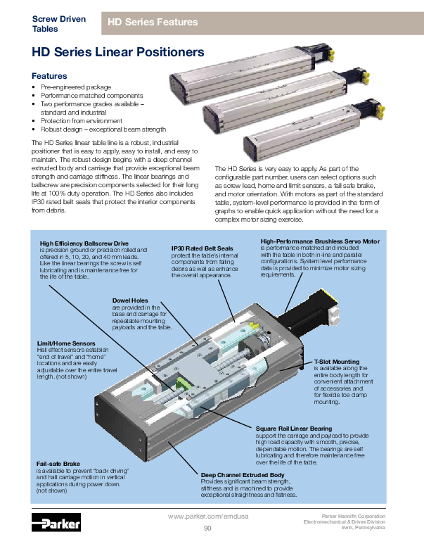
The HD Series linear table line is a robust, industrial positioner that is easy to apply, easy to install, and easy to maintain. The robust design begins with a deep channel extruded body and carriage that provide exceptional beam strength and carriage stiffness. The linear bearings and ballscrew are precision components selected for their long life at 100% duty operation. The HD Series also includes IP30 rated belt seals that protect the interior components from debris.
The HD Series is very easy to apply. As part of the configurable part number, users can select options such as screw lead, home and limit sensors, a fail safe brake, and motor orientation. With motors as part of the standard table, system-level performance is provided in the form of graphs to enable quick application without the need for a complex motor sizing exercise.
High Efficiency Ballscrew Drive is precision ground or precision rolled and offered in 5, 10, 20, and 40 mm leads. Like the linear bearings the screw is self lubricating and is maintenance free for the life of the table.
IP30 Rated Belt Seals protect the table's internal components from falling debris as well as enhance the overall appearance.
High-Performance Brushless Servo Motor is performance-matched and included with the table in both in-line and parallel configurations. System level performance data is provided to minimize motor sizing requirements.
Dowel Holes are provided in the base and carriage for repeatable mounting payloads and the table.
Limit/Home Sensors Hall effect sensors establish "end of travel" and "home" locations and are easily adjustable over the entire travel length. (not shown)
T-Slot Mounting is available along the entire body length for convenient attachment of accessories and for flexible toe clamp mounting.
Fail-safe Brake is available to prevent "back driving" and halt carriage motion in vertical applications during power down. (not shown)
Square Rail Linear Bearing support the carriage and payload to provide high load capacity with smooth, precise, dependable motion. The bearings are self lubricating and therefore maintenance free over the life of the table.
Deep Channel Extruded Body Provides significant beam strength, stiffness and is machined to provide exceptional straightness and flatness.
www.parker.com/emdusa 90
Parker Hannifin Corporation Electromechanical & Drives Division
Irwin, Pennsylvania
Life (Km)
Screw Driven Tables
HD Series Specifications
HD Series Life/Load Performance
The following performance information is provided as a supplement to the product specifications pages. The following graphs are used to establish the table life relative to the applied loads. The useful life of a linear table at full catalog specifications is dependent on the forces acting upon it. These forces include both static components resulting from payload weight and dynamic components due to acceleration/deceleration of the load. In multi-axes applications, the primary positioner at the bottom of the stack usually establishes the load limits for the combined axes. When determining life/load, it is critical to include the weight of all positioning elements that contribute to the load supported by the primary axis.
These charts are to be used in conjunction with the corresponding formulas found in the product manuals at www.parker.com/emdusa to establish the life/load for each bearing (4 per table).
Several dimensions, which are specific to each linear positioning table model, and the load geometry are required for these computations. These dimensions are supplied in the catalog information for each positioner. The dimensions are referenced as follows:
d1 bearing block center-to-center longitudinal spacing d2 bearing rail center-to-center lateral spacing d3 Rail center-to-carriage mounting surface
Refer to Parker's website www.parkermotion.com for moment loading and other engineering data.
Table Life/Load Compression (Normal) Load
100000
Life with Compression Load
HD085 HD125 HD185
10000
Catalog values are rated at 2,540 Km of life
1000 0
1000 2000 3000 4000 5000 6000 7000 8000 9000 10000
Load (N)
This graph provides evaluation of the support bearing
life/load characteristics. The curves show the life/load
relationship when the applied load is centered on
the carriage, normal (perpendicular) to the carriage
mounting surface.
For final evaluation of life vs load, including off center, tension, and side loads, refer to the charts and formulas found at www.parkermotion.com.
d1
d2
d3
HD085
51
42
53.5
HD125
65
70
57.5
HD185
105
115
42.0
Life (Km) Life (Km)
Bearing Life with Compression or Tension Load
100000
Life with Compression or Tension Load
HD085 HD125 HD185
10000
100000
Bearing Life with Side Load
Life with Side Load
HD085 HD125 HD185
10000
1000 0
Catalog values are rated at 2,540 Km of life
500
1000
1500
2000
2500
Load per Bearing (N)
3000
1000 0
Catalog values are rated at 2,540 Km of life
500
1000
1500
2000
2500
Load per Bearing (N)
3000
Parker Hannifin Corporation Electromechanical & Drives Division Irwin, Pennsylvania
www.parker.com/emdusa 91
Screw Driven Tables
HD085 Series Specifications
HD085 Series Linear Table 85 mm Wide Profile
Common Characteristics
Performance Bidirectional Repeatability (1) (µm) Duty Cycle Max Acceleration m/sec2 (in/sec2) Rated Normal Load (2) kgf (lbs) Rated Axial Loading (3) kgf (lbs) Drive Screw Efficiency % Max. Breakaway Torque Nm (ft-lbs) Running Torque Nm (ft-lbs) Linear Bearing Coefficient of Friction Carriage Weight kg (lbs)
Standard ±8.0 100%
20 (773) 170 (374) 90 (198)
90 0.21 (0.15) 0.18 (0.13)
0.01 0.9 (1.98)
Industrial ±50.0 100% 20 (773)
170 (374) 90 (198)
90 0.21 (0.15) 0.18 (0.13)
0.01 0.9 (1.98)
Travel Dependent Characteristics
Positional Accuracy (1)
(µm)
Straightness & Flatness Accuracy
(µm)
Travel Standard Industrial Standard Industrial
100
25
50
10
20
200
25
50
15
30
300
30
75
20
40
400
35
100
25
50
500
40
120
30
60
600
45
130
35
70
800
55
150
45
90
1000
65
200
55
110
1200
75
250
65
130
Max. Velocity (mm/sec.) @ Specified Lead
5 mm 10 mm 20 mm
370
740
1480
370
740
1480
370
740
1480
370
740
1480
370
740
1480
260
520
1040
180
360
720
--
240
480
--
170
340
Input Inertia (kg-m2 x 10-5) @ Specified Lead
5 mm 10 mm 20 mm
1.826 1.925 2.322
2.214 2.313 2.710
2.601 2.701 3.097
2.989 3.088 3.485
3.377 3.476 3.873
3.764 3.864 4.260
4.540 4.639 5.036
--
5.414 5.811
--
6.190 6.586
Total Table Weight (kg) 3.86 4.56 5.26 5.96 6.66 7.36 8.76 10.16 11.56
Motor Characteristics
M01x
M11x
M02x
M12x
SM232AE SM232AQ
Max. Voltage
340
340
Peak Current
8.3
8.3
RMS Current
2.0
2.0
Resistance
7.50
7.50
Inductance
2.90
2.90
Recommended Drive
S025
AR-04
* Series/Parallel denotes wiring of step motor to drive
M100 Series* HV232
170 1.38 1.38 3.41 12.28 E-AC
M100 Parallel* HV232
170 2.76 2.76 0.85 3.07 E-AC
(1) Accuracy and Repeatability apply to in-line motors only. Contact factory for parallel motor configurations. The accuracy and repeatability shown are for mechanics only and assume no error contribution from the motor. With standard 4000 count encoders an additional error must be added to both the accuracy and repeatability. For 5 mm lead add 1.25 microns, for 10 mm leads add 2.5 microns and for 20 mm leads add 5 microns of error to the accuracy and repeatability value stated above.
(2) Normal load capacities apply to centralized load on the linear bearing to a life of 2540 Km. Refer to life/load charts to determine life of your particular application. Normal load capacity ratings are to be used as a reference of linear bearing load to life rating. This value SHOULD NOT be used as a safe loading value since other application factors (such as mounting) affect the safe load rating.
(3) Axial load capacities assumes an average axial load on a 10 mm lead ball screw and a life of 2540 Km. Refer to life/load charts to determine life of your particular application.
www.parker.com/emdusa 92
Parker Hannifin Corporation Electromechanical & Drives Division
Irwin, Pennsylvania
HD085 Series Specifications
Screw Driven Tables
Thrust (N)
3000 2500 2000 1500 1000
HD085 Thrust versus Velocity
Peak 120VAC - 5mm Lead RMS Peak 120 VAC - 10mm Lead RMS Peak 120VAC - 5mm Lead RMS
500
Inertia Ratio
0 0.00 0.20 0.40 0.60 0.80 1.00 1.20 1.40 1.60
Velocity (m/s)
HD085 Inertia Ratios
10.00 9.00 8.00 7.00 6.00 5.00 4.00 3.00 2.00 1.00 0.00 0
5mm Lead 10mm Lead 20mm Lead
10
20
30
40
50
Load (Kg)
HD085 Acceleration Rates
25.0 20.0 15.0
Peak - 5mm Lead RMS Peak - 10mm Lead RMS Peak - 20mm Lead RMS
Acceleration (m/s/s)
10.0
5.0
0.0 0
10
20
30
40
50
Payload (Kg)
Parker Hannifin Corporation Electromechanical & Drives Division Irwin, Pennsylvania
www.parker.com/emdusa 93
Screw Driven Tables
HD125 Series Specifications
HD125 Series Linear Table 125 mm Wide Profile
Common Characteristics
Performance Bidirectional Repeatability (1) (µm) Duty Cycle Max Acceleration m/sec2 (in/sec2) Rated Normal Load (2) kgf (lbs) Rated Axial Loading (3) kgf (lbs) Drive Screw Efficiency % Max. Breakaway Torque Nm (ft-lbs)
0 to 1000 mm Travel 1200 to 1500 mm Travel Running Torque Nm (ft-lbs)) 0 to 1000 mm Travel 1200 to 1500 mm Travel Linear Bearing Coefficient of Friction Carriage Weight kg (lbs)
Standard ±8.0 100%
20 (773) 630 (1390)
90 (198) 90
Industrial ±50.0 100% 20 (773)
630 (1390) 90 (198) 90
0.25 (0.18) 0.25 (0.18) 0.35 (0.26) 0.35 (0.26)
0.21 (0.15) 0.32 (0.24)
0.01
2.2 (4.84)
0.21 (0.15) 0.32 (0.24)
0.01
2.2 (4.84)
Travel Dependent Characteristics
Positional Accuracy(1)
(µm)
Straightness & Flatness
Accuracy (µm)
Travel Std
Ind
Std
Ind
200
25
50
15
30
300
30
75
20
40
400
35
100
25
50
500
40
120
30
60
600
45
130
35
70
800
55
150
45
90
1000
65
200
55
110
1200
75
200
65
130
1500
90
300
80
150
Max. Velocity (mm/sec.) @ Specified Lead
5 mm 10 mm 20 mm 40 mm
370 740 1480 2240
370 740 1480 2240
370 740 1480 2240
315 630 1260 2240
240
480
960 1920
155
310
620 1240
--
212 424 848
--
--
420 840
--
--
280 560
Input Inertia (kg-m2 x 10-5) @ Specified Lead
5 mm 10 mm 20 mm 40 mm
3.061 3.416 4.834 14.386
3.449 3.804 5.222 15.612
3.837 4.191 5.610 16.837
4.224 4.579 5.997 18.062
4.612 4.967 6.385 19.287
5.387 5.742 7.160 7.936
-- 6.517 7.936 24.189
--
-- 21.577 27.251
--
-- 25.253 30.927
Total Table Weight
(kg) 11.50 12.75 14.00 15.25 16.50 19.00 21.50 24.00 25.75
Motor Characteristics
M01x
M11x
M02x
M12x
SM232AE SM232AQ
Max. Voltage
340
340
Peak Current
8.3
8.3
RMS Current
2.0
2.0
Resistance
7.50
7.50
Inductance
2.90
2.90
Recommended Drive
S025
AR-04
* Series/Parallel denotes wiring of step motor to drive
M03x SM233AE
340 8.1 1.9 9.65 4.08 S025
M13x SM233AQ
340 8.1 1.9 9.65 4.08 AR-04
M04x MPP921B
340 7.0 1.8 11.0 47.0 S025
M14x MPP921B
340 7.0 1.8 11.0 47.0 AR-04
M100 Series* HV232
170 1.38 1.38 3.41 12.28 E-AC
M100 Parallel* HV232
170 2.76 2.76 0.85 3.07 E-AC
(1) Accuracy and Repeatability apply to in-line motors only. Contact factory for parallel motor configurations. The accuracy and repeatability shown are for mechanics only and assume no error contribution from the motor. With standard 4000 count encoders an additional error must be added to both the accuracy and repeatability. For 5 mm lead add 1.25 microns, for 10 mm leads add 2.5 microns and for 20 mm leads add 5 microns of error to the accuracy and repeatability value stated above.
(2) Normal load capacities apply to centralized load on the linear bearing to a life of 2540 Km. Refer to life/load charts to determine life of your particular application. Normal load capacity ratings are to be used as a reference of linear bearing load to life rating. This value SHOULD NOT be used as a safe loading value since other application factors (such as mounting) affect the safe load rating.
(3) Axial load capacities assumes an average axial load on a 10 mm lead ball screw and a life of 2540 Km. Refer to life/load charts to determine life of your particular application.
www.parker.com/emdusa 94
Parker Hannifin Corporation Electromechanical & Drives Division
Irwin, Pennsylvania
HD125 Series Performance
HD125 Series Specifications
Screw Driven Tables
Thrust (N)
2500 2000 1500 1000
500 0 0.00
HD125/HD185 Thrust versusHVDe1lo2c5itTyhrust versus VelociHtyD125/HD185 Thrust versus Velocity
Peak - 5mm Lead - M01x, M11x 120VAC RMS Peak - 10mm Lead - M03x, M13x 120VAC RMS Peak - 20mm Lead - M03x, M13x 120VAC RMS
2500 2000 1500 1000
Peak - 20mm Lead - M04x, M14x RMS Peak - 40mm Lead - M04x, M14x RMS
Thrust (N)
500
0.50
1.00
1.50
2.00
2.50
3.00
Velocity (m/s)
0
0.00
0.50
1.00
1.50
2.00
2.50
3.00
Velocity (m/s)
HD125 Inertia Ratios HD125 Inertia Ratios
HD125 Inertia Ratios
10.00 9.00 8.00 7.00 6.00 5.00 4.00 3.00 2.00 1.00 0.00 0
5mm Lead - M01x, M11x 10mm Lead - M03x, M13x 20mm Lead (<=800mm) - M03x, M13x 20mm Lead (>800mm) - M03x, M13x
20
40
60
Payload (Kg)
10.00 9.00 8.00 7.00
20mm Lead (>800mm) - M04x, M14x
40mm Lead M04x,M14x
Inertia Ratio
6.00
5.00
4.00
3.00
2.00
1.00
0.00
80
100
0
20
40
60
Payload (Kg)
80
100
Inertia Ratio
Acceleration Rate (m/s/s)
25.0 20.0 15.0 10.0
5.0 0.0
0
HD125 Acceleration RateHsD125 Acceleration Rates
Peak - 5mm Lead - M01x, M11x RMS Peak - 10mm Lead - M03x, M13x RMS Peak - 20mm Lead (<=800mm) - M03x, M13x RMS Peak - 20mm Lead (>800mm) - M03x, M13x RMS
25.0 20.0 15.0
HD125 Acceleration Rates
Peak - 20mm Lead (>800mm) - M04x, M14x RMS Peak - 40mm Lead - M04x, M14x RMS
Acceleration Rate (m/s/s)
10.0
5.0
0.0
20
40
60
80
100
0
Payload (Kg)
20
40
60
80
100
Payload (Kg)
Parker Hannifin Corporation Electromechanical & Drives Division Irwin, Pennsylvania
www.parker.com/emdusa 95
Screw Driven Tables
HD185 Series Specifications
HD185 Series Linear Table 185 mm Wide Profile
Common Characteristics
Performance Bidirectional Repeatability (1) (µm) Duty Cycle Max Acceleration m/sec2 (in/sec2) Rated Normal Load (2) kgf (lbs) Rated Axial Loading (3) kgf (lbs) Drive Screw Efficiency % Max. Breakaway Torque Nm (ft-lbs)
0 to 1000 mm Travel 1200 to 1600 mm Travel Running Torque Nm (ft-lbs) 0 to 1000 mm Travel 1200 to 1600 mm Travel Linear Bearing Coefficient of Friction Carriage Weight kg (lbs)
Standard Industrial
±8.0
±50.0
100%
100%
20 (773) 20 (773)
1470 (3241) 1470 (3241)
90 (198) 90 (198)
90
90
0.32 (0.24) 0.32 (0.24) 0.38 (0.28) 0.38 (0.28) )
0.21 (0.15) 0.35 (0.26)
0.01
3.6 (7.92)
0.21 (0.15) 0.35 (0.26)
0.01
3.6 (7.92)
Travel Dependent Characteristics
Positional Accuracy(1)
(µm)
Straightness & Flatness
Accuracy (µm)
Travel Std
Ind
Std
Ind
300
30
75
20
40
400
35
100
25
50
500
40
120
30
60
600
45
130
35
70
800
55
150
45
90
1000 65
200
55
110
1200
75
235
65
130
1400
85
250
75
150
1600
95
300
85
180
Max. Velocity (mm/sec.) @ Specified Lead
5 mm 10 mm 20 mm 40 mm
370 740 1480 2240
370 740 1480 2240
355 710 1420 2240
270 540 1080 2000
165
330
660 1320
--
230
460
920
--
--
440 880
--
--
340 680
--
--
260 520
Input Inertia (kg-m2 x 10-5) @ Specified Lead
5 mm 10 mm 20 mm 40 mm
3.446 4.174 7.087 23.178
3.833 4.562 7.475 24.403
4.221 4.949 7.862 25.628
4.609 5.337 8.250 26.854
5.384 6.112 9.025 29.304
-- 6.888 9.801 31.754
--
-- 22.253 34.205
--
-- 25.003 36.655
--
-- 27.454 39.106
Weight (kg) Total 22.9 24.6 26.4 28.2 31.7 35.2 38.7 42.2 45.8
Motor Characteristics
M01x SM232AE
M11x SM232AQ
Max. Voltage
340
340
Peak Current
8.3
8.3
RMS Current
2.0
2.0
Resistance
7.50
7.50
Inductance
2.90
2.90
Recommended Drive
S025
AR-04
* Series/Parallel denotes wiring of step motor to drive
M03x SM233AE
340 8.1 1.9 9.65 4.08 S025
M13x SM233AQ
340 8.1 1.9 9.65 4.08 AR-04
M04x MPP921B
340 7.0 1.8 11.0 47.0 S025
M14x MPP921B
340 7.0 1.8 11.0 47.0 AR-04
(1) Accuracy and Repeatability apply to in-line motors only. Contact factory for parallel motor configurations. The accuracy and repeatability shown are for mechanics only and assume no error contribution from the motor. With standard 4000 count encoders an additional error must be added to both the accuracy and repeatability. For 5 mm lead add 1.25 microns, for 10 mm leads add 2.5 microns and for 20 mm leads add 5 microns of error to the accuracy and repeatability value stated above.
(2) Normal load capacities apply to centralized load on the linear bearing to a life of 2540 Km. Refer to life/load charts to determine life of your particular application. Normal load capacity ratings are to be used as a reference of linear bearing load to life rating. This value SHOULD NOT be used as a safe loading value since other application factors (such as mounting) affect the safe load rating.
(3) Axial load capacities assumes an average axial load on a 10 mm lead ball screw and a life of 2540 Km. Refer to life/load charts to determine life of your particular application.
www.parker.com/emdusa 96
Parker Hannifin Corporation Electromechanical & Drives Division
Irwin, Pennsylvania
HD185 Series Performance
HD185 Series Specifications
Screw Driven Tables
Thrust (N)
2500 2000 1500 1000
500 0 0.00
HD125/HD185 Thrust versusHVDe1lo8c5itTyhrust versus VelociHtyD125/HD185 Thrust versus Velocity
Peak - 5mm Lead - M01x, M11x 120VAC RMS Peak - 10mm Lead - M03x, M13x 120VAC RMS Peak - 20mm Lead - M03x, M13x 120VAC RMS
2500 2000 1500 1000
Peak - 20mm Lead - M04x, M14x RMS Peak - 40mm Lead - M04x, M14x RMS
Thrust (N)
500
0.50
1.00
1.50
2.00
2.50
3.00
Velocity (m/s)
0
0.00
0.50
1.00
1.50
2.00
2.50
3.00
Velocity (m/s)
Inertia Ratio
HD185 Inertia Ratios HD185 Inertia Ratios
HD125 Inertia Ratios
20.00 18.00 16.00 14.00 12.00
5mm Lead - M01x, M11x 10mm Lead - M03x, M13x 20mm Lead (<=800mm) - M03x, M13x 20mm Lead (>800mm) - M03x, M13x
10.00
8.00
6.00
4.00
2.00
0.00 0
50
100
150
Payload (Kg)
10.00 9.00 8.00 7.00
20mm Lead (>800mm) - M04x, M14x
40mm Lead M04x,M14x
Inertia Ratio
6.00
5.00
4.00
3.00
2.00
1.00
0.00
200
0
20
40
60
Payload (Kg)
80
100
Acceleration Rate (m/s/s)
25.0 20.0 15.0 10.0
5.0 0.0
0
Acceleration Rate (m/s/s)
HD185 Acceleration Rates HD185 Acceleration Rates
Peak - 5mm Lead - M01x, M11x RMS Peak - 10mm Lead - M03x, M13x RMS Peak - 20mm Lead (<=800mm) - M03x, M13x RMS Peak - 20mm Lead (>800mm) - M03x, M13x RMS
25.0 20.0 15.0 10.0
HD125 Acceleration Rates
Peak - 20mm Lead (>800mm) - M04x, M14x RMS Peak - 40mm Lead - M04x, M14x RMS
5.0
50
100
150
Payload (Kg)
0.0
200
0
20
40
60
80
100
Payload (Kg)
Parker Hannifin Corporation Electromechanical & Drives Division Irwin, Pennsylvania
www.parker.com/emdusa 97
Screw Driven Tables
HD Series Features and Options
HD Series Features and Options
Deep Channel Extruded Body
The foundation of the HD Series is an extruded body, designed to provide exceptional beam strength and rigidity with ease of use features, yet be aesthetically appealing. The extrusion cross section has a high moment of inertia that strengthens and stiffens the unit. This enables users to span unsupported distances or cantilever the axis with minimal or no need for stiffening brackets. As an example, an HD may be toe clamped directly to the structural beams in a machine frame as opposed to having a plate cut to size and machined flat to serve as the positioner's mounting surface. The elimination of the mounting plate reduces overall design time and machine cost.
Precision Machined Tolerances
The extruded base provides the basic shape of the positioner but in its raw form, lacks the precision needed for most applications. Parker's proprietary machining processes are used to cut rail seats and flatten the bottom of the extrusion to specifications better than jig plate. Some manufacturers will skip machining the bottom mounting surface to save cost but sacrifice precision and risk binding and other application problems. With the HD Series you gain the feature benefits of an extruded base and through Parker's machining capability, gain precision better than jig plate designs can offer.
Maintenance Free Linear Bearings
Supporting the payload in the HD Series is a precision ground linear bearing set that offers precise, smooth motion. The two-rail, four-bearing truck design provides high load capacity and is structured to handle cantilevered load unlike single rail designs. The linear bearings are self lubricating and therefore will not require re-lubrication for the life of the table.
IP30 Rated Environmental Protection
Often automation applications can be in dirty environments. For this reason the HD Series includes environmental protection beyond just a simple plate. The HD Series uses a combination of hard cover and belt seal to provide a significant level of environmental protection for the tables internal components. This is ideal for larger objects like nuts, bolts, fingers, and larger debris. The sealing system will provide a measure of protection for dust but is not impervious. For these applications, pressurizing the HD positioner can be very effective.
High-Performance Brushless Servo Motors
Included with the HD Series are high-performance brushless servo motors. These motors are performance-matched with the mechanical drive train and are inertia matched to maintain good load-torotor inertia ratios. Together, these characteristics offer excellent dynamic performance and stability.
As standard, the motors are offered in an in-line configuration and for space constrained applications may be mounted in a parallel configuration. The parallel design utilizes a belt and pulley to transfer torque and includes additional pulley support bearings to protect the motor shaft and screw shank from over tension and fatigue failures.
Finally, because the motors are included, system performance can be pre-calculated and presented in graphical form. For most applications, motor sizing is as simple as looking at a graph.
Zero Backlash Shaft Coupling
Included with the HD Series to transfer motor torque to the ballscrew is a high-performance shaft coupling. The coupling design uses stainless steel disks to transfer torque yet provide a measure of flexibility for slight shaft misalignments. The design is very lightweight and adds minimal inertia. The combination of high stiffness and low inertia maintains high natural frequencies, which is important for high performance applications.
www.parker.com/emdusa 98
Parker Hannifin Corporation Electromechanical & Drives Division
Irwin, Pennsylvania
HD Series Features and Options
Screw Driven Tables
Ground Ballscrew Drive Train (Standard Grade)
At the heart of the HD Series drive train is a preloaded, precision ground ballscrew. This highperformance component offers high-speed, 100% duty cycle operation with long life, plus the better precision and surface finish of a ground screw compared with a rolled screw enables more accurate and quieter operation.
As standard, the HD Series offers 5 mm, 10 mm, and 20 mm lead options with a 40 mm lead available as a special. For most travels, the screws are 15 mm in diameter with the longer 20 mm lead and all 40 mm lead screws increasing to 20 mm in diameter. Like the linear bearings, the screws are self lubricating and will not require relubrication for the table's life.
Mounting Features
The HD Series is designed for easy mounting. There are two basic methods of mounting an HD module into a machine. First, toe clamps (Part Number 101-2577-01) provide an easy method of bolting the HD down to a surface. For maximum flexibility, the toe clamps can be placed anywhere along the body extrusion and enable aligning mounting points with structural members of the machine frame. The second method utilizes taped holes in the base where the mounting hardware comes through the mounting surface into the HD module. The mounting pattern consists 4 tapped holes and 2 dowel holes and repeats at varying intervals depending on overall travel. See the HD Series drawings for hole location details.
Dowel Holes
As mentioned above the base of the HD Series includes dowel holes. These enable repeatable mounting within a machine. Further, the carriage of the HD also includes a set of dowel holes and is very useful for maintaining alignment if the payload is removed or replaced.
End Mounting
In many applications, the positioner may be mounted with the carriage stationary such that the body moves. For these applications, the end of the HD includes tapped and dowel holes for mounting of the payload to the HD body. In many cases this avoids the cost and time of designing an awkward bracket to wrap from the bottom of the positioner around to the end.
Home and Limit Sensors
As a standard option, home and end of travel limit sensors may be added to an HD positioner. These are industrially hardened, hall effect sensors that are triggered by a magnet mounted on the moving carriage. The sensors nest inside the extrusion T-slot and so do not add additional width or create obstructions. Further they are protected inside the T-slot which minimizes the opportunity for physical damage.
For maximum flexibility, sensors are adjustable over the entire length and magnets are included on both sides of the table so sensors can be attached on either side. The sensors are offered in 4 variants with NPN (sinking) or PNP (sourcing) outputs and in normally open (NO) or normally closed (NC) logic. The sensor cables extend 300 mm and terminate into a M3 connector. If purchased as part of the positioner (LH option) each sensor will include a 5 m extension cable (P/N: 003-2918-01).
Input Power Voltage Drop Cont. Current Electrical Protection
Enclosure
Wire Colors
Repeatability
10-30VDC
<= 2.5V
100mA
Short Circuit, Reverse Polarity, Power Up Pulse Suppression
IP67 Rated Polyamide Housing with PVC Cable Jacket
Brown Power (+) Black Signal
Blue Ground (-)
0.1 mm max
Spare Part Number
Output Type
P8S-GNCHX N.O.
Logic NPN (Sinking)
P8S-GPCHX N.O. PNP (Sourcing)
P8S-GMCHX N.C. NPN (Sinking)
P8S-GQCHX N.C. PNP (Sourcing)
003-2918-01 --
--
Cable Type
300 mm to M3 connector
300 mm to M3 connector
300 mm to M3 connector
300 mm to M3 connector
5.0 m Extension Cable
Parker Hannifin Corporation Electromechanical & Drives Division Irwin, Pennsylvania
www.parker.com/emdusa 99
Screw Driven Tables
HD085 Series Dimensions
HD085 Series Dimensions
10.0 Mtg. Surface
50.0 Ctr'd
40.0 Ctr'd
10.0 Mtg. Surface
"B" Mid Travel
"A" 88.0 Mtg. Surface 40.0 40.0
Dowel Holes for 6mm Pins 2 Holes (Top) Slip Fit
Top View
4 Mtg. Holes (Top) M6 x 1.0 Thd.
2D & 3D CAD Download from files parkermotion.com
Dimensions (mm)
CL 57.2 85.0
2.0 70.0
26.0
"A"
"E"
Front View
"1/2 A" +4.5
50.0
50.0
Typ.
Typ.
See Detail A on page 101
"C" Mtg. Holes
M5 x 0.8 Thd.
8.0
(Base)
"F" "G" CL Motor 41.25
77.0 Ctr'd
Model HD085T01 HD085T02 HD085T03 HD085T04 HD085T05 HD085T06 HD085T07 HD085T08 HD085T09 HD085T10 HD085T11 HD085T12
85.0
Bottom View
Dowel Holes for 5mm Pins
76.0
"D" Holes
38
44.0 9.0
6.006 dia. 2 holes
Drill and tap M5 x .8 4holes
37.50 42.55
85.0
Travel 100 200 300 400 500 600 700 800 900 1000 1100 1200
A 311 411 511 611 711 811 911 1011 1111 1211 1311 1411
Dimensions
B
C
D
135 4
2
185 12
6
235 12
6
285 12
6
335 12
6
385 12
6
435 12
6
485 12
6
535 12
6
585 12
6
635 12
6
685 12
6
Slot for Std.
M4 Square Nut
4 Slots
7.5
Typ.
30.0
10.25
36.7
4.2
Typ.
Typ.
View showing slots in extruded base
182 5.5 Typ.
H
Parallel Motor Mounts for "M" Motor Codes Shown in Position A
E
160
210
260
310
360
Dimensions
410
Motor Model
E
F
G
H
460
M000
No Motor
0
510
M010 SM232AE-TPSN 134.5 57.2 69.8 163
560
M020 SM232AE-TPSB 168.0 57.2 69.8 198
610
M100
HV232-D2-10 79.2 57.2 69.8
660
M110 SM232AQ-TPSN 134.5 57.2 69.8 163
710
M020 SM232AQ-TPSB 168.0 57.2 69.8 198
www.parker.com/emdusa 100
Parker Hannifin Corporation Electromechanical & Drives Division
Irwin, Pennsylvania
Screw Driven Tables
2D & 3D CAD Download from files parkermotion.com
HD085 Series Dimensions
HD085 Parallel Motor Options
182.5
ADDER TO "A" LENGTH DIM 43.3 19.5
20.8 85
95.8
10.5
"T" THICKNESS
"P" PILOT DIA.
Dimensions (mm)
67
40.3
33.5
"S" SHAFT DIA.
"M" TAPPED HOLE ON A "N" B.C.D.
NOTE : SHOWN AS SIDE"A" ("B" IS MIRROR IMAGE . ROTATED 180' ABOUT TABLE SCREW CENTERLINE)
Motor Adapter
Dimensions
Assembly
Part Number
M
P
S
T
A011-HD085
or
M4 x 0.7
30.0
8.0
6.5
B011-HD085
A232-HD085
or
M5 x 0.8
38.1
9.53
8.0
B232-HD085
Example Motors Yaskawa SGMAH-01, SGM-01
Kollmorgen AKM1X-AN Allen Bradley Y-1002, Y-1003
Parker SM23X , BE23X
Parker Hannifin Corporation Electromechanical & Drives Division Irwin, Pennsylvania
www.parker.com/emdusa 101
Screw Driven Tables
HD085 Series Dimensions
HD085 Motor Flange/Coupling Assembly Options
DIM "C" DIMENSION MOTOR FLANGE SITS ABOVE CARRIAGE SURFACE
2D & 3D CAD Download from files parkermotion.com
Dimensions (mm)
SEE DETAIL A
MTR SHAFT LENGTH Ø THRU HOLE MTG.
DETAIL A
DIM "B" TOTAL MOTOR ADAPTER(S) THICKNESS
DIM "A" LOCATION OF COUPLING FACE TO MOTOR FACE
MTR B.C.D.
MTR PILOT DIAMETER MTR SHAFT DIAMETER
MTR PILOT THICKNESS
Dimensions
Required Motor Specifications
Motor Adapter Assembly
Bolt Bolt Pilot Pilot Circle Hole Shaft Shaft
Part Number A B C Dia. Depth Dia. Size Dia. Length
Example Motors
F011-HD085 12.0 8.0 -- 30.0 3.0 46.0 4.5 8.0 25.0
Yaskawa SGMAH-01, SGM-01 Kollmorgen AKM1X-AN
Allen Bradley Y-1002, Y-1003
F012-HD085 12.0 8.0 -- 30.0 3.0 46.0 4.5 6.0 25.0
Yaskawa SGMAH-A1XXF4, SGMAH-A3XXF4X, SGM-03,SGM-A5
F021-HD085 15.0 10.5 -- 50.0 3.0 60.0 4.5 8.0 24.0
Allen Bradley LD-2003
F031-HD085 12.0 8.0 -- 40.0 3.0 63.0 5.5 9.0 20.0
Parker SMB60/HDY55 Allen Bradley MPL1510/1520/1530
F041-HD085 12.0 8.0 -- 40.0 3.0 63.0 4.5 9.0 20.0
Kollmorgen AKM2X-AN Indramat MKD025
F051-HD085 15.0 10.5 -- 50.0 3.0 70.0 5.5 8.0 25.0
Yaskawa SGMP-01, SGMPH-01-XXXX
F061-HD085 20.0* 18.0 1.3 50.0 3.0 70.0 5.5 14.0 30.0
Yaskawa SGMAH-02XXF4X, SGMAH-04XXF4X, SGM-02, SGM-04
Allen Bradley Y-2006, Y-2012
F071-HD085 10.0* 10.5 2.0 60.0 3.0 75.0 5.5 11.0 23.0
Parker J070/NO70/HDY70 Allen Bradley MPL210/220/230
Kollmorgen B102/BH-122
F072-HD085 10.0* 10.5 2.0 60.0 3.0 75.0 5.5 14.0
30.0
Kollmorgen B104/B106, M-103/105/107, AKM3XAN, BH-124/126
N231-HD085 12.0 8.0 -- 38.1 3.0 66.675 5.5 6.35 20.0
Parker ES23X Allen Bradley N-2302, N-2304 Animatics SM2310D, SM2320D
N232-HD085 12.0 8.0 -- 38.1 3.0 66.675 5.5 9.525 20.0-31.0
Parker SM23X , BE23X
N233-HD085 10.0* 8.0 -- 38.1 3.0 66.675 4.5 12.7 20.0
Yaskawa SGMAH-0XXN2XX, SGMAH-04XXN2XX NEMA 23 Face
N341-HD085 20.0* 18.0 12.6 73.03 3.0 98.425 5.5 12.5 37.0
Parker HV/LV34
* Note: Coupling must be mounted to motor first. Distance of coupling face to motor face.
www.parker.com/emdusa 102
Parker Hannifin Corporation Electromechanical & Drives Division
Irwin, Pennsylvania
Parker Hannifin Corporation Electromechanical & Drives Division Irwin, Pennsylvania
www.parker.com/emdusa 103
Screw Driven Tables
Screw Driven HD125 Series Dimensions
Tables
HD125 Series Dimensions
"A" 150.0 130.0
2D & 3D CAD Download from files parkermotion.com
Dimensions (mm)
18.0 Brake Option
2.5
85.0 (to carriage)
"B" Mid Travel
Top View
"A"
Front View
Ø 6.006 H7 2 Holes Per Set
M6 X1.0 X 12.0DP 4 Holes Per Set
CL
"L"
See Detail A on page 103
CL
"M" "N"
49.5
105.0 Ctr'd.
100.0 100.0
125.0
45.0
45.0
100.0
100.0
100.0 100.0
100.0 100.0
100.0
100.0 "C"
"D"
"E"
"F"
"G"
"A"
Bottom View 130.0
110.0
M6 X 1.0 X 10.0 Deep
55.0
8 Holes
50
30.0
Slot for std M4 square nut 4 slots
34.0
82.0
39.0 22.0
37.5
265
CL
75.0
10.25
6.006 Dia. Holes
End View
Qty. (4) Holes M6 X 1.0 Tapped
27.5 55.0
6.006 Dia. H7 2 Holes
Top Carriage View
P
Parallel Motor Mounts for "M" Motor Codes
Shown in Position A
Dimensions
Model Travel A
B
C
D
E
F
G
HD125T02 200 508.0 239.5
135.0
HD125T03 300 608.0 289.5 50.0 185.0 320.0
HD125T04 400 708.0 339.5 50.0 235.0 420.0
HD125T05 500 808.0 389.5 50.0 285.0 520.0
HD125T06 600 908.0 439.5 50.0 335.0 620.0
HD125T08 800 1108.0 539.5 50.0 435.0 820.0
HD125T10 1000 1308.0 639.5 50.0 535.0 1020.0
HD125T12 1200 1558.0 737.0 50.0 342.5 635.0 927.5 1220.0
HD125T15 1500 1858.0 887.0 50.0 417.5 785.0 1152.5 1520.0
Dimensions
Motor Model
LMN P
M000
No Motor
0
M010 SM232AE-TPSN 167 57.2 78.1 208
M030 SM233AE-TPSN 192 57.2 78.1 233
M040 CMP921B1E 195 89.4 94.2
M100 HV232-D2-10 102 57.2 78.1
M110 SM232AE-TPSN 167 57.2 78.1 208
M130 SM233AE-TPSN 192 57.2 78.1 233
M140 CMP921B3E 195 89.4 94.2
www.parker.com/emdusa 104
Parker Hannifin Corporation Electromechanical & Drives Division
Irwin, Pennsylvania
2D & 3D CAD Download from files parkermotion.com
HD125 Parallel Motor Options
35
28
"T" THICKNESS
"P" PILOT DIA.
HD125 Series Dimensions
Dimensions (mm)
265
50.8 ADDER TO "A" LENGTH DIM
77.5
125
140
82
41
49
"S" SHAFT DIA.
"M" TAPPED HOLE ON A "N" B.C.D.
NOTE : SHOWN AS SIDE"B" ("A" IS MIRROR IMAGE . ROTATED 180' ABOUT TABLE SCREW CENTERLINE)
Motor Adapter Assembly
Dimensions
Part Number
M
N
P
S
T
A021-HD125 or B021-HD125
M4 x 0.7
60.0
50.0
8.0
7.5
A031-HD125 or B031-HD125
M5 x 0.8
63.0
40.0
9.0
7.5
A041-HD125 or B041-HD125
M4 x 0.7
63.0
40.0
9.0
7.5
A061-HD125 or B061-HD125
M5 x 0.8
70.0
50.0
8.0
10.0
A062-HD125 r B062-HD125
M5 x 0.8
70.0
50.0
14.0
10.0
A071-HD125 or B071-HD125
M5 x 0.8
75.0
60.0
11.0
A081-HD125 or B081-HD125
M6 x 1.0
90.0
70.0
14.0
10.0
A101-HD125 or B101-HD125
M6 x 1.0
95.0
50.0
14.0
10.0
A111-HD125 or B111-HD125
M6 x 1.0
100.0
80.0
14.0
10.0
A121-HD125 or B121-HD125
M6 x 1.0
100.0
80.0
16.0
8.0*
A231-HD125 or B231-HD125
M5 x 0.8
66.68
38.1
6.35
10.0
A232-HD125 or B232-HD125
M5 x 0.8
66.68
38.1
9.53
10.0
A233-HD125 or B233-HD125
M4 x 0.7
66.68
38.1
12.7
10.0
A341-HD125 or B341-HD125
M5 x 0.8
98.43
73.03
6.35
15.0
A342-HD125 or B342-HD125
M5 x 0.8
98.43
73.03
12.7
15.0
*Not outer support bearing assembly block (no 35 mm dimension pulley on motor shaft.
* Note: Coupling must be mounted to motor first. Distance of coupling face to motor face.
Parker Hannifin Corporation Electromechanical & Drives Division Irwin, Pennsylvania
www.parker.com/emdusa 105
Example Motors
Allen Bradley LD-2003
Parker SMB60/HDY55 Allen Bradley MPL1510/1520/1530
Kollmorgen AKM2X-AN Indramat MKD025
Yaskawa SGMP-01, SGMPH-01-XXXX
Yaskawa SGMAH-02XXF4X, SGMAH-04XXF4X, SGM-02, SGM-04
Allen Bradley Y-2006, Y-2012 Parker J070/NO70/HDY70
Allen Bradley MPL210/220/230 Kollmorgen B102/BH-122 Yaskawa SGMPH-02XXX,
SGMPH-04XXX, SGMP-02, SGMP-04
Indramat MKD041
Parker JO92X/NO92X
Kollmorgen AKM4X-AN Mounting Code
Parker ES23X Allen Bradley N-2302, N-2304 Animatics SM2310D, SM2320D
Parker SM23X , BE23X
Yaskawa SGMAH-0XXN2XX, SGMAH-04XXN2XX NEMA 23 Face
Parker HV/LV34
Parker BE34
Screw Driven HHDD121525SeSreierisesDDimimenesnisoinosns
Tables HD125 Motor Flange/Coupling Assembly Options
DIM "C" DIMENSION MOTOR FLANGE SITS ABOVE CARRIAGE SURFACE
2D & 3D CAD Download from files parkermotion.com
Dimensions (mm)
SEE DETAIL A
MTR SHAFT LENGTH Ø THRU HOLE MTG.
MTR B.C.D.
MTR PILOT DIAMETER MTR SHAFT DIAMETER
MTR PILOT THICKNESS
DETAIL A
Motor Adapter Assembly
Part Number A B F021-HD125 15.0 10.5 F031-HD125 12.0 8.0 F041-HD125 12.0 7.5 F061-HD125 15.0 12.0 F062-HD125 15.0 12.0
F071-HD125 12.0 10.5
F072-HD125 12.0 10.5 F081-HD125 15.0* 22.0 F082-HD125 15.0* 22.0 F091-HD125 15.0* 22.0 F101-HD125 15.0* 22.0 F111-HD125 15.0* 20.0 F121-HD125 20.0* 28.0 F122-HD125 25.0* 33.0 N231-HD125 12.0 8.0 N232-HD125 12.0 8.0 N233-HD125 10.0* 8.0 N341-HD125 15.0 20.0 N342-HD125 15.0* 20.0
DIM "B" TOTAL MOTOR ADAPTER(S) THICKNESS
DIM "A" LOCATION OF COUPLING FACE TO MOTOR FACE
Dimensions
Required Motor Specifications
Bolt Bolt Pilot Pilot Circle Hole Shaft Shaft C Dia. Depth Dia. Size Dia. Length
Example Motors
-- 50.0 3.0 60.0 4.5 8.0 24.0
Allen Bradley LD-2003
-- 40.0 3.0 63.0 5.5 9.0 20.0
Parker SMB60/HDY55 Allen Bradley MPL1510/1520/1530
-- 40.0 3.0 63.0 4.5 9.0 20.0
Kollmorgen AKM2X-AN Indramat MKD025
-- 50.0 3.0 70.0 5.5 8.0 25.0
Yaskawa SGMP-01, SGMPH-01-XXXX
-- 50.0 3.0 70.0 5.5 14.0 30.0
Yaskawa SGMAH-02XXF4X, SGMAH-04XXF4X, SGM-02, SGM-04
Allen Bradley Y-2006, Y-2012
-- 60.0 3.0 75.0 5.5 11.0 23.0
Parker J070/NO70/HDY70 Allen Bradley MPL210/220/230
Kollmorgen B102/BH-122
-- 60.0 3.0 75.0 5.5 14.0
30.0
Kollmorgen B104/B106, M-103/105/107, AKM3XAN, BH-124/126
4.5 70.0 3.5 90.0 6.6 14.0 30.0
Yaskawa SGMPH-02XXX, SGMPH-04XXX, SGMP-02, SGMP-04
4.5 70.0 3.5 90.0 6.6 16.0 30.0-40.0
Yaskawa SGMAH-08 SGM-08 Allen Bradley Y-3023
4.5 70.0 3.5 90.0 5.5 14.0 30.0
Allen Bradley LD-3009
7.0 50.0 3.5 95.0 6.6 14.0 30.0
Indramat MKD041
7.0 80.0 3.5 100.0 6.6 14.0 30.0
Parker JO92X/NO92X
7.0 80.0 3.5 100.0 6.6 16.0 30.0-40.0
Parker MPP92X Allen Bradley MPL310/320/330, LD-4012
7.0 80.0 3.5 100.0 6.6 19.0 40.0
Kollmorgen AKM4X-AN Mounting Code
-- 38.1 3.0 66.675 5.5 6.35 20.0
Parker ES23X Allen Bradley N-2302, N-2304 Animatics SM2310D, SM2320D
-- 38.1 3.0 66.675 5.5 9.525 20.0-31.0
Parker SM23X , BE23X
-- 38.1 3.0 66.675 4.5 12.7 20.0
Yaskawa SGMAH-0XXN2XX, SGMAH-04XXN2XX NEMA 23 Face
7.0 73.03 3.0 98.425 5.5 12.5 37.0
Parker HV/LV34
7.0 73.03 3.0 98.425 5.5 12.7 30.0
Parker BE34
www.parker.com/emdusa 106
Parker Hannifin Corporation Electromechanical & Drives Division
Irwin, Pennsylvania
Parker Hannifin Corporation Electromechanical & Drives Division Irwin, Pennsylvania
www.parker.com/emdusa 107
Screw Driven Tables
Screw Driven Tables
HD185 Series Dimensions
HD185 Series Dimensions
"A"
175.0 155.0
2D & 3D CAD Download from files parkermotion.com
Dimensions (mm)
"L"
25.0 Brake Option
2 95
43.5
200.0
100.0
"B" Mid Travel
Top View
Front View
"B" 100.0 100.0
"C"
"C"
162.0 Typ. 100.0 100.0
100.0 100.0
"L"
"N" CL "M"
53.0 See Detail A on page 105
200.0
42.4
100.0
Ø8.008 H7 2 Holes Per Set
Bottom View
M8X1.25 X12.0DP 4 Holes Per Set
155.0
Carriage Length
M8 X 1.25 X12.0 DP.
8 Holes
140.0
185.0 70.0
45.5
47.50
90.0
6.6 dia. 2 holes
30.0 Typ. 30.0
34.092.0 49.5 32.5
126.0
330
63.0
10.25 Typ.
Qty. (4) Holes M6 X 1.0 Tapped
End View
35.0
70.0
Carriage Top View
Ø8.00 H7 Qty.(2) Holes
P
Parallel Motor Mounts for "M" Motor Codes
Shown in Position A
Model HD185T03 HD185T04 HD185T05 HD185T06 HD185T08 HD185T10 HD185T12 HD185T14 HD185T16 HD185T18 HD185T20
Travel 300 400 500 600 800 1000 1200 1400 1600 1800 2000
A 585.9 685.9 785.9 885.9 1085.9 1285.9 1485.9 1685.9 1885.9 2085.9 2285.9
Dimensions B
293.5 343.5 393.5 443.5 543.5 643.5 743.5 843.0 943.0 1043.0 1143.5
C 200.0 250.0 300.0 350.0 400.0
Dimensions
Motor Model
L
M
N
P
M000
No Motor
0
M010 SM232AE-TPSN 126.8 57.2 81.6 208
M030 SM233AE-TPSN 152.2 57.2 81.6 233
M040
CMP921B1E 170.1 89.4 91.7 207
M110 SM232AQ-TPSN 126.8 57.2 81.6 208
M130 SM233AQ-TPSN 152.2 57.2 81.6 233
M140
CMP921B3E 170.1 89.4 91.7 277
www.parker.com/emdusa 108
Parker Hannifin Corporation Electromechanical & Drives Division
Irwin, Pennsylvania
2D & 3D CAD Download from files parkermotion.com
HD185 Series Dimensions
New HD185 Parallel Motor Options
330
35
28
"T" THICKNESS
82.5
185
175 "P" PILOT DIA.
Dimensions (mm)
50.8 ADDER TO "A" LENGTH DIM
Screw Driven Tables
92
46
52
"S" SHAFT DIA.
"M" TAPPED HOLE ON A "N" B.C.D.
NOTE : SHOWN AS SIDE"B" ("A" IS MIRROR IMAGE . ROTATED 180' ABOUT TABLE SCREW CENTERLINE)
Motor Adapter Assembly
Dimensions
Part Number
M
N
P
S
T
A021-HD185 or B021-HD185
M4 x 0.7
60.0
50.0
8.0
7.5
A031-HD185 or B031-HD185
M5 x 0.8
63.0
40.0
9.0
7.5
A041-HD185 or B041-HD185
M4 x 0.7
63.0
40.0
9.0
7.5
A061-HD185 or B061-HD185
M5 x 0.8
70.0
50.0
8.0
10.0
A062-HD185 or B062-HD185
M5 x 0.8
70.0
50.0
14.0
10.0
A071-HD185 or B071-HD185
M5 x 0.8
75.0
60.0
11.0
A081-HD185 or B081-HD185
M6 x 1.0
90.0
70.0
14.0
10.0
A082-HD185 or B082-HD185
M5 x 0.8
90.0
70.0
14.0
10.0
A101-HD185 or B101-HD185
M6 x 1.0
95.0
50.0
14.0
10.0
A111-HD185 or B111-HD185
M6 x 1.0
100.0
80.0
14.0
10.0
A121-HD185 or B121-HD185
M6 x 1.0
100.0
80.0
16.0
8.0*
A231-HD185 or B231-HD185
M5 x 0.8
66.68
38.1
6.35
10.0
A232-HD185 or B232-HD185
M5 x 0.8
66.68
38.1
9.53
10.0
A233-HD185 or B233-HD185
M4 x 0.7
66.68
38.1
12.7
10.0
A341-HD185 or B341-HD185
M5 x 0.8
98.43
73.03
6.35
15.0
A342-HD185 or B342-HD185
M5 x 0.8
98.43
73.03
12.7
15.0
*Not outer support bearing assembly block (no 35 mm dimension pulley on motor shaft.
Example Motors
Allen Bradley LD-2003
Parker SMB60/HDY55 Allen Bradley MPL1510/1520/1530
Kollmorgen AKM2X-AN Indramat MKD025
Yaskawa SGMP-01, SGMPH-01-XXXX
Yaskawa SGMAH-02XXF4X, SGMAH-04XXF4X, SGM-02, SGM-04
Allen Bradley Y-2006, Y-2012 Parker J070/NO70/HDY70
Allen Bradley MPL210/220/230 Kollmorgen B102/BH-122 Yaskawa SGMPH-02XXX,
SGMPH-04XXX, SGMP-02, SGMP-04 Yaskawa SGMAH-08 SGM-08 Allen Bradley Y-3023
Indramat MKD041
Parker JO92X/NO92X
Parker MPP92X Allen Bradley MPL310/320/330, LD-4012
Parker ES23X Allen Bradley N-2302, N-2304 Animatics SM2310D, SM2320D
Parker SM23X , BE23X
Yaskawa SGMAH-0XXN2XX, SGMAH-04XXN2XX NEMA 23 Face
Parker HV/LV34
Parker BE34
Parker Hannifin Corporation Electromechanical & Drives Division Irwin, Pennsylvania
www.parker.com/emdusa 109
Screw Driven Tables
HD185 Series Dimensions
HD185 Motor Flange/Coupling Assembly Options
2D & 3D CAD Download from files parkermotion.com
Dimensions (mm)
SEE DETAIL A
"B" MOTOR ADAPTER LENGTH ADDER BEYOND ENDCAPS
MTR SHAFT LENGTH Ø THRU HOLE MTG.
DETAIL A
"A" DIMENSION LOCATION OF COUPLING FACE TO MOTOR FACE
MTR PILOT DIAMETER MTR B.C.D. MTR SHAFT DIAMETER
MTR PILOT THICKNESS
Dimensions
Required Motor Specifications
Motor Adapter
Bolt Bolt
Assembly
Pilot Pilot Circle Hole Shaft Shaft
Part Number A
B Dia. Depth Dia. Size Dia. Length
F021-HD185 15.0 -- 50.0 3.0 60.0 4.5 8.0 24.0
F031-HD185 10.0 -- 40.0 3.0 63.0 5.5 9.0 20.0
F041-HD185 10.0 -- 40.0 3.0 63.0 4.5 9.0 20.0 F061-HD185 18.0 -- 50.0 3.0 70.0 5.5 8.0 25.0
F062-HD185 18.0 -- 50.0 3.0 70.0 5.5 14.0 30.0
F071-HD185 10.0 -- 60.0 3.0 75.0 5.5 11.0 23.0
F072-HD185
F081-HD185
F082-HD185 F083-HD185 F101-HD185 F111-HD185 F121-HD185 F122-HD185
N231-HD185
N232-HD185 N233-HD185 N341-HD185 N342-HD185
10.0 -- 60.0 3.0 75.0 5.5 14.0 30.0
15.0 0.5 70.0 3.5 90.0 6.6 14.0 30.0
15.0 0.5 70.0
20.0 0.5 70.0 12.0 0.5 50.0 15.0 0.5 80.0
20.0 8.0 80.0
25.0 13.0 80.0
3.5 90.0 6.6
3.5 90.0 5.5 3.5 95.0 6.6 3.5 100.0 6.6
3.5 100.0 6.6
3.5 100.0 6.6
16.0 30.0-40.0
14.0 30.0 14.0 30.0 14.0 30.0
16.0 30.0-40.0
19.0 40.0
12.0 -- 38.1 3.0 66.675 5.5 6.35 20.0
12.0 -- 38.1 3.0 66.675 5.5 9.525 20.0-31.0 12.0 -- 38.1 3.0 66.675 4.5 12.7 20.0
20.0 0.5 73.03 3.0 98.425 5.5 12.5 37.0 15.0 0.5 73.03 3.0 98.425 5.5 12.7 30.0
Example Motors Allen Bradley LD-2003 Parker SMB60/HDY55 Allen Bradley MPL1510/1520/1530 Kollmorgen AKM2X-AN
Indramat MKD025 Yaskawa SGMP-01, SGMPH-01-XXXX
Yaskawa SGMAH-02XXF4X, SGMAH-04XXF4X, SGM-02, SGM-04
Allen Bradley Y-2006, Y-2012 Parker J070/NO70/HDY70
Allen Bradley MPL210/220/230 Kollmorgen B102/BH-122
Kollmorgen B104/B106, M-103/105/107, AKM3X-AN, BH-124/126 Yaskawa SGMPH-02XXX,
SGMPH-04XXX, SGMP-02, SGMP-04 Yaskawa SGMAH-08 SGM-08 Allen Bradley Y-3023 Allen Bradley LD-3009 Indramat MKD041 Parker JO92X/NO92X Parker MPP92X
Allen Bradley MPL310/320/330, LD-4012 Kollmorgen AKM4X-AN Mounting Code
Parker ES23X Allen Bradley N-2302, N-2304 Animatics SM2310D, SM2320D
Parker SM23X , BE23X Yaskawa SGMAH-0XXN2XX, SGMAH-04XXN2XX NEMA 23 Face
Parker HV/LV34
Parker BE34
www.parker.com/emdusa 110
Parker Hannifin Corporation Electromechanical & Drives Division
Irwin, Pennsylvania
2D & 3D CAD Download from files parkermotion.com
HD Series XY Adapter Dimensions
HD Series XY Adapter Dimensions
Dimensions (mm)
Screw Driven Tables
P/N 101-2133-01
HD085 TO HD085 & HD085 TO HD125 & HD085 RISER PLATE
140
120
100
20
12
C
A
C
C
A C
B
A
F
A
B
125 110 100 80
D
D
DD
77
B
A
FA
B
C
C
C
C
A
A
50 75
Hole
Description mm in]
Qty
A
Ø 6.6 [0.256] Thru Hole with a counterbored Ø 11.0 [0.433] X 7.0 [0.276] deep hole
8
B
Ø 5.5 [0.217] Thru Hole with a counterbored Ø 10.0 [0.394] X 6.0 [0.236] Far Side
4
C
Drill & Tap Thru M6 X 1
8
D
Ø 6.006 / +0.006 -0.000 [0.2365 / ] +0.0002 -0.0000
4
F
Ø 5.006 / +0.006 -0.000 [0.1971 / ] +0.0002 -0.0000
2
P/N 101-2134-01
HD085 TO HD185
145
126
12
100
A
A
C B
C
C
F
C B
165 140
D
D
77 100
B C
F
C
C
B C
A
A
20 120
Hole
Description mm in]
Qty
A
Ø 9.0 [0.3541] Thru Hole with a counterbored Ø 15.0 [0.591] X 9.0 [0.354] deep hole
4
B
Ø 5.5 [0.217] Thru Hole with a counterbored Ø 10.0 [0.394] X 6.0 [0.236] Far Side
4
C
Drill & Tap Thru M6 X 1
8
D
Ø 8.006 / +0.006 -0.000 [0.3150 / ] +0.0002 -0.0000
4
F
Ø 5.006 / +0.006 -0.000 [0.1971 / ] +0.0002 -0.0000
2
P/N 101-2135-01
HD125 TO HD125 & HD125 TO HD185 & HD125 RISER PLATE
220
75
12
C G
C A
C
C
G
B
D
A
B
165 140 105
F
D
D
F
110
B
A
D
G
C
C
A
B
G
C
C
100
126 200
Hole
Description
Qty
A
Ø 6.6 [0.256] Thru Hole with a counterbored Ø 11.0 [0.433] X 7.0 [0.276] deep hole
4
B
Ø 6.6 [0.256] Thru Hole with a counterbored Ø 11.0 [0.433] X 7.0 [0.276] deep hole - Far Side
4
C
Drill & Tap Thru M6 X 1
8
D
Ø 6.006 / +0.006 -0.000 [0.2365 / ] +0.0002 -0.0000
4
F
Ø 8.006 / +0.006 -0.000 [0.3150 / ] +0.0002 -0.0000
2
G
Ø 9.0 [0.3541] Thru Hole with a counterbored Ø 15.0 [0.591] X 9.0 [0.354] deep hole
4
P/N 101-2136-01
HD185 TO HD185 & HD185 RISER PLATE
220
126
12
C
A
C
B
A
C
A
C
B
D A
225 162
D
140 200
D
A B
A
C
C
D
100 200
A B
A
C
C
Hole
Description
Qty
A
Ø 9.0 [0.3541] Thru Hole with a counterbored Ø 15.0 [0.591] X 9.0 [0.354] deep hole
8
B
Ø 9.0 [0.3541] Thru Hole with a counterbored Ø 15.0 [0.591] X 9.0 [0.354] deep hole - Far Side
4
C
Drill & Tap Thru M6 X 1
8
D
Ø 8.006 / +0.006 -0.000 [0.3150 / ] +0.0002 -0.0000
4
Parker Hannifin Corporation Electromechanical & Drives Division Irwin, Pennsylvania
www.parker.com/emdusa 111
Screw Driven Tables
HD015 Series Dimensions
HD015 Series Dimensions
"A"
60.0
Dimensions (mm)
2.0 62.0
"A" "A/2"
"C"
"C"
20.0
"B"
"B"
20.0 30.0
50.0 100.0
Drill & tap M5 X .8 X 8.0 "F" holes
50.0 100.0
O
5.006
+ .006 -.000
X 8.0 "E" holes
50.0 100.0
Bottom View
50.0 100.0
30.0 50.0
100.0
Dimensions
Model Travel A
B
C
D
E
F
HD015T01 100 340.0
5
2
4
HD015T02 200 440.0
6
2
4
HD015T03 300 540.0 150.0 8
6
12
HD015T04 400 640.0 200.0 10
6
12
HD015T05 500 740.0 250.0 11
6
12
HD015T06 600 840.0 300.0 13
6
12
HD015T07 700 940.0 345.0 15
6
12
HD015T08 800 1040.0 400.0 16
6
12
HD015T09 900 1140.0 450.0 18
6
12
HD015T10 1000 1240.0 500.0 20
6
12
HD015T11 1100 1340.0 550.0 21
6
12
HD015T12 1200 1440.0 300.0 600.0 23 10 20
HD015T13 1300 1540.0 325.0 650.0 25 10 20
HD015T14 1400 1640.0 350.0 700.0 26 10 20
HD015T15 1500 1740.0 375.0 750.0 28 10 20
HD015T16 1600 1840.0 400.0 800.0 30 10 20
HD015T17 1700 1940.0 425.0 850.0 32 10 20
HD015T18 1800 2040.0 450.0 900.0 33 10 20
HD015T19 1900 2140.0 475.0 950.0 35 10 20
HD015T20 2000 2240.0 500.0 100.0 36 10 20
120
100
"D" (.246) Dia. X .669 DP. Min
48
C `Sink 90 to .31 + .01/- .00 dia.
tap for M6 X 1 TH'D insert
.394 DP. Min. for M6 X 1 X 9.0 LG
locking TH'D insert
4 holes
"D" (.246) Dia. X .669 DP. Min C `Sink 90o to .31 + .01/- .00 dia.
tap for M6 X 1 TH'D insert .394 DP. Min. for M6 X 1 X 9.0 LG
locking TH'D insert 2 holes
VL Option- Long Carriage
60 48
NL Option- Short Carriage
www.parker.com/emdusa 112
Parker Hannifin Corporation Electromechanical & Drives Division
Irwin, Pennsylvania
Screw Driven Tables
HD085 Series Ordering Information
Fill in an order code from each of the numbered fields to create a complete model order code.
q
wer t y u i
Order Example: HD085 T08 S D02 M020 LH2 B1 R1
q Series HD085 85 mm
w Travel* T01 100 mm T02 200 mm T03 300 mm T04 400 mm T05 500 mm T06 600 mm T07 700 mm T08 800 mm T09 900 mm T10 1000 mm T11 1100 mm T12 1200 mm
e Grade
N
Industrial Grade
S
Standard Grade
r Drive D02* 5 mm lead D03 10 mm lead D04 20 mm lead
*Maximum travel for D02 (5 mm lead) = 800 mm (T08).
t Motor Options*
F011
Yaskawa SGMAH-01, SGM-01 Kollmorgen AKM1X-AN Allen Bradley Y-1002, Y-1003
F012 Yaskawa SGMAH-A1XXF4, SGMAH-A3XXF4X, SGM-03,SGM-A5
F021 Allen Bradley LD-2003
F031 Parker SMB60/HDY55 Allen Bradley MPL1510/1520/1530
F041 Kollmorgen AKM2X-AN Indramat MKD025
F051 Yaskawa SGMP-01, SGMPH-01-XXXX
F061 Yaskawa SGMAH-02XXF4X, SGMAH-04XXF4X,
SGM-02, SGM-04 Allen Bradley Y-2006, Y-2012
F071 Parker J070/NO70/HDY70 Allen Bradley MPL210/220/230 Kollmorgen B102/BH-122
F072 Kollmorgen B104/B106, M-103/105/107, AKM3X-AN, BH-124/126
M010 Servo with standard encoder (SM232AE-TPSN), In-line
M011** Servo with standard encoder (SM232AE-TPSN), Parallel "A"
M012** Servo with standard encoder (SM232AE-TPSN), Parallel "B"
M020*** Servo with standard encoder (SM232AE-TPSB), In-line
M021*** Servo with standard encoder (SM232AE-TPSB), Parallel "A"
M022*** Servo with standard encoder (SM232AE-TPSB), Parallel "B"
M110 Servo with smart encoder (SM232AQ-TPSN), In-line
M100 Stepper (HV232-02-10), In-line only
M310 N231
N232
Servo motor mount and coupling only (SMB-F5-S9), inline Parker ES23X Allen Bradley N-2302, N-2304 Animatics SM2310D, SM2320D
Parker SM23X , BE23X
N233 Yaskawa SGMAH-0XXN2XX, SGMAH-04XXN2XX NEMA 23 Face
N341 Parker HV/LV34xx (motor sits above and below table)
*See page 101 for additional new "A" or "B" parallel motor codes.
** REQUIRES CUSTOM PART NO. CM232AE-115594
*** REQUIRES CUSTOM PART NO CM232AE-115638
y Home/Limit Switch* LH1 No sensors
LH2 NPN standard (NC limits, NO home)
LH3 PNP standard (NC limits, NO home)
LH4 PNP standard (NO limits, NO home)
*Includes 5 meter extension cables
u Brake*
B1
No brake
*See motor options
i Environmental Protection
R1
IP30, Maintenance free
Parker Hannifin Corporation Electromechanical & Drives Division Irwin, Pennsylvania
www.parker.com/emdusa 113
Screw Driven Tables
HD125 Series Ordering Information
Fill in an order code from each of the numbered fields to create a complete model order code.
q
wer t y u i
Order Example: HD125 T04 S D02 M030 LH2 B1 R1
q Series HD125 125 mm
w Travel* T02 200 mm T03 300 mm T04 400 mm T05 500 mm T06 600 mm T08 800 mm T10 1000 mm T12 1200 mm T14 1400 mm T15 1500 mm
*Maximum travel for D02 (5 mm lead) = 800 mm (T08). Maximum travel for D03 (10 mm lead) = 1000 mm (T10)
e Grade
N
Industrial Grade
S
Standard Grade
r Drive D02* 5 mm lead D03 10 mm lead D04 20 mm lead D07** 40 mm lead
*D02 only with M01, M11 and M100 motors. **D07 option will lose 50 mm of travel below 1100 mm stroke units.
t Motor Options*
F021 Allen Bradley LD-2003
F031 Parker SMB60/HDY55
Allen Bradley MPL1510/1520/1530
F041 Kollmorgen AKM2X-AN Indramat MKD025
F061 Yaskawa SGMAH-02XXF4X, SGMAH-04XXF4X, SGM-02, SGM-04
Allen Bradley Y-2006, Y-2012
F062
Yaskawa SGMAH-02XXF4X, SGMAH-04XXF4X, SGM-02, SGM-04 Allen Bradley Y-2006, Y-2012
F071 Parker J070/NO70/HDY70
Allen Bradley MPL210/220/230 Kollmorgen B102/BH-122
F072 Kollmorgen B104/B106, M-103/105/107, AKM3X-AN, BH-124/126
F081 Yaskawa SGMPH-02XXX,
SGMPH-04XXX, SGMP-02, SGMP-04
F082 Yaskawa SGMAH-08 SGM-08 Allen Bradley Y-3023
F091 Allen Bradley LD-3009
F101 Indramat MKD041
F111 Parker JO92X/NO92X
F121 Parker MPP92X Allen Bradley MPL310/320/330, LD-4012
F122 Kollmorgen AKM4X-AN Mounting Code
M010** Servo with standard encoder (SM232AE-TPSN), In-line
M011** Servo with standard encoder (SM232AE-TPSN), Parallel "A"
M012** Servo with standard encoder (SM232AE-TPSN), Parallel "B"
M030*** Servo with standard encoder (SM233AE-TPSN), In-line
M031*** Servo with standard encoder (SM233AE-TPSN), Parallel "A"
M032*** Servo with standard encoder (SM233AE-TPSN), Parallel "B"
M040 Servo with standard encoder (CMP0921B1E)
M100 Stepper (HV232-02-10)
M310 N231
N232
Servo motor mount and coupling only (SMBF5-S11), inline Parker ES23X Allen Bradley N-2302, N-2304 Animatics SM2310D, SM2320D
Parker SM23X , BE23X
N233 N341
Yaskawa SGMAH-0XXN2XX, SGMAH-04XXN2XX NEMA 23 Face
Parker HV/LV34
N342 Parker BE34
*See page 105 for additional new "A" or "B" parallel motor codes.
**REQUIRES CUSTOM PART NO. CM232AE-115594
***REQUIRES CUSTOM PART NO CM232AE-115596
y Home/Limit Switch* LH1 No sensors
LH2 NPN standard (NC limits, NO home)
LH3 PNP standard (NC limits, NO home)
LH4 PNP standard (NO limits, NO home)
*Includes 5 meter extension cables
u Brake*
B1
No brake
B2
Brake
i Environmental Protection
R1
IP30, Maintenance free
www.parker.com/emdusa 114
Parker Hannifin Corporation Electromechanical & Drives Division
Irwin, Pennsylvania
HD185 Series Ordering Information
Screw Driven Tables
Fill in an order code from each of the numbered fields to create a complete model order code.
q
wer t y u i
Order Example: HD185 T05 S D02 M030 LH2 B1 R1
q Series HD185 185 mm
w Travel* T03 300 mm T04 400 mm T05 500 mm T06 600 mm T08 800 mm T10 1000 mm T12 1200 mm T14 1400 mm T16 1600 mm T18 1800 mm T20 2000 mm
e Grade
N
Industrial Grade
S
Standard Grade
r Drive D02** 5 mm lead
D03 10 mm lead
D04 20 mm lead
D07 40 mm lead
*Maximum travel for D02 (5 mm lead) = 800 mm (T08). Maximum travel for D03 (10 mm lead) = 1000 mm (T10) **D02 only with M01 and M11 motors.
t Motor Options*
F021 Allen Bradley LD-2003
F031 Parker SMB60/HDY55 Allen Bradley MPL1510/1520/1530
F041 Kollmorgen AKM2X-AN Indramat MKD025
F061
Yaskawa SGMAH-02XXF4X, SGMAH-04XXF4X, SGM-02, SGM-04 Allen Bradley Y-2006, Y-2012
F062
Yaskawa SGMAH-02XXF4X, SGMAH-04XXF4X, SGM-02, SGM-04 Allen Bradley Y-2006, Y-2012
F071 Parker J070/NO70/HDY70 Allen Bradley MPL210/220/230
Kollmorgen B102/BH-122
F072 Kollmorgen B104/B106, M-103/105/107, AKM3X-AN, BH-124/126
F081 Yaskawa SGMPH-02XXX, SGMPH-04XXX, SGMP-02, SGMP-04
F082 Yaskawa SGMAH-08 SGM-08 Allen Bradley Y-3023
F083 Allen Bradley LD-3009
F101 Indramat MKD041
F111 Parker JO92X/NO92X
F121 F122
Parker MPP92X Allen Bradley MPL310/320/330, LD-4012
Kollmorgen AKM4X-AN Mounting Code
M010** Servo with standard encoder (SM232AE-TPSN), In-line
M011** Servo with standard encoder (SM232AE-TPSN), Parallel "A"
M012** Servo with standard encoder (SM232AE-TPSN), Parallel "B"
M030*** Servo with standard encoder (SM233AE-TPSN), In-line
M031*** Servo with standard encoder (SM233AE-TPSN), Parallel "A"
M032*** Servo with standard encoder (SM233AE-TPSN), Parallel "B"
M040 Servo with standard encoder (CMP0921B1E), In-line
M041 M042 M141
Servo with standard encoder (CMP0921B1E), Parallel "A" Servo with standard encoder (CMP0921B1E), Parallel "B" Servo (CMP0921B3E), Parallel "A"
M142 Servo (CMP0921B3E), Parallel "B"
N231 N232
Parker ES23X Allen Bradley N-2302, N-2304 Animatics SM2310D,SM2320D
Parker SM23X , BE23X
N233 N341
Yaskawa SGMAH-0XXN2XX, SGMAH-04XXN2XX NEMA 23 Face
Parker HV/LV34
N342 Parker BE34
*See page 109 for additional new "A" or "B" parallel motor codes.
**REQUIRES CUSTOM PART NO. CM232AE-115594
***REQUIRES CUSTOM PART NO CM232AE-115596
y Home/Limit Switch* LH1 No sensors
LH2 NPN standard (NC limits, NO home)
LH3 PNP standard (NC limits, NO home)
LH4 PNP standard (NO limits, NO home)
*Includes 5 meter extension cables
u Brake*
B1
No brake
B2
Brake
i Environmental Protection
R1
IP30, Maintenance free
Parker Hannifin Corporation Electromechanical & Drives Division Irwin, Pennsylvania
www.parker.com/emdusa 115
Screw Driven Tables
HD015 Series Specifications
Fill in an order code from each of the numbered fields to create a complete model order code.
q
w er
Order Example: HD015 T04 NL R1
q Series HD015 15 mm
w Travel* T03 300 mm T04 400 mm T05 500 mm T06 600 mm T08 800 mm T10 1000 mm T12 1200 mm T14 1400 mm T16 1600 mm T18 1800 mm T20 2000 mm
e Carriage Option
NL
Single bearing truck
VL
Double bearing truck
r Environmental Protection
R1
IP30, Maintenance free
www.parker.com/emdusa 116
Parker Hannifin Corporation Electromechanical & Drives Division
Irwin, Pennsylvania
Adobe PDF Library 15.0 Adobe InDesign CC 13.0 (Windows)