HUAWEI SUN2000-15KTL-M3 Smart String Inverter User Manual
File info: application/pdf · 70 pages · 3.14MB
User Manual
Technical
User Manual 2
Huawei Technologies Co.,Ltd SUN2000 Solar Inverter QISSUN2000 QISSUN2000 sun2000
Huawei Technologies Co.,Ltd SUN2000 Solar lnverter QISSUN2000 QISSUN2000 sun2000
Scenario Where No Signal Cable Is Connected
Replacing SUN2000-(15KTL-50KTL) Series with SUN2000-(15KTL-50KTL)-M3 Series User Manual 6 Electrical Connections Issue 01 (2021-04-05) Copyright © Huawei ...
Full PDF Document

If the inline viewer fails, it will open the original document in compatibility mode automatically. You can also open the file directly.
Extracted Text
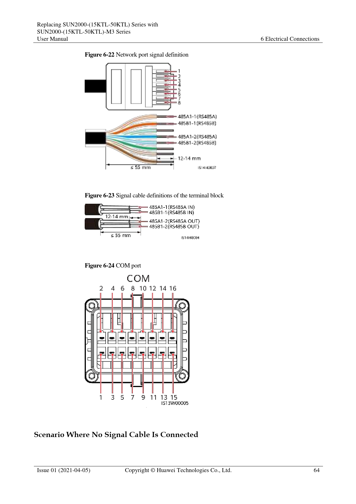
Replacing SUN2000-(15KTL-50KTL) Series with SUN2000-(15KTL-50KTL)-M3 Series User Manual
Figure 6-22 Network port signal definition

6 Electrical Connections

Figure 6-23 Signal cable definitions of the terminal block Figure 6-24 COM port

Scenario Where No Signal Cable Is Connected

Issue 01 (2021-04-05)

Copyright � Huawei Technologies Co., Ltd.

64

Replacing SUN2000-(15KTL-50KTL) Series with SUN2000-(15KTL-50KTL)-M3 Series User Manual

6 Electrical Connections

If no signal cable is connected to the SUN2000, use a waterproof plug to block the cable hole of the signal cable connector and connect the signal cable connector to the communications port on the SUN2000 to improve the waterproof performance.
Figure 6-25 Connecting the signal cable connector

6.3.2.1 Communication Modes
RS485 Communication
Figure 6-26 SmartLogger networking

It is recommended that the number of SUN2000s connected to each RS485 route be less than 30.

Issue 01 (2021-04-05)

Copyright � Huawei Technologies Co., Ltd.

65

Replacing SUN2000-(15KTL-50KTL) Series with SUN2000-(15KTL-50KTL)-M3 Series User Manual

6 Electrical Connections

MBUS communication
The MBUS is a communication mode in which communication signals are loaded to power cables through the communications board for transmission.

The built-in MBUS module in the SUN2000 does not need to be connected to cables.
6.3.2.2 (Optional) Connecting the RS485 Communications Cable to the SUN2000
Prerequisites
If the signal cables are long enough to connect to the communications port on the SUN2000, you do not need to install an AC adapter box.
Procedure
Step 1 If the original signal cable is connected through RJ45 network ports, cut off the RJ45 connectors.
Figure 6-27 Cut off the RJ45 connectors

Step 2 Connect the signal cable to the signal cable connector.

Issue 01 (2021-04-05)

Copyright � Huawei Technologies Co., Ltd.

66

Replacing SUN2000-(15KTL-50KTL) Series with SUN2000-(15KTL-50KTL)-M3 Series User Manual
Figure 6-28 Connecting the cable

6 Electrical Connections

Step 3 Connect the signal cable connector to the COM port. Figure 6-29 Securing the signal cable connector

----End
6.3.2.3 (Optional) Connecting the Signal Transfer Cable
Prerequisites
If the signal cables are not long enough to connect to the inverter communications port, connect a signal transfer cable.

Issue 01 (2021-04-05)

Copyright � Huawei Technologies Co., Ltd.

67

Replacing SUN2000-(15KTL-50KTL) Series with SUN2000-(15KTL-50KTL)-M3 Series User Manual
Figure 6-30 Terminal block in the AC adapter box

6 Electrical Connections

1Inverter

2Customer

Table 6-1 Signal definitions of the terminal block in the AC adapter box

Port

Reser RS485-1

ved

RS485-2 Ripple Control

Inverter -

A1-1

A1-2

A2

DIN1 DIN3

-

B1-1

B1-2

B2

DIN2 DIN4

Customer -

B-IN

B-OUT B2

DIN2 DIN4

-

A-IN

A-OUT A2

DIN1 DIN3

GND GND

Issue 01 (2021-04-05)

Copyright � Huawei Technologies Co., Ltd.

68

Replacing SUN2000-(15KTL-50KTL) Series with SUN2000-(15KTL-50KTL)-M3 Series User Manual
Figure 6-31 Pin definitions

6 Electrical Connections

Pin

Definition

1

485A1_1

3

485B1_1

5

-

7

485A2

9

485B2

11

-

13

-

15

-

Function

Pin

RS485 differential signal 2 +

RS485 differential signal 4 �

-

6

RS485 differential signal 8 +

RS485 differential signal 10 �

-

12

-

14

-

16

Definition 485A1_2
485B1_2
DIN1
DIN2
DIN3 DIN4 GND

Function
RS485 differential signal +
RS485 differential signal �
-
Dry contact for power grid scheduling

Procedure
Step 1 Remove the two security Torx screws from the maintenance compartment door using a security Torx wrench.

Issue 01 (2021-04-05)

Copyright � Huawei Technologies Co., Ltd.

69

Replacing SUN2000-(15KTL-50KTL) Series with SUN2000-(15KTL-50KTL)-M3 Series User Manual
Figure 6-32 Opening the AC adapter box

6 Electrical Connections

Step 2 Route the signal conversion cable and user-side signal cable through the COM port at the bottom of the AC adapter box.
Figure 6-33 Routing the signal cable

Step 3 Connect one end of the signal conversion cable to the COM port of the inverter.

Issue 01 (2021-04-05)

Copyright � Huawei Technologies Co., Ltd.

70

Replacing SUN2000-(15KTL-50KTL) Series with SUN2000-(15KTL-50KTL)-M3 Series User Manual
Figure 6-34 Connecting the signal conversion cable

6 Electrical Connections

Step 4 Connect the other end of the signal conversion cable to the terminal block. Figure 6-35 Connecting the signal conversion cable

Step 5 Connect the user-side signal cable to the terminal block. Figure 6-36 Connecting the user-side signal cable

Step 6 Secure the terminal block in the AC adapter box, and connect the PE wires of the signal conversion cable and the user-side signal cable.

Issue 01 (2021-04-05)

Copyright � Huawei Technologies Co., Ltd.

71

Replacing SUN2000-(15KTL-50KTL) Series with SUN2000-(15KTL-50KTL)-M3 Series User Manual
Figure 6-37 Secure the terminal block

6 Electrical Connections

----End

6.3.3 Installing the AC Output Power Cable

Precautions

An AC switch must be installed on the AC side of the SUN2000 to ensure that the SUN2000 can be safely disconnected from the power grid.

Do not connect loads between the SUN2000 and the AC switch.

 Use a socket wrench and extension rod to connect the AC power cable. The extension rod must be longer than 150 mm.
 Do not install third-party devices in the AC connection box.
There are two rows of AC terminals in the AC adapter box. The lower row is used to connect the AC transfer cable between the AC adapter box and the SUN2000, and the upper row is used to connect the AC output power cable on the user side.
Procedure
Step 1 Connect the AC transfer cable to the AC terminals in the lower row of the AC adapter box.

Issue 01 (2021-04-05)

Copyright � Huawei Technologies Co., Ltd.

72

Replacing SUN2000-(15KTL-50KTL) Series with SUN2000-(15KTL-50KTL)-M3 Series User Manual
Figure 6-38 Connecting the AC transfer cable

6 Electrical Connections

Step 2 Remove the AC terminal box and install partition boards. Figure 6-39 Removing the AC terminal box
Step 3 Route the AC transfer cable through the AC wiring terminal.

Issue 01 (2021-04-05)

Copyright � Huawei Technologies Co., Ltd.

73

Replacing SUN2000-(15KTL-50KTL) Series with SUN2000-(15KTL-50KTL)-M3 Series User Manual
Figure 6-40 Routing the AC power cable

6 Electrical Connections

Step 4 Connect the AC transfer cable to the SUN2000. Figure 6-41 Connecting the AC transfer cable

Step 5 Select an appropriate rubber liner based on the cable outer diameter.

Issue 01 (2021-04-05)

Copyright � Huawei Technologies Co., Ltd.

74

Replacing SUN2000-(15KTL-50KTL) Series with SUN2000-(15KTL-50KTL)-M3 Series User Manual
Figure 6-42 Selecting an appropriate rubber liner

6 Electrical Connections

Step 6 Connect the AC output power cable on the user side (using a five-core cable as an example). Figure 6-43 Connecting the AC power cable

Step 7 Install the AC terminal cover and close the door of the adapter box.

Issue 01 (2021-04-05)

Copyright � Huawei Technologies Co., Ltd.

75

Replacing SUN2000-(15KTL-50KTL) Series with SUN2000-(15KTL-50KTL)-M3 Series User Manual
Figure 6-44 Installing the AC terminal cover

6 Electrical Connections

----End
6.3.4 Installing DC Input Power Cables
Precautions
 Before connecting the DC input power cables, ensure that the DC voltage is within the safe range (lower than 60 V DC) and that the DC switch on the SUN2000 is OFF. Failing to do so may result in electric shocks.
 When the SUN2000 is running, it is not allowed to work on the DC input power cables, such as connecting or disconnecting a PV string or a PV module in a PV string. Failing to do so may cause electric shocks.
 If no PV string connects to a DC input terminal of the SUN2000, do not remove the watertight cap from the DC input terminals. Otherwise, the IP rating of the SUN2000 will be affected.
Ensure that the following conditions are met. Otherwise, the SUN2000 may be damaged, or even a fire may occur.

Issue 01 (2021-04-05)

Copyright � Huawei Technologies Co., Ltd.

76

Replacing SUN2000-(15KTL-50KTL) Series with SUN2000-(15KTL-50KTL)-M3 Series User Manual

6 Electrical Connections

 PV modules connected in series in each PV string are of the same specifications.
 The DC input voltage of the SUN2000 shall not exceed 1100 V DC under any circumstance.
 The polarities of electric connections are correct on the DC input side. The positive and negative terminals of a PV string connect to the corresponding positive and negative DC input terminals of the SUN2000, respectively.
 If the DC input power cables are reversely connected, do not operate the DC switch as well as positive and negative connectors immediately. Wait until the solar irradiance declines at night and the PV string current reduces to below 0.5 A, and then turn off the DC switch and remove the positive and negative connectors. Correct the PV string polarity before reconnecting the PV string to the SUN2000.

 The SUN2000 does not support power supplies other than PV strings. Since the output of the PV string connected to the SUN2000 cannot be grounded, ensure that the PV module output is well insulated to ground.
 During the installation of PV strings and the SUN2000, the positive or negative terminals of PV strings may be short-circuited to ground if the power cables are not properly installed or routed. In this case, an AC or DC short circuit may occur and damage the SUN2000. The caused device damage is not covered under any warranty.
 In the spare part replacement scenario, the DC input power cables can be connected only to PV1�PV6. If the DC input power cables are connected to PV7 or PV8, the inverter data cannot be transmitted to the northbound device.
Figure 6-45 DC input terminals

When the DC input is not fully configured, the DC input terminals must meet the following requirements:

1. Evenly distribute the DC input power cables on the four MPPTs and preferentially connect them from MPPT 1 to MPPT 4.
2. Maximize the number of connected MPPTs.

Number of PV Strings

Terminal Selection

Number of PV Strings

Terminal Selection

1

Connects to any route.

2

PV1, PV7

3

PV1, PV3, PV7

4

PV1, PV3, PV5, PV7

5

PV1, PV2, PV3, PV5, PV7 6

PV1, PV2, PV3, PV5, PV7,

PV8

Issue 01 (2021-04-05)

Copyright � Huawei Technologies Co., Ltd.

77

Replacing SUN2000-(15KTL-50KTL) Series with SUN2000-(15KTL-50KTL)-M3 Series User Manual

6 Electrical Connections

Number of PV Strings
7

Terminal Selection
PV1, PV2, PV3, PV4, PV5, PV7, PV8

Number of PV Strings
8

Terminal Selection
PV1, PV2, PV3, PV4, PV5, PV6, PV7, PV8

Procedure

 Before connecting DC input power cables, ensure that the original DC terminals have been cut off. If the original DC connector is directly connected to the SUN2000-(15KTL-50KTL)-M3 series, the inverter may be burnt.
 You are advised to use the PV-CZM-22100 (Staubli) crimping tool and do not use it with the positioning block. Otherwise, the metal terminals may be damaged.
 The PV-MS (Staubli) or PV-MS-HZ (Staubli) open-end wrench is recommended.
 Cables with high rigidity, such as armored cables, are not recommended as DC input power cables, because poor contact may be caused by the bending of the cables.
 Before assembling DC connectors, label the cable polarities correctly to ensure correct cable connections.
 After the positive and negative connectors snap into place, pull the DC input power cables back to ensure that they are connected securely.

Use the positive and negative Staubli MC4 metal terminals and DC connectors delivered with the SUN2000. Using incompatible positive and negative metal terminals and DC connectors may result in serious consequences. The caused device damage is not covered under any warranty or service agreement.
Step 1 Cut off the original DC terminals.
Figure 6-46 Cut off the original DC terminals

Step 2 Connect the DC power cables.

Issue 01 (2021-04-05)

Copyright � Huawei Technologies Co., Ltd.

78

Replacing SUN2000-(15KTL-50KTL) Series with SUN2000-(15KTL-50KTL)-M3 Series User Manual
Figure 6-47 Connecting DC power cables

6 Electrical Connections

If the original DC input power cables are not long enough, use the DC input extension cables delivered with the package.
Figure 6-48 Connecting the DC input extension cable

----End

6.3.5 (Optional) Installing the WLAN-FE Smart Dongle

Procedure

If the original SUN2000 uses the FE communication mode, you need to install the WLAN-FE Smart Dongle for the SUN2000 connected to the monitoring device after the replacement. Use the RS485 communication mode for other SUN2000s.

Issue 01 (2021-04-05)

Copyright � Huawei Technologies Co., Ltd.

79

Replacing SUN2000-(15KTL-50KTL) Series with SUN2000-(15KTL-50KTL)-M3 Series User Manual
Figure 6-49 Networking diagram before the replacement

6 Electrical Connections

Figure 6-50 Networking diagram after the replacement
Step 1 Install the WLAN-FE Smart Dongle. Figure 6-51 Installing the WLAN-FE Smart Dongle

 The WLAN-FE Smart Dongle is not provided in standard configuration.  Install the network cable before installing the Smart Dongle on the SUN2000.

Issue 01 (2021-04-05)

Copyright � Huawei Technologies Co., Ltd.

80

Replacing SUN2000-(15KTL-50KTL) Series with SUN2000-(15KTL-50KTL)-M3 Series User Manual

6 Electrical Connections

For details about how to use the WLAN-FE Smart Dongle SDongleA-05, see SDongleA-05 Quick Guide (WLAN-FE). The quick guide is delivered with the Smart Dongle. You can also scan the QR code to obtain the documentation.

----End

Issue 01 (2021-04-05)

Copyright � Huawei Technologies Co., Ltd.

81

Replacing SUN2000-(15KTL-50KTL) Series with SUN2000-(15KTL-50KTL)-M3 Series User Manual

7 Commissioning

7 Commissioning

7.1 Checking Before Power-On

Table 7-1 Checklist

No.

Check Item

1

SUN2000 installation

2

Smart Dongle

3

Cable routing

4

Cable ties

5

Reliable grounding

6

Switch

7

Cable connection

8

Unused terminals and ports

9

Installation environment

Acceptance Criteria
The SUN2000 is installed correctly and securely.
The Smart Dongle is installed correctly and securely.
The cables are routed properly as required by the customer.
Cable ties are evenly distributed and no burr exists.
The PE cable is connected correctly and securely.
DC switches and all the switches connecting to the SUN2000 are OFF.
The AC output power cable, and DC input power cables are connected correctly and securely.
Unused terminals and ports are locked by watertight caps.
The installation space is proper, and the installation environment is clean and tidy.

Issue 01 (2021-04-05)

Copyright � Huawei Technologies Co., Ltd.

82

Replacing SUN2000-(15KTL-50KTL) Series with SUN2000-(15KTL-50KTL)-M3 Series User Manual
7.2 System Power-On
Prerequisites

7 Commissioning

 Before turning on the AC switch between the SUN2000 and the power grid, check that the AC voltage is within the specified range using a multimeter.
 If the DC power supply is connected but the AC power supply is disconnected, the SUN2000 will report a Grid Loss alarm. The SUN2000 can start properly only after the power grid recovers.
Procedure
Step 1 Turn on the AC switch between the SUN2000 and the power grid. Step 2 (Optional) Remove the locking screw beside the DC switch.
Figure 7-1 Removing the locking screw beside the DC switch

Step 3 Turn on the DC switch at the bottom of the SUN2000. Step 4 Observe the LED indicators to check the operating status of the SUN2000.

Table 7-2 Indicator description

Category

Status

Description

Running indicator LED1

LED2

�

Steady green

Steady green

The SUN2000 is operating in grid-tied mode.

Blinking green

Off

slowly (on for 1s and

off for 1s)

The DC is on and the AC is off.

Blinking green slowly (on for 1s and off for 1s)

Blinking green slowly (on for 1s and off for 1s)

Both the DC and AC are on, and the SUN2000 is not supplying power to the power grid.

Issue 01 (2021-04-05)

Copyright � Huawei Technologies Co., Ltd.

83

Replacing SUN2000-(15KTL-50KTL) Series with SUN2000-(15KTL-50KTL)-M3 Series User Manual

7 Commissioning

Category

Status

Description

Off

Blinking green

The DC is off and the

slowly

AC is on.

Off

Off

Both the DC and AC

are off.

Blinking red fast (on � for 0.2s and off for 0.2s)

DC environment alarm

�

Blinking red fast (on AC environment

for 0.2s and off for alarm

0.2s)

Steady red

Steady red

Faulty

Communications indicator

LED3
Blinking green fast (on for 0.2s and then off for 0.2s)

�
Communication is in progress.

Blinking green slowly (on for 1s and off for A mobile phone is

1s)

connected.

Off

No communication

Note: If LED1, LED2, and LED3 are steady red, the SUN2000 is faulty and needs to be replaced.

----End

Issue 01 (2021-04-05)

Copyright � Huawei Technologies Co., Ltd.

84

Replacing SUN2000-(15KTL-50KTL) Series with SUN2000-(15KTL-50KTL)-M3 Series User Manual

8 Human-Machine Interaction

8 Human-Machine Interaction
8.1 Setting Parameters for Replacing a SUN2000
Access the HUAWEI AppGallery (http://appstore.huawei.com), search for SUN2000, and download the app installation package. You can also scan the QR code below to download the app. You are advised to use a browser to scan the QR code.

 The screenshots are for reference only. The actual screens may vary.  Obtain the initial password for connecting to the SUN2000 WLAN from the label on the
side of the SUN2000.  Set the password upon the first login. You are advised to change the password periodically.
After changing the password, remember the new password to ensure account security. Not changing the initial password may cause password disclosure. A password left unchanged for a long period of time may be stolen or cracked. If a password is lost, devices cannot be accessed. In these cases, the user is liable for any loss caused to the PV plant.  Set the correct grid code based on the application area and scenario of the SUN2000.
Step 1 Connect to the WLAN of the SUN2000 and log in as user installer.

Issue 01 (2021-04-05)

Copyright � Huawei Technologies Co., Ltd.

85

Replacing SUN2000-(15KTL-50KTL) Series with SUN2000-(15KTL-50KTL)-M3 Series User Manual
Figure 8-1 Login

8 Human-Machine Interaction

At the first login, the Quick settings screen is displayed by default. Exit the quick settings.
Step 2 Choose Maintenance > Device replacement, select a device replacement type, and set related parameters.
Figure 8-2 Replacement

You need to set Device replacement parameter only when the SUN2000 V100, SUN2000 V200R001, or SUN2000 V200R002 inverters are replaced with SUN2000-(15KTL-50KTL)-M3 series inverters. You do not need to set the parameter when the inverters are replaced with inverters of the same version.
Step 3 (Optional) If other parameters need to be set, tap Settings on the home screen and set other parameters. ----End

Issue 01 (2021-04-05)

Copyright � Huawei Technologies Co., Ltd.

86

Replacing SUN2000-(15KTL-50KTL) Series with SUN2000-(15KTL-50KTL)-M3 Series User Manual

8 Human-Machine Interaction

8.2 SmartLogger Networking Scenario
For details, see PV Plants Connecting to Huawei Hosting Cloud Quick Guide (Inverters + SmartLogger3000), PV Plants Connecting to SmartPVMS Quick Guide (Inverters + SmartLogger3000 + RS485 Networking) and PV Plants Connecting to SmartPVMS Quick Guide (Inverters + SmartLogger3000 + MBUS Networking).

Issue 01 (2021-04-05)

Copyright � Huawei Technologies Co., Ltd.

87

Replacing SUN2000-(15KTL-50KTL) Series with SUN2000-(15KTL-50KTL)-M3 Series User Manual

9 Maintenance

9.1 System Power-Off
Precautions

9 Maintenance

After the SUN2000 powers off, the remaining electricity and heat may still cause electric shocks and body burns. Therefore, put on protective gloves and begin operating the SUN2000 five minutes after the power-off.
Procedure
Step 1 Send a shutdown command on the app. Step 2 Turn off the AC switch between the SUN2000 and the power grid. Step 3 Turn off the DC switch at the bottom of the SUN2000. Step 4 (Optional) Install the locking screw for the DC switch.
Figure 9-1 Installing the locking screw for the DC switch

Step 5 Turn on the DC switch between the PV string and the SUN2000 if there is any. ----End

Issue 01 (2021-04-05)

Copyright � Huawei Technologies Co., Ltd.

88

Replacing SUN2000-(15KTL-50KTL) Series with SUN2000-(15KTL-50KTL)-M3 Series User Manual

9 Maintenance

9.2 Routine Maintenance
To ensure that the SUN2000 can operate properly for a long term, you are advised to perform routine maintenance on it as described in this chapter.

Before cleaning the system, connecting cables, and ensuring the grounding reliability, power off the system.

Table 9-1 Maintenance checklist

Check Item

Check Method

Maintenance Interval

System cleanliness

Check periodically that the heat sinks are free from obstacles and dust.

Once every 6 to 12 months

System operating  Check that the SUN2000 is not damaged

status

or deformed.

 Check that the SUN2000 operates with no abnormal sound.

 Check that all SUN2000 parameters are correctly set during operation.

Once every 6 months

Electrical connection

 Check that cables are secured.
 Check that cables are intact, and that in particular, the parts touching the metallic surface are not scratched.

The first inspection is 6 months after the initial commissioning. From then on, the interval can be 6 to 12 months.

Grounding reliability

Check that ground cables are securely connected.

The first inspection is 6 months after the initial commissioning. From then on, the interval can be 6 to 12 months.

Air tightness

Check that all terminals and ports are properly sealed.

Once a year

9.3 Troubleshooting
Alarm severities are defined as follows:
 Major: The inverter is faulty. As a result, the output power decreases or the grid-tied power generation is stopped.
 Minor: Some components are faulty without affecting the grid-tied power generation.  Warning: The inverter works properly. The output power decreases or some authorization
functions fail due to external factors.

Issue 01 (2021-04-05)

Copyright � Huawei Technologies Co., Ltd.

89

Replacing SUN2000-(15KTL-50KTL) Series with SUN2000-(15KTL-50KTL)-M3 Series User Manual

9 Maintenance

Table 9-2 Common fault alarm list

ID

Name Severity Cause

Solution

103
106~113 120~127

High DC input voltage

Major

Abnormal string 1 to Abnormal string 8

Warning

String 1 reversed to String 8 reversed

 Cause ID = 1: Major
 Cause ID = 2: Warni ng

The PV array is not properly configured. Excessive PV modules are connected in series to the PV string, and therefore the PV string open-circuit voltage exceeds the maximum inverter operating voltage.  Cause ID 1: PV strings 1
and 2  Cause ID 2: PV strings 3
and 4  Cause ID 3: PV strings 5
and 6  Cause ID 4: PV strings 7
and 8
Cause ID = 1  The PV string is shaded for
a long time.  The PV string is aged.
 Cause ID = 1 The PV string polarity is reversed.
 Cause ID = 2 The number of PV modules connected in series to the PV string is insufficient. As a result, the terminal voltage is lower than that of other strings.

Reduce the number of PV modules connected in series to the PV string until the PV string open-circuit voltage is less than or equal to the maximum inverter operating voltage. After the PV string configuration is corrected, the alarm disappears.
1. Check whether the PV string current is obviously lower than the currents of other PV strings.
2. If the PV string current is obviously low, check whether the PV string is shaded.
3. If the PV string surface is clean and not shaded, check whether PV modules are damaged.
 Cause ID = 1 Check whether the PV string is reversely connected to the inverter. If yes, wait until the solar irradiance declines at night and the PV string current drops to below 0.5 A. Then, turn off the two DC switches and correct the PV string connection.
 Cause ID = 2 Check whether the number of PV modules connected in series to the PV string is less than that of other PV strings. If yes, adjust the number of PV modules.

200

Abnormal Major

Abnormal external conditions  Cause ID = 3/10/11

DC circuit

trigger the protection for the DC circuit inside the inverter. The possible causes are as follows:

1. The inverter monitors its external operating conditions in real time and automatically recovers after the fault is

 Cause ID = 3

rectified.

Issue 01 (2021-04-05)

Copyright � Huawei Technologies Co., Ltd.

90

Replacing SUN2000-(15KTL-50KTL) Series with SUN2000-(15KTL-50KTL)-M3 Series User Manual

9 Maintenance

ID

Name Severity Cause

Solution

The inverter input is

2. If the alarm persists, contact

disconnected accidentally,

Huawei technical support.

or the PV string output power changes sharply because the PV string is shaded.
 Cause ID = 10

 Cause ID = 12/15
Turn off the AC output switch and DC input switch, and then turn them on after 5 minutes. If the alarm persists, contact

The three phases of the

Huawei technical support.

power grid are seriously unbalanced, which triggers the protection for the internal control circuit of

NOTE
Cause ID = 12: Perform the preceding operations when the PV string current is less than 1 A.

the inverter.

 Cause ID = 16

 Cause ID = 11

1. If there is no PID module in

The power grid voltage

the system, set PID

changes sharply and the

protection at night and

inverter input power fails to

Night-time reactive power

discharge in a short time,

output to Disable for the

which increases the internal

inverter over the SmartLogger

voltage and triggers

or app.

protection.

2. If there is a PID module in the

 Cause ID = 12/15

system, check whether the

An unrecoverable fault occurs on a circuit inside

device is abnormal. If yes, rectify the fault.

the inverter.

3. Check whether PID

 Cause ID = 16
The voltage between the PV string and the ground is abnormal, and there is a risk of power degradation.

compensation direction of the inverter and PV module compensation voltage direction of the PID module are correctly set based on the PV module model. If not,

reset them on the

SmartLogger or app.

4. If the alarm persists, contact your dealer or Huawei technical support.

202

Abnormal Major

Abnormal external conditions  Cause ID = 13/14/16

invert circuit

trigger the protection for the inverter circuit inside the inverter. The possible causes are as follows:

1. The inverter monitors its external operating conditions in real time and automatically recovers after the fault is

 Cause ID = 13

rectified.

The power grid voltage drops dramatically or the power grid is short-circuited. As a result, the internal voltage detection circuit in the inverter is damaged.

2. If the alarm persists, contact Huawei technical support.
 Cause ID = 20
1. Check whether the inverter output power cable is short-circuited.

Issue 01 (2021-04-05)

Copyright � Huawei Technologies Co., Ltd.

91

Replacing SUN2000-(15KTL-50KTL) Series with SUN2000-(15KTL-50KTL)-M3 Series User Manual

9 Maintenance

ID

Name Severity Cause

Solution

 Cause ID = 14
The power grid voltage drops dramatically or the power grid is short-circuited. As a result, the inverter transient output current exceeds the upper threshold, and protection is triggered.

2. If the alarm persists, contact Huawei technical support.

 Cause ID = 16

The DC component in the power grid current exceeds the upper threshold.

 Cause ID = 20

The inverter output is short-circuited. As a result, the output current surges to a value above the upper threshold, and the inverter protection is triggered.

301

Abnormal Major

The power grid voltage is

 Cause ID = 4

grid voltage

outside the acceptable range. The possible causes are as follows:

1. If the alarm occurs occasionally, the power grid may be abnormal temporarily.

 Cause ID = 4

The inverter automatically

The power grid voltage is below the lower threshold.
 Cause ID = 16
The power grid voltage exceeds the upper threshold.

recovers after detecting that the power grid becomes normal.
2. If the alarm persists, check whether the power grid voltage is within the acceptable range. If not,

 Cause ID = 19

contact the local power

The power grid voltage has exceeded the upper threshold for 10 minutes.
 Cause ID = 26

operator. If yes, log in to the app, SmartLogger, or NMS to change the power grid overvoltage and undervoltage protection thresholds with the

The power grid voltage

consent of the local power

exceeds the upper

operator.

threshold.

3. If the alarm persists for a long

 Cause ID = 28

time, check the AC circuit

The three phases of the power grid differ greatly in

breaker and AC output power cable.

voltage.

 Cause ID = 16/19/26

 Cause ID = 29
1. Power grid outage occurs.
2. The AC circuit is

1. If the voltage at the grid connection point is too high, contact the local power operator.

Issue 01 (2021-04-05)

Copyright � Huawei Technologies Co., Ltd.

92

Replacing SUN2000-(15KTL-50KTL) Series with SUN2000-(15KTL-50KTL)-M3 Series User Manual

9 Maintenance

ID

Name Severity Cause

Solution

disconnected or the AC switch is off.
 Cause ID = 31/32/33
The impedance of the output phase wire A (cause ID = 31)/B (cause ID = 32)/C (cause ID = 33) to the PE cable is low or the wire is short-circuited.

2. If you have confirmed that the voltage at the grid connection point exceeds the upper threshold and obtained consent from the local power operator, modify the overvoltage protection thresholds.
3. Check whether the peak grid voltage exceeds the upper threshold.

 Cause ID = 28

1. If the exception is caused by an external fault, the inverter automatically recovers after the fault is rectified.

2. If the alarm persists and affects the energy yield of the PV plant, contact the local power operator.

 Cause ID = 29

1. Check the AC voltage.

2. Check whether the AC circuit is disconnected or the AC switch is off.

 Cause ID = 31/32/33

Check the impedance of the output phase wire A (cause ID = 31)/B (cause ID = 32)/C (cause ID = 33) to the PE cable, locate the position with lower impedance, resolve the issue.

305

Abnormal Major

 Cause ID = 2

 Cause ID = 2/4

grid frequency

The actual power grid frequency is higher than the

1. If the alarm occurs occasionally, the power grid

requirements for the local

may be abnormal temporarily.

power grid code.

The inverter automatically

 Cause ID = 4
The actual power grid frequency is lower than the requirements for the local power grid code.
 Cause ID = 5

recovers after detecting that the power grid becomes normal.
2. If the alarm persists, check whether the power grid frequency is within the acceptable range. If not,

The actual change rate of

contact the local power

the power grid frequency

operator. If yes, log in to the

does not meet the

app, SmartLogger, or NMS to

requirements for the local

change the power grid

power grid code.

overfrequency and

Issue 01 (2021-04-05)

Copyright � Huawei Technologies Co., Ltd.

93

Replacing SUN2000-(15KTL-50KTL) Series with SUN2000-(15KTL-50KTL)-M3 Series User Manual

9 Maintenance

ID

Name Severity Cause

Solution
underfrequency protection thresholds with the consent of the local power operator.
 Cause ID = 5
1. If the alarm occurs occasionally, the power grid may be abnormal temporarily. The inverter automatically recovers after detecting that the power grid becomes normal.
2. If the alarm persists, check whether the power grid frequency is within the acceptable range. If not, contact the local power operator.

313

Low

Major

Cause ID = 1

1. Check the impedance between the

insulation resistance

 The PV array is short-circuited with PE.

PV string and the PE cable. If a short circuit occurs, rectify the fault.

 The PV string is installed in 2. If you have confirmed that the

a moist environment for a

impedance is less than the default

long time.

value in a cloudy or rainy

environment, log in to the app,

SmartLogger, or NMS and set

Insulation resistance protection

threshold.

318

Abnormal Major

Cause ID = 1

1. If the alarm occurs accidentally,

residual current

The insulation resistance against the PE cable at the input side decreases when the inverter is operating, which

the external power cable may be abnormal temporarily. The inverter automatically recovers after the fault is rectified.

causes an excessively high

2. If the alarm persists or lasts a

residual current.

long time, check whether the impedance between the PV string

and ground is too low.

321

Cabinet Major

Cause ID = 1

1. Check the ventilation and

overtemp erature

 The inverter is installed in a place with poor ventilation.

ambient temperature at the inverter installation position.

 The ambient temperature

2. If the ventilation is poor or the ambient temperature exceeds the

exceeds the upper threshold.

upper threshold, improve the ventilation and heat dissipation.

 The internal fan is faulty. 3. If the ventilation and ambient

temperature are normal, contact

Huawei technical support.

326

Abnormal Major

Cause ID = 1

1. Check whether the neutral wire

grounding

 The neutral wire or PE

and PE cable of the inverter are properly connected.

Issue 01 (2021-04-05)

Copyright � Huawei Technologies Co., Ltd.

94

Replacing SUN2000-(15KTL-50KTL) Series with SUN2000-(15KTL-50KTL)-M3 Series User Manual

9 Maintenance

ID

Name Severity Cause

Solution

cable of the inverter is not connected.
 The output side of the inverter does not connect to an isolation transformer when the PV strings are grounded.

2. If the PV string output is grounded, check whether the output side of the inverter connects to an isolation transformer.

400

System Major

Cause ID = 1/3/21/23/27

Turn off the AC output switch and

fault

An unrecoverable fault occurs DC input switch, and then turn them

on a circuit inside the inverter. on after 5 minutes. If the alarm

persists, contact Huawei technical

support.

410

Abnormal Major

Cause ID = 4

1. When the alarm is generated, the

auxiliary power

The sampling control board has an abnormal voltage. The possible causes are as follows:

inverter shuts down automatically. After the fault is rectified, the inverter automatically starts.

 The internal power chip of 2. If the alarm persists, contact

the sampling control board is faulty.

Huawei technical support.

 The detection circuit is faulty.

411

AFCI

Major

Cause ID = 1/2/3

1. Turn off the AC output switch

self-check failure

The AFCI self-check fails.

and DC input switch, and then turn them on after 5 minutes. If

the alarm persists, contact

Huawei technical support.

2. If you have confirmed that the AFCI function is not required, disable it.

412

DC arc Major

Cause ID = 1/2/3/4

Check whether the PV string cable is

fault

The PV string cable is in poor in poor contact or with open circuits.

contact or with open circuits. If yes, reconnect the cable.

504

Software Minor

Cause ID = 1/2/3

Check whether you have performed a

version unmatch

During inverter software upgrade, the version of the software loaded is incorrect.

software upgrade recently. If yes, upgrade the software to the correct version again.

505

Upgrade Major

Cause ID = 1

Perform the upgrade again.

failed

The upgrade is not completed

normally.

506

License Warning Cause ID = 1

1. Apply for a new license.

expired

 The license has entered its 2. Load a new license.

grace period.

 The license is about to expire.

Issue 01 (2021-04-05)

Copyright � Huawei Technologies Co., Ltd.

95

Replacing SUN2000-(15KTL-50KTL) Series with SUN2000-(15KTL-50KTL)-M3 Series User Manual

9 Maintenance

ID 2001
2002
2003 2011 2012

Name High string input voltage
DC arc fault
DC arc fault String reverse connectio n
String current backfeed

Severity Major
Major
Major Major Warning

Cause

Solution

The PV array is not properly configured. Excessive PV modules are connected in series to the PV string, and therefore the PV string open-circuit voltage exceeds the maximum inverter operating voltage.
 Cause ID 1: PV strings 1 and 2
 Cause ID 2: PV strings 3 and 4
 Cause ID 3: PV strings 5 and 6
 Cause ID 4: PV strings 7 and 8

Reduce the number of PV modules connected in series to the PV string until the PV string open-circuit voltage is less than or equal to the maximum inverter operating voltage. After the PV string configuration is corrected, the alarm disappears.

The PV string power cables arc or are in poor contact.
 Cause ID 1: PV strings 1 and 2
 Cause ID 2: PV strings 3 and 4
 Cause ID 3: PV strings 5 and 6
 Cause ID 4: PV strings 7 and 8

Check whether the PV string cables arc or are in poor contact.

The PV string power cables arc Check whether the PV string cables

or are in poor contact.

arc or are in poor contact.

Cause ID 1�8: PV strings 1�8

The PV string polarity is reversed.
Cause ID 1�8: PV strings 1�8

Check whether the PV string is reversely connected to the inverter. If yes, wait until the solar irradiance declines at night and the PV string current drops to below 0.5 A. Then, turn off the two DC switches and correct the PV string connection.

The number of PV modules connected in series to the PV string is insufficient. As a result, the terminal voltage is lower than that of other strings.
Cause ID 1�8: PV strings 1�8

1. Check whether the number of PV modules connected in series to the PV string is less than that of other PV strings. If yes, wait until the PV string current drops below 0.5 A, turn off all DC switches, and adjust the number of PV modules in the PV string.
2. Check whether the open-circuit voltage of the PV string is abnormal.

Issue 01 (2021-04-05)

Copyright � Huawei Technologies Co., Ltd.

96

Replacing SUN2000-(15KTL-50KTL) Series with SUN2000-(15KTL-50KTL)-M3 Series User Manual

9 Maintenance

ID 2013 2014
2021 2031

Name Severity
Abnormal Warning string power

High input string voltage to ground

Major

AFCI

Major

self-check

failure

Phase

Major

wire

short-circ

Cause  The PV string is shaded for
a long time.  The PV string is aged
abnormally. Cause ID 1�8: PV strings 1�8
Cause ID = 1 The voltage between the input PV modules and the ground is abnormal, and there is a risk of power degradation.
Cause ID = 1, 2 The AFCI self-check fails. Cause ID = 1 The impedance of the output

Solution
3. Check whether the PV string is shaded.
1. Check whether the current of the abnormal PV string is lower than that of other PV strings. If yes, check whether the abnormal PV string is shaded and the actual number of PV modules in the PV string is the same as the configured number.
2. If the abnormal PV string is clean and not shaded, check whether the PV string is damaged.
1. If no PID compensation device exists in the system, disable the PID protection function at night. Note: If the PID protection function is disabled but reactive power compensation at night is enabled, PV modules may be degraded.
2. If the system has a PID compensation device, check whether the device is abnormal. If yes, rectify the fault.
3. Check whether the settings of compensation direction for the inverter and the PID compensation device are consistent. If not, set them to be consistent based on the PV module model. (Note: If the PV� is set to positive offset, the voltage between the inverter PV� and the ground should be greater than 0 V to clear the alarm; if the PV+ is set to negative offset, the voltage between the inverter PV+ and the ground should be less than 0 V to clear the alarm.)
4. If the alarm persists, contact your dealer or Huawei technical support.
Turn off the AC output switch and DC input switch, and then turn them on after 5 minutes. If the alarm persists, contact Huawei technical support.
Check the impedance of the output phase wire to PE, locate the position with low impedance, and rectify the

Issue 01 (2021-04-05)

Copyright � Huawei Technologies Co., Ltd.

97

Replacing SUN2000-(15KTL-50KTL) Series with SUN2000-(15KTL-50KTL)-M3 Series User Manual

9 Maintenance

ID 2032 2033
2034
2035

Name uited to PE Grid loss
Grid undervolt age
Grid overvolta ge
Grid volt. Imbalanc

Severity Major Major
Major
Major

Cause phase wire to PE is low or the output phase wire is short-circuited to PE. Cause ID = 1  Power grid outage occurs.  The AC circuit is
disconnected or the AC switch is off. Cause ID = 1 The power grid voltage is below the lower threshold or the low-voltage duration has lasted for more than the value specified by LVRT.
Cause ID = 1 The power grid voltage exceeds the upper threshold or the high voltage duration has lasted for more than the value specified by HVRT.
Cause ID = 1

Solution
fault.
1. The alarm is cleared automatically after the power grid recovers.
2. Check whether the AC circuit is disconnected or the AC switch is off.
1. If the alarm occurs occasionally, the power grid may be abnormal temporarily. The inverter automatically recovers after detecting that the power grid becomes normal.
2. If the alarm persists, check whether the power grid voltage is within the acceptable range. If not, contact the local power operator. If yes, modify the grid undervoltage protection threshold through the app, SmartLogger, or NMS with the consent of the local power operator.
3. If the alarm persists for a long time, check the AC circuit breaker and AC output power cable.
1. If the alarm occurs occasionally, the power grid may be abnormal temporarily. The inverter automatically recovers after detecting that the power grid becomes normal.
2. If the alarm persists, check whether the power grid frequency is within the acceptable range. If not, contact the local power operator. If yes, modify the grid overfrequency protection threshold through the app, SmartLogger, or NMS with the consent of the local power operator.
3. Check whether the peak voltage of the power grid is too high. If the alarm persists and lasts for a long time, contact the local power operator.
1. If the alarm occurs occasionally, the power grid may be abnormal

Issue 01 (2021-04-05)

Copyright � Huawei Technologies Co., Ltd.

98

Replacing SUN2000-(15KTL-50KTL) Series with SUN2000-(15KTL-50KTL)-M3 Series User Manual

9 Maintenance

ID 2036 2037 2038

Name e
Grid overfrequ ency
Grid underfreq uency
Unstable grid

Severity Major Major Major

Cause The difference between power grid phase voltages exceeds the upper threshold.
Cause ID = 1 Power grid exception: The actual power grid frequency is higher than the requirements for the local power grid code.
Cause ID = 1 Power grid exception: The actual power grid frequency is lower than the requirements for the local power grid code.
Cause ID = 1 Power grid exception: The

Solution
temporarily. The inverter automatically recovers after detecting that the power grid becomes normal.
2. If the alarm persists, check whether the power grid voltage is within the acceptable range. If not, contact the local power operator.
3. If the alarm lasts for a long time, check the AC output power cable connection.
4. If the AC output power cable is correctly connected, yet the alarm persists and affects the energy yield of the PV plant, contact the local power operator.
1. If the alarm occurs occasionally, the power grid may be abnormal temporarily. The inverter automatically recovers after detecting that the power grid becomes normal.
2. If the alarm persists, check whether the power grid frequency is within the acceptable range. If not, contact the local power operator. If yes, modify the grid overfrequency protection threshold through the app, SmartLogger, or NMS with the consent of the local power operator.
1. If the alarm occurs occasionally, the power grid may be abnormal temporarily. The inverter automatically recovers after detecting that the power grid becomes normal.
2. If the alarm persists, check whether the power grid frequency is within the acceptable range. If not, contact the local power operator. If yes, modify the grid underfrequency protection threshold through the app, SmartLogger, or NMS with the consent of the local power operator.
1. If the alarm occurs occasionally, the power grid may be abnormal

Issue 01 (2021-04-05)

Copyright � Huawei Technologies Co., Ltd.

99

Replacing SUN2000-(15KTL-50KTL) Series with SUN2000-(15KTL-50KTL)-M3 Series User Manual

9 Maintenance

ID 2039 2040 2051 2061

Name Severity frequency

Output Major overcurre nt

Output DC compone nt overhigh

Major

Abnormal Major residual current

Abnormal Major grounding

Cause
actual change rate of the power grid frequency does not meet the requirements for the local power grid code.

Solution
temporarily. The inverter automatically recovers after detecting that the power grid becomes normal.
2. If the alarm persists, check whether the power grid frequency is within the acceptable range. If not, contact the local power operator.

Cause ID = 1
The power grid voltage drops dramatically or the power grid is short-circuited. As a result, the inverter transient output current exceeds the upper threshold, and protection is triggered.

1. The inverter monitors its external operating conditions in real time and automatically recovers after the fault is rectified.
2. If the alarm persists and affects the energy yield of the PV plant, check whether the output is short-circuited. If the fault cannot be rectified, contact your dealer or Huawei technical support.

Cause ID = 1 The DC component of the inverter output current exceeds the upper threshold.
Cause ID = 1 The insulation impedance of the input side to PE decreases when the inverter is operating.

1. The inverter monitors its external operating conditions in real time and automatically recovers after the fault is rectified.
2. If the alarm persists and affects the energy yield of the PV plant, contact your dealer or Huawei technical support.
1. If the alarm occurs accidentally, the external power cable may be abnormal temporarily. The inverter automatically recovers after the fault is rectified.
2. If the alarm persists or lasts a long time, check whether the impedance between the PV string and ground is too low.

Cause ID = 1
 The neutral wire or PE cable of the inverter is not connected.
 The output mode set for the inverter is inconsistent with the cable connection mode.

Power off the inverter (turn off the AC output switch and DC input switch, and wait for a period of time. For details about the wait time, see the description on the device safety warning label), and then perform the following operations:
1. Check whether the PE cable for the inverter is connected properly.
2. If the inverter is connected to a TN power grid, check whether the neutral wire is properly connected and whether the voltage of the neutral wire to

Issue 01 (2021-04-05)

Copyright � Huawei Technologies Co., Ltd.

100

Replacing SUN2000-(15KTL-50KTL) Series with SUN2000-(15KTL-50KTL)-M3 Series User Manual

9 Maintenance

ID 2062
2063
2064 2065 2066

Name
Low insulation resistance
Cabinet overtemp erature
Device fault
Upgrade failed or version mismatch License expired

Severity Major
Minor
Major Minor Warning

Cause

Solution
ground is normal.
3. After the inverter is powered on, check whether the output mode set for the inverter is consistent with the output cable connection mode.

Cause ID = 1
 The PV array is short-circuited with PE.
 The PV string has been in a moist environment for a long time and the circuit is not well insulated to ground.

1. Check the impedance between the PV string and the PE cable. If a short circuit occurs, rectify the fault.
2. Check whether the PE cable of the inverter is correctly connected.
3. If you have confirmed that the impedance is lower than the specified protection threshold in a cloudy or rainy environment, log in to the app, SmartLogger, or NMS and set Insulation resistance protection threshold.

Cause ID = 1
 The inverter is installed in a place with poor ventilation.
 The ambient temperature exceeds the upper threshold.
 The inverter is not operating properly.

1. Check the ventilation and ambient temperature at the inverter installation position.
2. If the ventilation is poor or the ambient temperature exceeds the upper threshold, improve the ventilation and heat dissipation.
3. If both the ventilation and ambient temperature meet requirements yet the alarm persists, contact your dealer or Huawei technical support.

Cause ID = 1�15
An unrecoverable fault occurs on a circuit inside the inverter.

Turn off the AC output switch and DC input switch, and then turn them on after 5 minutes. If the alarm persists, contact your dealer or Huawei technical support.

NOTICE
Cause ID = 1: Perform the preceding operations when the PV string current is less than 1 A.

Cause ID = 1�6
The upgrade is not completed normally.

1. Perform an upgrade again.
2. If the upgrade fails several times, contact your dealer or Huawei technical support.

Cause ID = 1  The privilege license has
entered the grace period.
 The privilege feature is

1. Apply for a new license. 2. Load a new certificate.

Issue 01 (2021-04-05)

Copyright � Huawei Technologies Co., Ltd.

101

Replacing SUN2000-(15KTL-50KTL) Series with SUN2000-(15KTL-50KTL)-M3 Series User Manual

9 Maintenance

ID 61440 2072 2085
2087

Name

Severity Cause about to expire.

Solution

Faulty

Minor

monitorin

g unit

Transient AC overvolta ge

Major

Built-in PID operation abnormal

Minor

Cause ID = 1
 The flash memory is insufficient.
 The flash memory has bad sectors.

Turn off the AC output switch and DC input switch, and then turn them on after 5 minutes. If the alarm persists, replace the monitoring board or contact your dealer or Huawei technical support.

Cause ID = 1
The inverter detects that the phase voltage exceeds the transient AC overvoltage protection threshold.

1. If the voltage at the grid connection point is too high, contact the local power operator.
2. If you have confirmed that the voltage at the grid connection point exceeds the upper threshold and obtained consent from the local power operator, modify the overvoltage protection thresholds.
3. Check whether the peak grid voltage exceeds the upper threshold.

Cause ID = 1, 2
 The output resistance of PV arrays to ground is low.
 The system insulation resistance is low.

 Cause ID = 1
1. Turn off the AC output switch and DC input switch, wait for a period of time (for details about the wait time, see the description on the device safety warning label), and then turn on the DC input switch and AC output switch.
2. If the alarm persists, contact your dealer or Huawei technical support.
 Cause ID = 2
1. Check the impedance between the PV array output and the ground. If a short circuit occurs or the insulation is insufficient, rectify the fault.
2. If the alarm persists, contact your dealer or Huawei technical support.

Internal Major fan abnormal

Cause ID = 1�4
The internal fan is short-circuited, the power supply is insufficient, or the fan is damaged.

Turn off the AC output switch and DC input switch, and then turn them on after 5 minutes. Wait for the inverter to connect to the power grid. If the alarm persists after 5 minutes, contact your dealer or Huawei technical support.

Issue 01 (2021-04-05)

Copyright � Huawei Technologies Co., Ltd.

102

Replacing SUN2000-(15KTL-50KTL) Series with SUN2000-(15KTL-50KTL)-M3 Series User Manual

9 Maintenance

Contact your dealer or Huawei technical support if all troubleshooting procedures listed above are completed and the fault still exists.

Issue 01 (2021-04-05)

Copyright � Huawei Technologies Co., Ltd.

103

Replacing SUN2000-(15KTL-50KTL) Series with SUN2000-(15KTL-50KTL)-M3 Series User Manual

10 Handling the Inverter

10 Handling the Inverter
10.1 Removing the SUN2000
Before removing the SUN2000, disconnect both AC and DC connections. Perform the following operations to remove the SUN2000: 1. Disconnect all cables from the SUN2000, including RS485 communications cables, DC
input power cables, AC output power cables, and PGND cables. 2. Remove the SUN2000 from the mounting bracket. 3. Remove the mounting bracket.
10.2 Packing the SUN2000
 If the original packing materials are available, put the SUN2000 inside them and then seal them by using adhesive tape.
 If the original packing materials are not available, put the SUN2000 inside a suitable cardboard box and seal it properly.
10.3 Disposing of the SUN2000
If the SUN2000 service life expires, dispose of it according to the local disposal rules for electrical equipment waste.

Issue 01 (2021-04-05)

Copyright � Huawei Technologies Co., Ltd.

104

Replacing SUN2000-(15KTL-50KTL) Series with SUN2000-(15KTL-50KTL)-M3 Series User Manual

11 Technical Specifications

11 Technical Specifications

11.1 SUN2000 V100 Spare Parts Technical Data

Efficiency

Technical

SUN2000-15K SUN2000-17K SUN2000-20K SUN2000-23K SUN2000-28K

Specifications TL-M3

TL-M3

TL

TL-M3

TL-M3

Maximum efficiency

98.55%

98.57%

98.65%

98.65%

98.63%

European efficiency

98.08%

98.14%

98.22%

98.27%

97.92%

Input

Technical

SUN2000-15K SUN2000-17K SUN2000-20K SUN2000-23K SUN2000-28K

Specifications TL-M3

TL-M3

TL

TL-M3

TL-M3

Maximum input 1100 V voltagea

Maximum input 26 A current (per MPPT)

Maximum

40 A

short-circuit

current (per

MPPT)

Minimum

200 V

startup voltage

MPP voltage range

200 V�1000 V

Maximum

8

number of

Issue 01 (2021-04-05)

Copyright � Huawei Technologies Co., Ltd.

105

Replacing SUN2000-(15KTL-50KTL) Series with SUN2000-(15KTL-50KTL)-M3 Series User Manual

11 Technical Specifications

Technical Specifications
inputs

SUN2000-15K TL-M3

SUN2000-17K TL-M3

SUN2000-20K TL

SUN2000-23K TL-M3

SUN2000-28K TL-M3

Number of

4

MPPTs

Note a: The maximum input voltage is the maximum DC input voltage that the SUN2000 can withstand. If the input voltage exceeds this value, the SUN2000 may be damaged.

Output

Technical

SUN2000-15K SUN2000-17K SUN2000-20K SUN2000-23K SUN2000-28K

Specifications TL-M3

TL-M3

TL

TL-M3

TL-M3

Rated output power

15,000 W

17,000 W

20,000 W

23,000 W

27,500 W

Maximum

16,500 VA

apparent power

18,700 VA

22,000 VA

23,000 VA

27,500 VA

Maximum active power (cos = 1)

16,500 W

18,700 W

22,000 W

23,000 W

27,500 W

Rated output voltage

220�230 V/380�400 V, 3W+N+PE

277 V AC/480 V AC, 3W+PE

Maximum output voltage at long-term operation

See standards about the local power grid.

Maximum

25.2 A

output current

28.5 A

33.5 A

35.1 A

33.5 A

Output voltage 50 Hz/60 Hz frequency

Power factor 0.8 leading�0.8 lagging

Maximum total harmonic distortion (THD)
AC THDi

< 3% (at the rated power)

Issue 01 (2021-04-05)

Copyright � Huawei Technologies Co., Ltd.

106

Replacing SUN2000-(15KTL-50KTL) Series with SUN2000-(15KTL-50KTL)-M3 Series User Manual

11 Technical Specifications

Protection

Technical

SUN2000-15K SUN2000-17K SUN2000-20K SUN2000-23K SUN2000-28K

Specifications TL-M3

TL-M3

TL

TL-M3

TL-M3

Input DC switch Supported

Islanding protection

Supported

Output overcurrent protection

Supported

Input reverse connection protection

Supported

PV string fault Supported detection

DC surge protection

Type II

AC surge protection

Type II

Insulation resistance detection

Supported

Residual current Supported monitoring unit (RCMU)

Display and Communication

Technical

SUN2000-15K SUN2000-17K SUN2000-20K SUN2000-23K SUN2000-28K

Specifications TL-M3

TL-M3

TL

TL-M3

TL-M3

Display

LED indicators; WLAN+App

RS485

Supported

Built-in WLAN Supported

AFCI

Optional

General Specifications

Technical

SUN2000-15K SUN2000-17K SUN2000-20K SUN2000-23K SUN2000-28K

Specifications TL-M3

TL-M3

TL

TL-M3

TL-M3

Dimensions (W 640 mm x 530 mm x 270 mm

Issue 01 (2021-04-05)

Copyright � Huawei Technologies Co., Ltd.

107

Replacing SUN2000-(15KTL-50KTL) Series with SUN2000-(15KTL-50KTL)-M3 Series User Manual

11 Technical Specifications

Technical Specifications
x H x D)

SUN2000-15K TL-M3

SUN2000-17K TL-M3

SUN2000-20K TL

SUN2000-23K TL-M3

SUN2000-28K TL-M3

Net weight

43 kg

Operating temperature

�25�C to +60�C

Relative humidity

0%�100%

Cooling mode Natural convection

Maximum operating altitude

3000 m

IP rating

IP66

Topology

Transformerless

Standards Compliance

Technical

SUN2000-15K SUN2000-17K SUN2000-20K SUN2000-23K SUN2000-28K

Specifications TL-M3

TL-M3

TL

TL-M3

TL-M3

Standards

EN/IEC62109-1, EN/IEC62109-2, NB/T32004-2013

11.2 SUN2000 V200R001 Spare Parts Technical Data

Efficiency

Technical Specifications

SUN2000-25KTL- SUN2000-30KTL- SUN2000-30KTL- SUN2000-36KTL-

NAM3

NAM3

M3

M3

Maximum efficiency

98.75%

98.75%

98.65% (400 V AC) 98.75% 98.75% (480 V AC)

European efficiency 98.29%

98.45%

98.40% (400 V AC) 98.5% 98.45% (480 V AC)

Chinese efficiency /

/

98% (380V

98.18%

AC/400V AC)

Issue 01 (2021-04-05)

Copyright � Huawei Technologies Co., Ltd.

108

Replacing SUN2000-(15KTL-50KTL) Series with SUN2000-(15KTL-50KTL)-M3 Series User Manual

11 Technical Specifications

Input

Technical Specifications

SUN2000-25KTL- SUN2000-30KTL- SUN2000-30KTL- SUN2000-36KTL-

NAM3

NAM3

M3

M3

Maximum input voltagea

1000 V

1100 V

Maximum input

26 A

current (per MPPT)

Maximum

40 A

short-circuit current

(per MPPT)

Minimum startup voltage

200 V

MPP voltage range 200 V�1000 V

Maximum number 8 of inputs

Number of MPPTs 4

Note a: The maximum input voltage is the maximum DC input voltage that the SUN2000 can withstand. If the input voltage exceeds this value, the SUN2000 may be damaged.

Output

Technical Specifications

SUN2000-25KTL- SUN2000-30KTL- SUN2000-30KTL- SUN2000-36KTL-

NAM3

NAM3

M3

M3

Rated output power 25,000 W

30,000 W

30,000 W

36,000 W

Maximum apparent 27,500 VA power

33,000 VA

33,000 VA

40,000 VA

Maximum active power (cos = 1)

25,000 W

30,000 W

33,000 W (can be set to 30,000 W)

40,000 W

Rated output voltage

277/480 V, 3W/N+PE

480 V

220 V/380 V, 3W+(N)+PE
230 V/400 V, 3W+(N)+PE
277 V/480 V, 3W+PE

277 V/480 V, 3W+PE

Maximum output See standards about the local power grid. voltage at long-term operation

Maximum output current

33 A

40 A

50.4 A/380 V 47.9 A/400 V 39.9 A/480 V

48.4 A

Issue 01 (2021-04-05)

Copyright � Huawei Technologies Co., Ltd.

109

Replacing SUN2000-(15KTL-50KTL) Series with SUN2000-(15KTL-50KTL)-M3 Series User Manual

11 Technical Specifications

Technical Specifications

SUN2000-25KTL- SUN2000-30KTL- SUN2000-30KTL- SUN2000-36KTL-

NAM3

NAM3

M3

M3

Output voltage frequency

60 Hz

50 Hz/60 Hz

Power factor

0.8 leading�0.8 lagging

Maximum total harmonic distortion (THD)
AC THDi

< 3% (at the rated power)

Protection

Technical Specifications

SUN2000-25KTL- SUN2000-30KTL- SUN2000-30KTL- SUN2000-36KTL-

NAM3

NAM3

M3

M3

Input DC switch Supported

Islanding protection Supported

Output overcurrent Supported protection

Input reverse connection protection

Supported

PV string fault detection

Supported

DC surge protection Type II

AC surge protection Type II

Insulation

Supported

resistance detection

Residual current monitoring unit (RCMU)

Supported

Display and Communication

Technical Specifications

SUN2000-25KTL- SUN2000-30KTL- SUN2000-30KTL- SUN2000-36KTL-

NAM3

NAM3

M3

M3

Display

LED and WLAN+app

RS485

Supported

Built-in WLAN

/

Supported

Issue 01 (2021-04-05)

Copyright � Huawei Technologies Co., Ltd.

110

Replacing SUN2000-(15KTL-50KTL) Series with SUN2000-(15KTL-50KTL)-M3 Series User Manual

11 Technical Specifications

Technical Specifications
AC MBUS
AFCI

SUN2000-25KTL- SUN2000-30KTL- SUN2000-30KTL- SUN2000-36KTL-

NAM3

NAM3

M3

M3

Optional

Supported

Optional

General Specifications

Technical Specifications

SUN2000-25KTL- SUN2000-30KTL- SUN2000-30KTL- SUN2000-36KTL-

NAM3

NAM3

M3

M3

Dimensions (W x H 640 mm x 530 mm x 270 mm x D)

Net weight

43 kg

Operating temperature

�25�C to +60�C

Relative humidity 0%�100% (non-condensing)

Cooling mode

Natural convection

Maximum operating altitude

3000 m

IP rating

Type 4X

IP66

Topology

Transformerless

Standards Compliance

Technical Specifications

SUN2000-25KTL- SUN2000-30KTL- SUN2000-30KTL- SUN2000-36KTL-

NAM3

NAM3

M3

M3

Standards

EN/IEC62109-1, EN/IEC62109-2, NB/T32004-2013

11.3 SUN2000 V200R002 Spare Parts Technical Data

Efficiency

Techni cal Specifi cations

SUN20 00-29.9 KTL-M 3

SUN20 00-30K TL-M3

SUN20 00-36K TL-M3

SUN20 00-42K TL-M3

SUN20 00-43K TL-IN M3

SUN20 00-50K TL-M3

SUN20 00-33K TL-NA M3

SUN20 00-36K TL-NA M3

SUN20 00-40K TL-NA M3

Maximu 98.65% 98.65% 98.65% 98.75% 98.75% 98.75% 98.75% 98.75% 98.75%

Issue 01 (2021-04-05)

Copyright � Huawei Technologies Co., Ltd.

111

Replacing SUN2000-(15KTL-50KTL) Series with SUN2000-(15KTL-50KTL)-M3 Series User Manual

11 Technical Specifications

Techni cal Specifi cations
m efficienc y

SUN20 00-29.9 KTL-M 3

SUN20 00-30K TL-M3

SUN20 00-36K TL-M3
(380 Vac/400 V AC)
98.75% (480 V AC)

SUN20 00-42K TL-M3

SUN20 00-43K TL-IN M3

SUN20 00-50K TL-M3

SUN20 00-33K TL-NA M3

SUN20 00-36K TL-NA M3

SUN20 00-40K TL-NA M3

Europea n efficienc y

98.4%

98.4%

98.40% (380 V AC/400 V AC)
98.50% (480 V AC)

98.48%

98.47%

98.46%

98.45% (480 V AC)

98.5% (480 V AC)

98.5% (480 V AC)

Chinese /

/

/

/

/

98.17% /

/

/

efficienc

y

CEC

/

/

/

/

/

/

98.13% 98.13% 98.13%

efficienc

y

Input

Techni cal Specifi cations

SUN20 00-29.9 KTL-M 3

SUN20 00-30K TL-M3

SUN20 00-36K TL-M3

SUN20 00-42K TL-M3

SUN20 00-43K TL-IN M3

SUN20 00-50K TL-M3

SUN20 00-33K TL-NA M3

SUN20 00-36K TL-NA M3

SUN20 00-40K TL-NA M3

Maximu 1100 V
m input voltagea

1000 V

Maximu 26 A m input current (per MPPT)

Maximu 40 A m short-cir cuit current (per MPPT)

Minimu 200 V

Issue 01 (2021-04-05)

Copyright � Huawei Technologies Co., Ltd.

112

Replacing SUN2000-(15KTL-50KTL) Series with SUN2000-(15KTL-50KTL)-M3 Series User Manual

11 Technical Specifications

Techni cal Specifi cations
m startup voltage

SUN20 00-29.9 KTL-M 3

SUN20 00-30K TL-M3

SUN20 00-36K TL-M3

SUN20 00-42K TL-M3

SUN20 00-43K TL-IN M3

SUN20 00-50K TL-M3

SUN20 00-33K TL-NA M3

SUN20 00-36K TL-NA M3

SUN20 00-40K TL-NA M3

MPP voltage range

200 V�1000 V

Rated /

620 V /

720 V 750 V /

/

/

720 V

input

voltage

Maximu 8 m number of inputs

Number 4 of MPPTs

Note a: The maximum input voltage is the maximum DC input voltage that the SUN2000 can withstand. If the input voltage exceeds this value, the SUN2000 may be damaged.

Output

Techni cal Specifi cations

SUN20 00-29.9 KTL-M 3

SUN20 00-30K TL-M3

SUN20 00-36K TL-M3

SUN20 00-42K TL-M3

SUN20 00-43K TL-IN M3

SUN20 00-50K TL-M3

SUN20 00-33K TL-NA M3

SUN20 00-36K TL-NA M3

SUN20 00-40K TL-NA M3

Rated output power

29,900 30,000 36,000

W

W

W

42,000 W

43,000 W

46,000 W (480 V)
47,500 W (500 V)

33,300 W

36,000 40,000

W

W

Maximu m apparent power

29,900 VA

33,000 VA

40,000 VA

47,000 VA

52,500 VA

50,500 W (480 V)
52,500 W (500 V)

36,600 VA

40,000 VA

44,000 VA

Maximu m active power (cos =

29,900 W

30,000 W

40,000 W (can be set to 36,000

47,000 W (can be set to 42,000

52,500 W

50,500 W (480 V
52,500

36,600 W

40,000 W

44,000 W

Issue 01 (2021-04-05)

Copyright � Huawei Technologies Co., Ltd.

113

Replacing SUN2000-(15KTL-50KTL) Series with SUN2000-(15KTL-50KTL)-M3 Series User Manual

11 Technical Specifications

Techni cal Specifi cations
1)

SUN20 00-29.9 KTL-M 3

SUN20 00-30K TL-M3

SUN20 00-36K TL-M3
W)

SUN20 00-42K TL-M3
W)

SUN20 00-43K TL-IN M3

SUN20 00-50K TL-M3
W (500 V)

SUN20 00-33K TL-NA M3

SUN20 00-36K TL-NA M3

SUN20 00-40K TL-NA M3

Rated output voltage

230 V/400 V, 3W+(N)+PE

220 V/380 V, 3W+(N) +PE
230 V/400 V, 3W+(N) +PE
277 V/480 V, 3W+PE

277 V/480 V, 3W+PE

288 V/500 V, 3W+PE

277 V/480 V, 3W+PE
288 V/500 V, 3W+PE

277 V/480 V, 3W+PE/3W+N+PE

Maximu m output voltage at long-ter m operatio n

See standards about the local power grid.

Rated /

/

/

/

49.7 A 55.3

40.1 A 43.4 A 48.2 A

output

A/480 V

current

54.9

A/500 V

Maximu 43.2 A 48 A m output current

61.1 A/380 V
58.0 A/400 V
52.8 A/440 V (Mexico )
48.4 A/480 V

56.6 A/480 V

60.7 A

60.8 A/480 V
60.8 A/500 V

44.1 A

48.2 A

53 A

Output voltage frequenc y

50 Hz/60 Hz

50 Hz

60 Hz

Issue 01 (2021-04-05)

Copyright � Huawei Technologies Co., Ltd.

114

Replacing SUN2000-(15KTL-50KTL) Series with SUN2000-(15KTL-50KTL)-M3 Series User Manual

11 Technical Specifications

Techni cal Specifi cations

SUN20 00-29.9 KTL-M 3

SUN20 00-30K TL-M3

SUN20 00-36K TL-M3

SUN20 00-42K TL-M3

SUN20 00-43K TL-IN M3

SUN20 00-50K TL-M3

SUN20 00-33K TL-NA M3

SUN20 00-36K TL-NA M3

SUN20 00-40K TL-NA M3

Power factor

0.8 leading�0.8 lagging

Maximu m total harmoni c distortio n (THD)
AC THDi

< 3% (at the rated power)

Protection

Techni cal Specifi cations

SUN20 00-29.9 KTL-M 3

SUN20 00-30K TL-M3

SUN20 00-36K TL-M3

SUN20 00-42K TL-M3

SUN20 00-43K TL-IN M3

SUN20 00-50K TL-M3

SUN20 00-33K TL-NA M3

SUN20 00-36K TL-NA M3

SUN20 00-40K TL-NA M3

Input DC switch

Supported

Islandin g protectio n

Supported

Output overcurr ent protectio n

Supported

Input reverse connecti on protectio n

Supported

PV string fault detectio n

Supported

DC surge

Type II

Issue 01 (2021-04-05)

Copyright � Huawei Technologies Co., Ltd.

115

Replacing SUN2000-(15KTL-50KTL) Series with SUN2000-(15KTL-50KTL)-M3 Series User Manual

11 Technical Specifications

Techni cal Specifi cations
protectio n

SUN20 00-29.9 KTL-M 3

SUN20 00-30K TL-M3

SUN20 00-36K TL-M3

SUN20 00-42K TL-M3

SUN20 00-43K TL-IN M3

SUN20 00-50K TL-M3

SUN20 00-33K TL-NA M3

SUN20 00-36K TL-NA M3

SUN20 00-40K TL-NA M3

AC surge protectio n

Type II

Insulatio n resistanc e detectio n

Supported

Residual current monitori ng unit (RCMU )

Supported

Display and Communication

Techni cal Specifi cations

SUN20 00-29.9 KTL-M 3

SUN20 00-30K TL-M3

SUN20 00-36K TL-M3

SUN20 00-42K TL-M3

SUN20 00-43K TL-IN M3

SUN20 00-50K TL-M3

SUN20 00-33K TL-NA M3

SUN20 00-36K TL-NA M3

SUN20 00-40K TL-NA M3

Display LED and WLAN+app

RS485 Supported

Optional Supported

Built-in Supported

/

WLAN

AC

Supported

MBUS

AFCI Optional

/

Supported

Issue 01 (2021-04-05)

Copyright � Huawei Technologies Co., Ltd.

116

Replacing SUN2000-(15KTL-50KTL) Series with SUN2000-(15KTL-50KTL)-M3 Series User Manual

11 Technical Specifications

General Specifications

Techni cal Specifi cations

SUN20 00-29.9 KTL-M 3

SUN20 00-30K TL-M3

SUN20 00-36K TL-M3

SUN20 00-42K TL-M3

SUN20 00-43K TL-IN M3

SUN20 00-50K TL-M3

SUN20 00-33K TL-NA M3

SUN20 00-36K TL-NA M3

SUN20 00-40K TL-NA M3

Dimensi 640 mm x 530 mm x 270 mm ons (W x H x D)

Net

43 kg

weight

Operatin g temperat ure

�25�C to +60�C

Relative 0%�100% (non-condensing) humidit
y

Cooling Natural convection mode

Maximu m operatin g altitude

3000 m

IP rating IP66

Type 4X

Topolog Transformerless y

Standards Compliance

Techni cal Specifi cations

SUN20 00-29.9 KTL-M 3

SUN20 00-30K TL-M3

SUN20 00-36K TL-M3

SUN20 00-42K TL-M3

SUN20 00-43K TL-IN M3

SUN20 00-50K TL-M3

SUN20 00-33K TL-NA M3

SUN20 00-36K TL-NA M3

SUN20 00-40K TL-NA M3

Standard EN/IEC62109-1, EN/IEC62109-2, NB/T32004-2013 s

Issue 01 (2021-04-05)

Copyright � Huawei Technologies Co., Ltd.

117

Replacing SUN2000-(15KTL-50KTL) Series with SUN2000-(15KTL-50KTL)-M3 Series User Manual

A Grid Code

A Grid Code

The grid codes are subject to change. The listed codes are for reference only.

No. Grid Code

Description

1 VDE-AR-N-4105

Germany LV power grid

2 RD1699/661

Spain LV power grid

3 UTE C 15-712-1(A)

France mainland power grid

4 UTE C 15-712-1(B)

France island power grid

5 UTE C 15-712-1(C)

France island power grid

6 UTE C 15-712-1-MV480

France island power grid

7 EN50549-LV

Ireland, Netherlands, Poland, Switzerland, Hungary, Luxembourg, Czech Republic, Turkey, Sweden, Slovakia, Denmark, Norway, and Portugal

8 EN50549-MV400

Europe

9 EN50549-MV480

Ireland MV power grid

10 C10/11

Belgium

11 C11/C10-MV480

Belgium MV power grid

12 CEI0-16

Italy

13 CEI0-16-MV480

Italy MV

14 CEI0-21

Italy

15 CEI0-21-MV480

Italy MV

16 Austria

Austria

17 Austria-MV480

Austria

18 G99-TYPEA-LV

UK

Issue 01 (2021-04-05)

Copyright � Huawei Technologies Co., Ltd.

118

Replacing SUN2000-(15KTL-50KTL) Series with SUN2000-(15KTL-50KTL)-M3 Series User Manual
No. Grid Code 19 G99-TYPEB-LV 20 G99-TYPEB-HV 21 G99-TYPEB-HV-MV480 22 G99-TYPEA-HV 23 ABNT NBR 16149 24 ABNT NBR 16149-MV480 25 Philippines 26 Philippines-MV480 27 TAI-PEA 28 TAI-PEA-MV480
29 TAI-MEA 30 TAI-MEA-MV480
31 AS4777 32 AS4777-MV480 33 IEC61727
34 IEC61727-MV480
35 IEC61727-60Hz
36 IEC61727-60Hz-MV480
37 IEC61727-50Hz-MV500 38 INDIA 39 INDIA-MV500 40 NRS-097-2-1 41 NRS-097-2-1-MV480 42 DUBAI 43 DUBAI-MV480 44 VDE-AR-N4110 45 VDE-AR-N4110-MV480

A Grid Code
Description UK UK UK UK Brazil Brazil MV power grid Philippines LV power grid Philippines MV power grid Thailand grid-tied standard power grid Thailand MV grid-tied power grid (PEA) Thailand grid-tied standard power grid Thailand MV grid-tied power grid (MEA) Australia Australia MV IEC 61727 LV grid-tied power grid (50 Hz) IEC 61727 MV grid-tied power grid (50 Hz) IEC 61727 LV grid-tied power grid (60 Hz) IEC 61727 MV grid-tied power grid (60 Hz) India 500 V MV India LV power grid India MV power grid South Africa standard power grid South Africa MV Dubai LV power grid Dubai MV Europe Europe

Issue 01 (2021-04-05)

Copyright � Huawei Technologies Co., Ltd.

119

Replacing SUN2000-(15KTL-50KTL) Series with SUN2000-(15KTL-50KTL)-M3 Series User Manual

B Setting the SUN2000 Output Mode

B Setting the SUN2000 Output Mode
If the output mode set for the SUN2000 is inconsistent with the actual cable connection mode, the SUN2000 reports an Abnormal Grounding alarm. In this case, you need to change the output mode of the SUN2000.

Procedure
Step 1 On the home screen, choose Settings > Grid parameters and set related parameters.

Issue 01 (2021-04-05)

Copyright � Huawei Technologies Co., Ltd.

120

Replacing SUN2000-(15KTL-50KTL) Series with SUN2000-(15KTL-50KTL)-M3 Series User Manual
Figure B-1 Setting grid parameters

B Setting the SUN2000 Output Mode

----End

Issue 01 (2021-04-05)

Copyright � Huawei Technologies Co., Ltd.

121

Replacing SUN2000-(15KTL-50KTL) Series with SUN2000-(15KTL-50KTL)-M3 Series User Manual

C Setting Power Adjustment Parameters

C Setting Power Adjustment Parameters
Prerequisites
You have logged in to the app as installer.
Procedure
Step 1 On the home screen, tap Power Adjustment and set power parameters as required. Figure C-1 Setting Power Adjustment Parameters

----End

Issue 01 (2021-04-05)

Copyright � Huawei Technologies Co., Ltd.

122

Replacing SUN2000-(15KTL-50KTL) Series with SUN2000-(15KTL-50KTL)-M3 Series User Manual

D Built-in PID Recovery

D Built-in PID Recovery
Ensure that the inverter ground cable is securely connected. Otherwise, the built-in PID repair function will be affected and electric shocks may occur.
Prerequisites
You have logged in to the app as installer.
Procedure
Step 1 On the home screen, choose Settings > Feature Parameters and set related parameters. Figure D-1 Setting PID suppression parameters

 Set PID running mode to Repair (disabled by default).

 Set Nighttime off-grid repair to mode is set to Repair).

(this parameter is displayed when Built-in PID running

Issue 01 (2021-04-05)

Copyright � Huawei Technologies Co., Ltd.

123

Replacing SUN2000-(15KTL-50KTL) Series with SUN2000-(15KTL-50KTL)-M3 Series User Manual
----End

D Built-in PID Recovery

Issue 01 (2021-04-05)

Copyright � Huawei Technologies Co., Ltd.

124

Replacing SUN2000-(15KTL-50KTL) Series with SUN2000-(15KTL-50KTL)-M3 Series User Manual

E Resetting Password

E Resetting Password
Step 1 Check that the AC and DC power supplies to the solar inverter are connected simultaneously, and that the and indicators are steady green or blink slowly for more than 3 minutes.
Step 2 Turn off the AC switch, set the DC switch at the bottom of the solar inverter to OFF, and wait until all indicators on the solar inverter panel turn off.
Step 3 Complete the following operations within 3 minutes: 1. Turn on the AC switch and wait until the indicator blinks. 2. Turn off the AC switch and wait until all indicators on the solar inverter panel turn off. 3. Turn on the AC switch and wait until all LED indicators on the inverter panel blink and turn off after about 30s.
Step 4 Wait until the three indicators on the inverter panel blink green quickly and then blink red quickly, indicating that the password has been restored.
Step 5 Reset the password within 10 minutes. (If no operation is performed within 10 minutes, all parameters of the solar inverter remain the same as those before the reset.) 1. Wait until the indicator blinks. 2. Obtain the initial WLAN hotspot name (SSID) and initial password (PSW) from the label on the side of the solar inverter to connect to the app. 3. On the login page, set a new login password and log in to the app.
Step 6 Set router and management system parameters to implement remote management. ----End
You are advised to reset the password in the morning or at night when the solar irradiance is low.

Issue 01 (2021-04-05)

Copyright � Huawei Technologies Co., Ltd.

125

Replacing SUN2000-(15KTL-50KTL) Series with SUN2000-(15KTL-50KTL)-M3 Series User Manual

F Setting Dry Contact Scheduling Parameters

F Setting Dry Contact Scheduling Parameters

Prerequisites
You have logged in to the app as installer.

Procedure

Step 1 On the home screen, choose Settings > Power adjustment and set Dry contact scheduling

to

.

Figure F-1 Setting dry contact scheduling parameters

----End

Issue 01 (2021-04-05)

Copyright � Huawei Technologies Co., Ltd.

126

Replacing SUN2000-(15KTL-50KTL) Series with SUN2000-(15KTL-50KTL)-M3 Series User Manual

G AFCI

G AFCI

Function

If PV modules or cables are not properly connected or damaged, electric arcs may occur, which may cause fire. Huawei SUN2000s provide unique arc detection in compliance with UL 1699B-2018 to ensure the safety of users' lives and property.
This function is enabled by default. The SUN2000 automatically detects arc faults. To disable this function, log in to the FusionSolar app, enter the Device Commissioning screen, choose Settings > Feature parameters, and disable AFCI.

Clearing Alarms
The AFCI function involves the DC arc fault alarm.
The SUN2000 has the AFCI alarm automatic clearance mechanism. If an alarm is triggered for less than five times within 24 hours, the SUN2000 automatically clears the alarm. If the alarm is triggered for five times or more within 24 hours, the SUN2000 locks for protection. You need to manually clear the alarm on the SUN2000 so that it can work properly.
You can manually clear the alarm as follows:
 Method 1: FusionSolar App Log in to the FusionSolar app and choose My > Device Commissioning. On the Device Commissioning screen, connect and log in to the SUN2000 that generates the AFCI alarm, tap Alarm management, and tap Clear on the right of the DC arc fault alarm to clear the alarm.

Issue 01 (2021-04-05)

Copyright � Huawei Technologies Co., Ltd.

127

Replacing SUN2000-(15KTL-50KTL) Series with SUN2000-(15KTL-50KTL)-M3 Series User Manual
Figure G-1 Alarm management

G AFCI

 Method 2: FusionSolar Smart PV Management System Log in to the FusionSolar Smart PV Management System using a non-owner account, choose Intelligent O&M > Alarm Management, select the DC arc fault alarm, and click Clear to clear the alarm.
Figure G-2 Clearing alarms

Switch to the owner account with PV plant management rights. On the home page, click the PV plant name to go to the PV plant page, and click OK as prompted to clear the alarm.

Issue 01 (2021-04-05)

Copyright � Huawei Technologies Co., Ltd.

128

Replacing SUN2000-(15KTL-50KTL) Series with SUN2000-(15KTL-50KTL)-M3 Series User Manual
Figure G-3 Owner confirmation

G AFCI

Issue 01 (2021-04-05)

Copyright � Huawei Technologies Co., Ltd.

129

Replacing SUN2000-(15KTL-50KTL) Series with SUN2000-(15KTL-50KTL)-M3 Series User Manual

H Smart I-V Curve Diagnosis

H Smart I-V Curve Diagnosis
For details, see FusionSolar 6.0 Smart PV Management System Smart I-V Curve Diagnosis User Manual.

Issue 01 (2021-04-05)

Copyright � Huawei Technologies Co., Ltd.

130

Replacing SUN2000-(15KTL-50KTL) Series with SUN2000-(15KTL-50KTL)-M3 Series User Manual

I FCC Supplier's Declaration of Conformity (SDoC)

I FCC Supplier's Declaration of Conformity (SDoC)
This equipment is intended to be used at locations where the separation distance to third party sensitive radio services is > 30 m.
For FCC application Version
This device complies with part 15 of the FCC Rules. Operation is subject to the following two conditions: (1) This device may not cause harmful interference, and (2) this device must accept any interference received, including interference that may cause undesired operation. Changes or modifications not expressly approved by the party responsible for compliance could void the user's authority to operate the equipment. This equipment has been tested and found to comply with the limits for a Class A digital device, pursuant to part 15 of the FCC Rules. These limits are designed to provide reasonable protection against harmful interference when the equipment is operated in a commercial environment. This equipment generates, uses, and can radiate radio frequency energy and, if not installed and used in accordance with the instruction manual, may cause harmful interference to radio communications. Operation of this equipment in a residential area is likely to cause harmful interference in which case the user will be required to correct the interference at his own expense.
MPE Requirements
To satisfy FCC RF exposure requirements, a separation distance of 20 cm or more should be maintained between the antenna of this device and persons during device operation. To ensure compliance, operations at closer than this distance is not recommended.

Issue 01 (2021-04-05)

Copyright � Huawei Technologies Co., Ltd.

131

Replacing SUN2000-(15KTL-50KTL) Series with SUN2000-(15KTL-50KTL)-M3 Series User Manual

J IC Supplier's Declaration of Conformity (SDoC)

J IC Supplier's Declaration of Conformity (SDoC)
For IC application Version
This device complies with Industry Canada's licence-exempt RSSs. Operation is subject to the following two conditions:
(1) This device may not cause interference; and (2) This device must accept any interference, including interference that may cause undesired operation of the device.
Le pr�sent appareil est conforme aux CNR d'Industrie Canada applicables aux appareils radio exempts de licence. L'exploitation est autoris�e aux deux conditions suivantes : (1) l'appareil ne doit pas produire de brouillage, et (2) l'utilisateur de l'appareil doit accepter tout brouillage radio�lectrique subi, m�me si le brouillage est susceptible d'en compromettre le fonctionnement.
MPE Requirements
To satisfy IC RF exposure requirements, a separation distance of 20 cm or more should be maintained between the antenna of this device and persons during device operation.
To ensure compliance, operations at closer than this distance is not recommended.
Les antennes install�es doivent �tre situ�es de facon � ce que la population ne puisse y �tre expos�e � une distance de moin de 20 cm. Installer les antennes de facon � ce que le personnel ne puisse approcher � 20 cm ou moins de la position centrale de l'antenne. La FCC des �ltats-unis stipule que cet appareil doit �tre en tout temps �loign� d'au moins 20 cm des personnes pendant son functionnement.

Issue 01 (2021-04-05)

Copyright � Huawei Technologies Co., Ltd.

132

Replacing SUN2000-(15KTL-50KTL) Series with SUN2000-(15KTL-50KTL)-M3 Series User Manual

K Acronyms and Abbreviations

K Acronyms and Abbreviations

A AFCI
L LED
M MBUS MPP MPPT
P PE PID PV
R RCD

arc-fault circuit interrupter
light emitting diode
monitoring bus maximum power point maximum power point tracking
protective earthing potential induced degradation photovoltaic
residual current device

Issue 01 (2021-04-05)

Copyright � Huawei Technologies Co., Ltd.

133