Chapter 1 - Getting Started
File info: application/pdf · 19 pages · 3.07MB
Chapter 1 - Getting Started
P SENSE SC6 SERIE S S CONDITIONER S U MANUAL
User Manual - ProSense SC6 Series Signal Conditioners 4 www.AutomationDirect.com C eries st 1 - Warnings General Caution To avoid the risk of electric shock and fire, the safety instructions of this guide must be observ…
3 - Safety Instructions 3.1 - Receipt and unpacking Unpack the device without damaging it and check whether the device type corresponds to the one ordered. The packing should always follow the device until the unit has…
Extracted Text
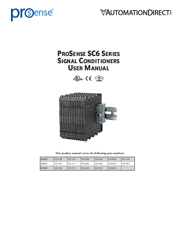
ProSense SC6 Series Signal Conditioners
User Manual

0068060 0068061 0068062

This product manual covers the following part numbers:

SC6-1100 SC6-1101 SC6-1102

SC6-1110 SC6-1111 SC6-1112

SC6-2200 SC6-2220 SC6-3200

SC6-3220 SC6-4102 SC6-4112

SC6-5200 SC6-6102 SC6-6200

SC6-7102 SC6-PCU1

User Manual - ProSense SC6 Series Signal Conditioners

ProSense SC6 Series Signal Conditioners User Manual

Please include the Manual Number and the Manual Issue, both shown below, when communicating with Technical Support regarding this publication.

Manual Number: Issue: Issue Date:

ProSense SC6 Series Signal Conditioners Manual 1st Edition 06/18

Issue 1st Edition

Publication History

Date

Description of Changes

06/18

Original

2

www.AutomationDirect.com

SC6 Series 1st Ed.

User Manual - ProSense SC6 Series Signal Conditioners
Table of Contents

Contents
1 - Warnings.............................................................................................. 4
2 - Symbol Identification........................................................................... 4
3 - Safety Instructions................................................................................ 4
3.1 - Receipt and unpacking.........................................................................................4 3.2 - Environment.........................................................................................................4 3.3 - Installing...............................................................................................................4 3.4 - Cleaning...............................................................................................................5
4 - Supply Voltage Options....................................................................... 5
5 - Installing and Uninstalling the SC6 Series.......................................... 6
6 - Installation on DIN rail / power rail.................................................... 6
6.1 - In-Rail-Bus-Set Installation.....................................................................................7
7 - Side Label............................................................................................. 8
8 - Common Technical Specifications....................................................... 8
9 - 4 -Wire, External Powered Analog Signal Input Modules Technical Specifications ...................................................................... 9
10 - 2 -Wire, Loop Powered Analog Signal Input Modules Technical Specifications................................................................... 10
11 - Temperature Input Modules - Technical Specifications.................. 11
12 - Power Connector Module - Technical Specifications...................... 12
13 - Output Load Deratings.................................................................... 12
14 - Wiring Diagrams.............................................................................. 13
15 - DIP Switch Settings.......................................................................... 17
16 - L ED Indication for Analog Input Modules (SC6-1100, -1110, -2200, -2220, -3200, -3220)................................ 18
17 - L ED Indication for Temperature Input Modules (SC6-5200, -6200)............................................................................. 19

3

www.AutomationDirect.com

SC6 Series 1st Ed.

User Manual - ProSense SC6 Series Signal Conditioners

1 - Warnings

General

To avoid the risk of electric shock and fire, the safety instructions of this guide must be observed and the guidelines followed. The specifications must not be exceeded, and the device must only be applied as described in the following. Prior to the commissioning of the device, this installation guide must be examined carefully. Only qualified personnel (technicians) should install this device. If the equipment is used in a manner not specified by the manufacturer, the protection provided by the equipment may be impaired. Until the device is installed, do not connect hazardous voltages to the device.

To avoid explosion and serious injury, modules having mechanical failures must not be used.

Caution

Modules are not repairable.
In applications where hazardous voltage is connected to in-/outputs of the device, sufficient spacing or isolation from wires, terminals and enclosure - to surroundings (incl. neighboring devices), must be ensured to maintain protection against electric shock.

Potential electrostatic charging hazard. To avoid the risk of explosion due to electrostatic charging of the enclosure, do not handle the units unless the area is known to be safe, or appropriate safety measures are taken to avoid electrostatic discharge.

2 - Symbol Identification
Triangle with an exclamation mark: Read the manual before installation and commissioning of the device in order to avoid incidents that could lead to personal injury or mechanical damage.
The CE mark indicates device is in compliance with the essential requirements of the directives.

3 - Safety Instructions

3.1 - Receipt and unpacking
Unpack the device without damaging it and check whether the device type corresponds to the one ordered. The packing should always follow the device until the unit has been permanently installed.
3.2 - Environment
Avoid direct sun light, dust, high temperatures, mechanical vibrations and shock, as well as heavy moisture and rain. If necessary, heating in excess of the stated limits for ambient temperatures should be avoided by way of ventilation. The device can be used for Measurement Category II and Pollution Degree 2. The modules are designed to operate safely at an altitude of 2000m or less.

3.3 - Installing
Only technicians who are familiar with the technical terms, warnings, and instructions in the manual and who are able to follow these should connect the device.
Should there be any doubt as to the correct handling of the device, please contact AutomationDirect.com.
Installation and connection of the device should comply with national legislation for installing of electric materials, e.g. wire cross section, protective fuse, and location.
Descriptions of input / output and supply connections are shown in this installation guide and on the side label.
The device is provided with field wiring terminals and shall be supplied from a Power Supply having double or reinforced insulation. A power switch should be readily accessible and close to the device. The power switch shall be marked as the disconnecting unit for the device.
The SC6 Series must be installed on a DIN rail that complies with EN 60715. Note: No mounting orientation restrictions.
UL installation
Use 60�C/75�C copper conducters only. Wire size . . . . . . . . . . . . . . . . . . . . . . . . . . . . . . . . . . . . . . . . .AWG 26-12
UL file number . . . . . . . . . . . . . . . . . . . . . . . . . . . . . . . . . . . .E498965
The device is an Open Type Listed Process Control Equipment. To prevent injury resulting from accessability to live parts the equipment must be installed in an enclosure.
The power supply unit must comply with NEC Class 2, as described by the National Electrical Code� (ANSI / NFPA 70).

4

www.AutomationDirect.com

SC6 Series 1st Ed.

User Manual - ProSense SC6 Series Signal Conditioners
cFMus installation in Division 2 or Zone 2 FM18US0045X . . . . . . . . . . . . . . . . . . . . . . . . . . Cl I, Div. 2, Group A, B, C, D T4
or Cl I, Zone 2, AEx nA IIC T4 FM18CA0023X . . . . . . . . . . . . . . . . . . . . . . . . . . Cl I, Div. 2, Group A, B, C, D T4
or Cl I, Zone 2, Ex nA IIC T4
In Class I, Division 2 or Zone 2 installations, the subject equipment shall be installed within a tool-secured enclosure which is capable of accepting one or more of Class I, Division 2 wiring methods specified in the National Electrical Code (ANSI/NFPA 70) or in Canada in the Canadian Electrical Code (C22.1). The SC6 Series Isolators and Converters must be connected to limited output NEC Class 2 circuits, as outlined in the National Electrical Code� (ANSI / NFPA 70), only. If the devices are connected to a redundant power supply (two separate power supplies), both must meet this requirement. When installed in outdoor or potentially wet locations the enclosure shall at a minimum meet the requirements of IP54. Warning: Substitution of components may impair suitability for Zone 2 / Division 2. Warning: To prevent ignition potential in an explosive atmosphere, disconnect power before servicing. Do not separate connectors
while circuit is energized in a potentially explosive atmosphere. Warning: Do not install or remove devices from a live power rail when an explosive gas mixture is present.
3.4 - Cleaning
When disconnected, the device may be cleaned with a cloth moistened with distilled water.

4 - Supply Voltage Options
The technical specifications specify the maximum required power at nominal operating values, e.g. 24V supply voltage, 60�C ambient temperature, 600  load, and 20mA output current.

DIN rail solution - device daisy chain: The units can be supplied with 24VDC �30% via direct wiring and a loop between the devices.
Protective fuse: 2.5 A.

Power rail solution #2: The SC6-PCU1 power connector unit allows easy connection of a 24 VDC / 2.5 A source to the power rail.
Protective fuse: 2.5 A.

SC6-PCU1

Protective fuse: 0.4 A.
Power rail solution #1: Alternately, you can connect 24VDC to any one SC6 Series device with power rail connector which will then energize other units on the rail. The terminals can pass a current of 400mA maximum.
Note: SC6-1101, -1102, -1111, -1112, -4102, -4112, -6102, -7102 are not supplied via the DIN rail solution. Direct terminal wiring to each device is required for these models.
External fuse characteristics: The 2.5 A fuse must break after not more than 120 seconds at 6.4 A.

5

www.AutomationDirect.com

SC6 Series 1st Ed.

User Manual - ProSense SC6 Series Signal Conditioners
5 - Installing and Uninstalling the SC6 Series
Picture 1: Installing on DIN rail / power rail. Click the device onto the rail.

Picture 2: Uninstalling from DIN rail / power rail. First, remember to uninstall the connectors with hazardous voltages. Detach the device from the DIN rail by lifting the bottom lock.
Note: Always use a screwdriver to uninstall units and avoid excessive force to prevent damaging the unit.
Picture 3: Wire size AWG 26-12 / 0.13 - 2.5 mm2 stranded wire. Screw terminal torque 0.5 N�m.

6 - Installation on DIN rail / power rail

End Bracket (part number KN-EB7-10)

The devices in the SC6 Series can be installed on a DIN rail or on a power rail (only SC6-1100, -1110, -2200, -2220, -3200, -3220, -5200 and -6200). It is recommended that the modules be supported by end brackets (part number KN-EB7-10). Power supply units can be installed on the power rail according to customer requirements. If you want to install a SC6 Series device with power rail connectors on a standard DIN rail, the head of the screws holding the 7.5 mm DIN rail shall be no more than 3.5 mm high in order to avoid short circuit between the power rail connectors on the SC6 Series device and the screws.
35 mm > 24 mm
< 3.5 mm

6

www.AutomationDirect.com

SC6 Series 1st Ed.

User Manual - ProSense SC6 Series Signal Conditioners

6.1 - In-Rail-Bus-Set Installation
Step 1 Put the BUS PCB into the carrier profile and then put the carrier profile into the DIN rail
Carrier profile with installed BUS PCB

Step 2
Put on the right and left safety cap

7.5 1

35

Pay attention to the sequence: a) put the cap in from above laid on the carrier profile b) snap the cap on below
Dismantling in reversed sequence

Safety cap left Carrier rail cover

Step 3
Snap the devices on the In-Rail-Bus

Safety cap right BUS PCB Carrier profile

DIN rail (Purchased separately)

Safety cap on both sides tight to the carrier profile The safety cap fixes the carrier profile in the DIN rail and protects the ends of the BUS

Part No. Each Set Includes

In-Rail-Bus-Set / 250mm 0068060
BUS-PCB 250mm Carrier profile 250mm Carrier rail cover 250mm
Safety cap right Safety cap left

In-Rail-Bus-Set / 500mm 0068061
BUS-PCB 500mm Carrier profile 500mm Carrier rail cover 500mm
Safety cap right Safety cap left

In-Rail-Bus-Set / 750mm 0068062
BUS-PCB 750mm Carrier profile 750mm Carrier rail cover 750mm
Safety cap right Safety cap left

Use carrier rail cover provided to protect exposed sections of the BUS PCB

Safety end cap

Carrier rail cover

Bus PCB mounted in carrier profile
DIN rail (order separately)

Safety end cap

SC6 signal conditioners

KN-EB7-10 end bracket (order separately)

SC6-PCU1 power connection unit

7

www.AutomationDirect.com

SC6 Series 1st Ed.

User Manual - ProSense SC6 Series Signal Conditioners

7 - Side Label

Terminal numbers

AutomationDirect 3505 Hutchinson Road Cumming, GA 30040 800-633-0405 www.automationdirect.com
Part number
DIP-switch settings

}

} Pin connections
} Approvals

}

8 - Common Technical Specifications

SC6 Series Common Technical Specifications

Environmental Conditions

Operating Temperature

-25�C to +70�C (-13�F to +158�F)

Storage Temperature

-40�C to +85�C (-40�F to +185�F)

Calibration Temperature

+20�C to +28�C (+68 to +82.4�F)

Relative Humidity

< 95% RH (non-cond.)

Protection Degree

IP20*

Mechanical Specifications

Dimensions (HxWxD)

113 x 6.1 x 115 mm

Weight Approx.

70g

DIN Rail Type

DIN EN 60715 - 35mm

Wire Size

0.13...2.5 mm2 / AWG 26...12 stranded wire

Screw Terminal Torque

0.5 N�m

Vibration

2 to 25 Hz 25 to 100 Hz

� 1.6 mm � 4g

Observed Authority Requirements

EMC LVD RoHS 2

2014/30/EU 2014/35/EU 2011/65/EU

cULus, Standard for Safety

UL 61010-1, File E498965

Approvals

cFMus

FM18US0045X, FM18CA0023X

Safe Isolation

EN 61140

* Installation in pollution degree 2 & overvoltage category II, No corrosive gases

8

www.AutomationDirect.com

SC6 Series 1st Ed.

User Manual - ProSense SC6 Series Signal Conditioners
9 - 4-Wire, External Powered Analog Signal Input Modules - Technical Specifications

4- Wire, External Powered Analog Signal Input Modules - Technical Specifications

Part No.

SC6-1100 SC6-2200

SC6-1110

SC6-2220

SC6-3200

SC6-3220

Application

One channel

One channel

Signal splitter

Signal splitter

One channel

Signal splitter

DIP switch configurable

No

Yes

No

Yes

Yes

Yes

Supply voltage

16.8 - 31.2 VDC (terminals or bus rail)

Max. required power*

0.80 W

1.20 W

0.80 W

1.20 W

0.80 W

1.20 W

Max. power dissipation**

0.60 W

0.55 W

0.48 W

0.60 W

0.43 W

0.43 W

Isolation voltage, test

2.5 kVAC

Isolation voltage, working

300VAC (reinforced) / 250VAC (Zone 2, Div. 2)

Double isolation

Input / Output 1 / Output 2 / Supply

Signal dynamics, input / output

Analog signal chain

Signal / noise ratio

> 60dB

Cut-off frequency (3 dB)

> 100Hz

>100Hz or 10Hz (DIP switch selectable)

Response time filter (0-90%, 100-10%)

< 7ms

< 7ms or < 44ms (DIP switch selectable)

Accuracy

< +/-0.05% of span

Temperature coefficient

< +/-0.01% of span / �C

EMC immunity influence

< +/-0.5% of span

Extended EMC immunity:

NAMUR NE 21, A criterion, burst

< +/-1% of span

Current input

Overall measurement range

0-23 mA

- 23mA to + 23mA

Selectable measurement ranges

0-20 mA, 4-20 mA

+/- 10mA, +/- 20mA

Input voltage drop Input resistance Transmitter (Tx) auxiliary supply

< 1.5 VDC

190 nominal @ 4mA 70 nominal @ 20mA

None

> 17VDC / 20mA

None

> 17VDC / 20mA

< 1VDC 40 nominal
None

Voltage input

Overall measurement range

0-10.25 VDC

- 11.5 VDC to + 11.5 VDC

Selectable measurement range

0-10 VDC, 2-10 VDC, 0-5 VDC, 1-5 VDC

+/-5 VDC, +/- 10 VDC

Input resistance

 500 kohms

 1 Mohms

Current output

Overall signal range (span)

0-23 mA

Selectable signal ranges

0-20 mA, 4-20 mA

0-20 mA, 4-20 mA or +/-10 mA, +/-20 mA

Load

 600 ohms

 300 ohms / channel

 600 ohms

 300 ohms / channel

Load stability

< 0.002% of span / 100 ohms

< 0.02% of span / 100 ohms

Current limit

 28mA

Voltage output

Overall signal range (span) Selectable signal ranges Load (minimum)

None

0-10 VDC

None

None

0-10 VDC, 2-10 VDC, 0-5 VDC, 1-5 VDC

None

None

> 10 kohms

None

*Max. required power is the maximum power needed at power supply terminals or rail connector. **Max. power dissipation is the maximum power dissipated at nominal operating values. "of span" = of the seleted range

0-10 VDC 0-10 VDC, 2-10 VDC, 0-5 VDC, 1-5 VDC
> 10 kohms

9

www.AutomationDirect.com

SC6 Series 1st Ed.

User Manual - ProSense SC6 Series Signal Conditioners
10 - 2-Wire, Loop Powered Analog Signal Input Modules - Technical Specifications

2-Wire, Loop Powered Analog Signal Input Modules - Technical Specifications

Part No.

SC6-1101

SC6-1111

SC6-4102

SC6-4112

SC6-1102

SC6-1112

Application

One channel

Two channel

One channel

Two channel

One channel

Two channel

DIP switch configurable

No

No

No

No

No

No

Loop supply voltage

None (powered by input signal)

6-35 VDC

Power dissipation

30mW / channel

50mW / channel

V terminal x I / channel

Isolation voltage, test

2.5 kVAC

Isolation voltage, working

300 VAC (reinforced) / 250 VAC (Zone 2, Div. 2)

Double isolation

Input 1 / Input 2 / Output 1 / Output 2

Signal dynamics, input / output

Analog signal chain

Signal / noise ratio

> 60dB

Cut-off frequency (3 dB)

100Hz

Response time (0-90%, 100-10%)

< 5ms

Accuracy Temperature coefficient EMC immunity influence

 +/-10uA + 0.05% of max. value of span  � 2uA / �C

 � 8uA

Vloop supply  24V: � 0.48 uA/�C (>25�C); � 1.68 uA/�C (< 25�C)
Vloop supply > 24V: � 0.02 uA/�C x Vloop supply (> 25�C); +/-0.047 uA/degC x Vloop supply (<25�C)

Vloop supply  24V: � 0.48 uA/�C (> 25�C); � 1.12 uA/�C (< 25�C)
Vloop supply >24V: � 0.02 uA/�C x Vloop supply (> 25�C); � 0.047 uA/�C x Vloop supply (< 25�C)

< � 0.5% of span

Extended EMC immunity:

NAMUR NE 21, A criterion, burst

< � 1% of span

Current input

Overall measurement range Nominal measurement range Signal conversion Input voltage drop Input resistance Transmitter (Tx) auxiliary supply Current output

0-23 mA
0-20.5 mA 10uA start up current, typical
1.35 + (0.02335*Rout load) @ 23mA max. Rout load 600: 15.36 V Rout load 250: 7.19 V Rout load @ 600: 668* Rout load @250: 313*
None

3.5-23 mA 3.8-20.5 mA 1:1 2.5 VDC input to output Not applicable 3.5-32.5 VDC (Loop supply voltage - Input voltage drop)

 3VDC 130 nominal
None

Overall signal range (span)

0-23 mA

3.5-23 mA

Nominal signal range

0-20.5 mA

3.8-20.5 mA

Load

 600 ohms

900 ohms max at 24 Vloop supply 1450 ohms max at 35 Vloop supply See derating chart above 60�C ambient

900 ohms max at 24 Vloop supply 1450 ohms max at 35 Vloop supply See derating charts above 50�C ambient

Load stability

<0.01% of span / 100 ohms

N/A

"of span" = 0-20 mA
* Because the input signal drives both the SC6 unit and the output signal loop, the input resistance changes with the output load. Calculate the input voltage drop using the formula shown and divide by the maximum current signal of 23mA to determine the Input resistance.

10

www.AutomationDirect.com

SC6 Series 1st Ed.

User Manual - ProSense SC6 Series Signal Conditioners

11 - Temperature Input Modules - Technical Specifications

Temperature Input Modules - Technical Specifications

Part No.

SC6-5200

SC6-6200

SC6-7102

SC6-6102

Application

One channel

One channel

One channel

One channel

DIP switch configurable

Yes

Yes

Yes

Yes

Supply voltage

16.8 - 31.2 VDC (terminals or bus rail)

5.5 - 35 VDC

3.3 - 35 VDC

Max. power dissipation

0.7 W

0.7 W

0.8 W

0.8 W

Isolation voltage, test

2.5 kVAC

None

Isolation voltage, working

300VAC (reinforced) / 250VAC (Zone 2, Div. 2)

None

Double isolation

Input / Output 1 / Supply

None

Signal dynamics, input / output

23bit / 18bit

Signal / noise ratio

> 60dB

Response time (0-90%, 100-10%) Accuracy

Basic:  0.5�C; General:  �0.05% of span

< 30ms or < 300ms, DIP switch selectable

Basic:  0.1�C; General:  �0.05% of span

Basic:  0.1�C (Pt100),  0.5�C (TC);
General:  �0.05% of span

Basic:  0.2�C; General:  �0.1% of span

Temperature coefficient

0.1�C/�C (basic) or  �0.01% of span/�C

0.02�C/�C (basic) or  �0.01% of span/�C

0.1�C/�C (basic) or  �0.01% of span/�C

0.02�C/�C (basic) or  �0.01% of span/�C

EMC immunity influence

< �0.5% of span

Extended EMC immunity:

NAMUR NE 21, A criterion, burst

< �1% of span

RTD (Pt100) input

Overall measurement range

N/A

-200 to 850�C (IEC 60751)

Min. measurement span

N/A

10�C

Sensor current

N/A

< 150uA

Sensor cable resistance

N/A

< 50 ohms per wire

Effect of sensor cable resistance 3/4-wire

N/A

< 0.002 ohm/ohm

Sensor error detection

N/A

Yes, DIP switch selectable

Broken sensor

N/A

> 800 ohms

Shorted sensor

N/A

< 18 ohms

Thermocouple (TC) input

Overall mesasurement range, Type J

-100 to 1200�C (IEC60584-1)

N/A

-100 to 1200�C (IEC60584-1)

N/A

Overall mesasurement range, Type K

-180 to 1372�C (IEC60584-1)

N/A

-180 to 1372�C (IEC60584-1)

N/A

Selectable measurement range

See temperature range programming table

Min. measurement span

50�C

N/A

50�C

N/A

Sensor cable resistance

< 5 kohm per wire

N/A

< 5 kohm per wire

N/A

External Pt100 CJC sensor accuracy

< �0.15�C

N/A

< �0.15�C

N/A

Internal CJC sensor accuracy

< �2.5�C

N/A

<+/-2.5�C

N/A

Open thermocouple detection

Yes, DIP switch selectable

N/A

Yes, DIP switch selectable

N/A

External CJC error detection

Yes, DIP switch selectable

N/A

Yes, DIP switch selectable

N/A

Internal CJC error detection

Yes

N/A

Yes

N/A

Current output

Overall signal range (span)

0 / 3.8-20.5 mA

3.8-20.5 mA

Nominal signal range

0 / 4-20 mA DIP switch selectable

4-20 mA or 20-4 mA, DIP switch selectable

Load

 600 ohms

Rload=(Vsupply-5.5) / 0.023 ohms Rload=(Vsupply-3.3) / 0.023 ohms

Sensor error output

Downscale: 0 / 3.5 mA, Upscale: 23mA DIP switch selectable

Downscale: 3.5 mA, Upscale: 23mA DIP switch selectable

Voltage output

Overall signal range (span)

0 / 0.875-5.125 V, 0 / 1.75-10.25 V

N/A

Nominal signal range

0 / 1-5 V, 0 / 2-10 V DIP switch selectable

N/A

Load

 10 kohms

N/A

Sensor error output

Downscale: 0V, Upscale: 5.5 / 11V DIP switch selectable

N/A

Load stability

 0.01% of span / 100 ohms

Updating time

10ms

11

www.AutomationDirect.com

SC6 Series 1st Ed.

User Manual - ProSense SC6 Series Signal Conditioners
12 - Power Connector Module - Technical Specifications

Power Connection Module - Technical Specifications

Part No.

SC6-PCU1

Supply voltage

16.8-31.2 VDC

Internal power dissipation

0.25 W max.

Required external fuse

2.5 A

13 - Output Load Deratings
SC6-4102, -4112 Output Load Derating @ Tamb. = 70�C:

Load RA in

1450
1000 900
500 275
0 0

Undervoltage condition
Correct operating
range

6 12 18 24 Voltage Vsupply in V*

Temperature limitation @ Tamb. = 70�C Do not operate in this area.
30 35

SC6-4102, -4112 Output Load Derating @ Tamb. = 60�C . . . No limiting issues within operating range

SC6-1102, -1112 Output Load Derating @ Tamb. = 70�C:

Load RA in

1450 1062 1000
900 512

Undervoltage condition

Correct operating range

Temperature limitation @ Tamb. = 70�C
Do not operate in this area.

0 14
0 6 12 18 24 30 35 Voltage Vsupply in V*
SC6-1102, -1112 Output Load Derating @ Tamb. = 60�C:

1450 1000
900

Undervoltage condition

Load RA in

500
0 0

Correct operating range

Temperature limitation

@ Tamb. = 60�C

25 6 12 18 24 30 35

Do not operate in this area.

Voltage Vsupply in V*

SC6-1102, -1112 Output Load Derating @ Tamb. = 50�C . . . No limiting issues within operating range
* Vsupply: The supply voltage for the loop covering both the SC6 output terminal voltage and the voltage across the load resistor RA .
RA = The input impedance in the PLC + the load in the loop (incl. the cable resistance).

12

www.AutomationDirect.com

SC6 Series 1st Ed.

User Manual - ProSense SC6 Series Signal Conditioners

14 - Wiring Diagrams

Note: The SC6 2-wire Transmitter Input is a current input which provides an excitation voltage to the input device, otherwise known as an active or sourcing input, while the SC6 Current Input requires the input device be provided with an external excitation voltage, otherwise known as a passive or sinking input.

SC6-PCU1

SC6-1100

4

5

3

6

2

7

Supply +

1

Supply
8

Supply -

Current input

+

4

-

3

Input

2

1

5 Output 1
6
7 Supply
8

Current output
+ mA -
Supply +
Supply -

No connection Rail, + Rail, -
No connection No connection

No connection Rail, +24 VDC Rail, -24 VDC
No connection No connection

SC6-1110

Current input

+

4

-

3

Input

5 Output 1
6

+
mA
-
Current output

2 Output 2
1

7 Supply
8

Current output
+ mA -
Supply +
Supply -

No connection Rail, +24 VDC Rail, -24 VDC
No connection No connection

SC6-2200

Current input
+
-

Voltage input
-
+

2-wire Transmitter
input
4 Loop -
Tx
3 Loop+

Input

2

1

5 Output
6

Voltage output
+ V
-

Current output
+ mA -

7 Supply
8

Supply + Supply -

No connection Rail, +24 VDC Rail, -24 VDC
No connection No connection

13

www.AutomationDirect.com

SC6 Series 1st Ed.

User Manual - ProSense SC6 Series Signal Conditioners

SC6-2220

Current input
+
-

Voltage input
-
+

2-wire Transmitter
input
4 Loop -
Tx
3 Loop+

Input

5 Output 1
6

Voltage Output
+ V
-

Current Output
+ mA -

+ mA
-
Current output

+

2

V

-
Voltage

1

Output 2

output

7 Supply
8

Supply + Supply -

SC6-3200

Current input
+ (�)
-

Voltage input

-

4

(�)

+

3 Input

2

1

5 Output
6

Voltage output
+ V
-

Current output
+ mA -

7 Supply
8

Supply + Supply -

No connection Rail, +24 VDC Rail, -24 VDC
No connection No connection

No connection Rail, +24 VDC Rail, -24 VDC
No connection No connection

SC6-3220

Current input
+ (�)
-

Voltage input

-

4

(�)

+

3

Input

5 Output 1
6

Voltage Output
+ V
-

Current Output
+ mA -

+ mA
-
Current output

+

2

V

-
Voltage

1

Output 2

output

7 Supply
8

Supply + Supply -

SC6-1101

Current input

+

4

-

3

Input

2

1

5 Output
6

Current output
+
0...20 mA
-

7

8

No connection Rail, +24 VDC Rail, Gnd

No connection

No connection

Bipolar Input to bipolar output wiring set-up:

Current input
+ (�)
-

Voltage input

-

4

(�)

+

3

Input

5 Output 1
6

2 1 Output 2

7 Supply
8

Current Output
+ (�) mA
-

14

www.AutomationDirect.com

SC6 Series 1st Ed.

User Manual - ProSense SC6 Series Signal Conditioners

SC6-1111

Current input

+

4

Input

-

3 ch. 1

+

2

Input

-

1 ch. 2

5 Output ch. 1 6
7 Output ch. 2 8

Current output
+
0...20 mA
-
+
0...20 mA
-

SC6-4112

2-wire transmitter input

Loop + Tx
Loop -

4 Input
3 ch. 1

Loop + Tx
Loop -

2 Input
1 ch. 2

Current output

5 Output ch. 1 6

+ 4...20 mA
-

+

7 4...20 mA

Output

-

ch. 2 8

+V supply +V supply

SC6-4102

2-wire transmitter input

Loop +

4

Tx

Loop -

3

Input

Current output

+

5 4...20 mA

Output

-

6

+V supply

2

7

1

8

SC6-1112

Current input

-

4

+

Input 3 ch. 1

-

2

+

Input 1 ch. 2

Current output

+
5 4...20 mA

Output

-

ch. 1 6

+

7 4...20 mA

Output

-

ch. 2 8

+V supply +V supply

SC6-1102

Current input

-

4

+

3

Input

Current output

Output

+
5 4...20 mA
-
6

+V supply

2

7

1

8

15

www.AutomationDirect.com

SC6 Series 1st Ed.

User Manual - ProSense SC6 Series Signal Conditioners

SC6-5200

TC J & K 4

Current output

+

5

mA

Voltage output
+ V

+

3

6

-

-

-

2 CJC

7

Supply +

1 Optional External CJC (2- or 3-wire Pt100)

8

Supply -

No connection Rail, +24 VDC Rail, -24 VDC
No connection No connection

RTD Input
4 3 2 1

SC6-6200

Current output
+ 5
mA

6

-

Voltage output
+
V
-

7

Supply +

8

Supply -

No connection Rail, +24 VDC Rail, -24 VDC
No connection No connection

RTD Input

SC6-7102

TC K & J input 4

+

3

-

2 CJC

1

Optional External CJC (2- or 3-wire
Pt100)

Current output

5

+

+V supply

4...20 mA / 20-4 mA

6-

7

8

RTD Input
4 3 2 1

SC6-6102

Current output

+

+V supply

5 4...20 mA / 20-4 mA

-

6

7

8

(non-isolated)

16

www.AutomationDirect.com

SC6 Series 1st Ed.

User Manual - ProSense SC6 Series Signal Conditioners
15 - DIP Switch Settings
The part numbers listed below are configured with DIP switches which are located on the side of the module and can be adjusted with a small screw driver or other implement.

SC6-2200

1 2 3 4 5 6 7 8 9 10 DIP Switch


0...20mA 4...20mA


0...10V


2...10V 0...5V


1...5V


0...20mA Loop 4...20mA Loop

In

Out

 = ON

SC6-2220

1 2 3 4 5 6 7 8 9 10 DIP Switch

0...20mA


 4...20mA


0...10V

      2...10V       0...5V

         1...5V


0...20mA Loop 4...20mA Loop

In

Out1 Out2  = ON

SC6-3200

1 2 3 4 5 6 7 8 9 10 DIP Switch

On

0...20mA

Off


4...20mA

Filter


0...10V


2...10V 0...5V


1...5V


-20...+20mA -10...+10mA

-10...+10V


-5...+5V

In Out

 = ON

SC6-3220

1 2 3 4 5 6 7 8 9 10 DIP Switch

On  Off

0...20mA


 4...20mA

Filter


0...10V

    2...10V     0...5V

      1...5V


 -20...+20mA

       -10...+10mA

-10...+10V


-5...+5V

In Out 1 Out 2  = ON

SC6-5200

Sensor S1 1 2 3

TC J (Int. CJC)


TC K(Int. CJC)

TC J(Ext. CJC)

TC K(Ext. CJC)

Output S1 4 5 6

0...20 mA 4...20 mA 0...10 V 2...10 V 0...5 V 1...5 V


 = ON

Sensor Error Detection S1 7

None

Enable


Output Error Level Downscale Upscale

S1 8

Noise Supp.S1 9 Resp.T. S1 10

50 Hz

< 30 ms

60 Hz

 300 ms

SC6-6102

Sensor S1 1 2 3

Pt100, 2w

Pt100, 3w


Pt100, 4w

Output S1 4 5 6 4...20 mA  20...4 mA
 = ON

Sensor Error Detection S1 7

None

Enable


Output Error Level Downscale Upscale

S1 8

Noise Supp.S1 9 Resp.T. S1 10

50 Hz

< 30 ms

60 Hz

 300 ms

SC6-6200

Sensor S1 1 2 3

Pt100, 2w

Pt100, 3w


Pt100, 4w

Output S1 4 5 6

0...20 mA 4...20 mA 0...10 V 2...10 V 0...5 V 1...5 V


 = ON

Sensor Error Detection S1 7

None

Enable


Output Error Level Downscale Upscale

S1 8

Noise Supp.S1 9 Resp.T. S1 10

50 Hz

< 30 ms

60 Hz

 300 ms

SC6-7102

Sensor S1 1 2 3

Pt100, 2w

Pt100, 3w


Pt100, 4w

TC J (Int. CJC)


TC K(Int. CJC)

TC J(Ext. CJC)

TC K(Ext. CJC)

Output S1 4 5 6 4...20 mA  20...4 mA
 = ON

Sensor Error Detection S1 7

None

Enable


Output Error Level Downscale Upscale

S1 8

Noise Supp.S1 9 Resp.T. S1 10

50 Hz

< 30 ms

60 Hz

 300 ms

17

www.AutomationDirect.com

SC6 Series 1st Ed.

User Manual - ProSense SC6 Series Signal Conditioners

SC6-5200, SC6-6200, SC6-6102, SC6-7102 Models:

Start Temp. 1 2 3 4

-200�C (-328�F)

-180�C (-292�F)

�

-150�C (-238�F)

�

-100�C (-148�F)

��

-50�C (-58�F)

�

-25�C (-13�F)

��

-10�C (14�F)

��

-5�C (23�F)

���

0�C (32�F) �

5�C (41�F) �

�

10�C (50�F) �

�

20�C (68�F) �

��

25�C (77�F) � �

50�C (122�F) � �

�

100�C (212�F) � � �

200�C (392�F) � � � �

Sens.Type Pt100 TC J TC K

Temp. Range -200�C (-328�F) to
850�C (1562�F) -100�C (-148�F) to 1200�C (2192�F) -180�C (-292�F) to 1372�C (2502�F)

Temperature Range Programming

DIP S2 � = ON Temperature Range �C (�F)

End Temp. 5 6 7 8 9 10

End Temp. 5 6 7 8 9 10

0�C (32�F)

105�C (221�F) � � �

5�C (41�F)

� 110�C (230�F) � � �

10�C (50�F)

�

115�C (239�F) � � � �

15�C (59�F)

� � 120�C (248�F) � �

20�C (68�F)

�

125�C (257�F) � �

�

25�C (77�F)

� � 130�C (266�F) � � �

30�C (86�F)

��

135�C (275�F) � � � �

35�C (95�F)

� � � 140�C (284�F) � � �

40�C (104�F)

�

145�C (293�F) � � � �

45�C (113�F)

�

� 150�C (302�F) � � � �

50�C (122�F)

��

160�C (320�F) � � � � �

55�C (131�F)

� � � 170�C (338�F) �

60�C (140�F)

��

180�C (356�F) �

�

65�C (149�F)

� � � 190�C (374�F) �

�

70�C (158�F)

���

200�C (392�F) �

��

75�C (167�F)

� � � � 225�C (437�F) �

�

80�C (176�F)

�

250�C (482�F) �

��

85�C (185�F)

�

� 275�C (527�F) �

��

90�C (194�F)

�

�

300�C (572�F) �

���

95�C (203�F)

�

� � 325�C (617�F) � �

100�C (212�F)

��

350�C (662�F) � �

�

Note: �F values are calculated equivalents for �C values

End Temp. 5 6 7 8 9 10

375�C (707�F) � � �

400�C (752�F) � � � �

450�C (842�F) � � �

500�C (932�F) � � � �

550�C (1022�F) � � � �

600�C (1112�F) � � � � �

650�C (1202�F) � �

700�C (1292�F) � �

�

750�C (1382�F) � �

�

800�C (1472�F) � �

��

850�C (1562�F) � � �

900�C (1652�F) � � � �

950�C (1742�F) � � � �

1000�C (1832�F) � � � � �

1050�C (1922�F) � � �

1100�C (2012�F) � � �

�

1150�C (2102�F) � � � �

1200�C (2192�F) � � � � �

1250�C (2282�F) � � � �

1300�C (2372�F) � � � � �

1350�C (2462�F) � � � � � 1372�C (2502�F) � � � � � �

16 - LED Indication for Analog Input Modules (SC6-1100, -1110, -2200, -2220, -3200, -3220)

LED Indication
The device is equipped with a green power LED in the front to indicate the operation status, see the table below:

Condition
No supply / device error
Power-up or restart
Device OK
Incorrect DIP-switch setting Restarting due to:
Supply error/hardware. RAM or program flow error

LED Indication for Analog Input Modules

LED

Output and Loop Supply

Action Required

OFF
1 Flash (0.5 s OFF + 0.5 s ON)
Flashing 13Hz (15ms ON) Flashing 1Hz (15ms ON)

De-energized De-energized
Energized De-energized

Connect supply / replace device -
Correct setting and re-power
device

Flashing 1Hz (0.5 s ON)

De-energized

Adjust supply / replace device

18

www.AutomationDirect.com

SC6 Series 1st Ed.

User Manual - ProSense SC6 Series Signal Conditioners
17 - LED Indication for Temperature Input Modules (SC6-5200, -6200)

LED Indication
The device is equipped with a green power LED in the front to indicate the operation status, see the table below:

Condition

LED Indication for Temperature Input Modules

LED

Output and Loop Supply Action Required

No supply / device error Power-up or restart Device OK
Incorrect DIP-switch setting

OFF
1 Flash (0.5 s OFF + 0.5 s ON)
Flashing 13Hz (15ms ON) Flashing 1Hz (500ms ON)

De-energized De-energized
Energized De-energized

Connect supply / replace device -
Correct setting and re-power
device

Sensor error indication

Flashing 1Hz (15ms ON)

Up- or Downscale

Check sensor

19

www.AutomationDirect.com

SC6 Series 1st Ed.