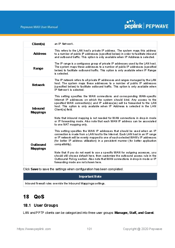
Home
›
peplink
›
peplink Pepwave Max BR1 Mini LTE Home Business and Outdoor Activities 4G LTE Router User Manual

peplink Pepwave Max BR1 Mini LTE Home Business and Outdoor Activities 4G LTE Router User Manual
File info: application/pdf · 90 pages · 5.53MB
Pepwave MAX User Manual 8.0.1 (BR1 Mini, cert)
User Manual-2
PISMO LABS TECHNOLOGY LIMITED P1930LITER6 PEPWAVE / peplink Wireless Product U8G-P1930LITER6 U8GP1930LITER6 p1930liter6
download (pdf)
P1930LITER6 Pepwave / Peplink Wireless Product by PISMO LABS
Extracted Text
Client(s)

an IP Network.

Address

This refers to the LAN hosts private IP address. The system maps this address to a number of public IP addresses (specified below) in order to facilitate inbound and outbound traffic. This option is only available when IP Address is selected.

Range

The IP range is a contiguous group of private IP addresses used by the LAN host.
The system maps these addresses to a number of public IP addresses (specified
below) to facilitate outbound traffic. This option is only available when IP Range is selected.

Network

The IP network refers to all private IP addresses and ranges managed by the LAN host. The system maps these addresses to a number of public IP addresses (specified below) to facilitate outbound traffic. This option is only available when IP Network is selected.

Inbound Mappings

This setting specifies the WAN connections and corresponding WAN-specific Internet IP addresses on which the system should bind. Any access to the specified WAN connection(s) and IP address(es) will be forwarded to the LAN host. This option is only available when IP Address is selected in the LAN Client(s) field.
Note that inbound mapping is not needed for WAN connections in drop-in mode or IP forwarding mode. Also note that each WAN IP address can be associated to one NAT mapping only.

Outbound Mappings

This setting specifies the WAN IP addresses that should be used when an IP connection is made from a LAN host to the Internet. Each LAN host in an IP range or IP network will be evenly mapped to one of each selected WAN's IP addresses (for better IP address utilization) in a persistent manner (for better application compatibility).
Note that if you do not want to use a specific WAN for outgoing accesses, you should still choose default here, then customize the outbound access rule in the Outbound Policy section. Also note that WAN connections in drop-in mode or IP forwarding mode are not shown here.

Click Save to save the settings when configuration has been completed.

Important Note

Inbound firewall rules override the Inbound Mappings settings.

18 QoS
18.1 User Groups
LAN and PPTP clients can be categorized into three user groups: Manager, Staff, and Guest.

https://www.peplink.com

101

Copyright @ 2020 Pepwave

This menu allows you to define rules and assign client IP addresses or subnets to a user group. You can apply different bandwidth and traffic prioritization policies on each user group in
the Bandwidth Control and Application sections (note that the options available here vary by model).

The table is automatically sorted by rule precedence. The smaller and more specific subnets are put towards the top of the table and have higher precedence; larger and less specific subnets are placed towards the bottom.

Click the Add button to define clients and their user group. Click the

button to remove the

defined rule. Two default rules are pre-defined and put at the bottom. They are All DHCP

reservation clients and Everyone, and they cannot be removed. The All DHCP reservation

client represents the LAN clients defined in the DHCP Reservation table on the LAN settings

page. Everyone represents all clients that are not defined in any rule above. Click on a rule to

change its group.

Add / Edit User Group

From the drop-down menu, choose whether you are going to define the client(s)

Subnet / IP Address

by an IP Address or a Subnet. If IP Address is selected, enter a name defined in DHCP reservation table or a LAN client's IP address. If Subnet is selected,

enter a subnet address and specify its subnet mask.

Group

This field is to define which User Group the specified subnet / IP address belongs to.

Once users have been assigned to a user group, their internet traffic will be restricted by rules defined for that particular group. Please refer to the following two sections for details.
18.2 Bandwidth Control
You can define a maximum download speed (over all WAN connections) and upload speed (for each WAN connection) that each individual Staff and Guest member can consume. No limit can be imposed on individual Manager members. By default, download and upload bandwidth limits are set to unlimited (set as 0).

https://www.peplink.com

102

Copyright @ 2020 Pepwave

18.3 Application
18.3.1 Application Prioritization On many Pepwave routers, you can choose whether to apply the same prioritization settings to all user groups or customize the settings for each group.
Three application priority levels can be set: High, Normal, and Low. Pepwave routers can detect various application traffic types by inspecting the packet content. Select an application by choosing a supported application, or by defining a custom application manually. The priority preference of supported applications is placed at the top of the table. Custom applications are at the bottom.

18.3.2 Prioritization for Custom Applications

Click the Add button to define a custom application. Click the button to delete the custom application in the corresponding row.

in the Action column

When Supported Applications is selected, the Pepwave router will inspect network traffic and prioritize the selected applications. Alternatively, you can select Custom Applications and
define the application by providing the protocol, scope, port number, and DSCP value.

https://www.peplink.com

103

Copyright @ 2020 Pepwave

18.3.3 DSL/Cable Optimization DSL/cable-based WAN connections have lower upload bandwidth and higher download bandwidth. When a DSL/cable circuit's uplink is congested, the download bandwidth will be affected. Users will not be able to download data at full speed until the uplink becomes less congested. DSL/Cable Optimization can relieve such an issue. When it is enabled, the download speed will become less affected by the upload traffic. By default, this feature is enabled.
19 Firewall
A firewall is a mechanism that selectively filters data traffic between the WAN side (the Internet) and the LAN side of the network. It can protect the local network from potential hacker attacks, access to offensive websites, and/or other inappropriate uses. The firewall functionality of Pepwave routers supports the selective filtering of data traffic in both directions:
Outbound (LAN to WAN) Inbound (WAN to LAN)
The firewall also supports the following functionality: Intrusion detection and DoS prevention Web blocking
With SpeedFusionTM enabled, the firewall rules also apply to VPN tunneled traffic.

https://www.peplink.com

104

Copyright @ 2020 Pepwave

19.1 Outbound and Inbound Firewall Rules
19.1.1 Access Rules The outbound firewall settings are located at Advanced>Firewall>Access Rules>Outbound Firewall Rules.
Click Add Rule to display the following screen:

Inbound firewall settings are located at Advanced>Firewall>Access Rules>Inbound Firewall Rules.

https://www.peplink.com

105

Copyright @ 2020 Pepwave

Click Add Rule to display the following screen:

Rules are matched from top to bottom. If a connection matches any one of the upper rules, the
matching process will stop. If none of the rules match, the Default rule will be applied. By default, the Default rule is set as Allow for both outbound and inbound access.

Inbound / Outbound Firewall Settings

Rule Name This setting specifies a name for the firewall rule.

Enable

This setting specifies whether the firewall rule should take effect. If the box is
checked, the firewall rule takes effect. If the traffic matches the specified protocol/IP/port, actions will be taken by the Pepwave router based on the other parameters of the rule. If the box is not checked, the firewall rule does not take effect. The Pepwave router will disregard the other parameters of the rule.

Click the dropdown menu next to the checkbox to place this firewall rule on a time schedule.

WAN Connection (Inbound)

Select the WAN connection that this firewall rule should apply to.

Protocol

This setting specifies the protocol to be matched. Via a drop-down menu, the following protocols can be specified:
TCP UDP ICMP IP

https://www.peplink.com

106

Copyright @ 2020 Pepwave

Alternatively, the Protocol Selection Tool drop-down menu can be used to automatically fill in the protocol and port number of common Internet services (e.g., HTTP, HTTPS, etc.)
After selecting an item from the Protocol Selection Tool drop-down menu, the protocol and port number remains manually modifiable.
This specifies the source IP address(es) and port number(s) to be matched for the firewall rule. A single address, or a network, can be specified as the Source IP & Port setting, as indicated by the following screenshot: Source IP & Port

In addition, a single port, or a range of ports, can be specified for the Source IP & Port settings.

Destination IP & Port

This specifies the destination IP address(es) and port number(s) to be matched for the firewall rule. A single address, or a network, can be specified as the Destination IP & Port setting, as indicated by the following screenshot:
In addition, a single port, or a range of ports, can be specified for the Destination IP & Port settings.

Action

This setting specifies the action to be taken by the router upon encountering traffic that matches the both of the following:
Source IP & port
Destination IP & port
With the value of Allow for the Action setting, the matching traffic passes through the router (to be routed to the destination). If the value of the Action setting is set to Deny, the matching traffic does not pass through the router (and is discarded).

Event Logging

This setting specifies whether or not to log matched firewall events. The logged messages are shown on the page Status>Event Log. A sample message is as follows:
Aug 13 23:47:44 Denied CONN=Ethernet WAN SRC=20.3.2.1 DST=192.168.1.20 LEN=48 PROTO=TCP SPT=2260 DPT=80
CONN: The connection where the log entry refers to SRC: Source IP address DST: Destination IP address LEN: Packet length PROTO: Protocol SPT: Source port DPT: Destination port

Click Save to store your changes. To create an additional firewall rule, click Add Rule and repeat the above steps.
To change a rules priority, simply drag and drop the rule:

https://www.peplink.com

107

Copyright @ 2020 Pepwave

Hold the left mouse button on the rule. Move it to the desired position. Drop it by releasing the mouse button.
Tip If the default inbound rule is set to Allow for NAT-enabled WANs, no inbound Allow firewall rules will be required for inbound port forwarding and inbound NAT mapping rules. However, if the default inbound rule is set as Deny, a corresponding Allow firewall rule will be required.
19.1.2 Apply Firewall Rules to PepVpn Traffic

When this option is enabled, Outbound Firewall Rules will be applied to PepVPN traffic. To turn

on this feature, click

, check the Enable check box, and press the Save button.

19.1.3 Intrusion Detection and DoS Prevention

Pepwave routers can detect and prevent intrusions and denial-of-service (DoS) attacks from

the Internet. To turn on this feature, click Save button.

, check the Enable check box, and press the

When this feature is enabled, the Pepwave router will detect and prevent the following kinds of intrusions and denial-of-service attacks.

Port scan o NMAP FIN/URG/PSH o Xmas tree o Another Xmas tree o Null scan o SYN/RST o SYN/FIN
SYN flood prevention Ping flood attack prevention

https://www.peplink.com

108

Copyright @ 2020 Pepwave

19.2 Content Blocking

19.2.1 Application Blocking Choose applications to be blocked from LAN/PPTP/PepVPN peer clients' access, except for those on the Exempted User Groups or Exempted Subnets defined below.
19.2.2 Web Blocking
Defines website domain names to be blocked from LAN/PPTP/PepVPN peer clients' access except for those on the Exempted User Groups or Exempted Subnets defined below.

https://www.peplink.com

109

Copyright @ 2020 Pepwave

If "foobar.com" is entered, any web site with a host name ending in foobar.com will be blocked, e.g. www.foobar.com, foobar.com, etc. However, "myfoobar.com" will not be blocked.
You may enter the wild card ".*" at the end of a domain name to block any web site with a host name having the domain name in the middle. If you enter "foobar.*", then "www.foobar.com", "www.foobar.co.jp", or "foobar.co.uk" will be blocked. Placing the wild card in any other position is not supported.
The device will inspect and look for blocked domain names on all HTTP and HTTPS traffic.
19.2.3 Customized Domains Enter an appropriate website address, and the Peplink Balance will block and disallow LAN/PPTP/SpeedFusionTM peer clients to access these websites. Exceptions can be added using the instructions in Sections 20.1.3.2 and 20.1.3.3. You may enter the wild card ".*" at the end of a domain name to block any web site with a host name having the domain name in the middle. For example, If you enter "foobar.*," then "www.foobar.com," "www.foobar.co.jp," or "foobar.co.uk" will be blocked. Placing the wild card in any other position is not supported. The Peplink Balance will inspect and look for blocked domain names on all HTTP traffic. Secure web (HTTPS) traffic is not supported.
19.2.4 Exempted User Groups Check and select pre-defined user group(s) who can be exempted from the access blocking rules. User groups can be defined at QoS>User Groups section. Please refer to Section 17.1 for details.
19.2.5 Exempted Subnets With the subnet defined in the field, clients on the particular subnet(s) can be exempted from the access blocking rules.
19.2.6 URL Logging Click enable, and the enter the ip address and port (if applicable) where your remote syslog server is located.
20 OSPF & RIPv2
The Pepwave supports OSPF and RIPv2 dynamic routing protocols. Click the Advanced tab from the top bar, and then click the Routing Protocols >OSPF & RIPv2 item on the sidebar to reach the following menu:

https://www.peplink.com

110

Copyright @ 2020 Pepwave

Router ID Area

OSPF

This field determines the ID of the router. By default, this is specified as the LAN IP address. If you want to specify your own ID, enter it in the Custom field.

This is an overview of the OSPFv2 areas you have defined. Click on the area name

to configure it. To set a new area, click Add. To delete an existing area, click

.

https://www.peplink.com

111

Copyright @ 2020 Pepwave

OSPF Settings

Area ID

Determine the name of your Area ID to apply to this group. Machines linked to this group will send and receive related OSPF packets, while unlinked machines will
ignore it.

Link Type

Choose the network type that this area will use.

Choose an authentication method, if one is used, from this drop-down menu. Authentication Available options are MD5 and Text. Enter the authentication key next to the drop-
down menu.

Interfaces

Determine which interfaces this area will use to listen to and deliver OSPF packets

To access RIPv2 settings, click

.

https://www.peplink.com

112

Copyright @ 2020 Pepwave

RIPv2 Settings
Choose an authentication method, if one is used, from this drop-down menu. Authentication Available options are MD5 and Text. Enter the authentication key next to the drop-
down menu.
Interfaces Determine which interfaces this group will use to listen to and deliver RIPv2 packets.

OSPF & RIPv2 Route Advertisement

PepVPN Route Isolate PepVPN peers from each other. Received PepVPN routes will not be

Isolation

forwarded to other PepVPN peers to reduce bandwidth consumption..

Network Advertising

Networks to be advertised over OSPF & RIPv2. If no network is selected, all LAN / VLAN networks will be advertised by default.

Static Route Advertising

Enable this option to advertise LAN static routes over OSPF & RIPv2. Static routes that match the Excluded Networks table will not be advertised.

https://www.peplink.com

113

Copyright @ 2020 Pepwave

21 BGP
Click the Advanced tab from the top bar, and then click the Routing Protocols>BGP item on the sidebar to configure BGP.
Click "x" to delete a BGP profile Click "Add" to add a new BGP profile

Name
Enable
Interface Autonomous
System Neighbor IP address Autonomous System
Multihop/TTL

BGP This field is for specifying a name to represent this profile.
When this box is checked, this BGP profile will be enabled. Otherwise, it will be disabled.
The interface where BGP neighbor is located

The Autonomous System Number (ASN) of this profile

BGP Neighbor's details Neighbor's IP address

Neighbor's ASN

Time-to-live

(TTL)

of

BGP

packet.

Leave it blank if BGP neighbor is directly connected, otherwise you must specify a

TTL value. Accurately, this option should be used if the configured neighbor IP

https://www.peplink.com

114

Copyright @ 2020 Pepwave

Password AS-Path Prepending:
Hold Time

address does not match the selected Interface's network subnets. TTL value must be between 2 to 255.
Optional password for MD5 authentication of BGP sessions.
AS path to be prepended to the routes received from this neighbor. The value must be a comma separated ASN. For example "64530,64531" will prepend "64530, 64531" to received routes.
Time in seconds to wait for a keepalive message from the neighbor before considering the BGP connection is staled. This value must be either 0 (infinite hold time) or between 3 and 65535 inclusively.

Network Advertising

Networks to be advertised to BGP neighbor.

Static Route Advertising

Enable this option to advertise LAN static routes. Static routes that match the Excluded Networks table will not be advertised.

Advertise OSPF Route

When this box is checked, all learnt OSPF routes will be advertised.

Filter Mode

This option selects the route import filter mode.
None: all BGP routes will be accepted.
Accept: Routes in "Restricted Networks" will be accepted, routes not in the list will be rejected.
Reject: Routes in "Restricted Networks" will be rejected, routes not in the list will be accepted.

https://www.peplink.com

115

Copyright @ 2020 Pepwave

Restricted Networks

This specifies the network in the route import entry

Exact Match: When this box is checked, only routes with the same Networks and

Subnet

Mask

will

be

filtered.

Otherwise, routes within the Networks and Subnet will be filtered.

Export to other When this box is checked, routes learnt from this BGP profile will export to other BGP BGP Profile profiles.

Export to OSPF

When this box is checked, routes learnt from this BGP profile will export to the OSPF routing protocol.

22 Remote User Access
A remote-access VPN connection allows an individual user to connect to a private business network from a remote location using a laptop or desktop computer connected to the Internet. Networks routed by a Peplink router can be remotely accessed via OpenVPN, L2TP with IPsec or PPTP. To configure this feature, navigate to Network > Remote User Access and choose the required VPN type.

https://www.peplink.com

116

Copyright @ 2020 Pepwave

22.1 L2TP with IPsec

L2TP with IPsec Remote User Access Settings

Pre-shared Key

Enter your pre shared key in the text field. Please note that remote devices will need this preshared key to access the Balance.

Listen On

This setting is for specifying the WAN IP addresses that allow remote user access.

Disable Weak Click the button to show and enable this option.

Ciphers

When checked, weak ciphers such as 3DES will be disabled.

Continue to configure the authentication method.
22.2 OpenVPN

Select OpenVPN and continue to configure the authentication method.
The OpenVPN Client profile can be downloaded from the Status > device page after the configuration has been saved.

You have a choice between 2 different OpenVPN Client profiles.

"route

all

traffic"

profile

Using this profile, VPN clients will send all the traffic through the OpenVPN tunnel

"split

tunnel"

profile

Using this profile, VPN clients will ONLY send those traffic designated to the

untagged LAN and VLAN segment through the OpenVPN tunnel.

https://www.peplink.com

117

Copyright @ 2020 Pepwave

22.3 PPTP
No additional configuration required. The Point-to-Point Tunneling Protocol (PPTP) is an obsolete method for implementing virtual private networks. PPTP has many well known security issues Continue to configure authentication method.
22.4 Authentication Methods

Authentication Method

Connect to Network

Select the VLAN network for remote users to enable remote user access on.

Authentication Determine the method of authenticating remote users

User accounts: This setting allows you to define the Remote User Accounts. Click Add to input username and password to create an account. After adding the user accounts, you can click on a username to edit the account password.
Note: The username must contain lowercase letters, numerics, underscore(_), dash(-), at sign(@), and period(.) only. The password must be between 8 and 12 characters long. LDAP Server:

https://www.peplink.com

118

Copyright @ 2020 Pepwave

Enter the matching LDAP server details to allow for LDAP server authentication. Radius Server:
Enter the matching Radius server details to allow for Radius server authentication. Active Directory:
Enter the matching Active Directory details to allow for Active Directory server authentication.

https://www.peplink.com

119

Copyright @ 2020 Pepwave

23 Miscellaneous Settings
The miscellaneous settings include configuration for High Availability, Certificate Manager, service forwarding, service passthrough, GPS forwarding, GPIO, Groupe Networks and SIM Toolkit (depending the feature is supported on the model of Peplin router that is being used).
23.1 High Availability
Many Pepwave routers support high availability (HA) configurations via an open standard virtual router redundancy protocol (VRRP, RFC 3768). In an HA configuration, two Pepwave routers provide redundancy and failover in a master-slave arrangement. In the event that the master unit is down, the slave unit becomes active. High availability will be disabled automatically where there is a drop-in connection configured on a LAN bypass port.

In the diagram, the WAN ports of each Pepwave router connect to the router and to the modem. Both Pepwave routers connect to the same LAN switch via a LAN port.
An elaboration on the technical details of the implementation of the virtual router redundancy protocol (VRRP, RFC 3768) by Pepwave routers follows:
In an HA configuration, the two Pepwave routers communicate with each other using VRRP over the LAN.
The two Pepwave routers broadcast heartbeat signals to the LAN at a frequency of one heartbeat signal per second.
In the event that no heartbeat signal from the master Pepwave router is received in 3 seconds (or longer) since the last heartbeat signal, the slave Pepwave router becomes active.
The slave Pepwave router initiates the WAN connections and binds to a previously configured LAN IP address.
At a subsequent point when the master Pepwave router recovers, it will once again

https://www.peplink.com

120

Copyright @ 2020 Pepwave

become active.

You can configure high availability at Advanced>Misc. Settings>High Availability.

Interface for Master Router

Interface for Slave Router

High Availability

Enable

Checking this box specifies that the Pepwave router is part of a high availability configuration.

This number identifies a pair of Pepwave routers operating in a high availability Group Number configuration. The two Pepwave routers in the pair must have the same Group
Number value.

Preferred Role

This setting specifies whether the Pepwave router operates in master or slave mode. Click the corresponding radio button to set the role of the unit. One of the units in the pair must be configured as the master, and the other unit must be configured as the slave.

Resume Master This option is displayed when Master mode is selected in Preferred Role. If this Role Upon option is enabled, once the device has recovered from an outage, it will take over and Recovery resume its Master role from the slave unit.

Configuration Sync.

This option is displayed when Slave mode is selected in Preferred Role. If this option is enabled and the Master Serial Number entered matches with the actual master unit's, the master unit will automatically transfer the configuration to this unit. Please
make sure the LAN IP Address and the Subnet Mask fields are set correctly in the LAN settings page. You can refer to the Event Log for the configuration synchronization status.

Master Serial If Configuration Sync. is checked, the serial number of the master unit is required

Number

here for the feature to work properly.

Virtual IP

The HA pair must share the same Virtual IP. The Virtual IP and the LAN Administration IP must be under the same network.

https://www.peplink.com

121

Copyright @ 2020 Pepwave

LAN Administration
IP

This setting specifies a LAN IP address to be used for accessing administration functionality. This address should be unique within the LAN.

Subnet Mask This setting specifies the subnet mask of the LAN.

Important Note
For Pepwave routers in NAT mode, the virtual IP (VIP) should be set as the default gateway for all hosts on the LAN segment. For example, a firewall sitting behind the Pepwave router should set its default gateway as the virtual IP instead of the IP of the master router.

In drop-in mode, no other configuration needs to be set.

https://www.peplink.com

122

Copyright @ 2020 Pepwave

Please note that the drop-in WAN cannot be configured as a LAN bypass port while it is configured for high availability.
23.2 Certificate Manager

This section allows for certificates to be assigned to the local VPN, Web Admin SSL, Captive Portal SSL, OpenVPN CA, Wi-Fi WAN Client certificate and Wi-Fi WAN CA Certificate.

https://www.peplink.com

123

Copyright @ 2020 Pepwave

The following knowledge base article describes how to create self-signed certificates and import it to a Peplink Product. https://forum.peplink.com/t/how-to-create-a-self-signed-certificate-and-import-it-to-a-peplinkproduct/
23.3 Service Forwarding
Service forwarding settings are located at Advanced>Misc. Settings>Service Forwarding.

Service Forwarding

SMTP Forwarding

When this option is enabled, all outgoing SMTP connections destined for any host at TCP port 25 will be intercepted. These connections will be redirected to a specified SMTP server and port number. SMTP server settings for each WAN can be specified after selecting Enable.

Web Proxy Forwarding

When this option is enabled, all outgoing connections destined for the proxy server specified in Web Proxy Interception Settings will be intercepted. These connections will be redirected to a specified web proxy server and port number. Web proxy interception settings and proxy server settings for each WAN can be specified after selecting Enable.

DNS Forwarding

When this option is enabled, all outgoing DNS lookups will be intercepted and
redirected to the built-in DNS name server. If any LAN device is using the DNS name servers of a WAN connection, you may want to enable this option to enhance the DNS availability without modifying the DNS server setting of the clients. The built-in DNS name server will distribute DNS lookups to corresponding DNS servers of all available WAN connections. In this case, DNS service will not be interrupted, even if any WAN connection is down.

Custom Service Forwarding

When custom service forwarding is enabled, outgoing traffic with the specified TCP port will be forwarded to a local or remote server by defining its IP address and port number.

23.3.1 SMTP Forwarding Some ISPs require their users to send e-mails via the ISPs SMTP server. All outgoing SMTP

https://www.peplink.com

124

Copyright @ 2020 Pepwave

connections are blocked except those connecting to the ISPs. Pepwave routers support intercepting and redirecting all outgoing SMTP connections (destined for TCP port 25) via a WAN connection to the WANs corresponding SMTP server.
To enable the feature, select Enable under SMTP Forwarding Setup. Check Enable Forwarding for the WAN connection(s) that needs forwarding. Under SMTP Server, enter the ISPs e-mail server host name or IP address. Under SMTP Port, enter the TCP port number for each WAN. The Pepwave router will intercept SMTP connections. Choose a WAN port according to the outbound policy, and then forward the connection to the SMTP server if the chosen WAN has enabled forwarding. If the forwarding is disabled for a WAN connection, SMTP connections for the WAN will be simply be forwarded to the connections original destination.
Note If you want to route all SMTP connections only to particular WAN connection(s), you should create a custom rule in outbound policy (see Section 14.2).
23.3.2 Web Proxy Forwarding

When this feature is enabled, the Pepwave router will intercept all outgoing connections
destined for the proxy server specified in Web Proxy Interception Settings, choose a WAN connection with reference to the outbound policy, and then forward them to the specified web

https://www.peplink.com

125

Copyright @ 2020 Pepwave

proxy server and port number. Redirected server settings for each WAN can be set here. If forwarding is disabled for a WAN, web proxy connections for the WAN will be simply forwarded to the connections original destination. 23.3.3 DNS Forwarding
When DNS forwarding is enabled, all clients outgoing DNS requests will also be intercepted and forwarded to the built-in DNS proxy server.
23.3.4 Custom Service Forwarding
After clicking the enable checkbox, enter your TCP port for traffic heading to the router, and then specify the IP Address and Port of the server you wish to forward to the service to.
23.4 Service Passthrough
Service passthrough settings can be found at Advanced>Misc. Settings>Service Passthrough.

Some Internet services need to be specially handled in a multi-WAN environment. Pepwave routers can handle these services such that Internet applications do not notice being behind a multi-WAN router. Settings for service passthrough support are available here.
Service Passthrough Support

https://www.peplink.com

126

Copyright @ 2020 Pepwave

SIP H.323 FTP TFTP IPsec NAT-T

Session initiation protocol, aka SIP, is a voice-over-IP protocol. The Pepwave router can act as a SIP application layer gateway (ALG) which binds connections for the same SIP session to the same WAN connection and translate IP address in the SIP packets correctly in NAT mode. Such passthrough support is always enabled, and there are two modes for selection: Standard Mode and Compatibility Mode. If your SIP servers signal port number is non-standard, you can check the box Define custom signal ports and input the port numbers to the text boxes.
With this option enabled, protocols that provide audio-visual communication sessions will be defined on any packet network and pass through the Pepwave router.
FTP sessions consist of two TCP connections; one for control and one for data. In a multi-WAN situation, they must be routed to the same WAN connection. Otherwise, problems will arise in transferring files. By default, the Pepwave router monitors TCP control connections on port 21 for any FTP connections and binds TCP connections of the same FTP session to the same WAN. If you have an FTP server listening on a port number other than 21, you can check Define custom control ports and enter the port numbers in the text boxes.
The Pepwave router monitors outgoing TFTP connections and routes any incoming TFTP data packets back to the client. Select Enable if you want to enable TFTP passthrough support.
This field is for enabling the support of IPsec NAT-T passthrough. UDP ports 500, 4500, and 10000 are monitored by default. You may add more custom data ports that your IPsec system uses by checking Define custom ports. If the VPN contains IPsec site-to-site VPN traffic, check Route IPsec Site-to-Site VPN and choose the WAN connection to route the traffic to.

https://www.peplink.com

127

Copyright @ 2020 Pepwave

23.5 UART
Selected Pepwave MAX routers feature a RS-232 serial interface on the built-in terminal block. The RS-232 serial interface can be used to connect to a serial device and make it accessible over an TCP/IP network. The serial interface can be enabled and parameters can be set on the web admin page under Advanced > UART. Make sure they match the serial device you are connecting to.

https://www.peplink.com

128

Copyright @ 2020 Pepwave

There are 4 pins i.e. TX, RX, RTS, CTS on the terminal block for serial connection and they correspond to the pins in a DB-9 connector as follows:
DB-9 Pepwave MAX Terminal Block
Pin 1
Pin 2 Rx (rated -+25V)
Pin 3 Tx (rated -+12V)
Pin 4
Pin 5
Pin 6
Pin 7 RTS
Pin 8 CTS
Pin 9  The RS232 serial interface is not an isolated RS232. External galvanic isolation may be added if required. Be sure to check whether your serial cable is a null modem cable, commonly known as crossover cable, or a straight through cable. If in doubt, swap Rx and Tx, and RTS and CTS, at the other end and give it another go. Once connected, your serial device should be accessible on your Pepwave MAX router LAN IP address at the specified TCP port.

https://www.peplink.com

129

Copyright @ 2020 Pepwave

23.6 GPS Forwarding
Using the GPS forwarding feature, some Pepwave routers can automatically send GPS reports to a specified server. To set up GPS forwarding, navigate to Advanced>GPS Forwarding.

GPS Forwarding

Enable

Check this box to turn on GPS forwarding.

Server

Enter the name/IP address of the server that will receive GPS data. Also specify a port number, protocol (UDP or TCP), and a report interval of between 1 and 10

seconds. Click

to save these settings.

GPS Report Format Choose from NMEA or TAIP format for sending GPS reports.

NMEA Sentence Type

If youve chosen to send GPS reports in NMEA format, select one or more
sentence types for sending the data (GPRMC, GPGGA, GPVTG, GPGSA, and GPGSV).

Vehicle ID

The vehicle ID will be appended in the last field of the NMEA sentence. Note that the NMEA sentence will become customized and non-standard.

TAIP Sentence Type/TAIP ID
(optional)

If youve chosen to send GPS reports in TAIP format, select one or more
sentence types for sending the data (PVPosition / Velocity Solution and CPCompact Velocity Solution). You can also optionally include an ID number in the TAIP ID field.

23.7 Ignition Sensing
Ignition Sensing detects the ignition signal status of a vehicle it is installed in. This feature allows the cellular router to start up or shut down when the engine of that vehicle

https://www.peplink.com

130

Copyright @ 2020 Pepwave

is

started

or

turned

off.

The time delay setting between ignition off and power down of the router is a configurable setting,

which allows the router to stay on for a period of time after the engine of a vehicle is turned off.

Ignition Sensing installation

Functoin

Colour Wire

I/O optional*

Brown

IGN I/P connected to positive feed on the ignition .

Orange

DC IN -

connected to permanent negative feed (ground)

Black

DC IN connected to permanent positive feed (power

+

12VDC, 2A)).

Red

* Currently not functional; will be used for additional features in future firmware

https://www.peplink.com

131

Copyright @ 2020 Pepwave

Connectivity diagram for devices with 2-pin connector

GPIO Menu
The Ignition Sensing options are available in Advanced > GPIO The configurable option for Ignition Input is Delay; the time in seconds the router stays powered on after the ignition is turned off.

Still under development:
O/P (connected to I/O pin on 4 pin connector) can be configured as a digital input, digital output or analog input.

https://www.peplink.com

132

Copyright @ 2020 Pepwave

Digital Input - the connection supports input sensing; it reads the external input and determine if the settings should be 'High' (on) or 'Low' (off).
Digital Output - when there is a healthy WAN connection, the output pin is marked as 'High' (on). Otherwise, it will be marked as 'Low' (off)
Analog Input - to be confirmed. In most cases should read the external input and determine the voltage level.

https://www.peplink.com

133

Copyright @ 2020 Pepwave

23.8 Grouped Networks
Advanced > Grouped Networks allows to configure destination networks in grouped format.
Select Add group to create a new group with single IPaddresses or subnets from different VLANs.
The created network groups can be used in outbound policies, firewall rules.
23.9 SIM Toolkit
The SIM Toolkit, accessible via Advanced > Misc Settings > SIM Toolkit, supports two functionalities, USSD and SMS. USSD Unstructured Supplementary Service Data (USSD) is a protocol used by mobile phones to communicate with their service providers computers. One of the most common uses is to query the available balance.

https://www.peplink.com

134

Copyright @ 2020 Pepwave

Enter your USSD code under the USSD Code text field and click Submit. You will receive a confirmation. To check the SMS response, click Get. After a few minutes you will receive a response to your USSD code

SMS The SMS option allows you to read SMS (text) messages that have been sent to the SIM

https://www.peplink.com

135

Copyright @ 2020 Pepwave

in your Peplink router.

https://www.peplink.com

136

Copyright @ 2020 Pepwave

24 AP - access point

25 AP Controller

The AP controller acts as a centralized controller of Pepwave Access Points.

With this feature, users can customize and manage up to 1500 Access Points from a single

Pepwave

router

interface.

To configure, navigate to the AP tab. and the following screen appears.

AP Controller

The AP controller for managing Pepwave APs can be enabled by checking this box.

When this option is enabled, the AP controller will wait for management connections

AP Management

originating from APs over the LAN on TCP and UDP port 11753. It will also wait for captive portal connections on TCP port 443. An extended DHCP option, CAPWAP

Access Controller addresses (field 138), will be added to the DHCP server. A local

DNS record, AP Controller, will be added to the local DNS proxy.

Sync Method

As soon as possible Progressively One at a time

Permitted AP

Access points to manage can be specified here. If Any is selected, the AP controller will manage any AP that reports to it. If Approved List is selected, only APs with serial numbers listed in the provided text box will be managed.

25.1 Wireless SSID

Current SSID information appears in the SSID section. To edit an existing SSID, click its name in the list. To add a new SSID, click Add. Note that the following settings vary by model. The below settings ishows a new SSID window with Advanced Settings enabled (these are
available by selecting the question mark in the top right corner).

https://www.peplink.com

137

Copyright @ 2020 Pepwave

SSID Enable
VLAN

SSID Settings
This setting specifies the SSID of the virtual AP to be scanned by Wi-Fi clients.
Click the drop-down menu to apply a time schedule to this interface
This setting specifies the VLAN ID to be tagged on all outgoing packets generated from this wireless network (i.e., packets that travel from the Wi-Fi segment through the Pepwave AP One unit to the Ethernet segment via the LAN port). The default value of this setting is 0, which means VLAN tagging is disabled (instead of tagged with zero).

https://www.peplink.com

138

Copyright @ 2020 Pepwave

Broadcast SSID

This setting specifies whether or not Wi-Fi clients can scan the SSID of this wireless network. Broadcast SSID is enabled by default.

Data Rate A

Select Auto to allow the Pepwave router to set the data rate automatically, or select Fixed and choose a rate from the displayed drop-down menu.

Multicast FilterA

This setting enables the filtering of multicast network traffic to the wireless SSID.

Multicast RateA

This setting specifies the transmit rate to be used for sending multicast
network traffic. The selected Protocol and Channel Bonding settings will affect the rate options and values available here.

IGMP Snooping A

To allow the Pepwave router to listen to internet group management protocol (IGMP) network traffic, select this option.

DHCP Option 82 A

If you use a distributed DHCP server/relay environment, you can enable this option to provide additional information on the manner in which clients are physically connected to the network.

Layer 2 Isolation A

Layer 2 refers to the second layer in the ISO Open System Interconnect model.
When this option is enabled, clients on the same VLAN, SSID, or subnet are isolated to that VLAN, SSID, or subnet, which can enhance security. Traffic is passed to upper communication layer(s). By default, the setting is disabled.

Maximum Number of Indicate the maximum number of clients that should be able to connect to

Clients

each frequency.

A - Advanced feature. Click the button on the top right-hand corner to activate.

Security Policy

Security Settings
This setting configures the wireless authentication and encryption methods. Available options are :
Open (No Encryption) WPA2 -Personal (AES:CCMP) WPA2  Enterprise WPA/WPA2 - Personal (TKIP/AES: CCMP) WPA/WPA2  Enterprise

When WPA/WPA2 - Enterprise is configured, RADIUS-based 802.1 x authentication is enabled. Under this configuration, the Shared Key option should be disabled. When

https://www.peplink.com

139

Copyright @ 2020 Pepwave

using this method, select the appropriate version using the V1/V2 controls. The security level of this method is known to be very high.
When WPA/WPA2- Personal is configured, a shared key is used for data encryption and authentication. When using this configuration, the Shared Key option should be enabled. Key length must be between eight and 63 characters (inclusive). The security level of this method is known to be high.

Restricted Mode

Access Control
The settings allow administrator to control access using MAC address filtering. Available options are None, Deny all except listed, and Accept all except listed

MAC Address List

Connection coming from the MAC addresses in this list will be either denied or accepted based on the option selected in the previous field.
If more than one MAC address needs to be entered, you can use a carriage return to separate them.

RADIUS Server Settings

Host

Enter the IP address of the primary RADIUS server and, if applicable, the secondary RADIUS server.

Secret

Enter the RADIUS shared secret for the primary server and, if applicable, the secondary RADIUS server.

Authentication In field, enter the UDP authentication port(s) used by your RADIUS server(s) or click

https://www.peplink.com

140

Copyright @ 2020 Pepwave

Port

the Default button to enter 1812.

Accounting In field, enter the UDP accounting port(s) used by your RADIUS server(s) or click the

Port

Default button to enter 1813.

NAS-Identifier

Choose between Device Name, LAN MAC address, Device Serial Number and Custom Value

25.2 Settings
On many Pepwave models, the AP settings screen (AP>Settings) looks similar to the example below:

https://www.peplink.com

141

Copyright @ 2020 Pepwave

AP Settings

SSID

These buttons specify which wireless networks will use this AP profile. You can also select the frequencies at which each network will transmit. Please note that the Peplink Balance does not detect whether the AP is capable of transmitting at both frequencies. Instructions to transmit at unsupported frequencies will be ignored by the AP.

This drop-down menu specifies the national / regional regulations which the AP should follow.

Operating Country

If a North American region is selected, RF channels 1 to 11 will be available and the maximum transmission power will be 26 dBm (400 mW). If European region is selected, RF channels 1 to 13 will be available. The maximum transmission power will be 20 dBm (100 mW).

NOTE: Users are required to choose an option suitable to local laws and regulations.

Per FCC regulation, the country selection is not available on all models marketed in the US. All US models are fixed to US channels only.

Preferred Frequency

These buttons determine the frequency at which access points will attempt to broadcast. This feature will only work for APs that can transmit at both 5.4GHz and 5GHz frequencies.

Protocol

This section displays the 2.4 GHz protocols your APs are using.

Channel Width

There are three options: 20 MHz, 20/40 MHz, and 40 MHz. With this feature enabled, the Wi-Fi system can use two channels at once. Using two channels improves the performance of the Wi-Fi connection.

Channel

This drop-down menu selects the 802.11 channel to be utilized. Available options are from 1 to 11 and from 1 to 13 for the North America region and Europe region, respectively. (Channel 14 is only available when the country is selected as Japan
with protocol 802.11b.) If Auto is set, the system will perform channel scanning based on the scheduled time set and choose the most suitable channel automatically.

Auto Channel Update

Indicate the time of day at which update automatic channel selection.

Output PowerA

This drop-down menu determines the power at which the AP under this profile will broadcast. When fixed settings are selected, the AP will broadcast at the specified power level, regardless of context. When Dynamic settings are selected, the AP will adjust its power level based on its surrounding APs in order to maximize performance.
The Dynamic: Auto setting will set the AP to do this automatically. Otherwise, the Dynamic: Manual setting will set the AP to dynamically adjust only if instructed to do so. If you have set Dynamic:Manual, you can go to AP>Toolbox>Auto Power Adj. to give your AP further instructions.

If you click the Boost checkbox, the AP under this profile will transmit using

https://www.peplink.com

142

Copyright @ 2020 Pepwave

additional power. Please note that using this option with several APs in close proximity will lead to increased interference.

Client Signal Strength
ThresholdA

This field determines that maximum signal strength each individual client will receive. The measurement unit is megawatts.

Max number of This field determines the maximum clients that can be connected to APs under

ClientsA

this profile.

This field specifies the VLAN ID to tag to management traffic, such as AP to AP

Management VLAN controller communication traffic. The value is 0 by default, meaning that no VLAN

ID

tagging will be applied. NOTE: change this value with caution as alterations may

result in loss of connection to the AP controller.

Operating Schedule

Choose from the schedules that you have defined in System>Schedule. Select the schedule for the integrated AP to follow from the drop-down menu.

Beacon RateA

This drop-down menu provides the option to send beacons in different transmit bit rates. The bit rates are 1Mbps, 2Mbps, 5.5Mbps, 6Mbps, and 11Mbps.

Beacon IntervalA

This drop-down menu provides the option to set the time between each beacon send. Available options are 100ms, 250ms, and 500ms.

DTIMA

This field provides the option to set the frequency for beacon to include delivery traffic indication message (DTIM). The interval unit is measured in milliseconds.

RTS ThresholdA

This field provides the option to set the minimum packet size for the unit to send an RTS using the RTS/CTS handshake. Setting 0 disables this feature.

Fragmentation ThresholdA

Determines the maximum size (in bytes) that each packet fragment will be broken down into. Set 0 to disable fragmentation.

Distance/Time ConverterA

Select the distance you want your Wi-Fi to cover in order to adjust the below parameters. Default values are recommended.

Slot TimeA

This field provides the option to modify the unit wait time before it transmits. The default value is 9 .

ACK TimeoutA

This field provides the option to set the wait time to receive acknowledgement packet before doing retransmission. The default value is 48 .

Frame AggregationA

With this feature enabled, throughput will be increased by sending two or more data frames in a single transmission.

Frame Length

This field is only available when Frame Aggregation is enabled. It specifies the frame length for frame aggregation. By default, it is set to 50000.

A - Advanced feature. Click the button on the top right-hand corner to activate.

https://www.peplink.com

143

Copyright @ 2020 Pepwave

Web Administration Settings

Enable

Check the box to allow the Pepwave router to manage the web admin access information of the AP.

Web Access Protocol

These buttons specify the web access protocol used for accessing the web admin of the AP. The two available options are HTTP and HTTPS.

Management Port This field specifies the management port used for accessing the device.

HTTP to HTTPS Redirection

This option will be available if you have chosen HTTPS as the Web Access Protocol. With this enabled, any HTTP access to the web admin will redirect to HTTPS automatically.

Admin User Name

This field specifies the administrator username of the web admin. It is set as admin by default.

This field allows you to specify a new administrator password. You may also click Admin Password the Generate button and let the system generate a random password
automatically.

Navigating to AP>Settings on some Pepwave models displays a screen similar to the one shown below:

https://www.peplink.com

144

Copyright @ 2020 Pepwave

Operating Country
Wi-Fi Antenna

Wi-Fi Radio Settings This option sets the country whose regulations the Pepwave router follows. Choose from the router's internal or optional external antennas, if so equipped.

Important Note
Per FCC regulations, the country selection is not available on all models marketed in the US. All US models are fixed to US channels only.

Wi-Fi AP Settings

Protocol

This option allows you to specify whether 802.11b and/or 802.11g client
association requests will be accepted. Available options are 802.11ng and 802.11na. By default, 802.11ng is selected.

Channel

This option allows you to select which 802.11 RF channel will be used. Channel 1 (2.412 GHz) is selected by default.

Channel Width

Auto (20/40 MHz) and 20 MHz are available. The default setting is Auto (20/40 MHz), which allows both widths to be used simultaneously.

Output Power

This option is for specifying the transmission output power for the Wi-Fi AP.
There are 4 relative power levels available  Max, High, Mid, and Low. The actual output power will be bound by the regulatory limits of the selected country.

Beacon RateA

This option is for setting the transmit bit rate for sending a beacon. By default, 1Mbps is selected.

Beacon IntervalA

This option is for setting the time interval between each beacon. By default, 100ms is selected.

DTIMA

This field allows you to set the frequency for the beacon to include a delivery traffic indication message. The interval is measured in milliseconds. The default value is set to 1 ms.

Slot TimeA

This field is for specifying the wait time before the Router transmits a packet. By default, this field is set to 9 s.

ACK TimeoutA

This field is for setting the wait time to receive an acknowledgement packet before performing a retransmission. By default, this field is set to 48 s.

Frame AggregationA

This option allows you to enable frame aggregation to increase transmission throughput.

Guard IntervalA

This setting allows choosing a short or long guard period interval for your transmissions.

A - Advanced feature, please click the button on the top right-hand corner to activate.

https://www.peplink.com

145

Copyright @ 2020 Pepwave

26 AP Controller Status
26.1 Info
A comprehensive overview of your AP can be accessed by navigating to AP > Controller Status > Info.

License Limit Frequency
SSID No. of APs No.of Clients

AP Controller
This field displays the maximum number of AP your Balance router can control. You can purchase licenses to increase the number of AP you can manage.
Underneath, there are two check boxes labeled 2.4 Ghz and 5 Ghz. Clicking either box will toggle the display of information for that frequency. By default, the graphs display the number of clients and data usage for both 2.4GHz and 5 GHz frequencies.
The colored boxes indicate the SSID to display information for. Clicking any colored box will toggle the display of information for that SSID. By default, all the graphs show information for all SSIDs.
This pie chart and table indicates how many APs are online and how many are offline.
This graph displays the number of clients connected to each network at any given time. Mouse over any line on the graph to see how many clients connected to a

https://www.peplink.com

146

Copyright @ 2020 Pepwave

Data Usage

specific SSID for that point in time.
This graph enables you to see the data usage of any SSID for any given time period. Mouse over any line on the graph to see the data usage by each SSID for that point in time. Use the buttons next to Zoom to select the time scale you wish to view. In addition, you could use the sliders at the bottom to further refine your timescale.

Events This event log displays all activity on your AP network, down to the client level. Click View Alerts to see only alerts, and click the More link for additional records.
26.2 Access Point (Usage)
A detailed breakdown of data usage for each AP is available at AP > Controller Status > Access Point.

https://www.peplink.com

147

Copyright @ 2020 Pepwave

AP Name/Serial Number
Online Status

Usage

This field enables you to quickly find your device if you know its name or serial number. Fill in the field to begin searching. Partial names and serial numbers are supported.

This button toggles whether your search will include offline devices.

This table shows the detailed information on each AP, including channel, number of clients, upload traffic, and download traffic. Click the blue arrows at the left of the table to expand and collapse information on each device group. You could

also expand and collapse all groups by using the

buttons.

On the right of the table, you will see the following icons:

.

Click the icon to see a usage table for each client:

Managed Wireless Click the icon to configure each client Devices

For easier network management, you can give each client a name and designate

https://www.peplink.com

148

Copyright @ 2020 Pepwave

its location. You can also designate which firmware pack (if any) this client will follow, as well as the channels on which the client will broadcast. Click the icon to see a graph displaying usage:
Click any point in the graphs to display detailed usage and client information for that device, using that SSID, at that point in time. On the Data Usage by menu, you can display the information by SSID or by AP send/receive rate. Click the Event tab next to Wireless Usage to view a detailed event log for that particular device:

https://www.peplink.com

149

Copyright @ 2020 Pepwave

26.3 Wireless SSID
In-depth SSID reports are available under AP > Controller Status > Wireless SSID.

Click the blue arrow on any SSID to obtain more detailed usage information on each SSID.
26.4 Wireless Client
You can search for specific Wi-Fi users by navigating to AP > Controller Status > Wireless Client.

Here, you will be able to see your networks heaviest users as well as search for specific users. Click the icon to bookmark specific users, and click the icon for additional details about

https://www.peplink.com

150

Copyright @ 2020 Pepwave

each user:

26.5 Nearby Device
A listing of near devices can be accessed by navigating to AP > Controller Status > Nearby Device.

https://www.peplink.com

151

Copyright @ 2020 Pepwave

Suspected Rogue Devices

Hovering over the device MAC address will result in a popup with information on how this device was

detected. Click the

icons and the device will be moved to the bottom table of identified devices.

26.6 Event Log
You can access the AP Controller Event log by navigating to AP > Controller Status > Event Log.

https://www.peplink.com

152

Copyright @ 2020 Pepwave

Events This event log displays all activity on your AP network, down to the client level. Use to filter box to search by MAC address, SSID, AP Serial Number, or AP Profile name. Click View Alerts to see only alerts, and click the More link for additional records.
27 Toolbox
Tools for managing firmware packs can be found at AP>Toolbox.

Firmware Packs

Here, you can manage the firmware of your AP. Clicking on

will result in information regarding

each firmware pack. To receive new firmware packs, you can click Check for Updates to download new

packs, or you can click Manual Upload to manually upload a firmware pack. Click Default to define

which firmware pack is default.

https://www.peplink.com

153

Copyright @ 2020 Pepwave

28 System Settings
28.1 Admin Security
There are two types of user accounts available for accessing the web admin: admin and user. They represent two user levels: the admin level has full administrative access, while the user level is read-only. The user level can access only the device's status information; users cannot make any changes on the device.
A web login session will be logged out automatically when it has been idle longer than the Web Session Timeout. Before the session expires, you may click the Logout button in the web admin to exit the session.
0 hours 0 minutes signifies an unlimited session time. This setting should be used only in special situations, as it will lower the system security level if users do not log out before closing the browser. The default is 4 hours, 0 minutes.
For security reasons, after logging in to the web admin Interface for the first time, it is recommended to change the administrator password. Configuring the administration interface to be accessible only from the LAN can further improve system security. Administrative settings configuration is located at System>Admin Security.

https://www.peplink.com

154

Copyright @ 2020 Pepwave

Admin Settings

Router Name

This field allows you to define a name for this Pepwave router. By default, Router Name is set as MAX_XXXX, where XXXX refers to the last 4 digits of the units serial number.

Admin User Name

Admin User Name is set as admin by default, but can be changed, if desired.

Admin Password This field allows you to specify a new administrator password.

Confirm Admin Password

This field allows you to verify and confirm the new administrator password.

Read-only User Name

Read-only User Name is set as user by default, but can be changed, if desired.

User Password

This field allows you to specify a new user password. Once the user password is set, the read-only user feature will be enabled.

Confirm User Password

This field allows you to verify and confirm the new user password.

Web Session Timeout

This field specifies the number of hours and minutes that a web session can remain idle before the Pepwave router terminates its access to the web admin interface. By default, it is set to 4 hours.

Authentication by RADIUS

With this box is checked, the web admin will authenticate using an external
RADIUS server. Authenticated users are treated as either "admin" with full readwrite permission or user with read-only access. Local admin and user accounts will be disabled. When the device is not able to communicate with the external RADIUS server, local accounts will be enabled again for emergency access. Additional authentication options will be available once this box is checked.

Auth Protocol

This specifies the authentication protocol used. Available options are MS-CHAP v2 and PAP.

Auth Server This specifies the access address and port of the external RADIUS server.

Auth Server Secret

This field is for entering the secret key for accessing the RADIUS server.

Auth Timeout This option specifies the time value for authentication timeout.

Accounting Server

This specifies the access address and port of the external accounting server.

Accounting Server Secret

This field is for entering the secret key for accessing the accounting server.

https://www.peplink.com

155

Copyright @ 2020 Pepwave

Network Connection

This option is for specifying the network connection to be used for authentication. Users can choose from LAN, WAN, and VPN connections.

CLI SSH

The CLI (command line interface) can be accessed via SSH. This field enables
CLI support. For additional information regarding CLI, please refer to Section 30.5.

CLI SSH Port This field determines the port on which clients can access CLI SSH.

CLI SSH Access

This menu allows you to choose between granting access to LAN and WAN clients, or to LAN clients only.

Security

This option is for specifying the protocol(s) through which the web admin interface can be accessed:
HTTP HTTPS
HTTP/HTTPS

Web Admin Port

This field is for specifying the port number on which the web admin interface can be accessed.

Web Admin Access

This option is for specifying the network interfaces through which the web admin interface can be accessed:
LAN only
LAN/WAN
If LAN/WAN is chosen, the WAN Connection Access Settings form will be displayed.

Allowed LAN Networks

LAN Connection Access Settings
This field allows you to permit only specific networks or VLANs to access the Web UI.

https://www.peplink.com

156

Copyright @ 2020 Pepwave

WAN Connection Access Settings

Allowed Source IP Subnets

This field allows you to restrict web admin access only from defined IP subnets.
Any - Allow web admin accesses to be from anywhere, without IP address restriction.
Allow access from the following IP subnets only - Restrict web admin access only from the defined IP subnets. When this is chosen, a text input area will be displayed beneath:
The allowed IP subnet addresses should be entered into this text area. Each IP subnet must be in form of w.x.y.z/m, where w.x.y.z is an IP address (e.g., 192.168.0.0), and m is the subnet mask in CIDR format, which is between 0 and 32 inclusively (For example, 192.168.0.0/24).
To define multiple subnets, separate each IP subnet one in a line. For example:
192.168.0.0/24 10.8.0.0/16

Allowed WAN IP This is to choose which WAN IP address(es) the web server should listen on. Address(es)

28.2 Firmware
28.2.1 Web admin interface : automatically check for updates Upgrading firmware can be done in one of three ways. Using the routers interface to automatically check for an update, using the routers interface to manually upgrade the firmware, or using InControl2 to push an upgrade to a router.
The automatic upgrade can be done from System > Firmware.

https://www.peplink.com

157

Copyright @ 2020 Pepwave

If an update is found the buttons will change to allow you to Download and Update the firmware.
Click on the Download and Upgrade button. A prompt will be displayed advising to download the Current Active Configuration. Please click on the underlined download text. After downloading the current config click the Ok button to start the upgrade process. The router will download and then apply the firmware. The time that this process takes will depend on your internet connections speed.
The firmware will now be applied to the router*. The amount of time it takes for the firmware to upgrade will also depend on the router thats being upgraded.

*Upgrading the firmware will cause the router to reboot.
28.2.2 Web admin interface : install updates manually In some cases, a special build may be provided via a ticket or it may be found in the forum. Upgrading to the special build can be done using this method, or using IC2 if you are using that to manage your firmware upgrades. A manual upgrade using the GA firmware posted on the

https://www.peplink.com

158

Copyright @ 2020 Pepwave

site may also be recommended or required for a couple of reasons.
All of the Peplink/Pepwave GA firmware can be found here Navigate to the relevant product line (ie. Balance, Max, FusionHub, SOHO, etc). Some product lines may have a dropdown that lists all of the products in that product line. Here is a screenshot from the Balance line.

If the device has more than one firmware version the current hardware revision will be required to know what firmware to download. Navigate to System > Firmware and click the Choose File button under the Manual Firmware Upgrade section. Navigate to the location that the firmware was downloaded to select the .img file and click the Open button. Click on the Manual Upgrade button to start the upgrade process.
A prompt will be displayed advising to download the Current Active Configuration. Please click on the underlined download text. After downloading the current config click the Ok button to start the upgrade process. The firmware will now be applied to the router*. The amount of time it takes for the firmware to upgrade will depend on the router thats being upgraded.

*Upgrading the firmware will cause the router to reboot.
28.2.3 The InControl method Described in this knowledgebase article on our forum.

https://www.peplink.com

159

Copyright @ 2020 Pepwave

28.3 Time
Time Settings enables the system clock of the Pepwave router to be synchronized with a specified time server. Time settings are located at System>Time.

Time Zone Time Server

Time Settings
This specifies the time zone (along with the corresponding Daylight Savings Time scheme). The Time Zone value affects the time stamps in the Pepwave routers event log and e-mail notifications. Check Show all to show all time zone options.
This setting specifies the NTP network time server to be utilized by the Pepwave router.

28.4 Schedule
Enable and disable different functions (such as WAN connections, outbound policy, and firewalls at different times, based on a user-scheduled configuration profile. The settings for this are located at System > Schedule

Enable scheduling, and then click on your schedule name or on the New Schedule button to begin.

https://www.peplink.com

160

Copyright @ 2020 Pepwave

Edit Schedule Profile

Enabling

Click this checkbox to enable this schedule profile. Note that if this is disabled, then any associated features will also have their scheduling disabled.

Name

Enter your desired name for this particular schedule profile.

Schedule

Click the drop-down menu to choose pre-defined schedules as your starting point. Please note that upon selection, previous changes on the schedule map will be deleted.

Schedule Map

Click on the desired times to enable features at that time period. You can hold your mouse for faster entry.

28.5 Email Notification
Email notification functionality provides a system administrator with up-to-date information on network status. The settings for configuring email notifications are found at System>Email Notification.

https://www.peplink.com

161

Copyright @ 2020 Pepwave

Email Notification Settings

Email Notification

This setting specifies whether or not to enable email notification. If Enable is checked, the Pepwave router will send email messages to system administrators
when the WAN status changes or when new firmware is available. If Enable is not checked, email notification is disabled and the Pepwave router will not send email
messages.

SMTP Server

This setting specifies the SMTP server to be used for sending email. If the server requires authentication, check Require authentication.

SSL Encryption

Check the box to enable SMTPS. When the box is checked, SMTP Port will be changed to 465 automatically.

SMTP Port

This field is for specifying the SMTP port number. By default, this is set to 25; when
SSL Encryption is checked, the default port number will be set to 465. You may customize the port number by editing this field. Click Default to restore the number to its default setting.

SMTP User Name /
Password

This setting specifies the SMTP username and password while sending email.
These options are shown only if Require authentication is checked in the SMTP Server setting.

Confirm SMTP Password

This field allows you to verify and confirm the new administrator password.

Senders Email Address

This setting specifies the email address the Pepwave router will use to send reports.

Recipients This setting specifies the email address(es) to which the Pepwave router will send Email Address email notifications. For multiple recipients, separate each email addresses using the

https://www.peplink.com

162

Copyright @ 2020 Pepwave

enter key. After you have finished setting up email notifications, you can click the Test Email Notification button to test the settings before saving. After Test Email Notification is clicked, you will see this screen to confirm the settings:
Click Send Test Notification to confirm. In a few seconds, you will see a message with detailed test results.

28.6 Event Log
Event log functionality enables event logging at a specified remote syslog server. The settings for configuring the remote system log can be found at System>Event Log.

https://www.peplink.com

163

Copyright @ 2020 Pepwave

Event Log Settings

Remote Syslog

This setting specifies whether or not to log events at the specified remote syslog server.

Remote Syslog Host

This setting specifies the IP address or hostname of the remote syslog server.

Push Events

The Pepwave router can also send push notifications to mobile devices that have our Mobile Router Utility installed. Check the box to activate this feature.

For more information on the Router Utility, go to: www.peplink.com/products/routerutility

28.7 SNMP
SNMP or simple network management protocol is an open standard that can be used to collect information about the Pepwave router. SNMP configuration is located at System>SNMP.

SNMP Device Name
SNMP Port
SNMPv1
SNMPv2

SNMP Settings This field shows the router name defined at System>Admin Security. This option specifies the port which SNMP will use. The default port is 161. This option allows you to enable SNMP version 1. This option allows you to enable SNMP version 2.

https://www.peplink.com

164

Copyright @ 2020 Pepwave

SNMPv3

This option allows you to enable SNMP version 3.

To add a community for either SNMPv1 or SNMPv2, click the Add SNMP Community button in the Community Name table, upon which the following screen is displayed:

https://www.peplink.com

165

Copyright @ 2020 Pepwave

SNMP Community Settings

Community Name

This setting specifies the SNMP community name.

Allowed Source Subnet Address

This setting specifies a subnet from which access to the SNMP server is allowed. Enter subnet address here (e.g., 192.168.1.0) and select the appropriate subnet mask.

To define a user name for SNMPv3, click Add SNMP User in the SNMPv3 User Name table, upon which the following screen is displayed:

User Name Authentication
Protocol
Privacy Protocol

SNMPv3 User Settings
This setting specifies a user name to be used in SNMPv3.
This setting specifies via a drop-down menu one of the following valid authentication protocols:
NONE MD5 SHA When MD5 or SHA is selected, an entry field will appear for the password.
This setting specifies via a drop-down menu one of the following valid privacy protocols:
NONE DES When DES is selected, an entry field will appear for the password.

28.8 InControl

https://www.peplink.com

166

Copyright @ 2020 Pepwave

InControl is a cloud-based service which allows you to manage all of your Peplink and Pepwave devices with one unified system. With it, you can generate reports, gather statistics, and configure your devices automatically. All of this is now possible with InControl.
When this check box is checked, the device's status information will be sent to the Peplink InControl system. This device's usage data and configuration will be sent to the system if you enable the features in the system.
Alternately, you could also privately host InControl. Simply check the box beside the Privately Host InControl open, and enter the IP Address of your InControl Host.
You can sign up for an InControl account at https://incontrol2.peplink.com/. You can register your devices under the account, monitor their status, see their usage reports, and receive offline notifications.
28.9 Configuration
Backing up Pepwave router settings immediately after successful completion of initial setup is strongly recommended. The functionality to download and upload Pepwave router settings is found at System>Configuration. Note that available options vary by model.

Configuration

Restore

The Restore Factory Settings button is to reset the configuration to factory default

Configuration to settings. After clicking the button, you will need to click the Apply Changes button

Factory Settings on the top right corner to make the settings effective.

Download Active Configurations

Click Download to backup the current active settings.

Upload

To restore or change settings based on a configuration file, click Choose File to

Configurations locate the configuration file on the local computer, and then click Upload. The new

https://www.peplink.com

167

Copyright @ 2020 Pepwave

settings can then be applied by clicking the Apply Changes button on the page header, or you can cancel the procedure by pressing discard on the main page of the web admin interface.

Upload
Configurations from High
Availability Pair

In a high availability (HA) configuration, a Pepwave router can quickly load the
configuration of its HA counterpart. To do so, click the Upload button. After loading the settings, configure the LAN IP address of the Pepwave router so that it is
different from the HA counterpart.

28.10 Feature Add-ons
Some Pepwave routers have features that can be activated upon purchase. Once the purchase is complete, you will receive an activation key. Enter the key in the Activation Key field, click Activate, and then click Apply Changes.

28.11 Reboot
This page provides a reboot button for restarting the system. For maximum reliability, the Pepwave router can equip with two copies of firmware. Each copy can be a different version. You can select the firmware version you would like to reboot the device with. The firmware marked with (Running) is the current system boot up firmware.
Please note that a firmware upgrade will always replace the inactive firmware partition.

29 Tools
29.1 Ping
The ping test tool sends pings through a specific Ethernet interface or a SpeedFusionTM VPN

https://www.peplink.com

168

Copyright @ 2020 Pepwave

connection. You can specify the number of pings in the field Number of times, to a maximum number of 10 times. Packet Size can be set to a maximum of 1472 bytes. The ping utility is
located at System>Tools>Ping, illustrated below:

Tip A system administrator can use the ping utility to manually check the connectivity of a particular LAN/WAN connection.
29.2 Traceroute Test
The traceroute test tool traces the routing path to the destination through a particular Ethernet interface or a SpeedFusionTM connection. The traceroute test utility is located at System>Tools>Traceroute.

https://www.peplink.com

169

Copyright @ 2020 Pepwave

Tip
A system administrator can use the traceroute utility to analyze the connection path of a LAN/WAN connection.
29.3 PepVPN Test
The PepVPN Test tool can help to test the throughput between different VPN peers. You can define the Test Type, Direction, and Duration of the test, and press Go! to perform the throughput test. The VPN test utility is located at System>Tools>PepVPN Test, illustrated as follows:

29.4 Wake-on-LAN
Peplink routers can send special magic packets to any client specified from the Web UI. To access this feature, navigate to System > Tools > Wake-on-LAN

https://www.peplink.com

170

Copyright @ 2020 Pepwave

Select a client from the drop-down list and click Send to send a magic packet
29.5 CLI (Command Line Interface Support)
The CLI (command line interface) can be accessed via SSH. This field enables CLI support. The below settings specify which TCP port and which interface(s) should accept remote SSH CLI access. The user name and password used for remote SSH CLI access are the same as those used for web admin access.

https://www.peplink.com

171

Copyright @ 2020 Pepwave

30 Status
30.1 Device
System information is located at Status>Device.

System Information

Router Name

This is the name specified in the Router Name field located at System>Admin Security.

Model

This shows the model name and number of this device.

Product Code If your model uses a product code, it will appear here.

Hardware

This shows the hardware version of this device.

https://www.peplink.com

172

Copyright @ 2020 Pepwave

Revision

Serial Number This shows the serial number of this device.

Firmware

This shows the firmware version this device is currently running.

PepVPN Version This shows the current PepVPN version.

Modem Support This shows the modem support version. For a list of supported modems, click

Version

Modem Support List.

InControl Managed Configuration

InControl Managed Configurations (firmware, VLAN, Captive Portal, etcetera)

Host Name The host name assigned to the Pepwave router appears here.

Uptime

This shows the length of time since the device has been rebooted.

System Time This shows the current system time.

OpenVPN Client Link to download OpenVpn Client profile when this is enabled in Remote User

Profile

Access

Diagnostic Report

The Download link is for exporting a diagnostic report file required for system investigation.

Remote Assistance

Click Turn on to enable remote assistance.

The second table shows the MAC address of each LAN/WAN interface connected. To view your devices End User License Agreement (EULA), click Legal.
30.2 GPS Data

GPS enabled models automatically store up to seven days of GPS location data in GPS

https://www.peplink.com

173

Copyright @ 2020 Pepwave

eXchange format (GPX). To review this data using third-party applications, click Status>Device and then download your GPX file.
The Pepwave GPS enabled devices export real-time location data in NMEA format through the LAN IP address at TCP port 60660. It is accessible from the LAN or over a SpeedFusion connection. To access the data via a virtual serial port, install a virtual serial port driver. Visit http://www.peplink.com/index.php?view=faq&id=294 to download the driver.
30.3 Active Sessions
Information on active sessions can be found at Status>Active Sessions>Overview.

This screen displays the number of sessions initiated by each application. Click on each service listing for additional information. This screen also indicates the number of sessions initiated by each WAN port. In addition, you can see which clients are initiating the most sessions.
You can also perform a filtered search for specific sessions. You can filter by subnet, port, protocol, and interface. To perform a search, navigate to Status>Active Sessions>Search.

https://www.peplink.com

174

Copyright @ 2020 Pepwave

This Active Sessions section displays the active inbound/outbound sessions of each WAN connection on the Pepwave router. A filter is available to sort active session information. Enter
a keyword in the field or check one of the WAN connection boxes for filtering.

30.4 Client List

The client list table is located at Status>Client List. It lists DHCP and online client IP addresses, names (retrieved from the DHCP reservation table or defined by users), current download and
upload rate, and MAC address.

Clients can be imported into the DHCP reservation table by clicking the You can update the record after import by going to Network>LAN.

button on the right.

If the PPTP server (see Section 19.2), SpeedFusionTM (see Section 12.1), or AP controller (see Section 20) is enabled, you may see the corresponding connection name listed in the Name field.

https://www.peplink.com

175

Copyright @ 2020 Pepwave

30.5 WINS Client
The WINS client list table is located at Status>WINS Client.
The WINS client table lists the IP addresses and names of WINS clients. This option will only be available when you have enabled the WINS server (navigation: Network>Interfaces>LAN). The names of clients retrieved will be automatically matched into the Client List (see previous section). Click Flush All to flush all WINS client records.
30.6 UPnP / NAT-PMP
The table that shows the forwarded ports under UPnP and NAT-PMP protocols is located at Status>UPnP/NAT-PMP. This section appears only if you have enabled UPnP / NAT-PMP as mentioned in Section 16.1.1.

Click

to delete a single UPnP / NAT-PMP record in its corresponding row. To delete all

records, click Delete All on the right-hand side below the table.

https://www.peplink.com

176

Copyright @ 2020 Pepwave

Important Note
UPnP / NAT-PMP records will be deleted immediately after clicking the button need to click Save or Confirm.

or Delete All, without the

30.7 OSPF & RIPv2
Shows status of OSPF and RIPv2

30.8 BGP
Shows status of BGP

30.9 SpeedFusion Status
Current SpeedFusionTM status information is located at Status>SpeedFusionTM. Details about SpeedFusionTM connection peers appears as below:

Click on the corresponding peer name to explore the WAN connection(s) status and subnet information of each VPN peer.

https://www.peplink.com

177

Copyright @ 2020 Pepwave

Click the

button for a chart displaying real-time throughput, latency, and drop-rate

information for each WAN connection.

When pressing the

button, the following menu will appear:

https://www.peplink.com

178

Copyright @ 2020 Pepwave

The Speedfusion status page shows all related information about the PepVPN connection. This screen also allows you to run PepVPN Tests allowing throughput tests.
30.10 Event Log
Event log information is located at Status>Event Log.

https://www.peplink.com

179

Copyright @ 2020 Pepwave

The log section displays a list of events that has taken place on the Pepwave router. Check Auto Refresh to refresh log entries automatically. Click the Clear Log button to clear the log.

https://www.peplink.com

180

Copyright @ 2020 Pepwave

31 WAN Quality

The Status > WAN Quality allow to show detailed information about each connected WAN connection. For cellular connections it shows signal strength, quality, throughput and latency for the past hour.
32 Usage Reports
This section shows bandwidth usage statistics and is located at Status > Usage Reports Bandwidth usage at the LAN while the device is switched off (e.g., LAN bypass) is neither

https://www.peplink.com

181

Copyright @ 2020 Pepwave

recorded nor shown.

https://www.peplink.com

182

Copyright @ 2020 Pepwave

32.1 Real-Time
The Data transferred since installation table indicates how much network traffic has been processed by the device since the first bootup. The Data transferred since last reboot table indicates how much network traffic has been processed by the device since the last bootup.

32.2 Hourly
This page shows the hourly bandwidth usage for all WAN connections, with the option of viewing each individual connection. Select the desired connection to check from the drop-down menu.

https://www.peplink.com

183

Copyright @ 2020 Pepwave

32.3 Daily
This page shows the daily bandwidth usage for all WAN connections, with the option of viewing each individual connection.
Select the connection to check from the drop-down menu. If you have enabled the Bandwidth Monitoring feature, the Current Billing Cycle table for that WAN connection will be displayed. Click on a date to view the client bandwidth usage of that specific date. This feature is not available if you have selected to view the bandwidth usage of only a particular WAN connection. The scale of the graph can be set to display megabytes (MB) or gigabytes (GB).

https://www.peplink.com

184

Copyright @ 2020 Pepwave

32.4 Monthly

All WAN Daily Bandwidth Usage

This page shows the monthly bandwidth usage for each WAN connection. If you have enabled the Bandwidth Monitoring feature, you can check the usage of each particular connection and view the information by Billing Cycle or by Calendar Month.
Click the first two rows to view the client bandwidth usage in the last two months. This feature is not available if you have chosen to view the bandwidth of an individual WAN connection. The scale of the graph can be set to display megabytes (MB) or gigabytes (GB).

https://www.peplink.com

185

Copyright @ 2020 Pepwave

All WAN Monthly Bandwidth Usage

https://www.peplink.com

186

Copyright @ 2020 Pepwave

Ethernet WAN Monthly Bandwidth Usage Tip
By default, the scale of data size is in MB. 1GB equals 1024MB.

https://www.peplink.com

187

Copyright @ 2020 Pepwave

Appendix A. Restoration of Factory Defaults
To restore the factory default settings on a Pepwave router, follow the steps below: 1. Locate the reset button on the front or back panel of the Pepwave router. 2. With a paperclip, press the reset button and hold it for at least 10 seconds, until the unit reboots itself.
After the Pepwave router finishes rebooting, the factory default settings will be restored.
Important Note
All previous configurations and bandwidth usage data will be lost after restoring factory default settings. Regular backup of configuration settings is strongly recommended.

https://www.peplink.com

188

Copyright @ 2020 Pepwave

FCC 15.21: The changes or modifications not expressly approved by the party responsible for compliance could void the users authority to operate the equipment.
RF exposure warning: This equipment must be installed and operated in accordance with provided instructions and the antenna(s) used for this transmitter must be installed to provide a separation distance of at least 20 cm from all persons and must not be co-located or operating in conjunction with any other antenna or transmitter. End-users and installers must be provide with antenna installation instructions and transmitter operating conditions for satisfying RF exposure compliance.
------------------------------------------------------------------------------------------------------------
This equipment has been tested and found to comply with the limits for a Class A digital device, pursuant to part 15 of the FCC Rules. These limits are designed to provide reasonable protection against harmful interference when the equipment is operated in a commercial environment. This equipment generates, uses, and can radiate radio frequency energy and, if not installed and used in accordance with the instruction manual, may cause harmful interference to radio communications. Operation of this equipment in a residential area is likely to cause harmful interference in which case the user will be required to correct the interference at his own expense.

https://www.peplink.com

189

Copyright @ 2020 Pepwave

IC Warning:
This device contains licence-exempt transmitter(s)/receiver(s) that comply with Innovation, Science and Economic Development Canadas licence-exempt RSS(s). Operation is subject to the following two conditions: 1. This device may not cause interference. 2. This device must accept any interference, including interference that may cause undesired operation of the device. Le present appareil est conforme aux CNR d'Industrie Canada applicables aux appareils radio exempts de licence. L'exploitation est autorisee aux deux conditions suivantes: 1. lappareil ne doit pas produire de brouillage, et 2. lutilisateur de lappareil doit accepter tout brouillage radioelectrique subi, meme si le brouillage est susceptible den compromettre le fonctionnement.
--------------------------------------------------------------------------------------------------------------------------
Informations concernant l'exposition aux fr�quences radio (RF) Cet �quipement est conforme avec l'exposition aux radiations IC d�finies pour un environnement noncontr�l�.
Cet �quipement doit �tre install� et utilis� � une distance minimum de 20 cm entre le radiateuret votre corps.
Cet �metteur ne doit pas �tre co-localis�es ou op�rant en conjonction avec une autreantenne ou transmetteur.
Les utilisateurs finaux et les installateurs doivent �tre inform�s des instructions d'installation de l'antenne et des conditions de fonctionnement de l'�metteur afin de satisfaire � la conformit� d'exposition RF.

https://www.peplink.com

190

Copyright @ 2020 Pepwave