OMRON E3X-HD Series Smart Fiber Sensor User Manual
Model: E3X-HD Series
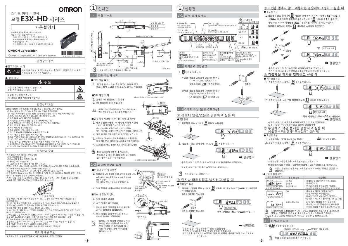
1. Installation Guide
1-1 External Dimensions
Diagram showing dimensions of the E3X-HD unit. Key dimensions include height, width, depth, and mounting hole details. Wire colors and functions are indicated: Brown for DC 12-24V, Black for Output, Blue for 0V.
1-2 Amplifier Unit Installation
Mounting on DIN Rail:
- Hook the fiber unit insertion side onto the claw and push until it locks with a click.
Removing from DIN Rail:
- Push the main unit in direction 1.
- Lift in direction 2.
Connecting Units (for Connector Type):
- Mount amplifier units one by one onto the DIN rail and connect the connectors until they click. Use model E3X-CN11 (Master Connector) for the master unit and model E3X-CN12 (Slave Connector) for the slave unit. Up to 16 units can be connected.
Safety Precautions:
- Use within the rated voltage range. Do not use AC power.
- Do not use in environments with flammable or explosive gases, or where exposed to water, oil, chemicals, or steam.
- Avoid locations with strong electric or magnetic fields.
- Do not disassemble, repair, or modify the product.
- Do not apply voltage or current exceeding the rated values.
- Do not use in ambient conditions or environments exceeding the rated values.
- Ensure correct wiring, especially for power polarity.
- Do not use if the case is damaged.
- Dispose of as industrial waste.
- The sensor surface may become hot depending on operating conditions (ambient temperature, power voltage, etc.). Handle with care during operation or cleaning.
- Separate wiring for high-voltage lines, power lines, and the product's wiring.
- Ensure safety by stopping equipment before sensor setup.
- Avoid installation in direct sunlight, humid areas prone to condensation, areas with corrosive gases, or areas with vibrations or shocks exceeding rated values.
- Extension cords should not exceed 100m. Use cords of 0.3mm² or larger for extensions.
- Limit force applied to the cord: Tension below 40N, Torque below 0.1 N·m, Pressure below 20N, Bending below 3kg.
- Detection is possible after 200ms from power ON. If the load and the product are separate, ensure the product's power is turned on first.
- For connector type, attach protective caps (included with E3X-CN series connectors) to unused power terminals to prevent electric shock or short circuits.
- A power pulse may occur when power is cut off. Turn off the power to the load or load line first.
- Excessive sensor light may cause malfunction due to insufficient mutual interference prevention. In such cases, set a wider limit.
- Always turn off the power when attaching, detaching, or expanding amplifiers.
- Do not apply excessive force (pulling or compressing) to the fiber unit while it is fixed to the amplifier unit (below 9.8N).
- Mobile Console models E3X-MC11, E3X-MC11-SV2, E3X-MC11-S cannot be used.
- Mutual interference prevention does not function with models E3X-DA-N/SD/NA. It functions with models E3X-DA-S/MDA.
- Always use with the protective cover attached.
- Communication unit models E3X-DRT21-S, E3X-CRT, E3X-ECT cannot be used.
- Do not use thinner, benzene, acetone, kerosene, etc., for cleaning.
Package Contents:
- 1 Amplifier Unit
- 1 User Manual (this document) (Japanese, English, Chinese)
1-3 Fiber Unit Installation
Using the Fiber Cutter (Model E39-F4):
- Insert the fiber unit into the fiber cutter hole. For standard fiber units, insert to the desired cutting position. For fine fiber units, insert fully.
- Press down firmly on the blade to cut.
Installing the Fiber Unit:
- Open the protective cover.
- Raise the lock lever.
- Insert the fiber unit fully into the amplifier unit's insertion port.
- Turn the lock lever back to its original position to secure the fiber unit.
CHECK!
- When attaching a coaxial reflective fiber unit to the main unit, attach the single-core fiber unit to the upper side (light emission) of the mounting hole and the multi-core fiber unit to the lower side (light reception).
2. Setup Guide
2-1 Operation and Display Summary
Diagram illustrating the various buttons and indicators on the amplifier unit:
- [L/D Indicator]: Displays Light ON/Dark ON setting status.
- [OUT Indicator]: Lights up when the output is ON.
- [ST Indicator]: Lights up during Smart Tuning.
- [TUNE] Button: Used for sensitivity adjustment.
- [UP/DOWN] Buttons: Adjust the limit value.
- [MODE] Button: Switches between setting mode and detection mode (press and hold for 3 seconds).
- [L/D] Button: Switches between Light ON and Dark ON (press and hold for 7 seconds to reset settings).
- [DPC Indicator]: Lights up when Dynamic Power Control is active.
- Digital Displays: Show light reception levels and limit values.
2-2 Control Output Switching Method
Use the [L/D] button to switch between Light ON and Dark ON modes.
- For Through-beam sensors: To turn ON when the object is present, set to "Dark ON". The [L/D Indicator] lights up.
- For Reflective sensors: To turn ON when the object is present, set to "Light ON". The [L/D Indicator] lights up.
2-3 Smart Tuning [Simple Sensitivity Adjustment]
Smart Tuning Error Messages:
| Error Name/Display/Cause | Corresponding Tuning | Countermeasure |
|---|---|---|
| Near Error (Err Err) | 2-point Tuning | Change detection function to slow response mode. Narrow the light emission/reception distance (through-beam). Bring the sensor closer to the workpiece (reflective). Increase Power Tuning level. Use fine fiber. |
| Over Error (auer Err) | 1-point Tuning, Position Tuning | Widen the light emission/reception distance (through-beam). Move the sensor away from the workpiece (reflective). Decrease Power Tuning level. |
| Low Error (Lo Err) | Full Auto Tuning, Max Sensitivity Tuning | Narrow the light emission/reception distance (through-beam). Move the sensor closer to the workpiece (reflective). Decrease Power Tuning level. |
| All (except Max Sensitivity Tuning) | Narrow the light emission/reception distance (through-beam). Move the sensor closer to the workpiece (reflective). |
The adjustment range for Smart Tuning is approximately 20 to 1/100. When selecting the "Giga Mode" detection function, the initial value is large, resulting in an adjustment range of approximately 2 to 1/100. Refer to "⑤ Detailed Setup" to change the Power Tuning level.
1. When detecting presence/absence of an object:
- 2-point Tuning: Press the [TUNE] button once with the object present and once without the object. The [ST Indicator] will light up.
- Power Tuning: Adjusts the maximum light reception to the Power Tuning level. Sets the limit value to the midpoint between maximum and minimum light reception.
- Position Tuning: Press the [TUNE] button with no object present. Then, place the object at the desired position and press and hold the button. The red digital display changes from [2Pnt] to [Po5]. Sets light reception to half of the light reception in step 1. Sets the limit value to the same value as the light reception in step 2.
- Full Auto Tuning: Press and hold the [TUNE] button with no object present until [IPnt]→[FULL]→[Auto] is displayed on the red digital display. Pass the object through the sensor (keep pressing the [TUNE] button while the object passes; release the button when [Auto] is displayed). This takes over 7 seconds. Sets light reception to half of the light reception in step 1. Sets the limit value to the midpoint between the light reception in step 1 and step 2.
- Percent Tuning: In setting mode, turn Percent Tuning ON. Press the [TUNE] button again with no object present. Sets light reception to the larger of the two light reception values (from steps 1 and 2). Sets the limit value to the midpoint between the light reception values of steps 1 and 2.
- Max Sensitivity Tuning: Press the [TUNE] button more than 3 times with the object present (through-beam) or absent (reflective) until [st FULL] is displayed, then release. Sets light reception to the light reception value in step 2. Sets the limit value to [Light reception value of step 2 * Percent Tuning level + Light reception value of step 2].
2. When you want to prevent dust or dirt:
- Percent Tuning: Set Percent Tuning ON in setting mode. Press the [TUNE] button again with no object present. Sets light reception to the larger of the two light reception values (from steps 1 and 2). Sets the limit value to the midpoint between the light reception values of steps 1 and 2.
3. When the object is moving without stopping the line:
- Full Auto Tuning: Press and hold the [TUNE] button with no object present until [IPnt]→[FULL]→[Auto] is displayed on the red digital display. Pass the object through the sensor (keep pressing the [TUNE] button while the object passes; release the button when [Auto] is displayed). This takes over 7 seconds. Sets light reception to half of the light reception in step 1. Sets the limit value to the midpoint between the light reception in step 1 and step 2.
4. When you want to determine the object's position:
- Position Tuning: Press the [TUNE] button with no object present. Then, place the object at the desired position and press and hold the button. The red digital display changes from [2Pnt] to [Po5]. Sets light reception to half of the light reception in step 1. Sets the limit value to the same value as the light reception in step 2.
5. When you want to detect transparent objects and small objects (set limit value by light reception ratio):
- Percent Tuning: In setting mode, turn Percent Tuning ON. Press the [TUNE] button again with no object present. Sets light reception to the larger of the two light reception values (from steps 1 and 2). Sets the limit value to the midpoint between the light reception values of steps 1 and 2.
2-4 Fine Limit Adjustment
Use the [UP/DOWN] buttons to adjust the limit value. Pressing and holding the buttons allows for high-speed adjustment.
- For single-core fiber: Sets light reception to "0" for the light reception value in step 1. Sets the limit value to approximately 7% of the light reception value in step 1. This is set to the minimum value for the output to turn ON correctly when the light reception value in step 1 is small, such as in long-distance detection.
- For multi-core fiber: Sets light reception to "0" for the light reception value in step 1. Sets the limit value to approximately 7% of the light reception value in step 1.
CHECK!
- If Percent Tuning is set, Smart Tuning other than Power Tuning cannot be executed.
3. Advanced Setup
3-1 Setting Mode Details
Diagrams and explanations for various advanced settings:
- Sensitivity Adjustment: Adjusts the sensitivity level.
- Response Time: Sets the response time for detection.
- Output Mode: Selects Light ON or Dark ON.
- Timer Function: Configures timer settings (e.g., ON-delay, OFF-delay).
- DPC (Dynamic Power Control): Optimizes sensor output based on workpiece conditions.
- Key Lock: Locks the buttons to prevent accidental changes.
- Reset: Resets settings to factory defaults.
3-2 Initializing Settings
To initialize settings, press and hold the [MODE] button for over 7 seconds.
3-3 Setting the Output Mode
Use the [L/D] button to switch between Light ON and Dark ON.
3-4 Setting the Timer Function
Details on configuring timer functions.
3-5 Setting DPC
Details on configuring the DPC function.
3-6 Key Lock and Reset
Key Lock: Press and hold the [MODE] and [UP] buttons simultaneously for 3 seconds to enable/disable key lock.
Reset: Press and hold the [MODE] button for over 7 seconds to reset all settings to factory defaults.
4. Troubleshooting
4-1 Common Issues and Solutions
Issue: Sensor does not detect objects.
- Check wiring and power supply.
- Ensure the object is within the detection range.
- Adjust sensitivity or use Smart Tuning.
- Clean the sensor lens.
Issue: Output is unstable or intermittent.
- Check for environmental factors like vibration or dust.
- Ensure proper mounting and alignment.
- Adjust sensitivity or use Smart Tuning.
- Check for interference from other sensors or light sources.
Issue: Error indicators are lit.
- Refer to the "Smart Tuning Error Messages" section for specific error codes and solutions.
4-2 Error Codes and Meanings
Table listing error codes (e.g., Err Err, auer Err, Lo Err) and their corresponding causes and countermeasures.
4-3 Resetting the Sensor
Press and hold the [MODE] button for over 7 seconds to reset all settings.
4-4 Checking Connections
Verify all connections are secure and correctly wired.
5. Detailed Specifications
5-1 Electrical Characteristics
Table detailing voltage, current consumption, output type, response time, and other electrical specifications.
5-2 Environmental Specifications
Table detailing operating temperature, storage temperature, ambient humidity, and resistance to shock and vibration.
5-3 Mechanical Characteristics
Table detailing dimensions, weight, and materials.
5-4 Ordering Information
List of available models and their specifications.
5-5 Accessories
List of compatible accessories, such as mounting brackets and fiber units.
User Precautions
General Precautions:
- Read and understand this manual before use.
- Keep the manual accessible for future reference.
- Ensure the product is used by qualified personnel.
Handling Precautions:
- Avoid dropping or applying strong impact to the product.
- Do not expose the product to water or excessive moisture.
- Use the product within the specified temperature and humidity ranges.
- Ensure proper ventilation around the product.
Electrical Precautions:
- Connect the power supply according to the specifications.
- Ensure proper grounding.
- Disconnect the power supply before performing any wiring or maintenance.
Maintenance:
- Clean the product regularly with a soft, dry cloth.
- Do not use solvents or abrasive cleaners.
Disposal:
- Dispose of the product in accordance with local regulations for electronic waste.
