File info: application/pdf · 4 pages · 528.70KB
Bose Panaray Sound System (502 A, 502B, 502C)
The 502A Controlled Array is a mid-high frequency component of the Bose. Panaray system. It features five new- design 4.5" (11.4 cm) helical voice coil drivers ...
Full PDF Document

If the inline viewer fails, it will open the original document in compatibility mode automatically. You can also open the file directly.
Extracted Text
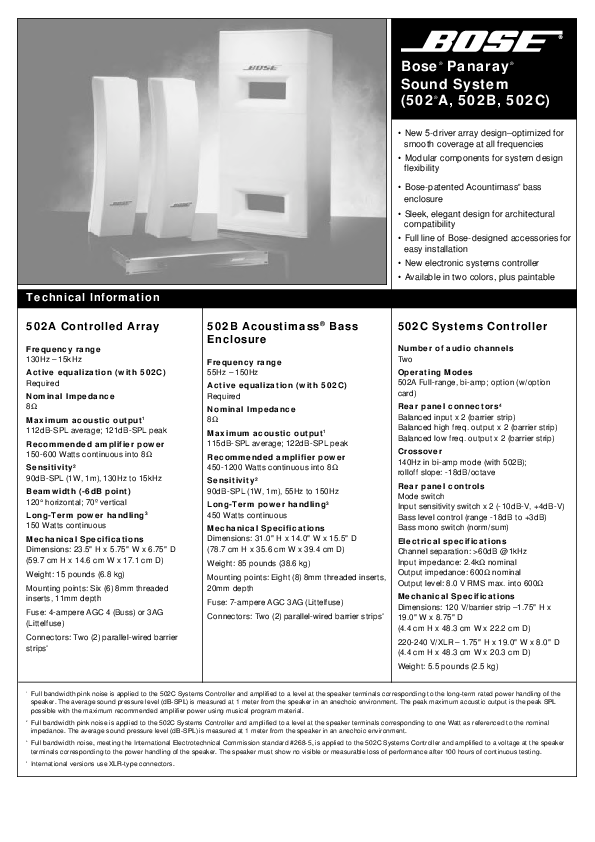
Bose� Panaray� Sound System (502�A, 502B, 502C)

Technical Information

� New 5-driver array design�optimized for smooth coverage at all frequencies
� Modular components for system design flexibility
� Bose-patented Acountimass� bass enclosure
� Sleek, elegant design for architectural compatibility
� Full line of Bose-designed accessories for easy installation
� New electronic systems controller � Available in two colors, plus paintable

502A Controlled Array
Frequency range 130Hz � 15kHz Active equalization (with 502C) Required
Nominal Impedance 8 Maximum acoustic output1 112dB-SPL average; 121dB-SPL peak
Recommended amplifier power 150-600 Watts continuous into 8 Sensitivity2 90dB-SPL (1W, 1m), 130Hz to 15kHz
Beamwidth (-6dB point) 120� horizontal; 70� vertical Long-Term power handling3 150 Watts continuous
Mechanical Specifications Dimensions: 23.5" H x 5.75" W x 6.75" D (59.7 cm H x 14.6 cm W x 17.1 cm D)
Weight: 15 pounds (6.8 kg)
Mounting points: Six (6) 8mm threaded inserts, 11mm depth
Fuse: 4-ampere AGC 4 (Buss) or 3AG (Littelfuse)
Connectors: Two (2) parallel-wired barrier strips4

502B Acoustimass� Bass Enclosure
Frequency range 55Hz � 150Hz Active equalization (with 502C) Required Nominal Impedance 8 Maximum acoustic output1 115dB-SPL average; 122dB-SPL peak Recommended amplifier power 450-1200 Watts continuous into 8 Sensitivity2 90dB-SPL (1W, 1m), 55Hz to 150Hz Long-Term power handling3 450 Watts continuous Mechanical Specifications Dimensions: 31.0" H x 14.0" W x 15.5" D (78.7 cm H x 35.6 cm W x 39.4 cm D)
Weight: 85 pounds (38.6 kg)
Mounting points: Eight (8) 8mm threaded inserts, 20mm depth
Fuse: 7-ampere AGC 3AG (Littelfuse)
Connectors: Two (2) parallel-wired barrier strips4

502C Systems Controller
Number of audio channels Two
Operating Modes 502A Full-range, bi-amp; option (w/option card)
Rear panel connectors4 Balanced input x 2 (barrier strip) Balanced high freq. output x 2 (barrier strip) Balanced low freq. output x 2 (barrier strip)
Crossover 140Hz in bi-amp mode (with 502B); rolloff slope: -18dB/octave
Rear panel controls Mode switch Input sensitivity switch x 2 (-10dB-V, +4dB-V) Bass level control (range -18dB to +3dB) Bass mono switch (norm/sum)
Electrical specifications Channel separation: >60dB @ 1kHz Input impedance: 2.4k nominal Output impedance: 600 nominal Output level: 8.0 V RMS max. into 600
Mechanical Specifications Dimensions: 120 V/barrier strip �1.75" H x 19.0" W x 8.75" D (4.4 cm H x 48.3 cm W x 22.2 cm D)
220-240 V/XLR � 1.75" H x 19.0" W x 8.0" D (4.4 cm H x 48.3 cm W x 20.3 cm D)
Weight: 5.5 pounds (2.5 kg)

1 Full bandwidth pink noise is applied to the 502C Systems Controller and amplified to a level at the speaker terminals corresponding to the long-term rated power handling of the speaker. The average sound pressure level (dB-SPL) is measured at 1 meter from the speaker in an anechoic environment. The peak maximum acoustic output is the peak SPL possible with the maximum recommended amplifier power using musical program material.
2 Full bandwidth pink noise is applied to the 502C Systems Controller and amplified to a level at the speaker terminals corresponding to one Watt as referenced to the nominal impedance. The average sound pressure level (dB-SPL) is measured at 1 meter from the speaker in an anechoic environment.
3 Full bandwidth noise, meeting the International Electrotechnical Commission standard #268-5, is applied to the 502C Systems Controller and amplified to a voltage at the speaker terminals corresponding to the power handling of the speaker. The speaker must show no visible or measurable loss of performance after 100 hours of continuous testing.
4 International versions use XLR-type connectors.

System Description
The Bose� Panaray� Sound System is a fully modular system which represents significant advances in loudspeaker array, low frequency transducer, and system control technology. The basic Panaray system consists of two 502�A controlled arrays, one 502B Acoustimass� bass enclosure, and one 502C system controller, and provides up to 122dB peak SPL (at 1 meter, driven with maximum recommended amplifier power) over the 55Hz to 15kHz range.
Extensive research has yielded new technology in array design which, using a proprietary arrangement of Bose 4.5 inch full range drivers, results in tightly controlled horizontal and vertical beamwidth, and extemely smooth bandto-band directivity. The system also features a new, compact low frequency enclosure using Bose-patented Acoustimass technology. The Panaray sound system is a highly aesthetic voice or music sound reinforcement system for permanent audio installations in theaters, auditoriums, churches, nightclubs, transportation facilities, and other places where people gather to be entertained, enlightened, or informed.
Component Description
The 502A Controlled Array is a mid-high frequency component of the Bose Panaray system. It features five newdesign 4.5" (11.4 cm) helical voice coil drivers in a slim, elegantly-designed enclosure. The result is natural sounding, extremely even coverage at all frequencies over the entire listening area. It can be used either with the 502B Acoustimass bass enclosure for full frequency sound reinforcement, or separately for voice-only reinforcement systems. The

Beamwidth* (-6 dB point)

300�
200�
nominal horizontal 100�
80� nominal vertical 60�
40� 30�
20�

10� 100

500

1,000

5,000

Beamwidth* vs. Frequency of 502A Controlled Array

10,000 Frequency [Hz]

* Beamwidth is the -6dB point, in each one-third octave band, on a polor plot representing the average within ten degrees of the horizontal and vertical planes about the array.

502A array is designed for installability in a variety of configurations, using its integral 10x safety-rated attachment points and Bose suspension and mounting accessories. The baffle and rear panel are constructed of high strength structural foam, and the speaker grille is constructed of a durable perforated steel. It is available in both Professional Gray and Arctic White, and both the enclosure and grille are fully paintable to match interior decor.
The 502B Acoustimass bass enclosure uses a single high power handling, high reliability 12" (30 cm) woofer. This new Bose-designed low frequency transducer features a high temperature 4" (10.2 cm) voice coil, cast aluminum basket, and a high durablility rubber surround. The 502B provides clear, deep bass reinforcement from a small enclosure, as a result of Bose-patented Acoustimass speaker technology. Its low crossover frequency results in a non-localizable sound source, which allows it to be unobtrusively installed apart from the 502A arrays. The enclosure is fitted with 10x safety-rated attachment points (top and bottom) for mounting in a variety of orientations.

Two-point suspension is easy to accomplish using the Bose CSB-5B suspension bracket. The 502B is available in both Professional Gray and Arctic White, and is covered with a scratch resistant vinyl, which can be painted to match any decor.
The 502C systems controller is a single rack space device which provides cross-over functions, active electronic equalization, and dual channel signal processing for both the 502A and 502B. It features -10/+4dB-V input sensitivity switches, all-balanced inputs and outputs, -18/+3dB bass level control, bass mono sum switch, automatic output muting on turn-off, and a secure, rear-panel operating mode switch.
An optional plug-in card is available for the 502C which allows 502A controlled arrays to be combined in a sound system design with the Bose Acoustic Wave� Cannon system.
The Panaray system includes a complete line of accessories for suspending or mounting both the 502A and 502B in a wide variety of configurations.

100

Directivity (Q)*
10

1 100

500

1,000

Directivity vs. Frequency of 502A Controlled Array

5,000

10,000
Frequency [Hz]

* Directivity is the ratio, in each one-third octave band, of the average response in the nominal 120� x 70� polar window, to the average response over the entire solid angle about the source.

System Configurations
The Bose� Panaray� system provides a flexible, building-block approach to fit the sound reinforcement requirements of many types of applications, from night clubs to cathedrals. Detailed installation and system design guidelines for the Panaray System are provided in the Panaray System Owner's Guide. For illustrative purposes, here are some typical system configurations.
Figure 1 shows a block diagram of the basic Panaray System, consisting of one 502�B, two 502A's, one 502C, and three channels of amplication for a stereo system. This system provides 115dB SPL @ 1 m average acoustic output. Additional low frequency output can easily be achieved by locating the cabinet against large hard surfaces. (There is also bass volume adjustment possible through the rear-panel control on the 502C).
Figure 2 illustrates how components can be added to the basic Panaray system to achieve a variety of SPL or coverage requirements. One example of an expanded system would be a small disco dance area. In this application, four arrays at the outer corners of the dance floor, plus two 502B's on the floor adjacent to the dance area, will deliver approximately 118dB SPL average, with 130dB SPL peaks, all components driven at maximum recommended amplifier power.
Figure 3 shows how the Panaray components can be interconnected for a voiceonly paging system. This system is ideal for applications where voice reinforcement is needed over a large area, such as an airport terminal or a train station. Through the use of the Bose CVT-5 constant voltage transformer, multiple 502A's can be installed in a 70/100V constant voltage distributed system. (This system operates from 130Hz and above only, and is not recommended for use where music is an integral part of the program material).

. .
.

.. ..
..

. .
.

Figure 1: Basic Panaray system

502 C

Amplifier

From Preamplifier
L

REFER TO YOUR INSTRUCTION MANUAL FOR PROPER INSTALLATION AND OPERATING PROCEDURES. INCORRECT WIRING MAY RESULT IN

CAUTION

AV I S

RISK ODFOENLOECT TORPIECNAL SHOCK RISQUNEEDPEACSHOOUCVERLIRECTRIQUE

WA R N I N G : TO REDUCE THE RISK OF FIRE OR ELECTRICAL SHOCK DO NOT EXPOSE THIS EQUIPMENT TO RAIN OR MOISTURE.

MODE SWITCH GUIDE

POSITION

OPERATING MODE

4

2-WAY WITH LOW FREQUENCY OPTION

3

(NOT USED)

2

STANDARD 2-WAY (WITH 502B)

1

VOICE ONLY/FULL RANGE (WITH 502A)

INPUT LEVEL

�10

+4

SER. NO.

D.O.M.

INPUT CH 1

CH 2

INPUT LEVEL

�10

+4

MODE
4 3
21

PROTECTED BY U.S. PATENT 3,038,964

HIGH FREQ OUTPUT

CH 1

CH 2

LOW FREQ
LEVEL .. 0

.

-18

+3

OUTPUT MODE

NORM

SUM

BOSE CORPORATION, FRAMINGHAM, MA 01701-9168 ENGINEERED AND MANUFACTURED IN U.S.A.

R

LOW FREQ OUTPUT

CH 1

CH 2

230V~AC 50/60Hz 12W

Low Frequency

Output

INPUT B

INPUT A

INPUT B

INPUT A

BRIDGE

220 V~

MADE IN

USA

CAUTION In order to grant a secure operation do not mount the amplifier in a fully closed housing. To preven electric shock, do not remove cover. Disconnect power line in case of servicing. ACHTUNG: Um sichere Funktion zu gew�hrielsten, Ger�t nicht in vollst�ndig geshlossenes Geh�use einbauen. Abdeckung w�hrend des Betriebes nicht entfernen. Bor Offnen des Ger�tes Netzstecker ziehen. Bose Corporation, Framinhman 01701, Mass, U.S.A.
Serial No.: Made in Germany

High Frequency Output

L R

INPUT B

INPUT A

INPUT B

INPUT A

BRIDGE

220 V~

MADE IN

USA

CAUTION In order to grant a secure operation do not mount the amplifier in a fully closed housing. To preven electric shock, do not remove cover. Disconnect power line in case of servicing. ACHTUNG: Um sichere Funktion zu gew�hrielsten, Ger�t nicht in vollst�ndig geshlossenes Geh�use einbauen. Abdeckung w�hrend des Betriebes nicht entfernen. Bor Offnen des Ger�tes Netzstecker ziehen. Bose Corporation, Framinhman 01701, Mass, U.S.A.
Serial No.: Made in Germany

L

ON OFF

OUTPUT B BRIDGE OUTPUT OUTPUT A

ON OFF

OUTPUT B BRIDGE OUTPUT OUTPUT A

Amplifier R

502B
502A (Right)
� �
502A (Left)

� �

Figure 2: Expanded Panaray system

502 C

REFER TO YOUR INSTRUCTION MANUAL FOR PROPER INSTALLATION AND OPERATING PROCEDURES. INCORRECT WIRING MAY RESULT IN

CAUTION

AV I S

RISK ODFOENLOECT TORPIECNAL SHOCK RISQUNEEDPEACSHOOUCVERLIRECTRIQUE

WA R N I N G : TO REDUCE THE RISK OF FIRE OR ELECTRICAL SHOCK DO NOT EXPOSE THIS EQUIPMENT TO RAIN OR MOISTURE.

MODE SWITCH GUIDE

POSITION

OPERATING MODE

4

2-WAY WITH LOW FREQUENCY OPTION

3

(NOT USED)

2

STANDARD 2-WAY (WITH 502B)

1

VOICE ONLY/FULL RANGE (WITH 502A)

INPUT LEVEL

�10

+4

SER. NO.

D.O.M.

INPUT CH 1

CH 2

INPUT LEVEL

�10

+4

MODE
4 3
21

PROTECTED BY U.S. PATENT 3,038,964

HIGH FREQ OUTPUT

CH 1

CH 2

LOW FREQ
LEVEL .. 0

.

-18

+3

OUTPUT MODE

NORM

SUM

BOSE CORPORATION, FRAMINGHAM, MA 01701-9168 ENGINEERED AND MANUFACTURED IN U.S.A.

LOW FREQ OUTPUT

CH 1

CH 2

230V~AC 50/60Hz 12W

502B

Bass Amplifier

INPUT B

INPUT A

INPUT B

INPUT A

BRIDGE

220 V~

MADE IN

USA

CAUTION In order to grant a secure operation do not mount the amplifier in a fully closed housing. To preven electric shock, do not remove cover. Disconnect power line in case of servicing. ACHTUNG: Um sichere Funktion zu gew�hrielsten, Ger�t nicht in vollst�ndig geshlossenes Geh�use einbauen. Abdeckung w�hrend des Betriebes nicht entfernen. Bor Offnen des Ger�tes Netzstecker ziehen. Bose Corporation, Framinhman 01701, Mass, U.S.A.
Serial No.: Made in Germany

ON OFF

OUTPUT B BRIDGE OUTPUT OUTPUT A

502B

INPUT B

INPUT A

INPUT B

INPUT A

BRIDGE

220 V~

MADE IN

USA

CAUTION In order to grant a secure operation do not mount the amplifier in a fully closed housing. To preven electric shock, do not remove cover. Disconnect power line in case of servicing. ACHTUNG: Um sichere Funktion zu gew�hrielsten, Ger�t nicht in vollst�ndig geshlossenes Geh�use einbauen. Abdeckung w�hrend des Betriebes nicht entfernen. Bor Offnen des Ger�tes Netzstecker ziehen. Bose Corporation, Framinhman 01701, Mass, U.S.A.
Serial No.: Made in Germany

High Frequency Amplifier One

502A

ON

INPUT B

INPUT A

OUTPUT B BRIDGE OUTPUT OUTPUT A

� �
OFF

INPUT B

INPUT A

BRIDGE

INPUT B

INPUT A

INPUT B

INPUT A

BRIDGE

220 V~

MADE IN

USA

CAUTION In order to grant a secure operation do not mount the amplifier in a fully closed housing. To preven electric shock, do not remove cover. Disconnect power line in case of servicing. ACHTUNG: Um sichere Funktion zu gew�hrielsten, Ger�t nicht in vollst�ndig geshlossenes Geh�use einbauen. Abdeckung w�hrend des Betriebes nicht entfernen. Bor Offnen des Ger�tes Netzstecker ziehen. Bose Corporation, Framinhman 01701, Mass, U.S.A.
Serial No.: Made in Germany

ON OFF

OUTPUT B BRIDGE OUTPUT OUTPUT A

High Frequency Amplifier Two

502A
� �
502A
� �
502A

Figure 3: Distributed voice-only system
502 C

REFER TO YOUR INSTRUCTION MANUAL FOR PROPER INSTALLATION AND OPERATING PROCEDURES. INCORRECT WIRING MAY RESULT IN

CAUTION

AV I S

RISK ODFOENLOECT TORPIECNAL SHOCK RISQUNEEDPEACSHOOUCVERLIRECTRIQUE

WA R N I N G : TO REDUCE THE RISK OF FIRE OR ELECTRICAL SHOCK DO NOT EXPOSE THIS EQUIPMENT TO RAIN OR MOISTURE.

MODE SWITCH GUIDE

POSITION

OPERATING MODE

4

2-WAY WITH LOW FREQUENCY OPTION

3

(NOT USED)

2

STANDARD 2-WAY (WITH 502B)

1

VOICE ONLY/FULL RANGE (WITH 502A)

INPUT LEVEL

�10

+4

SER. NO.

D.O.M.

INPUT CH 1

CH 2

INPUT LEVEL

�10

+4

MODE
4 3
21

PROTECTED BY U.S. PATENT 3,038,964

HIGH FREQ OUTPUT

CH 1

CH 2

LOW FREQ
LEVEL .. 0

.

-18

+3

OUTPUT MODE

NORM

SUM

BOSE CORPORATION, FRAMINGHAM, MA 01701-9168 ENGINEERED AND MANUFACTURED IN U.S.A.

LOW FREQ OUTPUT

CH 1

CH 2

230V~AC 50/60Hz 12W

From

� �

Constant-Voltage

INPUT B

INPUT A

INPUT B

INPUT A

BRIDGE

220 V~

MADE IN

USA

CAUTION In order to grant a secure operation do not mount the amplifier in a fully closed housing. To preven electric shock, do not remove cover. Disconnect power line in case of servicing. ACHTUNG: Um sichere Funktion zu gew�hrielsten, Ger�t nicht in vollst�ndig geshlossenes Geh�use einbauen. Abdeckung w�hrend des Betriebes nicht entfernen. Bor Offnen des Ger�tes Netzstecker ziehen. Bose Corporation, Framinhman 01701, Mass, U.S.A.
Serial No.: Made in Germany

ON OFF

OUTPUT B BRIDGE OUTPUT OUTPUT A

CVT-5
502A
� �

High Frequency

CVT-5

CVT-5
502A
� �

502A
� �

CVT-5
502A
� �

Panaray� Accessories
A full line of accessories has been specially designed by Bose� for use with the Panaray system components. These accessories increase system configuration flexibility and provide simple solutions for typical installation challenges.
502�A Controlled Array Accessories � CSB-5A Suspension Bracket (2-point gravitational type, 0��45� pitch range) � WCB-5 U-bracket (for wall/ceiling surface mounting, �90� range) � WBP-5 Bi-Pivot Bracket (single-point surface mount, 0��45� pitch, �80� yaw) � CVT-5 Constant Voltage Transformer (70/100 volt distributed system transformer and housing) � PSA-5 Stand Adapter (compatible with Bose SS-5 and SS-10 stands)
502B Acoustimass� Bass Enclosure Accessories � CSB-5B Suspension Bracket (2-point gravitational type, 0��30� pitch range)
502C Systems Controller Accessories � Acoustic Wave� Cannon system option card for active equalization (not shown)
CSB-5A Suspension Bracket
WCB-5 U-bracket
WBP-5 Bi-Pivot Bracket
PSA-5 Stand Adapter

CVT-5 Constant Voltage Transformer

CSB-5B

Suspension

�

Brackets

Engineers' and Architects' Specifications
502A Controlled Array:
The mid-high frequency device shall be a multiple-driver system with matched active equalization as follows:
The transducer complement shall consist of five (5) high-sensitivity drivers of 4.5 inches (11.4 cm) diameter, mounted vertically on a single baffle assembly such that directional characteristics are optimized for smooth response.
The input connector, located on the rear of the array enclosure, shall consist of a screw-type barrier strip.
The array enclosure shall be composed of copolymer materials, with outer dimensions of 23.5" H x 5.75" W x 6.76" D (59.7 cm H x 14.6 cm W x 17.1 cm D); its weight shall be 15 lbs (6.8 kg).
The array maximum acoustic output shall be 112dB SPL from 130Hz to 15kHz, with measurements referenced to full-bandwidth pink-noise input at 1 meter at the array's rated power. Its power handling capacity shall be 150 Watts continuous referenced to IEC noise for 100 hours. The nominal horizontal beamwidth shall be 120�. The nominal vertical beamwidth shall be 70�.
The loudspeaker shall be the Bose Panaray 502A Controlled Array.

502B Acoustimass Bass Enclosure
The low frequency device shall be a dual ported highly compact enclosure with matched active equalization as follows:
The transducer complement shall consist of one (1) high power handling driver of 30 cm diameter, mounted inside an enclosure such that distortion is minimized as a result of acoustic filtering. Its operating frequency range shall be below 150Hz so that non-localizability shall allow a high degree of location placement flexibility.
The input connector, located on the rear of the enclosure, shall be a screw-type barrier strip.
The enclosure shall be made of high strength, high density resin-impregnated vinyl wrapped particle board, with outer dimensions of 31.0" H x 14.0" W x 15.5" D (78.7 cm H x 35.6 cm W x 39.4 cm D); its weight shall be 85 lbs (38.6 kg).
The bass enclosure's maximum acoustic output shall be 115dB SPL from 55Hz to 150Hz, with measurements reference to a full-bandwidth pink-noise input at 1 meter at the enclosure's rated power. Its power handling capacity shall be 450 Watts continuous referenced to IEC noise for 100 hours.
The bass enclosure shall be the Bose Panaray 502B Acoustimass Bass enclosure.
502C Systems Controller:
The array and/or bass enclosure shall be supplied with a fixed 2-channel, systems controller which provides active electronic equalization and crossover functions, to be connected before the input(s) of the system power amplifier(s).
The systems controller shall use screwtype terminal strips for balanced input and output wiring connections, and shall be rack mountable in a single space of a standard 19" equipment rack.
It shall also include an operating mode switch,input sensitivity switch, low frequency output level control, and mono sum switch.
The electronic controller shall be the Bose 502C System Controller.
Warranty Information
The Bose Panaray 502A Controlled Array and the 502B Acoustimass Bass Enclosure, are both covered by a five-year, transferable limited warranty. The Bose 502C System Controller is covered by a two-year, transferable limited warranty.
� 1995 Bose Corporation, The Mountain, Framingham, MA 01701-9168 USA JN96508 PN171946-Rev. 1