Deathskull Laboratories! - Atari Jaguar Controllers
File info: application/pdf · 2 pages · 115.67KB
Deathskull Laboratories! - Atari Jaguar Controllers
Full PDF Document

If the inline viewer fails, it will open the original document in compatibility mode automatically. You can also open the file directly.
Extracted Text
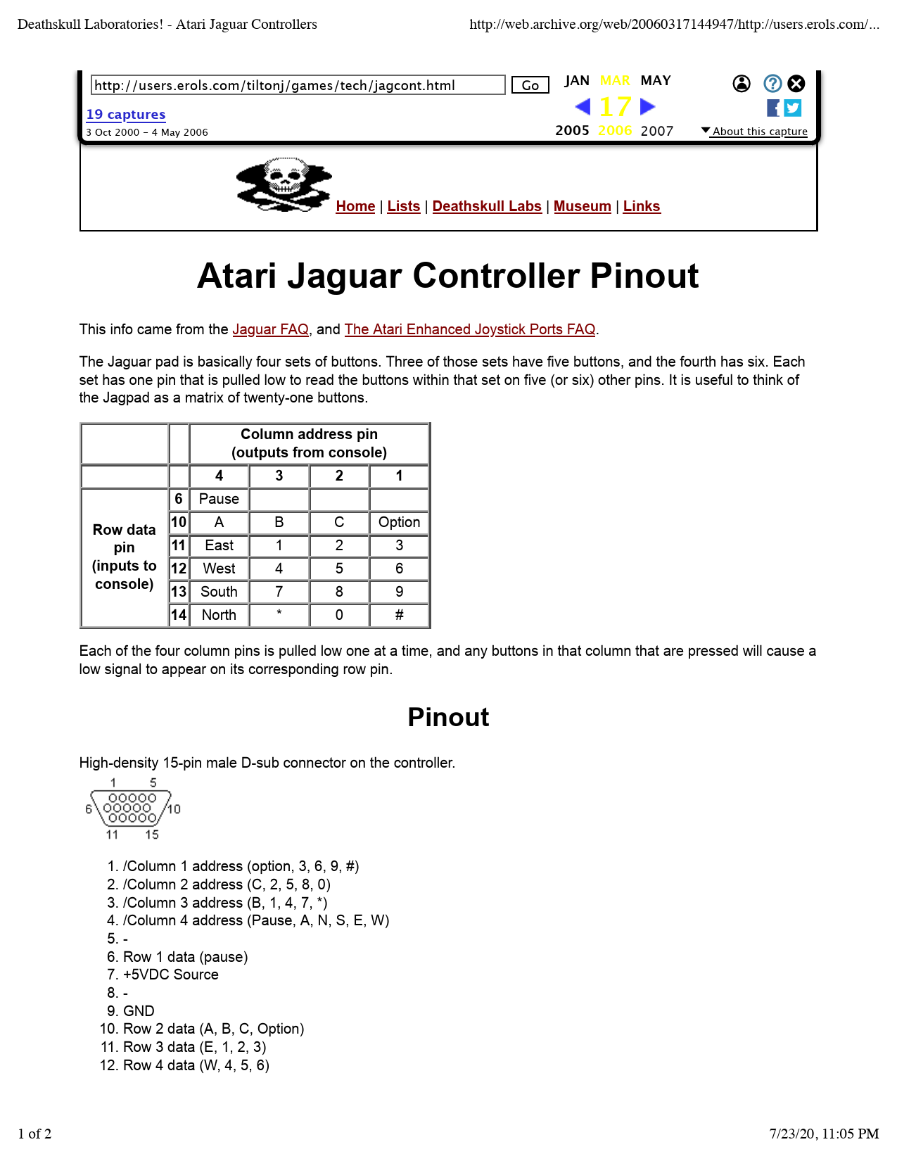
Deathskull Laboratories! - Atari Jaguar Controllers

http://web.archive.org/web/20060317144947/http://users.erols.com/...

http://users.erols.com/tiltonj/games/tech/jagcont.html
19 captures
3 Oct 2000 - 4 May 2006

Go JAN MAR MAY
17
2005 2006 2007


f
 About this capture

Home | Lists | Deathskull Labs | Museum | Links

Atari Jaguar Controller Pinout

This info came from the Jaguar FAQ, and The Atari Enhanced Joystick Ports FAQ.
The Jaguar pad is basically four sets of buttons. Three of those sets have five buttons, and the fourth has six. Each set has one pin that is pulled low to read the buttons within that set on five (or six) other pins. It is useful to think of the Jagpad as a matrix of twenty-one buttons.

Column address pin (outputs from console)

4

3

2

1

6 Pause

Row data 10 A

B

pin

11 East

1

(inputs to 12 West

4

console) 13 South

7

C Option

2

3

5

6

8

9

14 North

*

0

#

Each of the four column pins is pulled low one at a time, and any buttons in that column that are pressed will cause a low signal to appear on its corresponding row pin.

Pinout

High-density 15-pin male D-sub connector on the controller.

1. /Column 1 address (option, 3, 6, 9, #) 2. /Column 2 address (C, 2, 5, 8, 0) 3. /Column 3 address (B, 1, 4, 7, *) 4. /Column 4 address (Pause, A, N, S, E, W) 5. 6. Row 1 data (pause) 7. +5VDC Source 8. 9. GND 10. Row 2 data (A, B, C, Option) 11. Row 3 data (E, 1, 2, 3) 12. Row 4 data (W, 4, 5, 6)
1 of 2

7/23/20, 11:05 PM

Deathskull Laboratories! - Atari Jaguar Controllers

http://web.archive.org/web/20060317144947/http://users.erols.com/...

19 captures
3 Oct 2000 - 4 May 2006

Go JAN MAR MAY
17
2005 2006 2007


f
 About this capture

Team Tap

A Jagpad can only be read one column at a time, and that's done by pulling the column address pin low while leaving the other three high. Since each column address pin has two digital states, and there are four pins, you end up using only four of the total sixteen possible binary combinations of those address pins.
That's where the Team Tap comes in. Each binary combination of the four address pins corresponds to one of the four columns on one of the four controllers that can be attached.
Again, looking at it in tabular format helps. Each cell represents the console's digital output of pins 1-4 needed to address each column (1-4) of each pad (A-D).

1=high

Column

0=low 1

2

3

4

A 1110 1101 1011 0111

B 0000 0001 0010 0011 Pad
C 0100 0101 0110 1000

D 1001 1010 1100 1111

Jay Tilton 06/28/98

2 of 2

7/23/20, 11:05 PM