File info: application/pdf · 37 pages · 7.33MB
9.8kW and 10.8kW Pumped Electric Shower
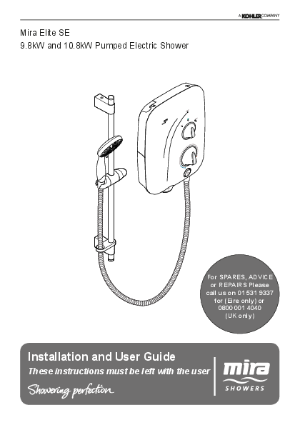
1 1383572-W2-A These instructions must be left with the user Mira Elite SE 9.8kW and 10.8kW Pumped Electric Shower Installation and User Guide For SPARES, ADVICE
Mira Elite SE Silent Pumped Electric Shower ... - Plumbworld
manual for fault diagnosis and check that it is installed and commissioned in accordance with our instructions. If this does not resolve the issue, ...
Installation and User Guide
Extracted Text
Mira Elite SE 9.8kW and 10.8kW Pumped Electric Shower

For SPARES, ADVICE or REPAIRS Please
call us on 01 531 9337 for (Eire only) or 0800 001 4040 (UK only)

Installation and User Guide
These instructions must be left with the user

1

1383572-W2-A

Important Safety Information
WARNING - This shower can deliver scalding temperatures, cause fire, electric shock or other personal injury if not operated, or maintained in accordance with the instructions, warnings and cautions contained in this guide and on the appliance.
Please read the important safety information and the operation section of this guide before using the shower. Failure to follow the instructions provided with this shower will invalidate the guarantee.
TO REDUCE THE RISK OF FIRE, ELECTRIC SHOCK OR INJURY:
1. This appliance can be used by all children and persons with reduced physical, sensory or mental capabilities or lack of experience and knowledge if they have been given supervision or instruction concerning use of the appliance in a safe way and understand the hazards involved.
2. Children shall not be allowed to play with the shower.
3. Cleaning and user maintenance shall not be made by children without supervision.
4. The outlet must not be connected to any tap or fitting other than those specified.
5. The showerhead must be descaled regularly. Any blockage of the showerhead or hose can cause damage to the shower.
6. Warning! Do not switch on if there is a possibility that the water in the heater is frozen.
7. The shower must be provided with means for local disconnection from the supply mains having a contact separation in all poles that provide full disconnection under overvoltage category III, the instructions state that means for disconnection must be incorporated in the fixed wiring in accordance with the wiring rules.
8. Installation of the shower must be carried out in accordance with these instructions by qualified, competent personnel. Read all instructions before installing the shower.
9. DO NOT switch the shower on if water starts leaking from the shower case. Isolate the electrical supply to the shower immediately.

1383572-W2-A

2

10.DO NOT switch the shower on if the case appears to be damaged or incorrectly fitted. Isolate the electrical supply to the shower immediately.
11. DO NOT increase the power setting or adjust the temperature control rapidly while using the shower.
12.DO NOT switch the shower off and back on while standing in the water flow.
13.Warning! DO NOT change the handset model. Fit only shower heads recommended by Mira and do no fit any additional device to restrict the water outlet flow.
14.When adjusting the handset mode, point handset away from body and make sure that the water temperature has stabilised before continuing to shower.
15.Use caution when altering the water temperature, always check the temperature before continuing to shower.
16.Switch the shower off at the electrical isolating switch when not in use. This is recommended with all electrical appliances.
17.Installation of the shower must be carried out in accordance with these instructions by qualified, competent personnel. Read all instructions before installing the shower.
18.Isolate the electrical and water supplies before commencing installation. The electricity must be isolated at the consumer unit and the appropriate circuit fuse removed, if applicable. Mains connections are exposed when the cover is removed.
19.DO NOT install the shower in areas with high humidity and temperature (i.e. Steam rooms and saunas).
20.DO NOT install the shower where it may be exposed to freezing conditions. Ensure that any pipework that could become frozen is properly insulated.
21.Warning! DO NOT connect the outlet of the shower to any tap, control valve, trigger operated handset or showerhead other than those specified for use with this shower as the outlet acts as a vent for the tank body. Only Kohler Mira recommended accessories should be used.

3

1383572-W2-A

22.DO NOT perform any unspecified modifications, or drill or cut holes in the product other than instructed by this guide. When servicing only use genuine Kohler Mira replacement parts.
23.Always check the water temperature is safe before entering the shower.
24.The water supplies to this product must be isolated if the product is not to be used for a long period of time. If the product or pipework is at risk of freezing during this period they should also be drained of water.
25.If the shower is dismantled during installation or servicing then, upon completion, an inspection must be made to ensure all electrical connections are tight and that there are no leaks.
26.DO NOT fit the shower to a mains water supply or where the maximum specified pressure may exceed.
27.Maximum Static Pressure is 100 kPa (1 bar).
Decommissioning and Recycling
When this appliance has reached the end of its serviceable life, it should be disposed of in a safe manner, in accordance with current local authority recycling, or waste disposal policy. For more information about recycling, please contact your local council office.

1383572-W2-A

4

Pack Contents
Pumped Electric Shower

1 x Olive 1 x Compression Nut 3 x Screws 3 x Wall Plugs

1 x Pumped Electric Shower

5

1383572-W2-A

Shower Fitting
2 x Slide Bar Support

2 x Mounting Pack

2 x Cap

1 x Slide Bar

1 x Showerhead Multimode

1 x Clamp Bracket

1 x Shower Hose 2 x Hose Seal
1 x Retaining Ring

1383572-W2-A

6

Introduction
Thank you for choosing a Mira shower. To enjoy the full potential of your new shower, please take time to read this guide thoroughly, and keep it handy for future reference. Products manufactured by Kohler Mira Ltd are designed to be safe, provided that they are installed, used and maintained in good working order, in accordance with our instructions and recommendations. Follow all warnings, cautions and instructions contained in this guide, and on, or inside the shower. This guide is also available in digital format from our website or by contacting customer services.
Products Covered

Product Variant Mira Elite SE
Mira Elite SE Dual Mira Elite SE

9.8 kW 9.8 kW 10.8 kW

Model No. J11A J11Ad J11B

Recommended Usage

Colour White Chrome White Chrome White Chrome

Domestic


Light Commercial


Heavy Commercial


Healthcare


Patents and Design Registration

Design Registration: Patents:

003617653-0006 GB 2 289 323, 2 341 667, 2 359 339, 2 427 460, 2 432 201 Ireland: 80655, 82835, 83692

7

1383572-W2-A

Specifications

Dimensions Height Width Depth

363 mm 270 mm 82 mm (110 mm including Dials)

Plumbing
Maximum Static Pressure Minimum Static Pressure Maximum Inlet Temperature Minimum Inlet Temperature Inlet Connection Maximum Water Hardness Outlet Connection

Variant 9.8 kW and 10.8 kW 100 kPa (1.0 bar) 0.8 kPa (0.008 bar)
30�C 2�C 15 mm Compression 200 ppm CaCO * 1/2" BSP Male to flexible hose

Electrical
Nominal Power at 240 V ac Nominal Power at 230 V ac Recommended MCB Rating Maximum Supply Cable Size Recommended RCD Rating Recommended Isolator Switch
Appliance Sealing Rating Maximum Ambient Temperature Minimum Ambient Temperature

Variant

9.8 kW

10.8 kW

9.8 kW

10.8 kW

9 kW

9.9 kW

40 A

45 A

16 mm�

30 mA tripping current

45 A double-pole with 3 mm contact separation

IP X4 - suitable for installation in Zone 1

30�C

2�C

* Water supplies with a water hardness above 200ppm CaCO3 should be fitted with a water softener or other scale reducing device.

1383572-W2-A

8

Guarantee
For domestic installations, Mira Showers guarantee the Mira product against any defect in materials or workmanship for a period of two years from the date of purchase (shower fittings for one year). For non-domestic installations, Mira Showers guarantee the Mira product against any defect in materials or workmanship for a period of one year from the date of purchase. For Terms and Conditions refer to the back cover of this guide.

European Conformity Information

This range of electric showers complies with the following European directives:
2014/35/EU Low Voltage Directive, 2014/30/EU EMC Directive, 2011/65/EU RoHS Directive
This range of electric showers are high power appliances and are subject to conditional connection. If the main electrical supply fuse is rated less than 80 Amps, the local electricity supply company must be contacted to confirm if the electrical supply is adequate.
This range of showers complies with the requirements of the UK's water regulations.

Eco-Design/Energy Labelling

Product Information
Indicative annual electricity consumption (kWh), based upon 2100 Wh daily water energy demand. Actual electricity consumption will depend on kW rating and the duration and frequency of use.

Load Profile Efficiency Class Efficiency (%) Daily Electricity Consumption (kWh) Annual Electricity Consumption (kWh)

Mira Elite SE

9.8 kW

10.8 kW

XS

XS

A

A

39.0

38.9

2.172

2.177

473

474

9

1383572-W2-A

Installation Requirements
Plumbing
1. The plumbing installation must comply with all national or local water regulations and all relevant building regulations, or any particular regulation or practice specified by the local water supply company.
2. The shower is designed to operate with a gravity fed water supply providing a pressure from 0.8 kPa* (0.008 bar / 80 millimetres head) to 100 kPa (1 bar / 10 metres head, the vertical distance from the base of the cold water cistern to the top of the shower unit). The shower must have its own separate supply from the cistern. DO NOT FIT THE SHOWER TO A MAINS WATER SUPPLY OR WHERE THE MAXIMUM SPECIFIED PRESSURE MAY BE EXCEEDED! Failure to comply with these restrictions may result in product damage not covered by the guarantee. * Note: In practice the minimum head required will increase with pipe length. See "Pipework" for further guidance which includes a calculation table to make sure that adequate head is available for any given installation.

25 Gallon/113 Ltr Cistern

25 mm

Correct Cistern Take Off
Positioned away from the ball valve, with a 25 mm distance from the base of the cistern. This connection will prevent air and debris entering the shower supply.

Incorrect Cistern Take Off
Debris from the bottom of the cistern and air generated when the cistern refills will enter the shower supply.

To shower unit only.

1383572-W2-A

10

3. DO NOT install the product in a position or location that will limit access for servicing.
4.A suitable position for the shower will have a minimum clear distance of 200 mm above and below the shower unit to allow for cover removal and refitting.
5. The position of the shower and shower fittings must provide a minimum air gap of 25 mm between the showerhead and the spill over level of any bath, shower tray or basin. There must be a minimum distance of 30 mm between the showerhead and the spill over lever of any toilet, bidet or other appliance with a Fluid Category 5 backflow risk.

Electric Shower

Zone of Backflow Risk

200 mm 200 mm

30 mm Minimum

25 mm Minimum

25 mm Minimum

Toilet or Bidet Bath or Shower

FC5

Tray FC3

Hand Basin FC3

Hose retaining ring fitted and shower fittings fixed at a suitable height preventing dirty water backflow

Note: There will be occasions when the hose retaining ring will not provide a suitable solution for Fluid Category 3 installations, in these instances an outlet double check valve must be fitted, this will increase the required supply pressure typically by 10kPa (0.1 bar). Double check valves fitted in the inlet supply to the appliance cause a pressure build up, which affect the maximum static inlet pressure for the appliance and must not be fitted. For Fluid category 5 double check valves are not suitable.

11

1383572-W2-A

6. The shower is suitable for installation within the shower area. The shower is fitted with an internal pressure relief valve and must be installed over a water catchment area.
7.Position the shower where the controls are at a convenient height for the user. Position the showerhead so that the water sprays in line with the bath or across the opening of a shower cubicle. The showerhead must not spray directly onto the shower unit during normal use. The installation must not cause the shower hose to be kinked during normal use.
8 The shower must be fitted to a waterproof, flat and even wall surface. The 3 screws (No.8 x 1�") and wall plugs supplied are suitable for most solid wall installations. Alternative fixing screws for panel structures are not supplied. Use all 3fixing points to secure the shower unit, be sure to use fixings appropriate for the chosen wall structure and environment.
DO NOT fit the shower to the wall and tile up to the case or seal the gap between the shower and the wall surface with sealant.
9 The shower is intended to be permanently connected to a gravity fed water supply using the inlet connection supplied as part of the shower unit.
DO NOT use any other type of fitting. 10.U se a minimum of 15 mm diameter supply pipework. For long pipe runs, this
should be increased to 22 mm (see "Pipework" for guidance and calculation table). When using flexible plastic pipe it is essential that the pipe is kept flat to minimise air build up in the system.
11. A full bore/non restrictive servicing valve must be fitted in a readily accessible position adjacent to the shower to facilitate maintenance of the shower.
DO NOT use a valve with a loose washer plate (jumper) as this can lead to a build up of static pressure.
12.The shower is not designed to be plumbed directly from the rear. For rear-entry supply, add an elbow to the supply pipe and connect as a rising or falling supply. We recommend a falling supply to prevent air lock in the pipework.
13.If pipework and/or electrical cables enter the shower from the rear through a hole in the wall, provision must be made to prevent water ingress back into the wall structure.
14. DO NOT apply excessive force to plumbing connections; always provide mechanical support when making plumbing connections. Any soldered joints should be made before connecting the shower.
15.A water treatment device should be installed where the water hardness may exceed 200ppm. Malfunctions caused by excessive limescale formation are not covered by the guarantee.
16.D O NOT perform the electrical installation until the plumbing has been completed and checked for leaks.
17. The water supplies to this product should be isolated if the product is not to be used for a long period of time. If the product or pipework is at risk of freezing during this period they should also be drained of water.

1383572-W2-A

12

Pipework
Long pipe runs and excessive use of 90� elbow fittings will significantly reduce the available head to supply the shower unit. The pipework table provided should be used to ensure that an adequate pressure is available for any given application.

A

X

B

Pipework Schematic Diagram
Use the following table to calculate the dimension (x) to give a minimum effective head of 80 mm required to produce a satisfactory shower in all conditions.
The example below is based on the "Pipework Schematic Diagram" with 15 mm pipework, A = 1.5m, B= 0.75 m.

Size

Quantity

Head Loss (mm)

15 mm Pipe

(A) 1.5 + (B) 0.75 = 2.25 x 120

270

22 mm Pipe

(A) + (B) =

x 20

15 mm Elbow

Number of Elbows 1 x 55

55

22 mm Elbow

Number of Elbows x 15

Minimum Effective Head

80

(X) mm

405

13

1383572-W2-A

Electrical
1. The electrical installation must comply with BS 7671 (commonly referred to as the IEE Wiring Regulations) and all relevant building regulations, or any particular regulation or practice specified by the local electricity supply company.
2. Ensure that all circuit protection devices, switches and cabling are adequate for the rated current of the shower and that the rating of the electricity supply company fuse and the consumer unit are adequate for the additional demand.
3.The shower must be earthed. Ensure that any supplementary bonding complies with the relevant regulations.
4. The shower is intended to be permanently connected to the fixed electrical wiring of the mains system. A separate supply must be provided from the consumer unit to the shower.
5. The shower must be provided with means for local disconnection that is incorporated into the fixed wiring in accordance with the relevant local wiring regulations. This must be a double pole switch, which has at least 3 mm contact separation in each pole. The switch can be a pull-cord type mounted to the ceiling within the shower room or a rocker type switch mounted to the wall in the applicable zone area.
6. For new installations a 30 mA Residual Current Device (RCD) must be incorporated into the electrical supply to the shower in accordance with the current wiring regulations. When replacing an existing electric shower we recommend that a 30 mA RCD is incorporated in accordance with current wiring regulations if not already provided.
7. Check all electrical connections are tight, to prevent overheating, before switching on the electrical supply.
DO NOT apply excessive force to the terminal block.
8.DO NOT supply any other electrical equipment including extractor fans or pumps via the shower unit.
9. DO NOT switch on the electrical supply until the plumbing has been completed and checked for leaks.
Consumer Unit

Shower Unit

Double Pole Isolating Switch

1383572-W2-A

Electrical Schematic Diagram
14

Shower Unit Wiring Diagram
15

L
MOTOR M N E

THERMAL SWITCH

LATCHING SWITCH

H

H

P

SOLENOID VALVE

POWER LED

P USER SELECTED FLOW / POWER SWITCH
TANK

INLET CONNECTOR

PUMP MOTOR

PUMP POWER SUPPLY

BLUE S BROWN A
GREEN B BLUE C
TERMINAL BLOCK ASSEMBLY
LEN
RED F RED E BROWN G BROWN H

BROWN P BROWN D

BROWN A

BLUE C

BLUE S

BLUE K BLUE Q
HEATER TANK ASSEMBLY

BROWN G RED F
BROWN H

LED

BLACK RED

GREY T

GREEN R

BLUE

INLET CONNECTOR ASSEMBLY

MICROSWITCHES

BROWN P

BLUE Q

BROWN D

SOLENOID

GREY T

GREY J BLUE K

LATCHING SWITCH
GREY T

BROWN D

1383572-W2-A

Install the Shower
Warning! Isolate the electrical and water supplies before installing the shower.

Decide on a suitable position for the shower unit and fittings. See "Installation - Plumbing" and seperate fittings guide if fitting dual product.

Screws
Service Bung Tunnel
Cover Outlet Bung
Screws
1383572-W2-A

Remove the four screws that holds the cover on and remove the cover. Remove the bungs. Use the installation template provided, level and mark the positions of the three fixing holes. Drill three holes to suit the fixing screws and wall plugs.
Caution! DO NOT drill into cables or pipes in the wall.
Note: Ensure that there are sufficient lengths of supply pipe and electrical cable to reach the connection points.
16

Determine the direction and route of the incoming water supply: falling (entering the shower from the top), or rising (entering the shower from the bottom).
Note: Top entry water inlets are preferable to reduce the risk of pipework airlocks.
Note: Thoroughly flush the supply pipe before connecting to the product.
Determine the direction and route of the electric supply cable.

Thinned Section

The rear case has thinned sections that can be removed to allow entry of the supply pipe and electrical cables.
Remove the top thinned section of the rear case for a falling supply, or remove the bottom thinned section at service tunnel for a rising supply.
Note: DO NOT extend beyond thinned section.

Rear Case

17

1383572-W2-A

Rotate the inlet connector to suit the direction of the incoming water supply.
Fix the shower unit to the wall, 3 x No. 8 x 1�" screws and wall plugs are supplied. See "Installation - Plumbing" for further details.

1383572-W2-A

18

Check the inlet filter is in position before connecting inlet supply.
Connect the inlet supply pipe to the inlet connector using the compression nut and olive (supplied). DO NOT use jointing pastes to make water connection.
Support the inlet connector as shown when tightening compression fitting.
Upon completion of the installation ensure connections and back case are not under any stress due to misaligned pipework or electrical cables.

Turn on the water supply and check for leaks.

Strip back sufficient outer cable insulation to enable routing to terminal block.
Fit an earth sleeve to the earth wire (not supplied).
Loosen the screws in the terminal block and insert the wires.
L (Live) = Brown Wire
(Protective Earth) = Green Sleeved Wire
N  (Neutral) = Blue Wire
Tighten the screws in the terminal block, ensure the wires are secure and tight.
Note: DO NOT exert strain on the terminal block. Make sure that the electrical connections are tightly screwed down.

19

1383572-W2-A

Ensure the earth bonding complies with relevant regulations.
Fit the service tunnel.
Ensure the control dials are aligned with the spindles and replace the cover.
Tighten the four cover screws (DO NOT use electric screwdrivers to tighten the screws).
DO NOT use alternative screws to secure the cover. This can cause internal damage to the appliance.
DO NOT seal around any part of appliance.
This completes the installation, follow the guidelines in section `COMMISSIONING' to prepare the shower for use.

1383572-W2-A

20

Install the Shower Fittings
Note: For Dual Fittings Installation please refer to the separate installation guide supplied.
�8mm
�8mm

For new installations optimum fixing centres 600mm

We recommend that the slide bar is installed with the ends flush. Mark the wall fixing positions and drill two holes to suit the wall fixings.
Caution! Do not drill into cables or pipes in the wall.
Note: For new installation optimum fixing centres 600 mm. Replacement installation fixing centres 635 mm maximum.

21

1383572-W2-A

Insert the wall plugs and fix the mounting brackets and secure with the wall screws.
Note: Check for vertical alignment before tightening. The mounting brackets are slotted to aid this alignment. Then fully tighten.

Slide Bar Support (x2) Clamp Bracket Hose Retaining Ring
Cap (x2)
1383572-W2-A

Assemble the clamp bracket, hose retaining ring, slide bar supports and caps to the slide bar.
Make sure that the wall screws are flush with the inside edge of the mounting brackets. Fit the slide bar supports over the mounting brackets, then adjust the slide bar vertically ensuring an equal length of slide bar protrudes from the top and bottom mounting bracket (or flush with the end of the slide bar for new installations).
Remove the slide bar assembly carefully, preventing any further movement between the slide bar and the slide bar supports.
Tighten the two slide bar clamping screws no more than half a turn to secure the slide bar supports to the slide bar.
Caution! Overtightening these screws will cause damage. 22

Install the slide bar assembly onto the mounting brackets. Tighten the 2 x M4 screws with the supplied 3 mm hexagonal key. Caution! DO NOT force assembly on to the mounting brackets, re-align a slide bar support if required.
Fit a hose seal into the conical nut and screw onto the outlet of the shower.
Caution! DO NOT over tighten.
Feed the hose through the retaining ring. Fit a hose seal into the conical nut and screw onto the showerhead.
Caution! DO NOT over tighten.
Place the showerhead assembly into the clamp bracket.

23

1383572-W2-A

Commissioning
Installer: Make sure you follow the commissioning procedure to check the function and performance before using the shower for the first time. Make sure that all users are familiar with the operation of the shower. Pass on this guide to the homeowner.

Turn power control to Low.

Turn temperature control to the full cold position.

Ensure electrical supply is switched off and water supply is on.

TO BLEED AIR

Turn shower off. Insert a suitable coin or an 8 mm hexagonal key into the cap and turn to the left. Remove the filter from the shower unit. Push the rod up until water flows freely. Refit the filter, turn until locked. Repeat the steps 1-3.

Place the shower hose into water catchment area. Fit the shower hose to the outlet of the shower (If installing the dual product use the short hose).

1383572-W2-A

Loosen the four screws and remove the cover.
24

Slowly rotate the bleed valve anti-clockwise until air bleeds from the pump housing. When water flows from the bleed valve this indicates that air is removed, and the pump is primed.
Important! Do not completely remove the bleed valve.
Close the bleed valve by rotating clockwise. Do not overtighten.

Switch on the electrical supply.

Fit the cover using the screws provided. DO NOT use electric screwdrivers to tighten the screws.

Push START/STOP button. Wait for full flow of water from the hose. This may take up to 30 seconds.
Note: If water does not flow ensure there are no air locks and repeat commissioning.

Depending on the fittings installed connect the hose to the handset or diverter. Operate the shower to ensure the product is working correctly. Advise the homeowner how to operate the shower.

25

1383572-W2-A

User Operation
Read the section "Important Safety Information" first.

Switch on the electrical supply.

Push START/STOP button.

Set power control to low / eco / high. Low = No heating elements turned on Eco = 1 heating element on (Summer) High =2 heating elements on (Winter) See information Effect Of Seasonal Changes.

Anti-Clockwise = Cooler

Clockwise = Warmer

Adjust showering temperature as required.

0 15

HOT COLD

Allow 10 - 15 secs for any temperature adjustments to stabilise and reach the showerhead.

Check water temperature before entering shower.

1383572-W2-A

26

Push START/STOP button. Shower Switch off the electrical supply. turns off and water flow stops.
A small amount of water may continue to drain/drip from the overhead shower or handset shower until the head is empty. ALWAYS switch the shower off at the electrical isolating switch when not in use. This is recommended with all electrical appliances.
Warning! Turning the shower off and back on during showering may result in unstable temperatures at the showerhead. Always ensure the temperature has stabilised before re-using the shower.

27

1383572-W2-A

Please note when altering the shower temperature...
CAUTION! Altering the temperature control rapidly can cause the water temperature to become briefly hotter or colder than required. For best results, adjust the temperature control a small amount and allow the temperature to stabilise. Continue to adjust until a comfortable showering temperature is reached. DO NOT increase the power setting while standing in the water flow. Avoid changing the power setting when the shower is in use, this can cause a large increase or decrease in water temperature. DO NOT switch the shower off and back on while standing in the water flow. Cycling the shower off/on may result in unstable water temperatures. Always ensure the temperature has stabilised before re-using the shower. The shower has a high performance pump installed, which has been acoustically designed for quieter performance, but may produce some noise during operation. Pump tone may change when altering temperature position.
Effect of Seasonal Changes
The temperature of the mains water feed to the cistern is not constant throughout the year, i.e. cooler during winter, warmer during summer. To maintain the desired showering temperature, adjust the power and temperature controls accordingly. The shower flow rate will adjust automatically.
HOT
COLD

For a cold shower select low.

For a summer warm shower select eco / high.

For a winter warm shower select high.

Adjust the power and temperature controls as required.

Flow rate will reduce when temperature control is increased.

1383572-W2-A

28

User Trouble Shooting

If the malfunction has not been detailed in the fault finding table or it was not possible to correct the malfunction, professional assistance may be required.

Symptom

Possible Cause

Possible Remedy

Shower fails to operate

Isolator switch in the off position
Fuse blown or MCB/RCD tripped, indicating possible electrical fault

Switch on the electrical supply via the pull cord or wall mounted switch
Renew the fuse or reset the MCB/RCD. If fault persists, contact your installer

Hose or shower head blocked. Filter Remove and clean. Check hose and replace

blocked or removed.

if necessary. Refit all parts correctly.

Water supply isolating valve set too low or turned off.

Fully open isolating valve.

Air in system.

Refer to cleaning / replacing the filter and air purge section. If this does not clear the air contact your installer and refer to commissioning section.

Low water flow. No water flow.

Insufficient water pressure or water Gravity fed system, minimum pressure 0.8

flow for shower operation.

kPa. (0.008 bar / 80mm head.)

Flow Valve faulty.

Contact your installer to replace.

Heater Tank excessively scaled.

Contact your installer to replace. Consult your installer about fitting a water softener for hard water areas.

Pump overheated or faulty.

Wait 30 minutes for pump to cool and reset automatically. If fault persists, contact your installer to replace.

Water pressure below minimum Make sure shower isolating valve is fully

required for shower operation.

turned on. Check filter for blockage and clean.

Water flow stops and motor tone increases.

Stored water is blocked or has run out.

Turn shower off immediately! Make sure there is a constant water supply when shower is in use.

Air in system.

Refer to cleaning / replacing the filter and air purge section. If this does not clear the air contact your installer and refer to commissioning section.

Water will not turn off.

Shower's Flow Valve, Solenoid or Contact your installer to replace parts as

Start/Stop switch has failed.

required.

Stored water temperature has Turn the power control to eco and readjust

increased.

the temperature control.

Unable to select a cool enough temperature.

Filter, Hose or shower head blocked.
Temperature dial in incorrect position.

Remove and clean. Check hose and replace if necessary.
Rotate temperature dial anti-clockwise until desired temperature is reached.Switch the power selector to Eco if required.

29

1383572-W2-A

Symptom

Possible Cause

Possible Remedy

Shower cycles from hot to cold.

Controls are set too high. Filter, Hose or shower head blocked.

Turn the power control to eco and readjust the temperature control.
Remove and clean. Check hose and replace if necessary.

No change in temperature of low / eco / high settings.

Shower's Flow Valve, Microswitch or Heater Tank has failed.

Contact your installer to replace parts as required.

The temperature control has little or no effect on water temperature.

Filter, Hose or shower head blocked.

Remove and clean. Check hose and replace if necessary.

Shower's Flow Valve (joined to the Contact your installer to replace parts as

Heater Tank) has failed.

required.

No hot water when set to eco / high.

Shower's Flow Valve, Microswitch or Heater Tank has failed.

Remove and descale Showerhead.

Hose kinked or blocked.

Check hose and replace if necessary.

No hot water from shower, with the knobs in any position.

Electrical supply or product problem.

Contact your installer to check installation or replace parts as required.

Note: What to do if something goes wrong. If your product does not work correctly check that it is installed and commissioned in accordance with our instructions. If this does not resolve the issue, contact us for help and advice. Refer to Customer Support page for more details.

Cleaning
Cleaning the Showerhead
Many household and commercial cleaners, including hand and surface cleaning wipes contain abrasives and chemical substances that can damage plastics, plating and printing and should not be used. These finishes should be cleaned with a mild washing up detergent or soap solution, and then wiped dry using a soft cloth.
Important! Keeping the showerhead clean and free from limescale will ensure that your shower and showerhead continue to perform to their maximum. A blocked showerhead can restrict the flow rate and may cause damage to your shower. Use your thumb or a soft cloth to wipe any limescale from the nozzles.

1383572-W2-A

30

Inspecting the Hose
Important! The shower hose should be inspected periodically for damage or internal collapse, internal collapse can restrict the flow rate from the showerhead and may cause damage to the shower.
Unscrew the hose from the showerhead and the shower outlet.
Inspect the hose.
Replace if necessary.
Warning! If you have to replace the shower fittings only use Mira Showerheads and hoses. Non-Mira manufactured showerheads and hoses can be restrictive leading to scalding temperatures or other personal injury.
Servicing
Warning! There are no user serviceable parts inside the shower. Servicing of the shower must only be carried out by qualified, competent personnel following the instructions provided in this guide and those provided with any spare part.
Cleaning / Replacing the Filter The filter can be removed from the lower left of the shower unit. Isolate the electrical supply to the shower unit before removing the filter. The water supply will shut off automatically as the filter is removed, however we recommend isolating the water supply to the shower unit to aid with refitting the filter. Note: Removing and replacing the filter allows a small amount of air into the product. The time it takes to clear the air will vary depending of the effective head of the installation.

31

1383572-W2-A

Single Outlet

Dual Outlet

Lower the handset into the water Put the divertor in handset mode

catchment area.

and lower the handset into the water

catchment area.

Insert a suitable coin or an 8 mm

Turn power control to Low.

hexagonal key into the cap and turn to

Turn temperature control to the full cold. the left.

Locked position

Rinse the filter in clean warm water removing any dirt or debris. Replace if the filter mesh is damaged. Make sure the filter is correctly refitted to the locked position.

Switch the electrical supply on and start the shower.
Run the product for 5 minutes or until full flow is restored. This will ensure all air is removed from the system.

1383572-W2-A

32

Spare Parts

1941.015

A (x4)

24V Power Supply

1746.436 Thermal Switch

1941.016

Power Supply Clamp

A (x5)

1941.014

Pump Motor Assy

A (x7)

1941.016 Motor Clamp

1845.158 Service Tunnel
1845.153 Terminal Block Assembly 1845.184
Pump Elbow (includes clips)
1845.157 Inlet Connector

1788.434

1788.429

Solenoid

On / Off Switching

Assembly

1788.433

Valve Clamp

1845.156

Filter Housing

416.38 Inlet Clamp
1845.160 Filter

1845.191 (9.8kW) 1788.428 (10.8kW) Heater Tank Assembly
1788.431 Outlet
1789.085 Latching Switch
1941.013 Cover Assembly

1941.019 Wire Loom Assembly (Not illustrated) 1845.186 Screw Pack - Components Marked `A' 1845.187 Component Pack (Not illustrated) 1746.507 Cover Seal (not shown)
33

1383572-W2-A

1740.595 Slide Bar Support (x2)

1703.194 Mounting Pack (x2)
1703.204 Slide Bar 1703.275 Clamp Bracket

1703.196 Cap (x2)
1740.615 Showerhead Multimode

1613.037

Shower Hose

632.73

(Includes x2 Hose Seals)

Hose Seal Pack

1703.449 Hose Retaining Ring

1383572-W2-A

1703.197 Soap Dish (Accessory)
34

Notes

35

1383572-W2-A

Customer Support

Guarantee Your product has the benefit of our manufacture's guarantee which starts from date of purchase. This guarantee only applies in the United Kingdom and Republic of Ireland. To activate this guarantee, please return your completed registration card, visit our website or free phone 0800 5978551 within 30 days of purchase (UK only).
Within the guarantee period we will resolve defects in materials or workmanship, free of charge, by repairing or replacing parts or product as we may choose.
This guarantee is in addition to your statutory rights and is subject to the following conditions :
 The guarantee applies solely to the original installation under normal use and to the original purchaser only. The product must be installed and maintained in accordance with the instructions given in this guide.
 Servicing must only be undertaken by us or our appointed representative. Note! If a service visit is required the product must be fully installed and connected to services.
 Repair under this guarantee does not extend the original expiry date. The guarantee on any replacement parts or product ends at the original expiry date.
 For shower fittings or consumable items we reserve the right to supply replacement parts only.
The guarantee does not cover:
 Call out charges for non product faults (such as damage or performance issues arising from incorrect installation, improper use, inappropriate cleaning, lack of maintenance, build up of limescale, frost damage, chemical attack, corrosion, system debris or blocked filters) or where no fault has been found with the product.
 Water or electrical supply, waste and isolation issues.
 Compensation for loss of use of the product or consequential or indirect loss of any kind.
 Damage or defects caused if the product is repaired or modified by persons not authorised by us or our appointed representative.
 Routine maintenance or replacement parts to repaired or modified by persons not authorised by comply with the requirements of the TMV2 or repaired or modified by persons not authorised by TMV3 healthcare schemes
 Accidental or wilful damage.  Products purchased ex-showroom display.

What to do if something goes wrong If your product does not work correctly refer to this manual for fault diagnosis and check that it is installed and commissioned in accordance with our instructions. If this does not resolve the issue, contact us for help and advice.
Helpdesk Service Contact our Customer Services Team for product advice, to purchase spare parts or accessories or to set up service visit. You can contact us via phone or e-mail - contact details below. Please provide your model name, power rating (if applicable) and date of purchase.
Mira Showers Website (www.mirashowers.co.uk) Visit our website to register your guarantee, download user guides, diagnose faults, purchase our full range of accessories and popular spares, or request a service visit.
Spares and Accessories We hold the largest stocks of genuine Mira spares and accessories.Contact us for a price or visit our website to purchase items from our accessory range and popular spares. (Only available in the United Kingdom ) Service/Repairs No one knows our products better than our nationwide team of Service Technicians. We can carry out service or repair work to your product both during and after the guarantee period. (Only available in the United Kingdom and Republic of Ireland) Ask about our fixed price service repairs. To Contact Us: UK
0800 001 4040
Fax: 01242 282595
Email � Visit www.mirashowers.co.uk/contactus
By Post: Mira Customer Services Dept, Cromwell Road, Cheltenham, Gloucestershire GL52 5EP
To Contact Us: Eire Only
01 531 9337
E-mail: CustomerServiceEire@mirashowers.com

Mira is a registered trade mark of Kohler Mira Limited.
The company reserves the right to alter product specifications without notice.
1383572-W2-A

14648
36� Kohler Mira Limited, September 2019

Check out our full range of Showers
Electric Showers Digital Showers Mixer Showers Power Showers Smart Showers Shower Towers
From Top Shower Brands
Mira Showers Aqualisa Showers Triton Showers Gainsborough Showers
Shower Pumps can upgrade your showering experience even more
Stuart Turner Shower Pumps Salamander Shower Pumps Grundfos Shower Pumps