File info: application/pdf · 78 pages · 3.28MB
INSTALLATION MANUAL
The Hx™3 Touch Screen Thermostat is designed to control conven- tional and communicating HVAC systems. Use applicable Johnson Con-.
PDF Hx™3 TOUCH SCREEN THERMOSTAT ... - Express Overstock.com
This manual contains information about setup, operation, and trouble-shooting. Short videos illustrating the installation, setup, and configura-tion of the Hx™3 Touch Screen Thermostat are available at www.simplygetting…
Full PDF Document

If the inline viewer fails, it will open the original document in compatibility mode automatically. You can also open the file directly.
Extracted Text
INSTALLATION MANUAL
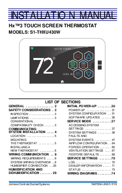
HxTM3 TOUCH SCREEN THERMOSTAT MODELS: S1-THXU430W
11/07/18 11:14AM
72�
62
Settings
Auto
85 COOL TO
.
LIST OF SECTIONS
GENERAL . . . . . . . . . . . . . . . . 2
INITIAL POWER-UP . . . . . . . .30
SAFETY CONSIDERATIONS . 2
POWER-UP . . . . . . . . . . . . . . . 31
INSPECTION . . . . . . . . . . . . . . . . 3 LIMITATIONS . . . . . . . . . . . . . . . 3 CONVENTIONAL
SYSTEM CONFIGURATION . . 31 SOFTWARE UPDATES . . . . . . 36 SERVICE MODE . . . . . . . . . . .37
COMPATIBILITY CHECK . . . . . . 3
ACCESSING SYSTEM
COMMUNICATING SYSTEM INSTALLATION . . . . 4
SETTINGS . . . . . . . . . . . . . . . . 37 SYSTEM SETTINGS . . . . . . . . 38
LOCATION . . . . . . . . . . . . . . . . . 5
FAULTS AND
MOUNTING
SYSTEM EVENTS . . . . . . . . . . 47
THE THERMOSTAT . . . . . . . . . . 5
AIRFLOW CONFIGURATION . . 64
INSTALLING A
FORCED OPERATION . . . . . . . 65
NEW THERMOSTAT . . . . . . . . . 6
VENTILATION SETTINGS . . . . 67
WIRING COMMUNICATION . . 8
RESTORE DEFAULTS . . . . . . . 68
WIRING REQUIREMENTS . . . . . 8
SERVICE SETTINGS . . . . . . .70
SYSTEM WIRING OVERVIEW . . 8
LOG . . . . . . . . . . . . . . . . . . . . . . 70
HUMIDIFIER CONNECTION . . 25
DEALER INFORMATION . . . . . 71
HUMIDIFICATION AND DEHUMIDIFICATION . . . . . . . 28
STATUS . . . . . . . . . . . . . . . . . . 73 WIRING DIAGRAMS . . . . . . . .74
Johnson Controls Ducted Systems
5407934-UIM-C-1119
5407934-UIM-C-1119
SECTION I: GENERAL
The HxTM3 Touch Screen Thermostat is designed to control conventional and communicating HVAC systems. Use applicable Johnson Controls Ducted Systems communicating equipment as follows:
� Variable speed modulating furnace � Two-stage variable speed ECM furnace � Variable speed air handler � Premium 19 and 21 SEER air conditioners � Premium 19 and 20 SEER heat pumps � Variable capacity systems While the communicating system has been designed for easy installation, this document provides a more detailed explanation of the installation process for installers. For communicating zoning applications, please refer to the literature kit that is included with the Zone Module (S1-ZMC401A). To use the complete feature set available, you must connect the HxTM3 Touch Screen Thermostat to Wi-Fi. For ease of installation and to ensure the thermostat has the latest software updates, make sure that Wi-Fi access is available (through the homeowner's Wi-Fi network or a mobile hotspot).
SECTION II: SAFETY CONSIDERATIONS
This is a safety alert symbol. When you see this symbol on labels or in manuals, be alert to the potential for personal injury and equipment damage. Understand and pay particular attention to the signal words DANGER, WARNING, and CAUTION. DANGER indicates an imminently hazardous situation, which, if not avoided, will result in death or serious injury. WARNING indicates a potentially hazardous situation, which, if not avoided, could result in death or serious injury. CAUTION indicates a potentially hazardous situation, which, if not avoided may result in minor or moderate injury. It is also used to alert against unsafe practices and hazards involving only property damage.
2
Johnson Controls Ducted Systems
5407934-UIM-C-1119
INSPECTION The following table details the parts included in this kit. Examine the kit to ensure all parts are present.
TABLE 1: Content List
Item 1 2 4 5 6 7
QTY 1 1 2 2 1 1
Description Thermostat Display Thermostat Base Screws Drywall Anchors User's Information Manual Installation Manual
LIMITATIONS
The primary function of the thermostat is to command a system containing communicating products. The following are exceptions:
� Installing a communicating variable speed modulating furnace with a non-communicating air conditioner. In this case, the variablespeed modulating furnace relays 24 VAC outputs to the non-communicating air conditioner (per communicated commands by the thermostat).
� Installing communicating controls in non-communicating Ducted Systems products
� Installing a communicating interface control (which converts communicating commands into 24 VAC outputs)
CONVENTIONAL COMPATIBILITY CHECK
The HxTM3 Touch Screen Thermostat works with 24 VAC systems and requires both R and C 24 VAC connections. This includes gas furnaces, air handlers, electric, oil, forced air, variable speed, heat pump, and hydronic heat.
Johnson Controls Ducted Systems
3
5407934-UIM-C-1119
You can configure the thermostat for the following: � Conventional up to 2H/2C and heat pump up to 4H/2C � Heating: 1 and 2 stages (W1, W2) � Cooling: 1 and 2 stages (Y1, Y2) � Heat pump: With auxiliary and emergency heat or fossil fuel � HUM, O/B, Y2, Y1, W1, W2 � Fan single speed (G) � Power (R, C) dual fuel compatible (heat pump with gas furnace) � Humidity control (humidify and dehumidify) � Outdoor air temperature or remote room sensor (optional)
NOTICE
Dual fuel systems require the use of the ambient sensor (S102542683000), if the room thermostat is used to control fossil fuel operation.
SECTION III: COMMUNICATING SYSTEM INSTALLATION
The intention of this document is to ensure proper connection and setup of the various communicating system components. Use these instructions in conjunction with instructions provided with indoor, outdoor, and accessory equipment with which the thermostat is used. This manual contains information about setup, operation, and troubleshooting. Short videos illustrating the installation, setup, and configuration of the HxTM3 Touch Screen Thermostat are available at www.simplygettingthejobdone.com in the Academy TV application. Installers must be trained, experienced service technicians. When installing this product, do the following:
� Read all instructions carefully before beginning the installation.
! WARNING
Failure to follow these instructions can create hazardous situations or damage the product.
� Make sure the product is suitable for your application by checking all ratings on the product and in the instructions provided.
4
Johnson Controls Ducted Systems
5407934-UIM-C-1119
LOCATION Install the thermostat at or around 5 ft (1.5 m) above the floor in an area with good circulation of room temperature. See Figure 1.
<(6
12
12
)((7
12
0(7(56
FIGURE 1: Control Location
$
Do not install the thermostat where it can be affected by the following: � Drafts or stagnant air behind doors and in corners � Hot or cold air from ducts � Radiant heat from sun or appliances � Concealed pipes and chimneys � Unconditioned areas, such as an outside wall
MOUNTING THE THERMOSTAT
For most installations, you (the installer) can mount the thermostat by following the basic installation steps outlined below. However, there may be some cases where you are not able to penetrate the wall where you are mounting the thermostat, or where the thermostat being replaced has left a larger hole than needed for installation. For these and other cases (including installation with a vertical junction box), you can obtain an accessory wall plate.
Johnson Controls Ducted Systems
5
5407934-UIM-C-1119
! WARNING
Voltage Hazard: Live wires can cause electrical shock or equipment damage. Disconnect power before beginning installation.
Follow these steps: 1. Turn off all power to the indoor and outdoor equipment. 2. If an existing thermostat is being replaced:
a. Disconnect the wires from the existing thermostat. b. Remove the existing thermostat from the wall. c. Properly discard or recycle the old thermostat.
NOTICE
Mercury is a hazardous substance. If the existing thermostat contains any mercury, it MUST be disposed of properly. This thermostat does not contain mercury.
3. Mark where the thermostat is to be mounted on the wall (standard height is 5 ft from the floor).
NOTICE
If a thermostat was formerly in place, evaluate the location to make sure it meets the location requirements outlined earlier in this document.
INSTALLING A NEW THERMOSTAT 1. Position the thermostat base against the wall and determine if it com-
pletely covers the footprint of the current thermostat. 2. Position the thermostat base against the wall (or wall plate if used)
and determine if the new screw locations align with prior locations. 3. If the thermostat base does not align with the existing anchor holes,
mark the new screw locations with a pencil. � Drywall: Drill a 3/16 in. hole for the anchor and install. � Plaster: Drill a 7/32 in. hole for the anchor and install. 4. If the remote sensor is to be used, pull the wires through and connect them to the S1 and S2 terminals. Use the ambient sensor (S102542683000), which you can purchase separately.
6
Johnson Controls Ducted Systems
5407934-UIM-C-1119
5. Pull the wires through the opening in the thermostat base and secure the thermostat base (and wall plate) to the wall using the screws provided.
6. Though not required for operation, it is best practice that the thermostat is level.
7. One by one, connect each wire by pushing down on the quick connect tab, inserting the wire into the connector opening, and releasing the tab to complete.
8. Ensure the thermostat base is positioned with the UP arrow pointing upwards. See Figure 2.
9. Align the four positioning tabs with the four slots on the back side of the screen and gently press the screen into place.
10. Fasten the screen to the thermostat base with the two retaining screws provided.
RETAINING SCREWS x2
QUICK CONNECT TABS
UP ARROW BASE
SCREEN
POSITIONING TABS
(Note orientation)
A0972-001
FIGURE 2: Thermostat Installation and Components
The thermostat may be wired conventionally. For wiring diagrams, see Section IX: Wiring Diagrams.
Johnson Controls Ducted Systems
7
5407934-UIM-C-1119
SECTION IV: WIRING COMMUNICATION
! WARNING
If using the thermostat with variable capacity outdoor equipment, DO NOT connect to the R terminal of the outdoor unit control board.
All wiring must comply with local electrical codes and ordinances. See Table 2 for terminal designations.
TABLE 2: Terminal Designations
Signal Data Low-voltage power hot Low-voltage power common and data ground Data
Definition Non-inverted signal 24 VAC (Hot) 24 VAC (Common) Inverted signal
Label A (+) R C B (-)
WIRING REQUIREMENTS
Use standard 18 AWG thermostat wires to connect the communicating HVAC system and the conventional HVAC system. Special (shielded) cable is not typically required. As with all communicating devices, it is a good idea to keep wiring at least 1 ft away from large inductive loads, for example, electronic air cleaners and motors. If these wiring practices are ignored, it may introduce electrical interference (noise), which can cause erratic system operation.
NOTICE
There may be installation applications where large inductive loads cannot be avoided. In these cases, use shielded wire in proximity to the inductive loads to ensure proper system functionality.
SYSTEM WIRING OVERVIEW
IMPORTANT: The communicating system requires four wires to operate. If installing a communicating system, ensure to supply at least four wires to each unit/control. For a simple diagram of the ideal wiring path, see Figure 3.
8
Johnson Controls Ducted Systems
5407934-UIM-C-1119
The system is connected by four wires. Two of the wires are used to bring power to the individual controls (R and C), and two of the wires are used for serial communication (A+ and B-). Variable capacity outdoor units only require three wires. Variable capacity equipment has its own transformer, so it does not require an R connection between the indoor and outdoor equipment.
$ 5Z & %
$*5((1:,5( 55(':,5( &%/$&.:,5( %%/8(:+,7(:,5(
'2127 FRQQHFWWR YDULDEOHFDSDFLW\ RXWGRRUHTXLSPHQW
$5& % KDD
$
287'22581,7
FIGURE 3: High-Level Wiring Path
$5& % KDD
,1'22581,7
Touch Screen Communicating
Control A+
R
C
B-
VS Air Handler/Furnace Air Conditioner/Heat Pump
Communicating
Communicating
Control
Control
A+
A+
R
R
GND
C
B-
B-
DO NOT connect to variable capacity outdoor equipment. A0611-002 FIGURE 4: Wiring Diagram - Fully Communicating System Components
Johnson Controls Ducted Systems
9
5407934-UIM-C-1119
Hx3 Thermostat
Air Handler / Furnace Communicating Control
Variable Capacity AC / Heat Pump Communicating
Control
A +
A +
A +
R
R
R
C
C
C
B -
B -
B -
Indoor EEV
A +
A +
R
R
C
C
B -
B -
FIGURE 5: Wiring Diagram - Variable Capacity System
A0826-003
Hx3 Thermostat
A+ R C B-
Modulating Furnace Communicating Control
A+
R
GND
B-
LO COMP
HI COMP
O
DHUM
Non-Communicating Air Conditioner
Y Y2 R C
Y1
Y/Y2
W
R
G
C A0612-004
FIGURE 6: Wiring Diagram - Modulating Communicating Furnace, Non-Communicating AC
10
Johnson Controls Ducted Systems
5407934-UIM-C-1119
Thermostat Wiring
! WARNING
ELECTRICAL OPERATION HAZARD Failure to follow this warning could result in personal injury, death, or equipment damage. Before installing, modifying, or servicing the system, the main electrical disconnect switch must be in the OFF position. There may be more than one disconnect switch. Lock out and tag each switch with a suitable warning label.
1. Turn off all power to the equipment. 2. Remove the thermostat front plate. 3. Match and connect the thermostat wires to the proper terminals on
the thermostat mounting back plate. 4. Push any excess wiring back into the wall.
NOTICE
Plugging the hole in the wall with nonflammable insulation can help prevent drafts from adversely affecting temperature control.
Outdoor Control Wiring Figure 7 shows a communicating AC control (see top of figure) and a communicating heat pump control (see bottom of figure). The communicating terminals shown are in parallel. Connect to either terminal.
Johnson Controls Ducted Systems
11
5407934-UIM-C-1119
&20081,&$7,1*$&&21752/ &20081,&$7,1*7(50,1$/6
&20081,&$7,1*+($73803&21752/ &20081,&$7,1*7(50,1$/6
$
FIGURE 7: Communicating Outdoor Controls - AC and Heat Pump
12
Johnson Controls Ducted Systems
5407934-UIM-C-1119
DO NOT connect indoor equipment "R" connection to this terminal. COMMUNICATING TERMINALS
A0827-002
FIGURE 8: Variable Capacity Equipment - AC/Heat Pump Control
COMMUNICATING TERMINALS
FIGURE 9: 2-Stage AC/Heat Pump Control
Johnson Controls Ducted Systems
A0951-001
13
5407934-UIM-C-1119
Communicating Non-Variable Capacity Models
Figures 3 and 4 show control wiring using communicating controls (nonvariable capacity legacy outdoor models).
! WARNING
ELECTRICAL OPERATION HAZARD Failure to follow this warning could result in personal injury, death, or equipment damage. Before installing, modifying, or servicing the system, the main electrical disconnect switch must be in the OFF position. There may be more than one disconnect switch. Lock out and tag each switch with a suitable warning label.
Using a Communicating Wiring Harness
IMPORTANT: This procedure is only applicable to legacy communicating systems as follows: CZF, CZH, AC6B, AC8B, AL6B, AL8B, YZF, YZH, HC6B, HC8B, HL6B, and HL8B.
To use the S1-02542694000 communicating wiring harness: 1. Disconnect all high-voltage power from the system. 2. Plug the S1-02542694000 communicating harness into the outdoor
control board and route the harness to the low-voltage wiring compartment. 3. Remove the conventional low-voltage wiring leads from the outdoor control board. Leave the wiring leads with the outdoor unit for future use. 4. Connect the field low-voltage thermostat wiring to the communicating control harness using spring wire connectors (commonly referred to as wire nuts). 5. Push excess wiring into the low-voltage wiring compartment of the outdoor unit.
NOTICE
When connecting the loose ends of the wire harness, ensure to note the color of each of the four wires (A+, R, C, B-).
6. Set the wires that are now connected (with wire connectors) into the junction box of the control housing.
7. Set the appropriate outdoor jumper settings to ensure proper control functionality. See Table 3.
14
Johnson Controls Ducted Systems
5407934-UIM-C-1119
Control Wiring Using Communicating Controls: Non-Variable Capacity Outdoor Models
1. Disconnect all high-voltage power from the system. 2. The outdoor unit contains a wire harness for conventional wiring and
a wire harness for communicating wiring. Locate the wire harness with the plastic plug on the end. Cut the plastic connector off of the wire harness to be used and strip the wires approximately 1/2 in. 3. Connect the field low-voltage thermostat wiring to the appropriate harness using spring wire connectors. 4. Push excess wiring into the low-voltage wiring compartment of the outdoor unit. 5. Set the appropriate outdoor jumper settings to ensure proper control functionality. See Table 3.
Control Wiring Using Communicating Controls: Variable Capacity Outdoor Models
1. Disconnect all high-voltage power from the system. 2. The outdoor unit contains a wire harness for communicating wiring. A
plastic connector used in manufacturing is left on the end of the control wires. Cut the plastic connector off of the wire harness and strip the wires approximately 1/2 in. 3. Connect the field low-voltage thermostat wiring to the harness using spring wire connectors. DO NOT connect the R connection of the indoor equipment to the outdoor control board. 4. Push excess wiring into the low-voltage wiring compartment of the outdoor unit.
Johnson Controls Ducted Systems
15
5407934-UIM-C-1119
OUTDOOR DISPLAY CONTROL BOARD
COMMUNICATIONS PORT DO NOT connect field low voltage thermostat wiring to this connection. Use the supplied wiring harness.
COMMUNICATIONS HARNESS (shown through control box and low voltage shield)
PLASTIC CONNECTOR (cut off plastic connector to connect thermostat wiring)
FIGURE 10: Variable Capacity - Outdoor Control Housing
A0614-003
16
Johnson Controls Ducted Systems
5407934-UIM-C-1119
COMMUNICATIONS PORT CONTROL BOARD
COMMUNICATIONS HARNESS
(SHOWN THROUGH CONTROL BOX)
A0950-001
FIGURE 11: 2-Stage AC/Heat Pump - Outdoor Control Housing
TABLE 3: Outdoor Jumper Settings
Unit Control Heat Pump Air Conditioner Variable Capacity AC/HP
Jumpers That Must Be Set Fossil Fuel: Set this jumper to ON if using a gas furnace. No jumpers to set No jumpers to set
Johnson Controls Ducted Systems
17
5407934-UIM-C-1119
Variable Capacity Models 1. Disconnect all high-voltage power from the system. 2. Locate the factory-installed low-voltage wire harness at the bottom of
the control box. 3. Connect the three low-voltage wires using wire connectors. See Fig-
ure 12 for the wiring diagram.
! WARNING
DO NOT connect the R terminal from the thermostat to the unit control board.
18
Johnson Controls Ducted Systems
5407934-UIM-C-1119
$
FIGURE 12: Typical Communicating Field Wiring - Variable Capacity Outdoor Unit
Johnson Controls Ducted Systems
$//),(/':,5,1*72%(,1$&&25'$1&(:,7+(/(&75,&&2'(1(&
$1'25/2&$/
287'22581,7
%
&21752/ $ %2$5'
&
:+7
*51 %/.
7(50,1$/ %/2&.
*1' /8*
32:(5:,5,1*
92/7&21752/:,5,1* 0,1,080*$:,5( 1(&&/$66
32:(5:,5,1* &21752/:,5,1* )$&725<:,5,1*
)851$&(25$,5+$1'/(5 7(50,1$/%/2&. & $ % 5
& $ % 5 +[7+(50267$7
'2127FRQQHFWWKH�5�WHUPLQDOIURP WKHWKHUPRVWDWWRWKHXQLWFRQWUROERDUG
$//287'225:,5,1*0867%(:($7+(53522) 86(&233(5&21'8&725621/<
19
5407934-UIM-C-1119
Indoor Control Wiring
IMPORTANT: DO NOT place more than one wire under any single communication terminal screw (there are four communication terminal screws). If more than one wire must be connected to a terminal screw, attach only the terminal end of a one-wire pigtail no longer than 6 in., and use a wire connector to connect the other end of the pigtail to the other wires. Failure to do this results in nuisance communication error faults. See Figure 13.
:,5( &211(&725
7+(50267$7
7(50,1$/ 6&5(:
$,5+$1'/(5 &20081,&$7,1* &21752/%2$5'
127( (QVXUHRQO\RQHZLUHXQGHU WHUPLQDOVFUHZ 7RFRQQHFWPRUHWKDQRQHZLUH
&RQQHFWRQO\WHUPLQDOHQGRI
�ZLUHSLJWDLO
$
8VHZLUHFRQQHFWRUWRFRQQHFW
RWKHUHQGRISLJWDLO
5
WRRWKHUZLUHV
&
%
287'22581,7
,1'22581,7
FIGURE 13: Multi-Wire Terminal Connection
$
COMMUNICATING TERMINALS
COMMUNICATING (AHV/AVC/MVC/AVV) CONTROL
FIGURE 14: Communicating Indoor Controls - Air Handler
A0615-002
20
Johnson Controls Ducted Systems
5407934-UIM-C-1119
&20081,&$7,1*67$*(9$5,$%/(63((' (&0)851$&(&21752/
&20081,&$7,1*7(50,1$/6
&20081,&$7,1* 02'8/$7,1*)851$&(&21752/
3ODFH/DEHO+HUH
FIGURE 15: Communicating Indoor Controls - Furnaces
Johnson Controls Ducted Systems
$
21
5407934-UIM-C-1119
! WARNING
ELECTRICAL OPERATION HAZARD Failure to follow this warning could result in personal injury, death, or equipment damage. Before installing, modifying, or servicing the system, the main electrical disconnect switch must be in the OFF position. There may be more than one disconnect switch. Lock out and tag each switch with a suitable warning label.
Follow these steps: 1. Disconnect all high-voltage power from the system. 2. Connect the communicating control wiring to the indoor equipment
as shown in Figure 13. Do not connect the indoor equipment R wire connection to variable capacity outdoor equipment.
NOTICE
Variable capacity AC and HP systems do not use an R wire to the outdoor unit.
NOTICE
The furnace control may be labeled so that C = GND.
3. Set the appropriate indoor jumper settings to ensure proper control functionality. If you do not set the relevant jumpers, the thermostat does not control all the functions you require, for example, dehumidification. See Table 4 and refer to the relevant equipment installation manual.
22
Johnson Controls Ducted Systems
5407934-UIM-C-1119
TABLE 4: Indoor Jumper Settings
Unit Control Modulating furnace Air handler (AHV) Air handler (AVC, AVV, MVC)
Air handler (AV/MV)
2-stage variable speed furnace
Jumpers That Must Be Set Heat Pump Humidistat Zone Control Heat Cool Delay Adjust Hum Stat AC/HP Heat Cool Delay Adjust Hum Stat AC/HP Heat/No Heat Heat Cool Delay Adjust Hum Stat AC/HP Heat Cool Delay Adjust Hum Stat Heat Pump
Johnson Controls Ducted Systems
23
5407934-UIM-C-1119
AIR HANDLER COMMUNICATING PORT
(AVC/MVC/AVV)
SCREW TERMINAL
B- GND R A+
B- GND R A+
MODULATING FURNACE COMMUNICATING PORT
FIGURE 16: Indoor Screw Terminal Location
A1247-001
24
Johnson Controls Ducted Systems
5407934-UIM-C-1119
HUMIDIFIER CONNECTION You can install a bypass or fan powered humidifier with the communicating system. Physically install the humidifier according to the instructions included with the humidifier. For information on the wiring of the humidifier, see the following figures.
NOTICE
Do Not Use a traditional humidistat to control humidifier operation. If a humidifier is installed, the thermostat can operate the humidifier.
Bypass Humidifier Communicating Furnace
Hx3 THERMOSTAT
FURNACE COMMUNICATING
CONTROL
AC/HP COMMUNICATING
CONTROL
A+
A+
A+
R
R
R
CB-
C
C
B-
B-
B-
A0618-003
R G Y/Y2 Y1 W2 W1 O HUM X/L COM
HUM OUT HOT
NEUTRAL
TRANSFORMER BYPASS (120 VAC to 24 VAC) HUMIDIFIER
HUM OUT
120 VAC
24 VAC
FIGURE 17: Furnace and Bypass Humidifier
Johnson Controls Ducted Systems
25
5407934-UIM-C-1119
NOTICE
Furnace or air handler humidifier terminals can be used to power a control relay if using a humidifier of the steam type. Line voltage power for a steam humidifier MUST be provided from an alternate power supply.
Communicating Air Handler
Hx3 THERMOSTAT
AIR HANDLER COMMUNICATING
CONTROL
AC/HP COMMUNICATING
CONTROL
A+
A+
A+
R
R
R
C
C
C
B-
B-
B-
B-
R G Y/Y2 Y1 W2 W1 O HUM X/L COM HUM OUT HUM
HUM
BYPASS HUMIDIFIER
R C
FIGURE 18: Air Handler and Bypass Humidifier
A1248-001
26
Johnson Controls Ducted Systems
5407934-UIM-C-1119
Fan Powered Humidifiers Communicating Furnace
Hx3 THERMOSTAT
A+ R C
B-
B-
FURNACE COMMUNICATING
CONTROL
A+
R
C
B-
AC/HP COMMUNICATING
CONTROL
A+ R C B-
R G Y/Y2 Y1 W2 W1 O HUM X/L COM
HUM OUT HOT
JUMPER
FAN POWERED HUMIDIFIER
120 VAC PLUP
WALL OUTLET
NEUTRAL
A0620-003
FIGURE 19: Furnace and Fan Powered Humidifier
GND. LUG
! WARNING
Do not exceed the recommended 1 Amp current limit on the 120 VAC HUM OUT connection or furnace control board damage will occur.
Johnson Controls Ducted Systems
27
5407934-UIM-C-1119
Communicating Air Handler
Hx3 THERMOSTAT
A+ R BCB--
A1249-001
AIR HANDLER COMMUNICATING
CONTROL A+ R C B-
R G Y/Y2 Y1 W2 W1 O HUM X/L COM
HUM OUT HUM
HUM
AC/HP COMMUNICATING
CONTROL A+ R C B-
24VAC RELAY FAN POWERED CONTACTOR HUMIDIFIER
120 VAC PLUG
WALL OUTLET
GND. LUG
FIGURE 20: Air Handler and Fan Powered Humidifier
SECTION V: HUMIDIFICATION AND DEHUMIDIFICATION
This section outlines how the humidification and dehumidification functionality operates in communicating and conventional (non-communicating) systems.
The following tables show humidification and dehumidification options for each system type. For more information about humidification and dehumidification settings, see the System Settings Overview section.
28
Johnson Controls Ducted Systems
5407934-UIM-C-1119
TABLE 5: Humidification - Communicating and Conventional (NonCommunicating) Systems
Communicating Humidification Options
Conventional Humidification Options
No humidification: If you select the NO option for the humidifier in the general system settings, humidification operation does not occur.
No humidification: If you select the NO option for the humidifier in the general system settings, humidification operation does not occur.
Humidification with equipment: The HUM Humidification with heat demand: The output sends power to the humidifier equip- HUM output from the thermostat ment if there is a demand for humidity and enables the humidifier equipment if the heating equipment is actively heating. there is a demand for humidity and the This option is only available if a humidifier heating equipment is actively heating. is installed. Gas furnaces provide a 120 This option is only available if a humidiVAC output for a power humidifier or a con- fier is installed. The HUM output is 24 trol transformer if a bypass humidifier is VAC to power a control relay for a used. Air handling units provide a 24 VAC humidifier. In Auto mode, the indoor output for a control relay for a humidifier. If humidity setpoint is automatically a steam humidifier is used, the equipment adjusted in relation to the outdoor temHUM OUT connection is for a control relay perature. only. In Auto mode, the indoor humidity setpoint is automatically adjusted in relation to the outdoor temperature.
Johnson Controls Ducted Systems
29
5407934-UIM-C-1119
TABLE 6: Dehumidification - Communicating and Conventional (NonCommunicating) Systems
Communicating Dehumidification Conventional
Options
Dehumidification Options
No dehumidification: If you select the NO No dehumidification: If you select the
option for the dehumidifier in the general NO option for the dehumidifier in the
system settings, dehumidification operation general system settings, dehumidifi-
does not occur.
cation operation does not occur.
Overcool 1�F, 2�F, or 3�F: When the dehumidify by overcooling function is used, the system operates the compressor (within limits) when there is a demand for dehumidification, even if there is no demand for cooling.
Overcool 1�F, 2�F, or 3�F: When the dehumidify by overcooling function is used, the system operates the compressor (within limits) when there is a demand for dehumidification, even if there is no demand for cooling.
Dehumidification with equipment: If there is a demand for dehumidification and the cooling equipment is actively cooling, the system reduces the indoor airflow by 15%. N/A In Auto mode, the indoor humidity setpoint is automatically adjusted in relation to the indoor temperature.
Whole Home Dehumidifier: If there is a demand for dehumidification and no demand for cooling, the system will energize continuous fan airflow. A communica- N/A tion accessory control (S1-CVENTDEH01) is required in order for this option to be available.
SECTION VI: INITIAL POWER-UP
! CAUTION
Failure to follow this caution may result in equipment damage. Do not power the system until you have confirmed that the wiring has been completed correctly (per this document).
Before you apply power, check that all wiring has been completed as directed in the installation instructions for the equipment in the system. Once power is applied, return to the thermostat to complete the installation process.
30
Johnson Controls Ducted Systems
5407934-UIM-C-1119
POWER-UP The Auto Setup screen displays on initial power-up. See Figure 21.
AUTO SETUP
PRESS NEXT TO BEGIN AUTO SETUP
NEXT
FIGURE 21: Power-Up - Auto Setup Screen
A0622-001
SYSTEM CONFIGURATION When you tap Next on the Auto Setup screen, the thermostat begins a process to detect the system components and identify the indoor and outdoor communicating equipment. See Figures 22�25.
NOTICE
If the outdoor unit is a variable capacity model, apply power to the outdoor unit before the indoor unit.
Johnson Controls Ducted Systems
31
5407934-UIM-C-1119
INDOOR EQUIP TYPE SEARCHING FOR CONTROLS...
BACK
FIGURE 22: Control Search - Indoor Equipment
INDOOR EQUIP TYPE
A0623-001
FOUND: MODULATING FURNACE
BACK
NEXT
FIGURE 23: Control Found - Indoor Equipment
A0624-001
32
Johnson Controls Ducted Systems
5407934-UIM-C-1119
OUTDOOR EQUIP TYPE SEARCHING FOR CONTROLS...
BACK
FIGURE 24: Control Search - Outdoor Equipment
OUTDOOR EQUIP TYPE
A0625-001
FOUND: VS CONTROL
BACK
FIGURE 25: Control Found - Outdoor Equipment
Johnson Controls Ducted Systems
A0626-001
33
5407934-UIM-C-1119
You are directed through different configuration screens, depending on the system being configured. In a communication system that includes a communicating variable speed air handler, heat kit configuration screens appear. See Figures 26�28.
HEAT KIT
6HKx6500206
BACK
DEFAULT
NEXT
FIGURE 26: Heat Kit Configuration - Screen 1
A0627-001
If you select a 13 kW heat kit or larger, there are two available stages of electric heat. You must select the amount of electric heat that is applied during a first-stage (W1) heat call. During a second-stage (W2) heat call, the entire amount of electric heat available is applied. For a first-stage (W1) heat call, it is best practice to only use the appropriate amount of heat required to temper the air during an outdoor unit defrost cycle.
34
Johnson Controls Ducted Systems
5407934-UIM-C-1119
ELEC HEAT SIZE - W1 4.2 KW
BACK
DEFAULT
NEXT
FIGURE 27: Heat Kit Configuration - Screen 2
ELEC HEAT SIZE - W2 12.5 KW
A0628-001
BACK
DEFAULT
NEXT
FIGURE 28: Heat Kit Configuration - Screen 3
Johnson Controls Ducted Systems
A0629-001
35
5407934-UIM-C-1119
RESTORE DEFAULTS
5 HOLD FOR 5 SECONDS
TO RESTORE DEFAULTS
Cancel
FIGURE 29: Restore Defaults
A1186-001
The System Summary screen appears during every system installation. This screen displays the equipment configuration.
NOTICE
During heating, the modulating furnace airflow is controlled by the ignition control, not the thermostat.
SOFTWARE UPDATES
NOTICE
Prior to any Over the Air (OTA) software updates, the thermostat MUST be connected to the homeowner's Wi-Fi.
When the initial power-up sequence is complete and the thermostat is connected to Wi-Fi, if a software update is available, an OTA software update begins. This occurs approximately 5 minutes after the thermostat is connected to Wi-Fi. See Figure 30. When the OTA update is complete, if a communicating thermostat has not identified the indoor or outdoor controls, you MUST restore the thermostat defaults to complete the system configuration properly. See the System Configuration section for details.
36
Johnson Controls Ducted Systems
5407934-UIM-C-1119
SOFTWARE UPDATE 02.00nz Updating Application 1
FIGURE 30: Software Update Screen Example
A1185-001
SECTION VII: SERVICE MODE ACCESSING SYSTEM SETTINGS
To access the system settings of the thermostat, on the Settings screen, tap and hold the Service icon (for 5 seconds). See Figure 31.
SETTINGS
Comfort
SVC
Service
General
Schedule
System
Away
FIGURE 31: System Settings Access
Johnson Controls Ducted Systems
A1184-001
37
5407934-UIM-C-1119
! CAUTION
Installer settings are designed for certified installation technicians and are not intended for homeowner use. Adverse system configurations may result in equipment damage and void equipment warranty.
SYSTEM SETTINGS Depending on the equipment installed, the System Settings screen displays different user options.
Demand Response
IMPORTANT: The Demand Response setting is only available with variable capacity and 2-stage AC/HP. See Tables 9 and 10.
The Demand Response setting is located on the System Settings screen under installer settings. Demand Response allows the installer or utility service provider to choose how the thermostat operates when a demand response signal is active. When Demand Response is active, the thermostat updates the setpoint to the selected temperature value. The available options are 4�F, 6�F, 8�F, 10�F, or Shut Down. The default setting is 4�F. The user can make setpoint changes when Demand Response is active. However, the temperature selection differential must be maintained.
System Settings Overview
The following tables provide a detailed overview of the system settings.
TABLE 7: General System Settings
Name
Auto Allowed Prog or Non-Prog Fahrenheit or Celsius
Default Setting Yes
Prog
�F
Available Settings
Yes or No
Prog or Non-Prog
�F or �C
Explanation
Enables or disables the Auto mode feature Controls whether the thermostat can run a schedule or not Determines if thermostat temperatures are displayed in Fahrenheit or Celsius
38
Johnson Controls Ducted Systems
5407934-UIM-C-1119
TABLE 7: General System Settings (Continued)
Name
Default Setting
Smart Recovery
Yes
Fan On with W
No
Indoor
Temp
0�
Offset
Indoor Hum Offset
0%
Auto Changeover
30 MIN
Remote Sensor
None
Cool Lockout
OFF
Time Between 15 MIN Fuel Types
Available Settings
Explanation
Enables or disables smart recovery.
Yes or No
Smart recovery is used in Programmable mode. The controller initiates equipment operation, if required before the start time of the program schedule day part. This is done to reach the desired temperature setpoint of the program schedule event at the time the event occurs, rather than after.
Yes or No
Enables or disables Fan On with W. When enabled, this supplies a fan output demand as soon as a W1 or W2 output demand is active
-5�, -4�, -3�, -2�, Allows you to adjust the displayed tem-
-1�, 0�,1�, 2�, 3�, perature to offset it from the measured
4�, 5�
temperature in the thermostat
-5%, -4%, -3%, Allows you to adjust the displayed -2%, -1%, 0%, 1%, humidity to offset it from the measured 2%, 3%, 4%, 5% humidity in the thermostat
5 MIN, 10 MIN, 15 MIN, 20 MIN, 25 MIN, 30 MIN
Sets the minimum time that must elapse between switches from heat-to-cool to cool-to-heat demands when operating in Auto mode
If you opt to use the remote sensor, you can set it to sense the indoor room temperature or the outdoor temperature. If None, Indoor, Out- you select the Average option, the door, Average onboard temperature sensor and the connected sensor are averaged to determine the room temperature on the thermostat.
OFF, 55�F, 60�F, 65�F, 70�F, 75�F, 80�F
When enabled, this setting prevents cooling operation when the outdoor temperature drops below the selected temperature.
10 MIN, 15 MIN, Sets the minimum time limit between 20 MIN, 25 MIN the switch from one fuel type to another
Johnson Controls Ducted Systems
39
5407934-UIM-C-1119
TABLE 7: General System Settings (Continued)
Name
Default Setting
Cycles per Hour
4
Humidifier No
Dehumidifier
No
Max Heat Setpoint
Min Cool Setpoint
88� 52�F
AUX Heat Lockout
Off
Available Settings
4 or 6
Yes or No
NO, OVERCOOL 1�F, OVERCOOL 2�F, OVERCOOL 3�F, WITH EQUIPMENT
50�F to 88�F 52�F to 90�F
Off, 5�F, 10�F, 15�F, 20�F, 25�F, 30�F, 35�F, 40�F, 45�F, 50�F, 55�F
Explanation
This timer is set to four cycles per hour. Fifteen minutes must elapse from the start of one cycle before another can start. A setting of six cycles per hour requires 10 minutes before the next cycle.
Enables or disables the humidifier. The thermostat only activates the humidifier if there is a demand for heating and humidity.
If the NO option is selected, no dehumidification operation occurs. If you select one of the OVERCOOL options, the thermostat continues to run cooling up to 1�F, 2�F, or 3�F below the setpoint to meet the humidity setting of the home. The WITH EQUIPMENT option only applies to communicating systems. The Humidistat Jumper setting on the thermostat must be set to YES. The control reduces the indoor airflow by 15% if there is a demand for both cooling and dehumidification.
Allows you to define the maximum heating setpoint that is available
Allows you to define the minimum cooling setpoint that is available
Applies to CONVENTIONAL ONLY. Allows you to specify an auxiliary heat lockout temperature. If the outdoor ambient temperature is greater than the selected auxiliary heat lockout temperature, the auxiliary heat (W1 and W2) outputs are not energized.
40
Johnson Controls Ducted Systems
5407934-UIM-C-1119
TABLE 7: General System Settings (Continued)
Name
Default Available Setting Settings
Explanation
Applies to CONVENTIONAL ONLY. If
HP Lockout Off
Off, 5�F, 10�F, 15�F, 20�F, 25�F, 30�F, 35�F, 40�F, 45�F, 50�F, 55�F
Off is selected, the heating equipment cycle always starts with the heat pump, regardless of the outdoor air temperature. If you select a lockout temperature, and the outdoor air temperature is less than the selected temperature, the heating cycle starts with the AUX Heat source. If the outdoor air temperature is equal to or greater than the selected temperature, the heating cycle starts with the heat pump.
Stage Delay
10 MIN (120 MIN for Variable Capacity)
2-15 MIN (2-120 MIN for Variable Capacity) in 1 minute increments
Defines the minimum amount of time for which a stage must be energized before the thermostat stages up to the next stage of capacity
Forced Stage Up
30 MIN (360 MIN for Variable Capacity)
OFF-120 MIN (OFF-360 MIN for Variable Capacity) in 10 minute increments
Allows you to specify a forced stage-up time. If the time in a demanded stage reaches the selected forced stage-up time, the thermostat stages up to the next available stage of capacity (even if differential demand is not met).
Differential 0.5�F
0.3�F, 0.4�F, 0.5�F, Defines the differential. This is the 0.6�F, 0.7�F, 0.8�F, required difference between the current 0.9�F, 1.0�F, 1.1�F, room temperature and the setpoint 1.2�F, 1.3�F, 1.4�F, before demand is initiated. This value is 1.5�F, 1.6�F, 1.7�F, additive for each additional stage of 1.8�F, 1.9�F, 2.0�F equipment that is demanded.
Air Filter Reminder
3000 HRS
OFF to 15,000 HRS
Allows you to define how many hours elapse before a system event occurs to remind the homeowner to change the indoor air filter
Johnson Controls Ducted Systems
41
5407934-UIM-C-1119
TABLE 7: General System Settings (Continued)
Name
Default Setting
Line Frequency
60 HZ
Brands
York
Available Settings
50 HZ or 60 HZ
None, York, Coleman, Luxaire, Champion, Fraser-Johnson
Explanation
Used to ensure the thermostat operation timers are accurate and allow for preemptive control if a power-out occurs. The thermostat uses the line frequency as a timing source for the timers it controls. If you choose the incorrect line frequency, the timers are inaccurate. For example, if you select the 50 Hz option when operating on a 60 Hz power grid, a timer that is normally 5 minutes is 6 minutes. Similarly, if you select the 60 Hz option when operating on a 50 Hz power grid, a timer that is normally 6 minutes is 5 minutes. If the correct line frequency is selected and the timers are not accurate, this may be due to an impending power cycle or an abnormality in the power quality.
Allows you to specify which brand displays on the Sleep screen
42
Johnson Controls Ducted Systems
5407934-UIM-C-1119
TABLE 8: Communicating System Settings
Name
Default Setting
UV Lamp Reminder
Off
EAC Reminder
Off
Delay Profiles
Normal
Humidistat Jumper
No
Efficiency Fault
Disabled
Warning Fault
Disabled
Status Fault
Disabled
Available Settings OFF to 15,000 HRS OFF to 15,000 HRS
Normal, Humid, Dry, Temperate
Yes or No
Disabled or Enabled
Disabled or Enabled
Disabled or Enabled
Explanation
If a UV lamp is installed, this allows you to define how many hours elapse before a system event occurs to remind the homeowner to clean the UV lamp.
If an Electronic Air Cleaner (EAC) is installed, this allows you to define how many hours elapse before a system event occurs to remind the homeowner to clean the EAC.
This setting controls the indoor fan motor rampup and rampdown profiles in Cool mode. The Normal option is the default. The Humid option provides dehumidification at the start of the cooling cycle. The Dry option prevents dehumidification at the end of the cooling cycle. The Temperate option is appropriate for locations that are slightly drier than normal. The fan speed in Heat mode is not affected by this setting.
Enables or disables the Humidistat jumper. This setting affects Cool mode only. When the jumper is set to YES and there is a demand for dehumidification, the indoor CFM is reduced by 15%.
Enables or disables the display of efficiency faults on the Home screen. Efficiency faults cause reduced system output but do not stop the equipment from running. Disabled faults are logged but are not displayed on the Home Screen Banner.
Enables or disables the display of warning faults on the Home screen. Disabled faults are logged but are not displayed on the Home Screen Banner.
Enables or disables the display of status faults on the Home screen. Status faults do not harm or stop equipment operation. Disabled faults are logged but are not displayed on the Home Screen Banner.
Johnson Controls Ducted Systems
43
5407934-UIM-C-1119
TABLE 9: System Settings: Variable Capacity Systems
Name
Default Available Setting Settings
Explanation
AUX Heat Lockout
OFF
Allows you to specify an auxiliary heat OFF, 5�F, 10�F, lockout temperature. If the outdoor ambi15�F, 20�F, 25�F, ent temperature is greater than the 30�F, 35�F, 40�F, selected auxiliary heat lockout tempera45�F, 50�F, 55�F ture, the auxiliary heat (W1 and W2) out-
puts are not energized.
HP Lockout
OFF
If OFF is selected, the heating equipment cycle always starts with the heat pump, regardless of the outdoor air temperature. OFF, 5�F, 10�F, If you select a lockout temperature, and 15�F, 20�F, 25�F, the outdoor air temperature is less than the 30�F, 35�F, 40�F, selected temperature, the heating cycle 45�F, 50�F, 55�F starts with the AUX Heat source. If the outdoor air temperature is equal to or greater than the selected temperature, the heating cycle starts with the heat pump.
Comfort/ Efficiency
Efficiency
Comfort or Efficiency
Used to determine how quickly the compressor ramps up to meet setpoint
Heating Airflow 0% Adjust
-10%, -5%, 0%, Allows you to adjust the heating airflow
5%, 10%
CFM by plus/minus 5% or 10%
Cooling Airflow 0% Adjust
-10%, -5%, 0%, Allows you to adjust the cooling airflow
5%, 10%
CFM by plus/minus 5% or 10%
Climate
Normal
Adjusts the indoor fan motor maximum
speed in Cool mode. The Normal option is
Normal, Humid, Dry
the default. The Humid option reduces the max fan CFM by 10%. The Dry option increases the max fan speed by 10%. The
fan speed in Heat mode is not affected by
this setting.
Defrost Temp
50�F
50�F, 60�F, 70�F, or 80�F
If necessary, you can increase this temperature setpoint for more aggressive defrost operation.
Disabled,
Demand Response
Disabled
Enabled (Open), Enables or disables the Demand
Enabled
Response feature
(Closed)
Demand
Resp
4�F
Action
When Demand Response is active, the
setpoint updates to the selected
4�F, 6�F, 8�F, 10�F, Shut Down
temperature value or the equipment down. The setpoint can be raised or ered when the event is active,
shuts low-
but the temperature selection differential
must be maintained.
44
Johnson Controls Ducted Systems
5407934-UIM-C-1119
TABLE 10: System Settings: 2-Stage AC/HP Systems
Name
Balance Point
Low Temperature Cutout (LTCO)
Default Setting 35�F
ON
Switch Point 35�F
Compressor Delay
OFF
Hot Heat Pump
OFF
Y2 Lock
OFF
Defrost Temp
70�F
Fossil Fuel OFF
Demand Response
Demand Response Action
Disabled 4�F
Available Settings
Explanation
0�F, 10�F, 15�F, Prevents the operation of auxiliary 20�F, 25�F, 30�F, heat above the specified tempera35�F, 40�F, 45�F ture
ON, -20�F, -10�F 0�F, 10�F, 15�F, 20�F, 25�F, 30�F, 35�F
Prevents compressor operation below the specified temperature
Works in conjunction with the 35�F, 40�F, 45�F Forced Second Stage feature of the
hot heat pump to allow more comfort
OFF or ON
Enables or disables the Compressor Delay feature. This feature allows for smooth transitions and proper cycling of the reversing valve.
OFF or ON
Enables or disables the Hot Heat Pump feature. This feature provides increased discharge air temperatures by reducing indoor blower speed while forcing the outdoor unit into a higher stage for increased comfort.
OFF or ON
Enables or disables the Y2 Lock feature. This feature only applies to second-stage compressor operation that is initiated based on the thermostat signals. This feature does not apply to the Hot Heat Pump functionality.
50�F, 60�F, 70�F, 80�F
If necessary, you can increase this temperature setpoint for more aggressive defrost operation.
OFF or ON
The jumper can be set to ON or OFF. The jumper is in the ON position for a fossil fuel furnace installation.
Disabled, Enabled (Open), Enabled (Closed)
Enables or disables the Demand Response feature
4�F, 6�F, 8�F, 10�F, Shut Down
When Demand Response is active, the thermostat updates the setpoint to the selected temperature value.
Johnson Controls Ducted Systems
45
5407934-UIM-C-1119
TABLE 11: Float Switch Settings (AHV, AVC, MVC, AVV, and 2-Stage Variable Speed ECM Furnace)
Name Float Switch
Default Available Setting Settings
Explanation
Disabled
Enabled (Open), Enabled (Closed), Disabled
Allows you to activate an optional condensate float switch (S1-ACS2). If a normally closed (NC) switch is used, choose Enabled (Open). If a normally open (NO) switch is used, choose Enabled (Closed).
TABLE 12: Auxiliary Settings (2-Stage Variable Speed ECM Furnace)
Name
Default Setting
AUX Switch Disabled
AUX
Stage
Switch: Heat Down
AUX
Stage
Switch: Cool Down
Available Settings Enabled (Open), Enabled (Closed), Disabled
Stage Down or Shut Off Comp
Stage Down or Shut Off Comp
Explanation
Allows you to activate the optional dry relay contact that is supplied by the utility company
Allows you to determine the equipment functionality when the AUX switch is activated
Allows you to determine the equipment functionality when the AUX switch is activated
FAULTS AND SYSTEM EVENTS
SYSTEM SETTINGS
EFFICIENCY FAULTS
DISABLED
WARNING FAULTS
DISABLED
STATUS FAULTS
FIGURE 32: Fault Display Settings
46
DISABLED
A1232-001
Johnson Controls Ducted Systems
5407934-UIM-C-1119
Use this screen to enable or disable the display of faults on the Home screen. There are four categories of equipment faults. See Table 13. TABLE 13: Fault Categories
Category Critical Efficiency
Warning
Status
Default Settings
N/A
N/A
Disable
Disable or Enable
Disable
Disable or Enable
Disable
Disable or Enable
Explanation
Faults that stop equipment operation
Faults that cause reduced system output but do not stop the equipment from running. Disabled faults are logged but are not displayed on the Home Screen Banner.
Disabled faults are logged but are not displayed on the Home Screen Banner.
Faults that do not harm or stop equipment operation. Disabled faults are logged but are not displayed on the Home Screen Banner.
The following tables provide a detailed overview of equipment faults. See Table 13 for an explanation of the fault categories and their severity.
TABLE 14: Thermostat
Fault (Displayed Text) Description
Category
There was no response from the device COMM ERROR OD CTRL within 10 seconds of the primary control's Critical
query after communicating prior.
COMM ERROR ID CTRL
There was no response from the device within 10 seconds of the primary control's Critical query after communicating prior.
ID TEMP SENSOR HIGH Temperature reading is > 122�F
Efficiency
ID TEMP SENSOR LOW
Temperature reading = 0 or reading is not available
Efficiency
REMOTE SENSOR HIGH
Remote temperature is > 122�F. This is
only flagged if the remote sensor is set to sense the indoor temperature (that is, if
Efficiency
the Indoor or Average option is selected).
REMOTE SENSOR LOW
Remote temperature = 0. This is only
flagged if the remote sensor is set to sense the indoor temperature (that is, if
Efficiency
the Indoor or Average option is selected).
Johnson Controls Ducted Systems
47
5407934-UIM-C-1119
TABLE 14: Thermostat (Continued)
Fault (Displayed Text) Description
Category
Humidity sensor temperature > 122�F. This is only flagged if using humidity temHUM TEMP SENSOR HIGH perature as a backup source during a Efficiency fault condition with the primary temperature sensor.
Humidity sensor temperature = 0. This is only flagged if using humidity temperaHUM TEMP SENSOR LOW ture as a backup source during a fault Efficiency condition with the primary temperature sensor.
ID TEMP RANGE HIGH Indoor temperature is > 99.0�F
Efficiency
ID TEMP RANGE LOW Indoor temperature is < 40.0�F
Efficiency
HUM SENSOR FAILURE
Humidity sensor timed out. Humidity reading is > 99% or humidity reading = 0
Efficiency
HUMIDITY RANGE HIGH Humidity reading is > 90%
Efficiency
HUMIDITY RANGE LOW Humidity reading is < 10%
Efficiency
OUTDOOR SENSOR FAILURE
OD temperature is > 127�F or < -60�F Efficiency
NOT CONNECTED TO SERVER
Not connected to Ayla server
Status
NOT CONNECTED TO ROUTER
Router signal nected)
strength
is
0 bars
(not
con-
Status
Communications error occurred with WiWIFI HARDWARE FAULT Fi module (resets after valid message Status
received)
PROXIMITY HARDWARE FAULT
N/A
Status
NFC COMMUNICATIONS FAULT
N/A
Status
48
Johnson Controls Ducted Systems
5407934-UIM-C-1119
TABLE 15: Air Handler (AHV, MV, AVC, MVC, AVV)
Fault (Displayed Text) Description
Category
INDOOR: NO MODEL PLUG
ID plug is not present or not connected properly. Check for loose plug or loose Critical wires in plug.
INDOOR: CONTROL FAILURE RECOVERY
Control recovered from internal error
Critical
INDOOR: CONTROL FAILURE
Control failure
Critical
INDOOR: HEAT & COOL CALLS SAME TIME
Simultaneous call for heating and cooling Efficiency
INDOOR: CONTROL IN TEST MODE
Control is in test mode
Efficiency
Johnson Controls Ducted Systems
49
5407934-UIM-C-1119
TABLE 16: Modulating Furnace
Fault (Displayed Text) Description
Category
FURNACE: FLAME W/OUT POWER
Flame is present with no power being supplied to gas valve. This can be caused by a gas valve that is slow to close or that leaks gas through to the burners.
Critical
FURNACE: HIGH LIMIT OPEN
High limit switch or 24 V fuse is open. This can be caused by restricted airflow Critical or an open fuse.
FURNACE: ROLLOUT OR AUX OPEN
Rollout or auxiliary switch open. Reset the rollout switch if possible. Check the limit switch in the air blower housing.
Critical
FURNACE GAS VALVE FAILURE
Current failure on modulating gas valve Critical
FURNACE: SUPPLY PWR REVERSED
Reversed line polarity or improper
grounding. Check the polarity of incoming power and grounding. Check the
Critical
transformer.
FURNACE: GAS VALVE CIRCUIT SHORT
Gas valve circuit shorted. Check the gas valve wiring. If correct, replace the Critical gas valve.
FURNACE: BLOWER FAILURE
Main blower failure
Critical
FURNACE: NO MODEL PLUG
ID plug is not present or not connected properly. Check for loose plug or loose Critical wires in plug.
FURNACE: JUMPER ERROR
Jumper error
Critical
FURNACE: PRESSURE SWITCH OPEN
Stuck open pressure switch indicates that the pressure switch is open when it Critical should be closed
FURNACE: IGNITION FAILED
Lockout due to no ignition. Check gas supply, ignitor, gas valve, and flame sensor.
Critical
FURNACE: MULTI FLAME DROPOUTS
Lockout due to too many flame recycles. This can be caused by a faulty gas valve, low gas pressure, or a dirty flame sensor.
Critical
50
Johnson Controls Ducted Systems
5407934-UIM-C-1119
TABLE 16: Modulating Furnace (Continued)
Fault (Displayed Text) Description
FURNACE: PRESSURE SWITCH CLOSED
Pressure switch closed with inducer pressure below pressure switch setpoint (switch is closed when it should be open). Check pressure switch.
FURNACE: SOFT LIMIT WARNING
Soft limit warning
FURNACE: AIR BLOCKAGE WARNING
Air blockage warning
FURNACE: UNKNOWN FAILURE
Unknown failure
FURNACE: FLAME ROD AGE WARNING
Flame rod age warning
Category Efficiency
Efficiency Efficiency Efficiency Efficiency
Johnson Controls Ducted Systems
51
5407934-UIM-C-1119
TABLE 17: 2-Stage Furnace
Fault (Displayed Text) Description
Category
FURNACE: FLAME W/OUT POWER
Flame sensed with gas valve off
Critical
FURNACE: LIMIT/ROLLOUT OPEN
Limit/Rollout switch open
Critical
FURNACE: LIMIT/ROLLOUT OPEN 15 MIN
Limit/Rollout switch open for more than 15 minutes
Critical
FURNACE: PRESSURE SWITCH LOCKOUT
Pressure switch cycle lockout
Critical
FURNACE: SUPPLY PWR REVERSED
Incorrect line voltage polarity
Critical
FURNACE: GAS VALVE CIRCUIT SHORT
Gas valve circuit shorted
Critical
FURNACE: LIMIT/ROLLOUT OPEN 5 MIN
Limit/Rollout switch open from 5 minutes to 15 minutes
Critical
FURNACE: NO MODEL PLUG
ID plug is missing or not connected properly
Critical
FURNACE: CONTROL FAILURE
Control failure
Critical
FURNACE: PRESSURE SWITCH OPEN
Pressure switch open with inducer on Critical
FURNACE: IGNITION FAILED
Lockout due to failed ignition
Critical
FURNACE: MULTI FLAME Lockout due to too many flame drop-
DROPOUTS
outs
Critical
FURNACE: PRESSURE SWITCH CLOSED
Pressure switch closed with inducer off Efficiency
FURNACE: 2S PRESSURE SWITCH OPEN
Second-stage pressure switch open with high inducer on
Efficiency
FURNACE: FLAME ROD AGE WARNING
Flame rod warning
Efficiency
FURNACE: Y WITHOUT G Y thermostat demand without a G
Status
52
Johnson Controls Ducted Systems
5407934-UIM-C-1119
TABLE 18: Indoor AUX
Fault (Displayed Text) Description
Category
INDOOR: CONTROL FAILURE
Control failure
Critical
INDOOR: LOW VOLTAGE Low voltage (below 16 VAC) stopped
(<16 VAC)
current relay outputs
Critical
OUTDOOR: LOW VOLTAGE(< 19 VAC)
Low voltage (below 19.2 VAC) preventing further relay outputs
Warning
INDOOR: X/L INPUTFLASH 1
X/L Input Status-FLASH 1
Status
INDOOR: X/L INPUTFLASH 2
X/L Input Status-FLASH 2
Status
INDOOR: X/L INPUTFLASH 3
X/L Input Status-FLASH 3
Status
INDOOR: X/L INPUTFLASH 4
X/L Input Status-FLASH 4
Status
INDOOR: X/L INPUTFLASH 5
X/L Input Status-FLASH 5
Status
INDOOR: X/L INPUTFLASH 6
X/L Input Status-FLASH 6
Status
INDOOR: X/L INPUTFLASH 7
X/L Input Status-FLASH 7
Status
INDOOR: X/L INPUTFLASH 8
X/L Input Status-FLASH 8
Status
INDOOR: X/L INPUTFLASH 9
X/L Input Status-FLASH 9
Status
INDOOR: X/L INPUT-CONSTANT
N/A
Status
Johnson Controls Ducted Systems
53
5407934-UIM-C-1119
TABLE 19: AC
Fault (Displayed Text) Description
Category
OUTDOOR: HPS LOCKOUT
OUTDOOR: CONTROL FAILURE
OUTDOOR: LPS LOCKOUT
OUTDOOR: LOW VOLTAGE(< 16 VAC)
OUTDOOR: COMPRESSOR MISWIRE
OUTDOOR: Y2 W/O Y1SOFT LOCKOUT
OUTDOOR: HPS OPEN W/O COMPRESSOR
OUTDOOR: LOW VOLTAGE(< 19 VAC)
OUTDOOR: AMBIENT SENSOR SHORTED
OUTDOOR: AMBIENT SENSOR OPEN
System is in high pressure switch lockout
Critical
Control failure
Critical
System is in low pressure switch lockout
Critical
Low voltage (below 16.0 VAC) stopped current relay outputs
Critical
Compressor contactor miswire
Critical
Y2 present without Y1
Efficiency
HPS is open with no call for compressor Efficiency
Low voltage (below 19.2 VAC) preventing further relay outputs
Warning
Outdoor ambient temperature sensor failure (shorted)
Warning
Outdoor ambient temperature sensor failure (open)
Warning
TABLE 20: Variable Capacity Control
Fault (Displayed Text)
Description
Category
OUTDOOR: HPS SOFT LOCKOUT-NORMAL
OUTDOOR: HPS HARD LOCKOUT-NORMAL
OUTDOOR: HPS SOFT LOCKOUT-DEFROST
OUTDOOR: HPS HARD LOCKOUT-DEFROST
High pressure switch lockout. The last mode of operation was normal compressor.
High pressure switch lockout. The last mode of operation was normal compressor.
High pressure switch lockout. The last mode of operation was defrost.
High pressure switch lockout. The last mode of operation was defrost.
Critical Critical Critical Critical
54
Johnson Controls Ducted Systems
5407934-UIM-C-1119
TABLE 20: Variable Capacity Control (Continued)
Fault (Displayed Text)
Description
Category
OUTDOOR: LOW VOLTAGE (< 19VAC)
OUTDOOR: COMM LOST INVERTER DRIVE
Low voltage (below 19 VAC) stopped current relay outputs Critical for > 2 seconds
Inverter control communications fault
Critical
OUTDOOR: COMM LOST- SYSTEM MASTER
RS-485 communications lost
OUTDOOR: AMBIENT SENSOR SHORTED
Outdoor ambient sensor failure (shorted)
OUTDOOR: AMBIENT SENSOR OPEN
Outdoor ambient sensor failure (open)
OUTDOOR: COIL TEMP SENSOR SHORTED
Coil sensor failure (shorted)
OUTDOOR: COIL TEMP SENSOR SHORTED-SOFT LOCKOUT
Coil sensor failure (shorted)
OUTDOOR: COIL TEMP SENSOR OPEN
Coil sensor failure (open)
OUTDOOR: COIL TEMP SENSOR OPEN-SOFT LOCKOUT
Coil sensor failure (open)
OUTDOOR: LIQUID TEMP SEN- Liquid line temperature sen-
SOR SHORTED
sor failure (shorted)
OUTDOOR: LIQUID TEMP SEN- Liquid line temperature senSOR SHORTED-SOFT LOCKOUT sor failure (shorted)
OUTDOOR: LIQUID TEMP SEN- Liquid line temperature sen-
SOR OPEN
sor failure (open)
OUTDOOR: LIQUID TEMP SEN- Liquid line temperature sen-
SOR OPEN-SOFT LOCKOUT
sor failure (open)
OUTDOOR: DISCHARGE TEMP Discharge temperature sen-
SENSOR SHORTED
sor failure (shorted)
OUTDOOR: DISCHARGE TEMP Discharge temperature sen-
SENSOR OPEN
sor failure (open)
OUTDOOR: DISCHARGE TEMP Discharge temperature senSENSOR OPEN-SOFT LOCKOUT sor failure (open)
OUTDOOR: SUCTION TEMP SEN- Suction temperature sensor
SOR SHORTED
failure (shorted)
Critical Critical Critical Critical Critical Critical Critical Critical Critical Critical Critical Critical Critical Critical Critical
Johnson Controls Ducted Systems
55
5407934-UIM-C-1119
TABLE 20: Variable Capacity Control (Continued)
Fault (Displayed Text)
Description
Category
OUTDOOR: SUCTION TEMP SEN- Suction temperature sensor SOR SHORTED-SOFT LOCKOUT failure (shorted)
Critical
OUTDOOR: SUCTION TEMP SEN- Suction temperature sensor
SOR OPEN
failure (open)
OUTDOOR: SUCTION TEMP SEN- Suction temperature sensor
SOR OPEN-SOFT LOCKOUT
failure (open)
OUTDOOR: DISCHARGE PRES- Discharge pressure sensor SURE SENSOR LOW VOLTAGE failure (low voltage)
OUTDOOR: DISCHARGE PRESSURE SENSOR LOW VOLTAGESOFT LOCKOUT
Discharge pressure sensor failure (low voltage)
OUTDOOR: DISCHARGE PRES- Discharge pressure sensor SURE SENSOR HIGH VOLTAGE failure (high voltage)
OUTDOOR: DISCHARGE PRESSURE SENSOR HIGH VOLTAGESOFT LOCKOUT
Discharge pressure sensor failure (high voltage)
OUTDOOR: SUCTION PRESSURE SENSOR LOW VOLTAGE-SOFT LOCKOUT
Suction pressure sensor failure (low voltage)
OUTDOOR: SUCTION PRESSURE SENSOR HIGH VOLTAGE-SOFT LOCKOUT
Suction pressure sensor failure (high voltage)
OUTDOOR: W & O INPUTS-HP MODE � SOFT LOCKOUT
W and O signal received in HP mode
OUTDOOR: HIGH DISCHARGE TEMP - SOFT LOCKOUT
High discharge temperature
OUTDOOR: HIGH DISCHARGE TEMP - HARD LOCKOUT
High discharge temperature
OUTDOOR: LOW SUCTION PRESSURE
Low suction pressure
OUTDOOR: LOW SUCTION PRESSURE - SOFT LOCKOUT
Low suction pressure
OUTDOOR: LOW SUCTION PRESSURE - HARD LOCKOUT
Low suction pressure
OUTDOOR: MULTIPLE INVERTER FAULTS-SOFT LOCKOUT
Multiple inverter faults
Critical Critical Critical Critical Critical Critical
Critical
Critical Critical Critical Critical Critical Critical Critical Critical
56
Johnson Controls Ducted Systems
5407934-UIM-C-1119
TABLE 20: Variable Capacity Control (Continued)
Fault (Displayed Text)
Description
Category
OUTDOOR: HPS OPEN
High pressure switch fault (not in lockout yet)
Efficiency
OUTDOOR: PIPE FREEZE TIMER ACTIVE
Pipe freeze timer expiration
Efficiency
OUTDOOR: HIGH SUPERHEAT High superheat
Efficiency
OUTDOOR: LOW SUPERHEAT Low superheat
Efficiency
OUTDOOR: HIGH DISCHARGE TEMP
High discharge temperature Warning
OUTDOOR: LOW VOLTAGE (< 22 VAC)
Low voltage (below 22.2 VAC) preventing further relay Warning outputs for > 2 seconds
OUTDOOR: O INPUT-AC MODE O signal received in AC mode Warning
OUTDOOR: W & O INPUTS-AC MODE
W and O signal received in AC mode
Warning
OUTDOOR: LOW SUCTION PRESSURE
Low suction pressure
Warning
OUTDOOR: LOW DISCHARGE TEMP
Low discharge temperature Warning
OUTDOOR: LOW SYSTEM CHARGE
Low system charge
Warning
OUTDOOR: HIGH SYSTEM CHARGE
High system charge
Warning
OUTDOOR: DEMAND RESPONSE Demand response
Status
TABLE 21: Variable Capacity Inverter Control
Fault (Displayed Text) Description
INVERTER: COMPRESSOR PHASE OVER CUR- Compressor phase over current RENT
INVERTER: AC INPUT OVER CURRENT
INVERTER: DC BUS OVER VOLTAGE
AC input over current DC bus over voltage
Category Critical Critical Critical
Johnson Controls Ducted Systems
57
5407934-UIM-C-1119
TABLE 21: Variable Capacity Inverter Control (Continued)
Fault (Displayed Text) Description
Category
INVERTER: DC BUS UNDER VOLTAGE
DC bus under voltage
Critical
INVERTER: AC INPUT OVER VOLTAGE
AC input over voltage
Critical
INVERTER: AC INPUT UNDER VOLTAGE
AC input under voltage
Critical
INVERTER: POWER MODULE OVER TEMP
Power module over temperature
Critical
INVERTER: PFC-IGBT OVER TEMP
PFC-IGBT over temperature
Critical
INVERTER: LOST ROTOR POSITION
Lost rotor position
Critical
INVERTER: COMPRESSOR PHASE CURRENT IMBALANCE
Compressor phase current imbalance Critical
INVERTER: MICROELECTRONIC FAULT
Microelectronic fault
Critical
INVERTER: POWER MODULE TEMP LOW/SENSOR OPEN
Power module temperature low or sensor open fault
Critical
INVERTER: COMM ERROR
Modbus communication lost
Critical
INVERTER: PFC MCU & DSP COMM ERROR
PFC MCU and DSP communication lost
Critical
INVERTER: COM MCU & DSP COMM ERROR
COM MCU and DSP communication lost
Critical
INVERTER: PFC-IGBT LOW TEMP/SENSOR OPEN
PFC-IGBT temperature low or sensor open fault
Critical
INVERTER: COMPRESSOR MODEL CONFIG ERROR
Compressor model configuration error Critical
INVERTER: HPS CONFIG High pressure sensor type configura-
ERROR
tion error
Critical
INVERTER: DLT CONFIG ERROR
DLT sensor configuration error
Critical
58
Johnson Controls Ducted Systems
5407934-UIM-C-1119
TABLE 21: Variable Capacity Inverter Control (Continued)
Fault (Displayed Text) Description
INVERTER: FAULT LIMIT LOCKOUT
Fault limit lockout
INVERTER: POWER MODULE HIGH TEMP
Power module temperature high
INVERTER: PFC-IGBT HIGH TEMP
PFC-IGBT high temperature
INVERTER: COMPRESSOR PHASE CURRENT FOLDBACK
Compressor phase current foldback timeout
INVERTER: AC INPUT CURRENT FOLDBACK
AC input current foldback timeout
INVERTER: POWER MOD- Power module temperature foldback ULE TEMP FOLDBACK timeout
Category Critical Critical Critical Efficiency Efficiency Efficiency
TABLE 22: 2-Stage AC-HP
Fault (Displayed Text) Description
Category
OUTDOOR: CONTROL FAILURE
OUTDOOR: HPS SOFT LO-NORM
OUTDOOR: HPS HARD LO-NORM
OUTDOOR: HPS SOFT LO-DFST OUTDOOR: HPS HARD LO-DFST OUTDOOR: LPS SOFT LOCKOUT OUTDOOR: LPS HARD LOCKOUT OUTDOOR: LOW VOLTAGE<16V OUTDOOR: AMB SENS SHORT-CL
Control failure
Critical
High pressure switch lockout. The last mode of operation was normal compressor.
High pressure switch lockout. The last mode of operation was normal compressor.
High pressure switch lockout. The last mode of operation was defrost.
High pressure switch lockout. The last mode of operation was defrost.
Critical Critical Critical Critical
Low pressure switch lockout
Critical
Low pressure switch lockout
Critical
Low voltage (below 16.0 VAC) stopped current relay outputs
Critical
Outdoor ambient sensor failure in cooling mode (shorted)
Critical
Johnson Controls Ducted Systems
59
5407934-UIM-C-1119
TABLE 22: 2-Stage AC-HP (Continued)
Fault (Displayed Text) Description
Category
OUTDOOR: AMB SENS OPEN-CL
Outdoor ambient sensor failure in cooling mode (open)
Critical
OUTDOOR: AMB SENS SHORT-HT
Outdoor ambient sensor failure in heating mode (shorted)
Critical
OUTDOOR: AMB SENS SHORT-HT-SFT LO
Outdoor ambient sensor failure in heating mode (shorted)
Critical
OUTDOOR: AMB SENS OPEN-HT
Outdoor ambient sensor failure in heating mode (open)
Critical
OUTDOOR: AMB SENS OPEN-HT-SFT LO
Outdoor ambient sensor failure in heating mode (open)
Critical
OUTDOOR: COIL SENSOR SHORT
Coil (liquid line) sensor failure (shorted) Critical
OUTDOOR: COIL SENSOR OPEN
Coil (liquid line) sensor failure (open) Critical
OUTDOOR: DIS LINE SENS SHORT
Discharge line sensor failure (shorted) Critical
OUTDOOR: DIS LINE SENS OPEN
Discharge line sensor failure (open) Critical
OUTDOOR: HI DISCHARGE TEMP
High discharge line temperature
Critical
OUTDOOR: LO DISCHARGE TEMP
Low discharge line temperature
Critical
OUTDOOR: HI DIS TEMP SFT LO
High discharge line temperature
Critical
OUTDOOR: LO DIS TEMP - SFT LO
Low discharge line temperature
Critical
OUTDOOR: HI DIS TEMP HRD LO
High discharge line temperature
Critical
OUTDOOR: LO DIS TEMP - HRD LO
Low discharge line temperature
Critical
OUTDOOR: BONNET SENS SHORT
Bonnet sensor failure (shorted)
Critical
OUTDOOR: Y2 W/O Y1SOFT LO
Y2 present without Y1
Critical
60
Johnson Controls Ducted Systems
5407934-UIM-C-1119
TABLE 22: 2-Stage AC-HP (Continued)
Fault (Displayed Text) Description
Category
OUTDOOR: FFUEL CONFIG ERROR
OUTDOOR: AC NOW HP
Fossil fuel mode setting error. The FFUEL jumper is in the OFF position with the bonnet sensor present.
System previously configured as AC, now HP
Critical Critical
OUTDOOR: HP NOW AC
OUTDOOR: HP NOW ACHRD LO OUTDOOR: NO TONNAGE SET OUTDOOR: COOLING LTCO
OUTDOOR: HPS OPEN
OUTDOOR: PIPE FRZE TIMER EXP
System previously configured as HP, now AC
Critical
System previously configured as HP, now AC
Critical
Jumpers at 000 with no program loaded and no tonnage selected
Critical
Cooling LTCO active
Critical
High-pressure switch fault (not in lockout yet)
Efficiency
Pipe freeze timer expiration
Efficiency
OUTDOOR: LOW VOLTAGE< 19V
OUTDOOR: O INPUT-AC MODE
OUTDOOR: W INPUT-AC MODE
OUTDOOR: W & O INPUTS-AC
OUTDOOR: W & O INPUTS-HP
Low voltage (below 19.2 VAC) preventing further relay outputs
Warning
O signal received in AC mode
Warning
W signal received in AC mode
Warning
W and O signals received in AC mode Warning
W and O signals received in HP mode Warning
Johnson Controls Ducted Systems
61
5407934-UIM-C-1119
TABLE 23: ID EEV Control
Fault (Displayed Text) Description
ID EEV: INVALID PRESSURE TRANSDUCER
ID EEV: INVALID SUCTION TEMP
ID EEV: FULLY OPEN IN SUPERHEAT
ID EEV: SUCTION PRESSURE OUT OF RANGE
ID EEV: COMMUNICATIONS LOST
Invalid pressure transducer
Invalid suction temperature Valve position to fully open while in superheat control mode Suction pressure out of range
RS-485 communication not sensed
Category Status Status Status Status Status
TABLE 24: System Events
System Events: Logged but not shown in banner
Event (Displayed Text) SETUP CORRECTION OTA PASS (APPF) OTA PASS (APPB) OTA PASS (BOOT) OTA TIMED OUT FRONT BOARD CHANGED AIR FILTER RESET
HUMIDIFIER FILTER RESET
UV LAMP RESET
EAC RESET
Description
Setting was adjusted because it was out of range or there was an issue with another related setting
OTA software update for front PCB application successful
OTA software update for back PCB application successful
OTA software update for boot loader application successful
OTA software update has timed out after 3 (15-minute) attempts
Front PCB has been changed with a new unconfigured front PCB
Number of hours before air filter reminder becomes active has been reset (from Filter screen)
Number of hours before humidifier filter reminder becomes active has been reset (from Filter screen)
Number of hours before UV lamp reminder becomes active has been reset (from Filter screen)
Number of hours before EAC reminder becomes active has been reset (from Filter screen)
62
Johnson Controls Ducted Systems
5407934-UIM-C-1119
TABLE 24: System Events (Continued)
STARTUP
Flagged at startup to indicate that the thermostat has been reset
NFC EVENT SUCCESS
Successful NFC Read/Write has occurred
LOG CLEARED
Faults and events have been reset from the log
System Events: Logged and displayed in banner while condition exists
Event (Displayed Text)
Description
AIR FILTER REMINDER
Reminder to change air filter is active (run hours have expired)
HUMIDIFIER FILTER REMINDER
Reminder to change humidifier filter is active (run hours have expired)
UV LAMP REMINDER
Reminder to change UV lamp is active (run hours have expired)
EAC REMINDER
Reminder to change EAC is active (run hours have expired)
AIRFLOW CONFIGURATION The airflow configuration screen allows the user to change airflow settings. Default CFM values are defined by the Heat, Cool, and Adjust jumper settings on the Indoor Control.
IMPORTANT: Changing airflow settings can effect system efficiency. Reference outdoor equipment tech guide for more information on system efficiencies.
The airflow configuration screen displays all current airflow settings at a glance. For multi-stage communicating outdoor equipment, to edit the airflow settings select the stage. The user can adjust the airflow by using the left or right arrows to increase or decrease in 10 CFM increments.
Johnson Controls Ducted Systems
63
5407934-UIM-C-1119
AIRFLOW CONFIGURATION 2-STAGE AC-HP
1st STAGE HEAT 2nd STAGE HEAT 1st STAGE COOL
1150 CFM 1800 CFM 1210 CFM
BACK
FIGURE 33: Airflow Configuration - 2-Stage AC-HP
A1377-001
1st STAGE COOL
MIN 400
1100 MAX 1860
Cancel
DEFAULT
Start
FIGURE 34: Airflow Configuration: 1st Stage Cool
A1378-001
For Variable Capacity systems, users will be able to adjust the Heating and Cooling airflow by +/- 5 to 10%.
64
Johnson Controls Ducted Systems
5407934-UIM-C-1119
AIRFLOW CONFIGURATION VARIABLE CAPACITY
HEAT AIRFLOW ADJUST COOL AIRFLOW ADJUST CLIMATE
0% +10%
-5%
BACK FIGURE 35: Airflow Configuration - Variable Capacity
A1379-001
FORCED OPERATION
The Forced Operation screen options and functions available depend on the system configuration. This screen allows the thermostat to command indoor and outdoor operation which may include compressor cooling operation, compressor heating operation (if heat pump is present), Furnace/Gas heating operation and Electric/Air Handler heating operation for a designated time period.
NOTICE
When entering forced operation, normal operation of the system will be discontinued. This means that the controller will not control equipment to maintain a set point, schedule, mode of operation, etc. Forced operation is a deviation from normal operation and the system will only run when commanded through the forced operation menus. Normal operation is restored when forced operation is exited.
Johnson Controls Ducted Systems
65
5407934-UIM-C-1119
FORCED OPERATION COOLING - 1ST STAGE
BACK
NEXT
FIGURE 36: Forced Operation - 1st Stage TIME 10 MIN
A1380-001
BACK
Start
FIGURE 37: Forced Operation - Time
A1381-001
66
Johnson Controls Ducted Systems
5407934-UIM-C-1119
VENTILATION SETTINGS Use the Ventilation Settings screens to view and edit settings associated with home ventilation (ERV/HRV) devices. These screens are only accessible in systems that have an ERV/HRV accessory control installed. The following table describes the available settings.
TABLE 25: Ventilation Settings
Variable Default Settings Explanation
Ventilation Mode
Timed
Continuous, This determines how often the Timed, or Off ventilation device is opened.
Ventilation Runtime per 20 min. Cycle
5�55 min in 5 min intervals
If Ventilation mode is set to Timed, the thermostat allows ventilation per this setting per the ventilation cycle time.
Ventilation Cycle Time
1 hour
1�4 hours
If Ventilation mode is set to Timed, the thermostat allows ventilation runtime per this setting.
Ventilation Limits
Disabled, Disabled Default, and
Manual
If a damper has been installed for ventilation purposes, this controls how the damper operates.
No Ventilation Above
100�F
95�F, 100�F, 105�F
The thermostat does not allow ventilation if the outdoor temperature exceeds this setting.
No Ventilation 0�F Below
The thermostat does not allow -5�F, 0�F, 5�F ventilation if the outdoor temperature is
below this setting.
There are additional settings for ventilation. These settings determine if the ventilation device is opened during a call for conditioning. The thermostat initiates ventilation any time there is a call for conditioning, that is, when the outdoor temperature reaches a level that requires ventilation as part of a heating or cooling call. Otherwise, the ventilation device runs with the indoor blower as per the settings described in Table 26.
Ventilation can be controlled according to indoor humidity. If the outdoor temperature is above 50�F and the indoor humidity rises above the desired setting, the thermostat can be set to disable ventilation.
Johnson Controls Ducted Systems
67
5407934-UIM-C-1119
SYSTEM SETTINGS
VENT WITH HEAT
10�F
VENT WITH COOL
85�F
NO VENT ABOVE HUM
50%
FIGURE 38: Ventilation Settings
A1233-001
RESTORE DEFAULTS To restore default settings: 1. Scroll to the bottom of the System Settings screen and tap Restore
Defaults. See Figure 39. 2. On the Restore Defaults screen, tap and hold 5 for 5 seconds. See
Figure 40.
Note: To return to the System Settings screen without restoring the default settings, on the Restore Defaults screen, tap Cancel.
NOTICE
When Restore Defaults is invoked, the following Hx Thermostat app settings reset: Schedule Hold Length, Away Mode Setpoints, and Service Reminders.
68
Johnson Controls Ducted Systems
5407934-UIM-C-1119
SYSTEM SETTINGS AUTO SETUP RESTORE DEFAULTS
FIGURE 39: Restore Defaults
RESTORE DEFAULTS
HOLD FOR 5 SECONDS TO RESTORE DEFAULTS
5
Cancel
FIGURE 40: Five-Second Hold
A1234-001 A1188-001
Johnson Controls Ducted Systems
69
5407934-UIM-C-1119
SECTION VIII: SERVICE SETTINGS
You can access additional service information, such as event and fault
logs and dealer content, using the Homeowner Settings screen.
LOG
Log
Tap Log to view the event and fault log. When you select an entry displayed on the Log screen, a screen appears showing when the event or fault last occurred, and how many times it has occurred. To delete all the displayed log entries, tap Reset Log.
LOG
STARTUP
-EMPTY-
-EMPTY-
FIGURE 41: Event and Fault Log
A1235-001
70
Johnson Controls Ducted Systems
5407934-UIM-C-1119
LOG
3/31/15 11:14AM CONTROL: SYSTEM COUNT: 2
FIGURE 42: Event and Fault Occurrence Details
A1236-001
DEALER INFORMATION
You can edit the information displayed on the Dealer Infor-
SVC
mation screen through the Hx Thermostat app.
Service
SERVICE
JD'S HVAC SERVICE (212) 555-1212 www.jdhvacserv.com jd-hvac@yourmail.com
FIGURE 43: Dealer Information
Johnson Controls Ducted Systems
A1237-001
71
5407934-UIM-C-1119
STATUS
For forced operation, clear any active delay timers shown
on the Status screen. To clear the timer values for the ON,
OFF, CYCLE, and STAGE DELAY timers, tap the screen
Status
area as shown in Figure 39 and hold for 5 seconds. The
Status screen also shows current lockouts. You clear lock-
out timers in the same way. To clear the timer values for the
COOL, AUX HEAT, and HP HEAT lockout timers, tap the
screen area and hold for five seconds.
STATUS
TIMERS (SECONDS):
ON:
0
OFF:
0
CYCLE:
0
STAGE DELAY:
0
FORCED STAGE UP: 1695
AUTO CHANGE:
0
FUEL TYPE CHANGE: 0
FIGURE 44: Status
A1238-001
72
Johnson Controls Ducted Systems
5407934-UIM-C-1119
SECTION IX: WIRING DIAGRAMS
DUAL FUEL SYSTEMS (Furnace and Heat Pump)
THERMOSTAT
Single Stage HP Heat AND Cool Single Stage Gas Heat Tstat controls FFUEL & LTCO
OD Sensor
R
Req'd for use
of fossil fuel
operation
C
INDOOR Single Stage Furnace or Modulating Furnace
R
C
OUTDOOR Single Stage HP
R
C
G
G
W1
W
24 VAC
W
W1 out
Outputs W2
Y1
Y/Y2
Y
Y2
O/B
O
THERMOSTAT 2-Stage HP Heat AND Cool
Single Stage Gas Heat Tstat controls FFUEL & LTCO
OD Sensor
R
Req'd for use
of fossil fuel
operation
C
INDOOR Single Stage Furnace or Modulating Furnace
R
C
OUTDOOR 2-Stage HP FFuel Jumper = OFF LTCO Jumper = ON
R
C
G
G
W1
W
24 VAC
W
W1 out
Outputs W2
W2 out
Y1
Y1
Y1
Y2
Y2
Y/Y2
Y2 out
O/B
O
O
A1239-001
Outdoor Equip Type = HP when thermostat uses dual fuel logic. Select REMOTE SENSOR - OUTDOOR in the thermostat service menu.
Johnson Controls Ducted Systems
73
5407934-UIM-C-1119
DUAL FUEL SYSTEMS (Furnace and Heat Pump continued)
THERMOSTAT
2-Stage HP Heat AND Cool 2-Stage Gas Heat
INDOOR 2-Stage Furnace
OUTDOOR 2-Stage HP FFuel Jumper = ON
R
R
R
C
C
C
G
G
W1
W
24 VAC
W1
W1 out
Outputs
W2
W2
W2 out
Y1 Y2 O/B
Y1
Y/Y2 O
Y1
Y2 Y2 out O
THERMOSTAT 2-Stage HP Heat AND Cool
Single Stage Gas Heat
R
INDOOR Modulating Furnace
R
OUTDOOR 2-Stage HP FFuel Jumper = ON
R
C
C
C
G
G
W1
W
24 VAC
W
W1 out
Outputs W2
W2 out
Y1 Y2 O/B
Y1 Y/Y2
Y1
Y2 Y2 out O
Outdoor Equip Type = External Dual Fuel when HP uses dual fuel logic, or external fossil fuel kit.
A1240-001
74
Johnson Controls Ducted Systems
5407934-UIM-C-1119
DUAL FUEL SYSTEMS (Furnace and Heat Pump continued)
THERMOSTAT 2-Stage HP Heat AND Cool
2-Stage Gas Heat Tstat controls FFUEL & LTCO
INDOOR 2-Stage Furnace
OUTDOOR 2-Stage HP FFuel Jumper = OFF LTCO Jumper = ON
OD Sensor
R
R
R
Req'd for use
of fossil fuel
operation
C
C
C
G
G
W1
W
24 VAC
W1
W1 out
Outputs
W2
W2
W2 out
Y1
Y1
Y2 O/B
Y/Y2 O
Y1
Y2 Y2 out O
AIR HANDLER/HEAT PUMP SYSTEMS
THERMOSTAT Single Stage HP Heat AND Cool
2-Stage Aux Heat
R
INDOOR Single Stage Air Handler
2-Stage Aux Heat
R
OUTDOOR Single Stage HP
R
C
C
C
G
G
W1
W
24 VAC
W1
W1 out
Outputs
W2
W2
Y1
Y/Y2
Y
Y2
O/B
O
A1241-001
If using thermostat dual fuel logic select HP. Select REMOTE SENSOR - OUTDOOR in the thermostat service menu.
Johnson Controls Ducted Systems
75
5407934-UIM-C-1119
AIR HANDLER/HEAT PUMP SYSTEMS (continued)
THERMOSTAT Single Stage HP Heat AND Cool
Single Stage Aux Heat R
C
G
W1 24 VAC Outputs
W2
Y1
Y2
O/B
INDOOR Single Stage Air Handler Single Stage Aux Heat
R C G
W
Y/Y2
OUTDOOR Single Stage HP
R C
W W1 out
Y
O
THERMOSTAT 2-Stage HP Heat AND Cool
Single Stage Aux Heat R C G
W1 24 VAC Outputs
W2 Y1 Y2 O/B
76
INDOOR 2-Stage Air Handler Single Stage Aux Heat
R C G
W
Y1
Y/Y2
OUTDOOR 2-Stage HP FFuel Jumper = OFF
R
C
W W1 out W2 out
Y1 Y2 Y2 out O
A1242-001
Johnson Controls Ducted Systems
5407934-UIM-C-1119
AIR HANDLER/HEAT PUMP SYSTEMS (continued)
THERMOSTAT 2-Stage HP Heat AND Cool
2-Stage Aux Heat
R
INDOOR 2-Stage Air Handler 2-Stage Aux Heat
R
OUTDOOR 2-Stage HP FFuel Jumper = OFF
R
C
C
C
G
G
W1
W
24 VAC
W1
W1 out
Outputs
W2
W2
W2 out
Y1 Y2 O/B
Y1
Y/Y2 O
Y1
Y2 Y2 out O
AC SYSTEMS Gas or Electric
("R" connection = required,
= may be required)
THERMOSTAT Single Stage Cool Single Stage Gas Heat
R
INDOOR Single Stage Furnace
R
OUTDOOR Single Stage AC
R
C
C
C
G
G
W1
W
24 VAC
Outputs W2
Y1
Y/Y2
Y1
Y2
O/B
A1243-001
Johnson Controls Ducted Systems
77
AC SYSTEMS Gas or Electric (continued)
THERMOSTAT 2-Stage Cool Single Stage Gas Heat
R
C
G
W1 24 VAC Outputs
W2
Y1
Y2
O/B
INDOOR Single Stage Furnace or Modulating Furnace
R C G W
Y1
Y/Y2 Modulating Furnace Only
OUTDOOR 2-Stage AC
R C
Y1 Y2
("R" connection
= required,
= may be required)
THERMOSTAT 2-Stage Cool 2-Stage Gas Heat
R
INDOOR 2-Stage Furnace
R
OUTDOOR 2-Stage AC
R
C
C
C
G
G
W1
W1
24 VAC
Outputs
W2
W2
Y1
Y1
Y1
Y2
Y/Y2
Y2
O/B
A0933-002
Subject to change without notice. Published in U.S.A. Copyright � 2019 by Johnson Controls. All rights reserved.
5407934-UIM-C-1119 Supersedes: 5407934-UIM-B-0818
York International Corp. 5005 York Drive
Norman, OK 73069