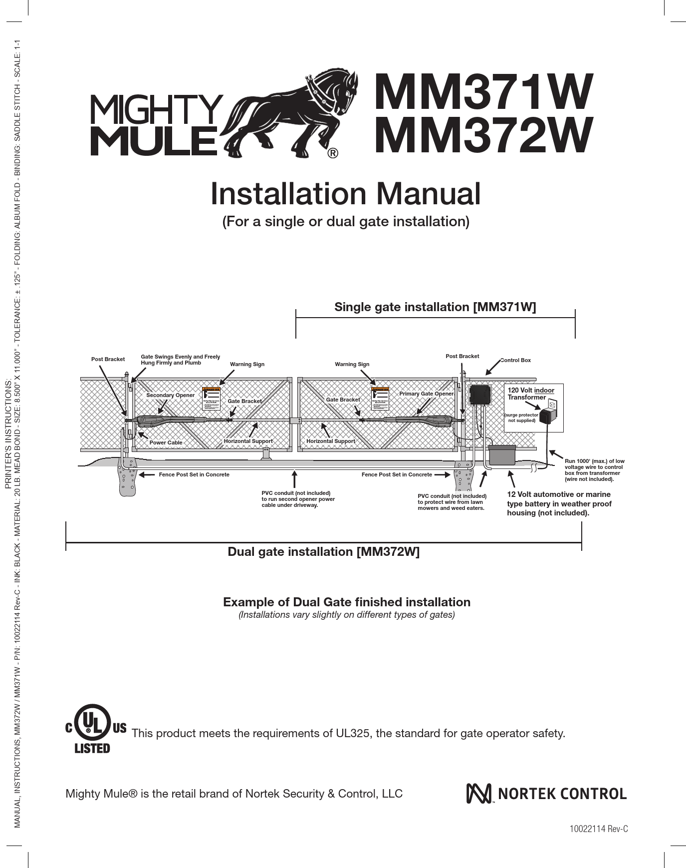
Mighty Mule MM371W / MM372W Installation Manual
(For a single or dual gate installation)
Introduction
Thank you for purchasing a Mighty Mule Gate Operator, Nortek Security & Control's "do-it-yourself" automatic gate operator! When correctly installed and properly used, your Mighty Mule Gate Operator will provide many years of reliable service. Please read the following information to ensure you have the correct system for your particular needs. This manual will enable you to properly install your Mighty Mule Gate Operator.
The Mighty Mule Gate Operator is designed for installation on single or dual gates. The gate(s) must not exceed 16 feet in length or weigh more than 550 pounds (refer to Technical Specifications on page 10). The Mighty Mule Gate Operator can be used on vinyl, aluminum, chain link, farm tube, and wrought iron gates.
Note: Not rated for use on solid surface gates due to the potential to damage the operator and/or injure someone.
The Mighty Mule Gate Operator accommodates extra transmitters, digital keypads, solar panels, push buttons, automatic gate locks, and other access control products. These optional accessories are available at most stores. Your store should be able to special order any accessory not in stock.
If your store cannot special order accessories, please call the Mighty Mule Sales Department at 800-421-1587.
The Mighty Mule Gate Operator features Dual Sense Technology™. This feature makes the gate stop and reverse direction when it comes in contact with an obstruction.
The Mighty Mule Gate Operator also has an adjustable auto-close feature. After the gate reaches the fully open position, it can be set to remain open up to 120 seconds before automatically closing. Pressing the transmitter button at any time after the gate opens fully will cause it to close immediately. The factory setting is OFF, meaning the gate will stay open until you press the transmitter (or keypad, etc.) again.
Visit www.mightymule.com for a retailer near you.
Before you begin to install your automatic gate operator: Read these instructions carefully to become familiar with all parts and installation steps. The video is only designed as an overview of the installation procedure. You must read the installation manual for detailed instructions on gate operator safety and proper use of the gate operator.
Note: Not for the containment of animals.
Important Safety Information
Because automatic gate operators produce high levels of force, consumers need to know the potential hazards associated with improperly designed, installed, and maintained automated gate operator systems. The gate operator is just one component of the total gate operating system; each component must work in unison to provide convenience, security, and safety.
This manual contains safety precautions and warnings for the installer and end user. While not exhaustive, it provides an overview of safe design, installation, and use. Carefully read and follow all safety precautions, warnings, and installation instructions.
Warning Symbol: Warnings in this manual are identified with this symbol [⚠]. This symbol identifies conditions that can result in damage to the operator or its components, serious injury, or death.
The installer and end user are responsible for ensuring the total system is safe for its intended use.
Manually Opening and Closing Gate
CAUTION: The gate will move freely and uncontrolled when the gate operator is removed from the gate. ONLY disconnect the operator when the control box power switch is OFF and the gate is NOT moving.
Disconnecting the Operator
- Turn control box power switch OFF.
- Remove the hairpin clip and clevis pin.
- Remove the operator's front mount from the gate bracket.
The gate can be opened and closed manually when the operator is disconnected.
Note: Substitute a Pin Lock for the clevis pin on the front mount of the gate operator to prevent theft of the operator from the gate (see accessory pages).
Before Installation
- Verify this operator is proper for the type and size of gate, frequency of use, and class of the gate system.
- Ensure the gate has been properly installed and swings freely in both directions. Repair or replace all worn or damaged gate hardware prior to installation. A freely moving gate requires less force and enhances the performance of entrapment protection devices.
- Review the operation of the system to become familiar with its safety features and understand how to disconnect the operator for manual gate operation.
- The gate and operator installation must comply with any applicable local codes.
- This gate operator is intended for vehicular gates only. A separate entrance or gate must be installed for pedestrian use.
- Always keep people and objects away from the gate and its area of travel. No one should cross the path of a moving gate.
- Identify all entrapment zones. An entrapment zone is an area where a person or object could be caught, increasing the risk of injury. Entrapment zones should be eliminated, guarded, or protected.
- When designing a system entered from a highway or main thoroughfare, ensure the gate system is placed far enough from the road to prevent traffic congestion.
Typical Entrapment Zones
Zone 1: Leading edge of the gate and the fence post.
Zone 2: Between the gate and the gate post.
Zone 3: The path of the gate.
Zone 4: The space between the gate in the open position and any adjacent object (wall, fence, tree, etc.).
Zone 5: Pinch points between the operator and gate.
Diagram Description: A diagram illustrates entrapment zones for MM371W (single gate) and MM372W (dual gate) pull-to-open applications, showing Zones 1 through 5 relative to the gate's path and position.
During Installation
- Install the gate operator on the inside of the property and fence line. DO NOT install an operator on the outside where the public has access.
- Be careful with moving parts and avoid close proximity to areas where fingers or hands could be pinched.
- Devices such as contact sensors (sensing edges) and non-contact sensors (photo beams) provide additional protection against vehicular damage.
- If push buttons or key switches are installed, they should be within sight of the gate, located at least 10 feet from any moving part of the gate. Never install any control device where a user might reach through the gate to activate the operator.
- Secure outdoor or easily accessed gate operator controls to prohibit unauthorized use.
Diagram Description: Diagrams show safe distances for control devices (at least 10 feet from moving parts) and indicate areas where control devices should NEVER be installed.
After Installation
- Attach the warning signs to each side of the gate to alert the public. It is your responsibility to post warning signs on both sides. Replace damaged, illegible, or missing signs immediately. Contact Nortek Security & Control for free replacements.
- The gate is automatic and could move at any time, posing a serious risk of entrapment. No one should be in contact with the gate when it is moving or stationary.
- Do not attempt to drive into the gate area while the gate is moving; wait until it comes to a complete stop.
- Do not attempt to "beat the gate" while it is closing; this is extremely dangerous.
- Do not allow children or pets near your gate. Never let children operate or play with gate controls. Keep remote controls away from children and unauthorized users.
- Keep gate systems maintained. Always turn power to the operator OFF before performing any maintenance.
- To operate this equipment safely, know how to disconnect the operator for manual gate operation. If unsure, contact the Mighty Mule Service Department.
- Disconnect the operator ONLY when the power is TURNED OFF and the gate is NOT moving.
- Make arrangements with local fire and law enforcement for emergency access.
- Distribute and discuss copies of the IMPORTANT SAFETY INFORMATION section of this manual with all persons authorized to use your gate.
- Save these safety instructions. Ensure everyone using or around the gate and operator is aware of the dangers. If you sell the property or the operator, provide a copy of these safety instructions to the new owner.
Entrapment and Obstruction Protection: Mighty Mule gate operators utilize Dual Sense Technology™ for entrapment protection. Additional obstruction detection devices like sensing edges and photo beams can be connected. Wiring to sensors must be protected from mechanical damage. Wireless sensors should be located where their signals are not obstructed.
Entrapment Alarm: The operator stops and reverses upon obstruction. An audio entrapment alarm activates if the unit obstructs twice while opening or closing. The alarm sounds for 5 minutes or until a hard-wired signal is received (e.g., push button, keypad). Turning the control box power switch OFF and ON also deactivates the alarm. Wireless controls do not deactivate the alarm.
Diagram Description: Diagrams show example MM371W and MM372W installations, illustrating the placement of warning signs, photo beams, and sensing edges.
Installing Warning Signs and Pedestrian Gates
Warning signs are required and must be installed on each side of the gate to alert the public. A minimum of two signs are needed, visible from each side. Signs must be permanently secured and replaced if damaged or missing.
The operator is intended for vehicular gates only. Pedestrians must use a separate access opening, designed to promote pedestrian usage and located to avoid contact with the vehicular gate during its entire path of travel. A minimum of seven feet separation is recommended.
The Bulldog Pedestrian Gate Lock is recommended for controlled access.
Diagram Description: Diagrams show MM371W and MM372W installations with warning signs and a recommended pedestrian gate placement, indicating a 7-foot minimum separation.
Warning Label (Bilingual):
WARNING / AVERTISSEMENT
Moving gate can cause injury or death!
1. KEEP CLEAR! Gate may move at any time.
2. Read all SAFETY INSTRUCTIONS in the user's manual.
3. Do not allow children to operate gate or play in gate area.
4. This gate is for vehicles only. Pedestrians must use separate entrance.
La barrière en mouvement peut provoquer des blessures graves ou la mort!
1. TENEZ-VOUS LOIN! La barrière peut se déplacer à tout moment.
2. Lisez toutes les instructions de sécurité dans le manuel de l'utilisateur.
3. Ne laissez pas les enfants utiliser la barrière ou jouer à proximité de la barrière.
4. Cette barrière est uniquement réservée aux véhicules. Les piétons doivent utiliser une autre entrée.
Technical Specifications
MIGHTY MULE 371W/372W GATE OPENER
DRIVE
- Low friction screw drive (linear actuator) rated for -20 °C to +71 °C (-5 °F to +160 °F).
- Powered by a 12 V motor with integral gear reducer (motor speed reduced to 348 rpm at 12 V).
- Maximum opening arc of 110°. Approximate opening time (90°): 18 seconds, depending on gate weight.
POWER
- System powered by a 12 Vdc automotive, lawn tractor, or marine battery (required, not included).
- Battery charger is on the controller board, maintained by an included 120Vac to 19VDC output transformer or optional Solar Panels (minimum 10 Watts, 600 mA/20 watt max.). A diode on the control board prevents battery discharge.
- IMPORTANT: Never use both transformer and solar panel simultaneously; this will damage the battery and control board.
- Three (3) Mini blade-style fuses rated for 25A.
- Note: The transformer should not be directly connected to any battery. Do not replace fuses with higher ampere rated fuses, as this will void your warranty and may damage the control board.
CONTROL
- Microprocessor-based control board set for single or dual leaf, pull-to-open or push-to-open installations.
- Control board features temperature-compensated circuits.
- Learn-based digital transmitter technology provides millions of codes for enhanced security (receiver tuned to 318 MHz).
- Opener length with push-pull tube fully retracted: 37 1/4" (mounting point to mounting point). Maximum stroke: 19".
- Adjustable auto-close timer (OFF to 3-120 seconds) and Dual Sense Technology™ stall force.
- Power terminal block accommodates a transformer or solar panels.
- Accessory terminal block is fully compatible with all Mighty Mule access controls.
- Control board allows connection of edge sensors and photoelectric sensors.
- Audio entrapment alarm sounds if the unit encounters an obstruction twice while opening or closing.
OPERATIONAL CAPACITY
| Maximum Weight (lbs.) | Maximum Length (ft.) |
|---|---|
| 550 | 8 |
| 500 | 10 |
| 450 | 12 |
| 400 | 14 |
| 350 | 16 |
Note: Ball bearing hinges should be used on all gates weighing over 250 lb. The Gate Capacity Chart shows the recommended maximum gate length to weight. The minimum recommended gate length is 5 ft.
Before You Begin
Powering Options
1. Determine Charging Option for Battery: Transformer OR Solar
NEVER USE TRANSFORMER AND SOLAR PANEL(S) AT THE SAME TIME. It will damage the control board.
The Mighty Mule 371 and 372 are designed for use with a 12 Volt automotive, marine, or lawn tractor battery. The battery must be placed inside a weatherproof case and located within 6 feet of the control box. The 8-foot battery harness connects the battery to the control board.
The battery charge is maintained by the 19 Volt transformer included OR optional solar panel(s). The transformer OR solar panel is connected to the control board using low voltage, 16 gauge, dual conductor, multi-stranded, direct burial wire [RB509] (page 52).
The transformer is intended for indoor use. If it can only be plugged into an outside electrical outlet, a weatherproof cover or housing must be used.
If your gate is more than 1000 feet from an AC power source, you will need a solar panel charging kit (minimum 10 watts). Refer to the Solar Panels and Gate Activity Chart below.
Note: If the gate operator controller is OFF, the system will NOT charge the battery.
Solar Panel and Gate Activity Chart
The table and map illustrate the maximum number of gate cycles to expect per day in a particular area when using 10 to 30 watts of solar charging power before the battery depletes to a state where the unit will not function. These figures are for winter (minimum sunlight). Accessories connected to your system will draw additional power from the battery.
A deep cycle marine battery is recommended for solar and/or high traffic applications.
Note: Up to 250 feet of dual conductor, 16 gauge, multi-stranded wire may be used to allow installation of solar panels in direct sunlight.
| Single Gate Winter Ratings | Zone 1 | Zone 2 | Zone 3 |
|---|---|---|---|
| 12V single gate (10 watts) solar charger | 8 | 16 | 26 |
| 12V single gate (20 watts) solar charger | 14 | 28 | 38 |
| 12V single gate (30 watts) solar charger | 20 | 44 | 54 |
* Power increments are for reference only.
Diagram Description: A map of the United States is divided into three zones (Zone 1, Zone 2, Zone 3) indicating solar charging suitability.
Check Existing Gate Size and Material
- Gate size: Up to 16 feet and up to 550 lbs. (See Operational Capacity chart on page 10).
- Type of gate material: Vinyl, aluminum, chain link, farm tube, wrought iron, wood.
- Note: Not rated for use on solid surface gates.
IMPORTANT: Check for Proper Gate Installation
- The gate must be plumb, level, and swing freely on its hinges.
- The gate must move throughout its arc without binding or dragging on the ground.
- Wheels must NOT be attached to the gate.
- Gates over 250 lb. should have ball bearing hinges with grease fittings.
- Posts must be secured in the ground with concrete to minimize twist/flex when the operator is activated.
- Ensure there is a stable area for mounting the gate bracket (this may require a horizontal or vertical cross member).
- Position the operator near the center-line of a gate to keep it from twisting and flexing, and to avoid back-splash from rain.
Diagram Description: A diagram shows a gate post and gate, with labels indicating key checks: A - Level, B - Plumb, C - Free Swinging, D - Secured Posts in Concrete, E - Center line Mounting, F - Good Working Hinges (ball bearing hinges recommended for gates over 250 lbs).
Gate Grounding
For reference only.
Use an 8-foot, 5/8-inch ground rod, positioned two feet or less from the post and 2 inches or less above the ground. Available at local home or hardware stores.
Note: No grounding system absolutely protects against lightning strikes. A correctly installed grounding system will help minimize damage to your gate operator.
Diagram Description: A diagram illustrates gate grounding setup, showing a metal gate post, a copper clad ground rod, a copper single conductor lug, and a copper ground rod clamp, with measurements for placement.
Items Included for Primary Gate Opener Installation (MM371W)
Diagram Description: An exploded view diagram lists and labels all components included for the MM371W primary gate opener installation, including Operator Arm, Control Box, Antenna & Battery Harness, Transformer, Gate Bracket, Post Pivot Bracket, Post Brackets (2), Literature kit with gate warning signs, MMT103 Transmitter, and various hardware items (bolts, nuts, washers, clips, screws, cable ties).
Items Included for Secondary Opener Installation (MM372W)
Diagram Description: An exploded view diagram lists and labels all components included for the MM372W secondary gate opener installation, identical to the primary installation except for the absence of the Transformer and MMT103 Transmitter.
Tools and Items Not Included
Tools Needed
Diagram Description: A collection of icons represents various tools required for installation: Drill with bits (7/16", 1/2", 7/32"), Pen, Center Punch, Pliers, Hack Saw, 1/2" wrench, 9/16" wrench, Adjustable Wrench, Hammer, Level, Clamps, Philips Head Screwdriver, Flat Head Screwdriver, Wire Stripper, Small Tape Measure.
Items Not Included
- 12 Volt Auto or Marine Battery
- 16 gauge standard low voltage direct burial wire (length depends on distance between transformer and control box; see Transformer/Solar Wiring on page 34).
- PVC conduit.
- If you have thin-walled tube or panel gates, see Reinforcing Gates for the Gate Brackets section.
- Depending on gate type, a horizontal cross member or mounting plate may be needed for the operator and gate bracket. See Reinforcing Gates for the Gate Brackets examples.
- Surge protection for transformer.
- Some installations may require U-bolts.
- Additional washers or a metal plate may be needed for wooden posts.
- Weatherproof cover for outdoor outlet and transformer.
- If the post is larger than 6", bolts longer than 8" are needed.
Check Direction of Gate Swing
Pull-to-Open Option: Instructions begin on page 2.
Push-to-Open Option: Instructions begin on page 8. (Requires Push-to-Open Bracket #FM148 - NOT INCLUDED).
Diagram Description: Two diagrams illustrate gate swing direction relative to the property line, one for Pull-to-Open and one for Push-to-Open.
Mechanical Installation
Assessing the Gate for Installation
Your gate operator can be mounted to various gate types. This section shows common setups and recommended reinforcement methods.
Reinforcing Gates for the Gate Brackets
Use a muffler clamp, wood, or metal to reinforce thin-walled tube or panel gates. These methods prevent damage to the opener and gate. Additional hardware may be needed.
Diagram Description: Diagrams show methods for reinforcing gates for bracket mounting: using a muffler clamp on a thin-walled tube gate, and using wood or metal reinforcement on a panel gate.
Pull-to-Open Operator Mounting (Most Common)
Step 1: Assemble the gate post bracket sub-assembly.
Step 2: Attach the gate post bracket sub-assembly and gate bracket to the operator.
Step 3: With the gate in the OPEN position, use clamps to secure the operator to the gate post and center cross member of the gate. Ensure the operator is level. Check for at least 2 inches of clearance between the operator arm and gate.
Step 4: Disconnect the operator arm from the gate bracket. Swing the gate and operator to the closed position. Check for recommended clearances and binding. Ensure the rear mount of the operator does not press against the post pivot bracket assembly in the closed position. Ensure the arm stroke does not exceed 17 inches. Make adjustments to mounting brackets as needed.
Diagram Description: Step-by-step diagrams illustrate the process of mounting the operator for pull-to-open applications, showing bracket assembly, attachment to the gate and post, and clearance checks in both open and closed positions. A top view diagram highlights pinch-point clearance and maximum stroke.
Warning: Ensure the rear mount does not make contact with the post-bracket assembly during any point of the gate travel.
Step 5: Open the gate and reattach the operator to the gate bracket. Ensure the operator arm is level and brackets are securely clamped. Secure the post pivot bracket by installing hardware and tightening bolts.
Step 6: Using a permanent marker, mark the center of mounting locations for the gate post bracket sub-assembly. Remove the operator arm from the gate post and gate brackets. Mark the center of mounting locations for the gate bracket.
Step 7: Remove the gate post and gate brackets. Use a hammer and center punch to mark the center of the mounting locations.
Step 8: Using a drill and 7/16" bit, drill the necessary holes to mount the gate post and gate brackets. Note: Some installations may require additional reinforcement.
Step 9: Secure the gate post bracket sub-assembly with the supplied hardware.
Step 10: Secure the gate bracket with the supplied hardware.
Step 11: Once the gate post and gate brackets are installed, reattach the operator arm. Ensure the operator arm is level, adjusting the post bracket location if necessary. Ensure all hardware is tight. Remove excess bolt length with a hacksaw.
Diagram Description: Further step-by-step diagrams illustrate completing the pull-to-open mounting process, including reattaching the arm, marking, drilling, and securing brackets.
Installing the Closed Position Stop Plate / Pull-to-Open
Step 1: Remove the operator from the gate post and brackets. With the gate fully open, install the closed position stop plate (hardware not included). Do not fully tighten until the next step.
Step 2: Swing the gate to the closed position and adjust the stop plate against the fence post. Tighten mounting hardware. Return the gate to the open position and reinstall the operator arm.
Diagram Description: Diagrams show the installation of the closed position stop plate for pull-to-open systems.
Note for MM372W: The closed position stop plate should be installed on the leading edge of the PRIMARY gate leaf and adjusted to close against the leading edge of the SECONDARY gate leaf.
Installing the Ground Stop Plate (for MM372 Installations)
An optional low profile ground stop, used with the closed position stop plate, provides a secure closing point for the SECOND gate. For Pull-to-Open systems, install Ground Stop Plates on the inside of the gates. For Push-to-Open systems, install on the outside.
Step 1: Detach gate opener arms and move gates to the closed position.
Step 2: The low profile ground stop (metal or concrete) should be firmly secured in the ground beneath the SECOND gate, near the leading edge.
Step 3: Attach the vertical closed position stop plate to the SECOND gate frame where it contacts the ground stop. Slide the plate until it touches the ground stop, then tighten hardware.
Step 4: Return gates to open positions and reattach gate openers.
Diagram Description: Diagrams illustrate the installation of the ground stop plate and closed position stop plate for dual gates.
Push-to-Open Operator Mounting
Step 1: Assemble the gate post bracket sub-assembly with the Push-to-Open pivot bracket (FM148 - sold separately).
Step 2: Attach the gate post bracket sub-assembly and gate bracket to the operator. The operator must be fully retracted with the gate in the desired closed position.
Step 3: With the gate in the CLOSED position, use clamps to secure the operator to the gate post and center cross member. Ensure the operator is level. Check for at least 2 inches of clearance between the operator arm and gate.
Step 4: Disconnect the operator arm from the gate bracket. Swing the gate and operator to the OPEN position. Check clearances and binding. Ensure arm stroke does not exceed 20 inches. Adjust mounting brackets as needed.
Diagram Description: Step-by-step diagrams illustrate the push-to-open mounting process, similar to pull-to-open but with the gate in the closed position initially. A clearance diagram shows maximum stroke and minimum pinch-point clearance.
Warning: The operator must be installed while fully retracted, with the gate in the closed position.
Step 5: Close the gate and reattach the operator to the gate bracket. Ensure the arm is level and brackets are clamped. Secure the push-to-open bracket.
Step 6: Mark the center of mounting locations for the gate post bracket sub-assembly. Remove the operator arm. Mark the center of mounting locations for the gate bracket.
Step 7: Remove gate post and gate brackets. Use hammer and center punch to mark mounting locations.
Step 8: Drill holes to mount the gate post and gate brackets. Note: Reinforcement may be needed.
Step 9: Secure the gate post bracket sub-assembly.
Step 10: Secure the gate bracket.
Step 11: Reattach the operator arm. Ensure it is level, adjusting the post bracket if necessary. Tighten all hardware. Remove excess bolt length.
Diagram Description: Further step-by-step diagrams illustrate completing the push-to-open mounting process.
Installing the Closed Position Stop Plate / Push-to-Open
Step 1: Remove the operator from the gate post and brackets. Swing the gate to the open position. Install the closed position stop plate on the gate opposite the operator (hardware not included). Do not fully tighten.
Step 2: Swing the gate to the closed position and adjust the stop plate against the fence post. Tighten hardware. With the gate in the closed position, reinstall the operator arm.
Note for MM372W: The closed position stop plate should be installed on the leading edge of the PRIMARY gate leaf and adjusted to close against the leading edge of the SECONDARY gate leaf.
Control Box Installation
Step 1: Identify a suitable mounting location for the control box at least 3 ft. from the ground and no more than 4 ft. from the primary operator. Recommended location: at least 5 ft. from the ground to improve radio performance.
Step 2: Loosen the four cover screws, open the control box cover. Locate mounting locations marked 'P' inside and use them to mount the box with supplied wood screws. If mounting to a metal post, use a wood panel.
Step 3: Install the Antenna by screwing it onto the SMA connector. Orient it straight upward and tighten securely.
Diagram Description: Diagrams show control box mounting locations and antenna installation.
Connecting the Operator(s) and Battery
Step 1: Remove the sealing nut from a cable gland on the bottom of the control box. For MM372W, repeat for the secondary operator. Feed the operator wiring harness through the sealing nut.
Step 2: Insert the wire harness through the cable gland into the control box (at least 3" to allow connection to terminals). Secure the cable by tightening the sealing nut. For MM372W, repeat for the secondary operator.
Step 3: Locate the PRIMARY operator wiring terminals and insert wires into corresponding color terminals. For MM372W, repeat for the SECONDARY operator. Tighten screw terminals.
Step 4: Connect the battery power wires: Red to Red (BAT+) and Black to Black (BAT-).
Diagram Description: Diagrams illustrate connecting the operator wiring harnesses to the control box and connecting the battery power wires.
Transformer or Solar Panel Wiring Installation
WARNING: Before digging, contact local authorities to locate underground utilities.
Step 1: Locate a power outlet and identify the wire path to the control box. If installing a solar panel, refer to its manual. If the outlet is outside, use a weatherproof cover.
Step 2: Dig a trench to lay the low voltage transformer wire [RB509]. Use PVC conduit from the ground up to the control box. Conduit in trench is recommended.
CAUTION: Call your power company before you dig.
Step 3: Feed the transformer or solar panel wires into the control box using an access location. Connect the RED wire to PWR+ and the BLACK wire to PWR- on TERM 6.
Step 3B (MM372 Only): For dual arm installation, drill through an Alternate Access slot to install transformer or solar power wires. Run PVC conduit under the driveway to protect the second opener power cable and low voltage wire. Repeat steps 1-3 for connecting the secondary operator cable to the control board.
Step 4: From the other end of the low voltage wire, strip 1/2" from both RED and BLACK wires. On the transformer, connect RED to the '+' terminal and BLACK to the '-' terminal. Plug the transformer into the electrical outlet.
Note: Use of a surge protector is strongly recommended.
Diagram Description: Diagrams show transformer wiring, trenching for low voltage wire, and control box connections for transformer/solar power.
Electrical Installation and Setup
Dip Switches Settings
- Push/Pull-to-Open: ON = Push, OFF = Pull. (Unit must be reset or power cycled for changes to take effect).
- Stagger (for MM372W): OFF = Gates open simultaneously, close staggered. ON = Gates stagger opening and closing (for compatibility with gate locks).
- Warning: Toggles a movement alarm ON or OFF.
Diagram Description: A close-up view of the control board shows the DIP switches labeled PUSH/PULL, STAGGER, and WARNING, along with other components.
Powering the System
Locate the ON/OFF switch on the bottom left of the control box and toggle it to ON. The system will take approximately 20 seconds to power up, indicated by an audible tone and LED D17 flashing.
Transmitter Programming
How to Learn a Transmitter:
- On the control board, press and hold the (return/enter) button until LED2 turns on and the buzzer sounds. Release the button.
- Press and hold the desired transmitter button. Once learned, LED2 will flash and the buzzer will sound.
How to Erase a Transmitter or Keypad (MMK200) code:
Repeat steps 1-2 above to erase the learned transmitter or keypad code.
How to Erase ALL Learned Transmitters or Keypad codes:
- Enter the 'Learn Transmitter' mode (step 1 above).
- Press and hold the (down arrow) button until LED1, 2 & 3 flash and the buzzer sounds (approx. 10 seconds).
Note: The control board can store a total of 50 transmitter and/or keypad codes. The system is compatible with Mighty Mule DIP switch transmitters and keypads.
Warning: Changes or modifications not expressly approved by Nortek Security & Control, LLC could void the user's authority to operate this equipment. There are no user-serviceable parts.
Closed Limit Programming - Pull to Open
371 Closed Limit Programming For Pull-to-Open Applications
Button Configuration: S2 = (Extend/Close), S3 = , S4 = (Retract/Open)
Step 1: Enter the primary arm limit programming mode. Press and hold the [extend/close] and [retract/open] buttons simultaneously until LED 1 turns on and the buzzer sounds. Release buttons.
Step 2: Program the primary arm closed limit. Press and hold the [extend/close] button. The arm will extend, closing the gate. Continue holding until the desired closed position is reached, then release. Use the [retract/open] button to reverse if you overshoot. Press and hold [extend/close] then release to set the limit.
Note: Three short beeps indicate programming mode timeout. You can re-enter programming mode without starting over. If the closed position is correct but timed out, press and hold [extend/close] then release, then immediately press and hold [retract/open] then release.
Diagram Description: A view of the control board shows DIP switches and programming buttons used for limit setting.
372 Closed Limit Programming For Pull-to-Open Applications
Step 1: Enter the secondary arm limit programming mode. Press and hold the [extend/close] and [retract/open] buttons until LED 3 turns on and the buzzer sounds. Release.
Step 2: Program the secondary arm closed limit. Press and hold [extend/close]. The arm will extend, closing the gate. Continue holding until the desired closed position is reached, then release. Use [retract/open] to reverse if you overshoot. Press and hold [extend/close] then release to set the limit.
Note: Three short beeps indicate timeout. Re-enter programming mode. If closed position is correct but timed out, press and hold [extend/close] then release, then immediately press and hold [retract/open] then release.
Step 3: Enter the primary arm limit programming mode. Press and hold the [extend/close] and [retract/open] buttons until LED 1 turns on and the buzzer sounds. Release.
Step 4: Program the primary arm closed limit. Press and hold [extend/close]. The arm will extend, closing the gate. Continue holding until the desired closed position is reached, then release. Use [retract/open] to reverse if you overshoot. Press and hold [extend/close] then release to set the limit.
Note: Three short beeps indicate timeout. Re-enter programming mode. If closed position is correct but timed out, press and hold [extend/close] then release, then immediately press and hold [retract/open] then release.
Closed Limit Programming - Push to Open
371 Open Limit Programming For Push-to-Open Applications
Button Configuration: S2 = (Extend/Close), S3 = , S4 = (Retract/Open)
Step 1: Enter the primary arm limit programming mode. Press and hold the [extend/close] and [retract/open] buttons until LED 1 turns on and the buzzer sounds. Release.
Step 2: Program the primary arm closed limit. Press and hold the [extend/close] button. The arm will extend, opening the gate. Continue holding until the desired open position is reached, then release. Use [retract/open] to reverse if you overshoot. Press and hold [extend/close] then release to set the limit.
Note: Three short beeps indicate timeout. Re-enter programming mode. If open position is correct but timed out, press and hold [extend/close] then release, then immediately press and hold [retract/open] then release.
372 Open Limit Programming For Push-to-Open Applications
Step 1: Enter the primary arm limit programming mode. Press and hold the [extend/close] and [retract/open] buttons until LED 1 turns on and the buzzer sounds. Release.
Step 2: Program the primary arm closed limit. Press and hold [extend/close]. The arm will extend, opening the gate. Continue holding until the desired open position is reached, then release. Use [retract/open] to reverse if you overshoot. Press and hold [extend/close] then release to set the limit.
Note: Three short beeps indicate timeout. Re-enter programming mode. If open position is correct but timed out, press and hold [extend/close] then release, then immediately press and hold [retract/open] then release.
Step 3: Enter the secondary arm limit programming mode. Press and hold the [extend/close] and [retract/open] buttons until LED 3 turns on and the buzzer sounds. Release.
Step 4: Program the secondary arm open limit. Press and hold [extend/close]. The arm will extend, opening the gate. Continue holding until the desired open position is reached, then release. Use [retract/open] to retract. Press and hold [extend/close] then release to set the limit.
Note: Three short beeps indicate timeout. Re-enter programming mode. If open position is correct but timed out, press and hold [extend/close] then release, then immediately press and hold [retract/open] then release.
Dual Sense Stall Force Setting
Do not use the Dual Sense Stall Force adjustment to compensate for a gate that is sticking or binding, as excessive force may damage the system. This adjustment controls the force applied before the opener stops and reverses.
Adjusting the Stall Force:
- Press and hold the [extend/close] and [retract/open] buttons until the buzzer sounds (approx. 2 seconds). Release.
- Use the [extend/close] and [retract/open] buttons to adjust the Stall Force setting. LED1, 2, & 3 indicate the setting: LED3 ON = LOW, LED3 & 2 ON = MEDIUM, LED1, 2 & 3 ON = HIGH.
- Press the [return/enter] button until the buzzer sounds, then release to set the Stall Force.
Diagram Description: A view of the control board shows DIP switches and programming buttons used for stall force adjustment.
Auto Close Setting
Step 1: The auto close timer is set to OFF from the factory. To set a timer, use a small flat head screwdriver to turn the auto close potentiometer clockwise. The timer can be set from approximately 3 seconds to a maximum of 120 seconds.
Step 2: If you have additional accessories to install, see the next page. Otherwise, your installation is complete. Review the installation checklist.
Diagram Description: A diagram shows the auto close potentiometer on the control board.
Optional Smart Control Setup
This product can be controlled via a smart device (smartphone) with the addition of the MMS100 smart kit. Refer to the MMS100 kit instructions or visit www.mightymule.com for more information.
Connecting Additional Devices
Mighty Mule recommends using additional obstruction detection devices but does not endorse specific brands. Use only products listed as compliant with applicable UL safety standards and national/regional codes. Contact sensors, non-contact sensors, shadow loops, etc., are not included. Refer to the sensor manufacturer's instructions. Mighty Mule ONLY accepts accessory devices with normally open dry contact outputs.
WARNING: Make sure the operator power switch is OFF before connecting ANY device wiring to the controller terminals. Unplugging the transformer does not turn power off.
Wiring Accessories through Control Board Wiring Knockout
- Open the control box cover.
- Carefully remove wiring knockout plugs to insert accessory wires.
- Insert accessory wires through the knockout and route to the accessory input terminals on the control board.
- Close the control box cover.
Diagram Description: A diagram shows the control box with wiring knockout plugs and accessory wire routing to the control board terminals.
Control Board Connections
Notes:
- All ACCESSORY INPUTS (ITEMS 2-6) are dry contact, normally open inputs. DO NOT apply external voltage.
- All ACCESSORY INPUTS (ITEMS 2-6) are connected with respect to the COMMON terminals (ITEM 1).
Accessory Inputs:
- COM: Common/Negative terminal for accessory devices and negative wire from solar panel(s).
- CYCL: (Doorbell button or hard-wired keypad) Cycles operation: OPEN → STOP → CLOSE → STOP → OPEN...
- SAFE: (Photo beam, loop detector, etc.) If gate is closing, stops and reverses to open. If gate is opening, no effect. If gate is open, prevents closing. At open limit, restarts auto-close timer.
- EXIT: (Exit loop or wand) Opens gate if not already open. At open limit, restarts auto-close timer.
- SHDW: (Loop detector) Monitored only when gate is fully open. Prevents closing.
- EDGE: (Contact edge sensor) If gate is moving, reverses direction for 2 seconds. If idle, prevents running.
Outputs:
- AUX V+ & AUX V-: Constant auxiliary accessory power from battery (2 amps MAX). Used with AUX relay (ITEM 8). Note: Drains battery; continuous use > 20mA not recommended for solar.
- AUX C NO NC: AUX Relay triggered during gate operation. Switches AUX V-.
- LOCK V+ & LOCK V-: For Automatic Gate Lock (FM143).
- LOCK C NO NC: LOCK Relay momentarily triggered at start of gate operation. Switches LOCK V-.
Note: DO NOT connect positive voltage to AUX or LOCK Relays.
Diagram Description: A detailed diagram shows the control board with numbered terminals for Accessory Inputs and Outputs, and their functions.
Connecting Accessories
Diagram Description: Diagrams illustrate typical wiring connections for various accessories: Garage Door Receiver, Automatic Gate Lock (FM143), Mighty Mule Vehicle Sensor, Mighty Mule Push Button Control, Mighty Mule Keypad, Photo Beams, Edge Sensor, and a Light Bulb (active while cycling). Each diagram shows the accessory and its connection points to the control board, including power and signal wires.
Note: Connections are for typical applications. Refer to accessory manuals for additional options.
Maintenance & Troubleshooting
Maintenance
- Monthly: Test obstruction and entrapment protection systems.
- Monthly: Service operator (power switch OFF). Clean extended operator arm with a soft, dry cloth.
- For gates 250 lb. or more: Routinely grease ball bearing hinges at least 4 times a year (more if near coastal area).
- Monthly: Turn power OFF, disconnect operator, and move gate manually to ensure it moves freely. Lubricate or repair hinges as needed before reattaching operator.
- Monthly: Check gate system for potential entrapments from new landscaping or construction. Eliminate or guard as required.
- Monthly: Check that warning signs are mounted and visible. Replace if missing or damaged.
- Replace batteries every 2-3 years and recycle old batteries properly.
Troubleshooting Guide - Audible Feedback
Use this guide before calling Nortek Security & Control Service Department.
| Audible Feedback | Possible Diagnosis | Check/Solution |
|---|---|---|
| Continuous Alarm | Control Board senses an obstruction or lack of arm movement |
|
| 1 beep every 10 seconds | Low battery |
|
| 2 beeps every 10 seconds | Motor fault |
|
| 1 beep, pause, 1 beep,... | Open circuit Primary arm |
|
| 2 beeps, pause, 2 beeps,... | Open circuit Secondary arm |
|
| 3 beeps, pause, 3 beeps,... | Short circuit Primary arm |
|
| 4 beeps, pause, 4 beeps,... | Short circuit Secondary arm |
|
| 5 beeps, pause, 5 beeps,... | Stuck limit switch Primary Arm or reading open motor circuit |
|
| 6 beeps, pause, 6 beeps,... | Stuck limit switch Secondary arm or reading open motor circuit |
|
| 1 beep, pause, 3 beeps, pause, 1 beep, pause, 3 beeps, pause,... | Reading secondary motor short condition |
|
| The unit clicks with no arm movement | Internal motor problem or low battery |
|
Additional information can be found by contacting Nortek Security & Control.
Troubleshooting Guide - Visual Feedback
| Visual Feedback | Possible Diagnosis | Check/Solution |
|---|---|---|
| The unit does not seem to turn on | Blown fuse(s) Lack of power Power switch |
|
| The unit will not run | 1) Closed/open limit(s) not programmed 2) Transmitter not programmed 3) Battery issues 4) Arm problem |
|
| The unit stops before reaching the proper open or close position. | Limit position not adjusted/set correctly. The unit is receiving a stop command Hardware not positioned correctly |
|
| The unit reverses before completing an open or close. | Gate/unit has sensed an obstruction |
|
| Charge LED rapidly flashing | Unit does not detect the presence of a battery |
|
| Charge LED off | Unit not charging |
|
| Charge LED Flashing | Battery or Batteries disconnected |
|
| LED 2 (red) 1 blink, pause, 1 blink,... | Cycle (CYCL) terminal shorted | Detach all wires connected to the affected terminal. Turn system power OFF and back ON. After the start-up beep, ensure system functions as expected. Troubleshoot each accessory and wiring individually. |
| LED 2 (red) 2 blinks, pause, 2 blinks,... | Safety (SAFE) terminal shorted | Detach all wires connected to the affected terminal. Turn system power OFF and back ON. After the start-up beep, ensure system functions as expected. Troubleshoot each accessory and wiring individually. |
| LED 2 (red) 3 blinks, pause, 3 blinks,... | Exit (EXIT) terminal shorted | Detach all wires connected to the affected terminal. Turn system power OFF and back ON. After the start-up beep, ensure system functions as expected. Troubleshoot each accessory and wiring individually. |
| LED 2 (red) 4 blinks, pause, 4 blinks,... | Shadow (SHDW) terminal shorted | Detach all wires connected to the affected terminal. Turn system power OFF and back ON. After the start-up beep, ensure system functions as expected. Troubleshoot each accessory and wiring individually. |
| LED 2 (red) 5 blinks, pause, 5 blinks,... | Close Edge (CLOSE EDGE) terminal shorted | Detach all wires connected to the affected terminal. Turn system power OFF and back ON. After the start-up beep, ensure system functions as expected. Troubleshoot each accessory and wiring individually. |
| LED 2 (red) 6 blinks, pause, 6 blinks,... | Open Edge (OPEN EDGE) terminal shorted | Detach all wires connected to the affected terminal. Turn system power OFF and back ON. After the start-up beep, ensure system functions as expected. Troubleshoot each accessory and wiring individually. |
| The auto close seems to be working in reverse and/or accessories not operating properly | Dip switch 1 in the wrong position, or was not updated by the system |
|
| F1 fuse (top left) blown | Transformer or solar wired to board incorrectly |
|
| F2 fuse (bottom left fuse) blown | Battery or Batteries connected incorrectly |
|
| Harness fuse blown | Battery or Batteries connected incorrectly |
|
Unit requires power cycle in order to reset the error.
Additional information can be found by contacting Nortek Security & Control.
Repair Service
If your Mighty Mule Gate Opener is not operating properly, please follow these steps:
- First, use the procedures found in the Maintenance & Troubleshooting Guide (page 46).
- For 24/7 troubleshooting and support online, visit the TECH WIZARD site at www.mightymule.com.
- If you cannot solve the problem, call the Tech Service Department at 800-543-1236.
- If repair or replacement is necessary, the Service Department will assign a Return Authorization (RA) number.
- Include a copy of your receipt and securely pack the component(s) authorized for return. Write the RA number in LARGE BOLD PRINT on the outside of the package. Ship freight prepaid to the address provided during the RA process.
Note: Products returned without an RA number in LARGE BOLD PRINT on the package WILL NOT be accepted. Items returned freight collect WILL NOT be accepted. Items returned without proof of purchase will not be repaired under warranty.
Technical Service Department Hours: Monday - Friday, 8:00 A.M. – 7:00 P.M. (Eastern Time).
Web site: www.mightymule.com
Accessories
Accessories are available from your retail store.
Solar Panel (FM123)
A 10-watt solar powered battery charger for Mighty Mule 571W/572W gate operator systems. Suitable for remote installations. Includes tubular steel support, mounting clips, wire connectors, and 10 ft. of low voltage wire. The Mighty Mule control board has labeled terminal connections for easy installation. Some regions may require multiple solar panels (30 watt max).
MMT103 Code Safe Digital Transmitter
A wireless radio control for Mighty Mule garage door openers and gate openers. One remote for multiple devices.
Pin Lock (FM133)
Substitutes for the clevis pin at the front of the operator to help prevent theft while allowing quick release.
Wireless Driveway Vehicle Sensor (FM130)
Automatically activates the gate operator hands-free when a vehicle exits the property. 100 ft. range between transmitter and receiver. Easy installation.
Wireless Connectivity System (MMS100)
Adds smart functionality to your gate operator using the Mighty Mule App.
Wireless Keypad (MMK200)
Controls access to Mighty Mule garage door openers and gate openers. Features an LED backlight for visibility in low light conditions.
Mounting Post (FM100) - In Ground
A black powder-coated pedestal for convenient access to keypads, wireless intercoms, or other access control devices. Easy to install. Surface Mount Flanges (F102) and Extensions (F103) are available.
Mighty Mule Vehicle Sensor (FM138)
A gate opening sensor for residential and agricultural applications. An electromagnetic sensor offering hands-free operation with a 12 ft. detection radius for vehicles in motion.
Automatic Gate Lock Pull-to-Open (FM143)
For added security. Solenoid driven with a steel housing. Used with Mighty Mule DC swing gate systems for maximum stability and security. Comes with a keyed manual release.
Diagram Description: Images display various accessories including Solar Panel, MMT103 Transmitter, Pin Lock, Wireless Driveway Vehicle Sensor, Wireless Connectivity System, Wireless Keypad, Mounting Post, Mighty Mule Vehicle Sensor, and Automatic Gate Lock.
Appendix A: Accessory Installation Instructions
FM130 Installation
For the FM130 to function, the "Transmitter Module" must be programmed to your gate operator's control board.
Before you begin:
- Ensure the gate operator is in the OPEN position.
- Check the PUSH-PULL DIP setting (page 35). If changed, turn unit OFF then ON.
- Ensure AUTOCLOSE is set to OFF.
Step 1: Choose a random dip switch setting on the Transmitter Module.
Step 2: On the gate operator control board, press and hold the [extend/close] (S3) button until LED2 illuminates and the buzzer sounds. Release.
Step 3: Insert batteries into the transmitter module. It will begin transmitting.
Step 4: Once learned, LED2 will flash and the buzzer will sound. Remove AA batteries from the Transmitter Module and proceed with accessory instructions.
Notes:
- To erase this device, repeat steps 2-4.
- Erasing all transmitters on the control board will erase this device.
- AUTOCLOSE may be turned back on after setup.
Diagram Description: Diagrams show the FM130 transmitter module and its programming steps.
FM136 Installation
To learn the keypad to your gate operator as an additional transmitter:
Step 1: Choose a random DIP setting on the keypad unit (refer to FM136 manual).
Step 2: On the control board, press and hold the [extend/close] (S3) button until LED2 illuminates and the buzzer sounds. Release.
Step 3: Enter your MASTER CODE on the FM136 keypad (default is 1-2-3-4). Once learned, LED2 will flash and the buzzer will sound. Proceed with FM136 installation per accessory instructions.
Notes:
- To erase this device, repeat steps 2-3.
- Erasing all transmitters on the control board will erase this device.
Diagram Description: Diagram shows the FM136 keypad and its programming steps.
Gate Operator Installation Checklist
- The gate has been checked to ensure it is level and moves freely in both directions.
- Potential pinch areas have been guarded or have sensing edges/photo beam obstruction detection devices installed.
- Installer has installed required contact or non-contact obstruction sensing devices.
- If pedestrian traffic is expected, a separate pedestrian gate has been installed at least seven feet from the gate system. All pedestrian traffic must use the pedestrian gate.
- Warning signs have been installed on each side of the gate in highly visible locations and must remain at all times.
- There are no controls installed on the gate operator or within 10 feet of the gate.
- The Dual Sense Technology™ feature has been properly adjusted to the minimum operational setting for the application.
- Reviewed and understand all operational functions, obstruction sensing devices, warning beeper, and reset procedures.
- Reviewed and understand the proper use of the operator's manual disconnect feature. The manual disconnect must never be used while the gate is in motion. The power switch must be turned OFF before using the manual disconnect and disengaging the operator.
- Reviewed all safety instructions and keep them and owner's information sheets for reference.
- Review and understand the maintenance schedule for both the gate and the gate operator.
Contact Information:
Mighty Mule Sales: (800) 543-4283
Mighty Mule Technical Support: (800) 543-1236
Web site: www.mightymule.com
Copyright © 2021 Nortek Security & Control, LLC. All rights reserved.
