msi PRO Z690-A WIFI/ PRO Z690-A Motherboard User Manual
File info: application/pdf · 249 pages · 8.66MB
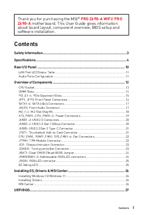
MSI Pro Z690-A WIFI Manual
Extracted Text
Thank you for purchasing the MSI� PRO Z690-A WIFI/ PRO Z690-A motherboard. This User Guide gives information about board layout, component overview, BIOS setup and software installation.
Contents
Safety Information........................................................................................... 3
Specifications................................................................................................... 4
Rear I/O Panel ............................................................................................... 10 LAN Port LED Status Table ......................................................................................11 Audio Ports Configuration ........................................................................................11
Overview of Components .............................................................................. 12 CPU Socket ...............................................................................................................13 DIMM Slots................................................................................................................14 PCI_E1~4: PCIe Expansion Slots..............................................................................15 JFP1, JFP2: Front Panel Connectors.......................................................................16 SATA1~6: SATA 6Gb/s Connectors...........................................................................17 JAUD1: Front Audio Connector ................................................................................17 M2_1~4: M.2 Slot (Key M) .........................................................................................18 ATX_PWR1, CPU_PWR1~2: Power Connectors.......................................................19 JUSB1~2: USB 2.0 Connectors.................................................................................20 JUSB3~4: USB 3.2 Gen 1 5Gbps Connector .............................................................20 JUSB5: USB 3.2 Gen 2 Type-C Connector................................................................21 JTBT1: Thunderbolt Add-on Card Connector ..........................................................21 CPU_FAN1, PUMP_FAN1, SYS_FAN1~6: Fan Connectors......................................22 JTPM1: TPM Module Connector...............................................................................22 JCI1: Chassis Intrusion Connector...........................................................................23 JDASH1: Tuning controller Connector.....................................................................23 JBAT1: Clear CMOS (Reset BIOS) Jumper...............................................................24 JRAINBOW1~2: Addressable RGB LED connectors ................................................24 JRGB1: RGB LED connector.....................................................................................25 EZ Debug LED...........................................................................................................25
Installing OS, Drivers & MSI Center.............................................................. 26 Installing Windows 10/ Windows 11.........................................................................26 Installing Drivers ......................................................................................................26 MSI Center ................................................................................................................26
UEFI BIOS....................................................................................................... 27
Contents 1
BIOS Setup................................................................................................................28 Entering BIOS Setup.................................................................................................28 BIOS User Guide .......................................................................................................28 Resetting BIOS..........................................................................................................29 Updating BIOS...........................................................................................................29
2 Contents
Safety Information
The components included in this package are prone to damage from electrostatic discharge (ESD). Please adhere to the following instructions to ensure successful computer assembly. Ensure that all components are securely connected. Loose connections may cause the computer to not recognize a component or fail to start. Hold the motherboard by the edges to avoid touching sensitive components. It is recommended to wear an electrostatic discharge (ESD) wrist strap when handling the motherboard to prevent electrostatic damage. If an ESD wrist strap is not available, discharge yourself of static electricity by touching another metal object before handling the motherboard. Store the motherboard in an electrostatic shielding container or on an anti-static pad whenever the motherboard is not installed. Before turning on the computer, ensure that there are no loose screws or metal components on the motherboard or anywhere within the computer case. Do not boot the computer before installation is completed. This could cause permanent damage to the components as well as injury to the user. If you need help during any installation step, please consult a certified computer technician. Always turn off the power supply and unplug the power cord from the power outlet before installing or removing any computer component. Keep this user guide for future reference. Keep this motherboard away from humidity. Make sure that your electrical outlet provides the same voltage as is indicated on the PSU, before connecting the PSU to the electrical outlet. Place the power cord such a way that people can not step on it. Do not place anything over the power cord. All cautions and warnings on the motherboard should be noted. If any of the following situations arises, get the motherboard checked by service personnel:
Liquid has penetrated into the computer. The motherboard has been exposed to moisture. The motherboard does not work well or you can not get it work according to user guide. The motherboard has been dropped and damaged. The motherboard has obvious sign of breakage. Do not leave this motherboard in an environment above 60�C (140�F), it may damage the motherboard.
Safety Information 3
Specifications
Supports 12th Gen Intel� CoreTM Processors
CPU
Processor socket LGA1700
* Please go to www.msi.com to get the newest support status
as new processors are released.
Chipset
Intel� Z690 chipset
Memory
4x DDR5 memory slots, support up to 128GB* Supports JEDEC standard DDR5 4800/ 6400+ (OC) MHz Supports Intel� XMP 3.0 OC Supports Dual Controller Dual-Channel mode Supports non-ECC, un-buffered memory
*Please refer www.msi.com for more information on compatible memory
Expansion Slots
3x PCIe x16 slots PCI_E1 (From CPU) Support PCIe 5.0 x16 PCI_E3 & PCI_E4 (From Z690 chipset) Support PCIe 3.0 x4 & 3.0 x1
1x PCIe 3.0 x1 slot (From Z690 chipset)
Audio
Realtek� ALC897 Codec 7.1-Channel High Definition Audio
Multi-GPU
Supports AMD CrossFireTM Technology
Onboard Graphics
1x HDMI 2.1 with HDR port, supports a maximum resolution of 4K 60Hz */** 1x DisplayPort 1.4 port, supports a maximum resolution of 4K 60Hz */** * Available only on processors featuring integrated graphics. ** Graphics specifications may vary depending on the CPU installed.
LAN
1x Intel� I225V 2.5Gbps LAN controller
Continued on next page
4 Specifications
Continued from previous page
Wireless LAN & Bluetooth�
Intel� Wi-Fi 6E (Only for PRO Z690-A WIFI) The Wireless module is pre-installed in the M.2 (Key-E) slot Supports MU-MIMO TX/RX, 2.4GHz/ 5GHz/ 6GHz* (160MHz) up to 2.4Gbps Supports 802.11 a/ b/ g/ n/ ac/ ax Supports Bluetooth� 5.2**, FIPS, FISMA * Wi-Fi 6E 6GHz may depend on every country's regulations and will be ready in Windows 10 version 21H1 and Windows 11. ** Bluetooth 5.2 will be ready in Windows 10 version 21H1 and Windows 11.
Storage RAID
6x SATA 6Gb/s ports (From Z690 chipset) 4x M.2 slots (Key M)
M2_1 slot (From CPU) Supports PCIe 4.0 x4 Supports 2242/ 2260/ 2280/ 22110 storage devices
M2_2 slot (From Z690 chipset) Supports PCIe 4.0 x4 Supports 2242/ 2260/ 2280 storage devices
M2_3 slot (From Z690 chipset) Supports PCIe 3.0x4 Supports SATA 6Gb/s Supports 2242/ 2260/ 2280 storage devices
M2_4 slot (From Z690 chipset) Supports PCIe 4.0x4 Supports SATA 6Gb/s Supports 2242/ 2260/ 2280 storage devices
M2_2~4 support Intel� OptaneTM Memory Support Intel� Smart Response Technology for Intel CoreTM processors
Supports RAID 0, RAID 1, RAID 5 and RAID 10 for SATA storage devices Supports RAID 0 , RAID 1 and RAID 5 for M.2 NVMe storage devices
Continued on next page
Specifications 5
USB
Internal Connectors
LED Features
Continued from previous page
Intel� Z690 Chipset 1x USB 3.2 Gen 2x2 20Gbps Type-C port on the back panel 2x USB 3.2 Gen 2 10Gbps ports (1 Type-C internal connector and 1 Type-A port on the back panel) 6x USB 3.2 Gen 1 5Gbps ports (2 Type-A ports on the back panel, and 4 ports are available through the internal USB connectors) 4x USB 2.0 Type-A ports on the back panel
USB Hub GL850G 4x USB 2.0 ports are available through the internal USB connectors
1x 24-pin ATX main power connector 2x 8-pin ATX 12V power connector 6x SATA 6Gb/s connectors 4x M.2 slots (M-Key) 1x USB 3.2 Gen 2 10Gbps Type-C port 2x USB 3.2 Gen 1 5Gbps connectors (supports additional 4 USB 3.2 Gen 1 5Gbps ports) 2x USB 2.0 connectors (supports additional 4 USB 2.0 ports) 1x 4-pin CPU fan connector 1x 4-pin water-pump fan connector 6x 4-pin system fan connectors 1x Front panel audio connector 2x System panel connectors 1x Chassis Intrusion connector 1x Clear CMOS jumper 1x TPM module connector 1x Tuning controller connector 1x TBT connector (Supports RTD3)
1x 4-pin RGB LED connector 2x 3-pin RAINBOW LED connectors 4x EZ Debug LED
Continued on next page
6 Specifications
Back Panel Connectors
I/O Controller Hardware Monitor Form Factor BIOS Features
Software
Continued from previous page
1x Flash BIOS Button 1x PS/2 keyboard/ mouse combo port 4x USB 2.0 Type-A ports 1x DisplayPort 1x HDMI 2.1 port 1x LAN (RJ45) port 2x USB 3.2 Gen 1 5Gbps Type-A ports 1x USB 3.2 Gen 2 10Gbps Type-A port 1x USB 3.2 Gen 2x2 20Gbps Type-C port 2x Wi-Fi Antenna connectors (Only for PRO Z690-A WIFI) 6x audio jacks
NUVOTON NCT6687D-W Controller Chip
CPU/ System/ Chipset temperature detection CPU/ System/ Pump fan speed detection CPU/ System/ Pump fan speed control
ATX Form Factor 12 in. x 9.6 in. (30.5 cm x 24.4 cm)
1x 256 Mb flash UEFI AMI BIOS ACPI 6.4, SMBIOS 3.4 Multi-language
Drivers MSI Center Intel� Extreme Tuning Utility CPU-Z MSI GAMING Google ChromeTM, Google Toolbar, Google Drive NortonTM Internet Security Solution
Continued on next page
Specifications 7
MSI Center Features
Special Features
Continued from previous page
Mystic Light LAN Manager User Scenario Hardware Monitor Frozr AI Cooling True Color Live Update Speed Up Super Charger
Audio Audio Boost
Network 2.5G LAN LAN Manager Intel WiFi (Only for PRO Z690-A WIFI)
Cooling M.2 Shield Frozr Pump Fan Smart Fan Control
LED Mystic Light Extension (RAINBOW/RGB) Mystic Light SYNC EZ LED Control EZ DEBUG LED
Continued on next page
8 Specifications
Special Features
Continued from previous page
Performance Multi GPU-CrossFire Technology DDR5 Boost Core Boost USB 3.2 Gen 2x2 20G USB 3.2 Gen 2 10G USB with Type A+C Front USB Type-C
Protection PCI-E Steel Armor
Experience MSI Center Frozr AI Cooling Click BIOS 5 Flash BIOS Button
Specifications 9
Rear I/O Panel
PRO Z690-A WIFI
PS/2 Combo port
USB 2.0 Type-A 2.5 Gbps LAN
DisplayPort
Audio Ports
Flash BIOS Port
Flash BIOS Button USB 2.0 Type-A
USB 3.2 Gen 1 5Gbps Type-A
Wi-Fi Antenna connectors
USB 3.2 Gen 2x2 20Gbps Type-C
USB 3.2 Gen 2 10Gbps Type-A
PRO Z690-A
PS/2 Combo port
USB 2.0 Type-A 2.5 Gbps LAN
DisplayPort
Audio Ports
Flash BIOS Port
Flash BIOS Button USB 2.0 Type-A
USB 3.2 Gen 1 5Gbps Type-A
USB 3.2 Gen 2 10Gbps Type-A
USB 3.2 Gen 2x2 20Gbps Type-C
10 Rear I/O Panel
LAN Port LED Status Table
Link/ Activity LED
Status Off Yellow Blinking
Description No link Linked Data activity
Speed LED
Status Off Green Orange
Description 10 Mbps connection 100/ 1000 Mbps connection 2.5 Gbps connection
Audio Ports Configuration
Audio Ports
Channel 2468
Line-Out/ Front Specker Out
Line-In
Rear Speaker Out
Center/ Subwoofer Out
Side Speaker Out
Mic In (: connected, Blank: empty)
Rear I/O Panel 11
Overview of Components
SYS_FAN6
M2_1
PCI_E1
M2_2 PCI_E2 JBAT1 PCI_E3
M2_3 JDASH1 PCI_E4
Processor Socket
CPU_FAN1
CPU_PWR2
JSMB1
PUMP_FAN1 SYS_FAN1
CPU_PWR1
JRAINBOW2 SYS_FAN2
SYS_FAN3 DIMMB2
(For PRO Z690-A WIFI)
50.98mm*
ATX_PWR1
DIMMB1 JUSB4 DIMMA2 JUSB5 DIMMA1 JCI1
M2_4
JAUD1
JFP1
JRGB1 SYS_FAN5
SYS_FAN4 JTBT1
SATA5 SATA6 JUSB2 JUSB1
JUSB3
SATA12
SATA34 JRAINBOW1 JFP2 JTPM1
* Distance from the center of the CPU to the nearest DIMM slot. 12 Overview of Components
CPU Socket
Please install the CPU into the CPU socket as shown below.
1
2
5
7
4 6
3 8
9
Important
Always unplug the power cord from the power outlet before installing or removing the CPU. Please retain the CPU protective cap after installing the processor. MSI will deal with Return Merchandise Authorization (RMA) requests if only the motherboard comes with the protective cap on the CPU socket. When installing a CPU, always remember to install a CPU heatsink. A CPU heatsink is necessary to prevent overheating and maintain system stability. Confirm that the CPU heatsink has formed a tight seal with the CPU before booting your system. Overheating can seriously damage the CPU and motherboard. Always make sure the cooling fans work properly to protect the CPU from overheating. Be sure to apply an even layer of thermal paste (or thermal tape) between the CPU and the heatsink to enhance heat dissipation. Whenever the CPU is not installed, always protect the CPU socket pins by covering the socket with the plastic cap. If you purchased a separate CPU and heatsink/ cooler, Please refer to the documentation in the heatsink/ cooler package for more details about installation.
Overview of Components 13
DIMM Slots
Please install the memory module into the DIMM slot as shown below.
1
3
2
2
1
3
Memory module installation recommendation
DIMMA2
DIMMA2 DIMMB2
14 Overview of Components
DIMMA1 DIMMA2 DIMMB1 DIMMB2
Important
Always insert memory modules in the DIMMA2 slot first. To ensure system stability for Dual channel mode, memory modules must be of the same type, number and density. Some memory modules may operate at a lower frequency than the marked value when overclocking due to the memory frequency operates dependent on its Serial Presence Detect (SPD). Go to BIOS and find the DRAM Frequency to set the memory frequency if you want to operate the memory at the marked or at a higher frequency. It is recommended to use a more efficient memory cooling system for full DIMMs installation or overclocking. The stability and compatibility of installed memory module depend on installed CPU and devices when overclocking. Please refer www.msi.com for more information on compatible memory.
PCI_E1~4: PCIe Expansion Slots
PCI_E1: PCIe 5.0 x16 (From CPU)
PCI_E2: PCIe 3.0 x1 (From Z690 chipset) PCI_E3: PCIe 3.0 x4 (From Z690 chipset)
PCI_E4: PCIe 3.0 x1 (From Z690 chipset)
Important
When adding or removing expansion cards, always turn off the power supply and unplug the power supply power cable from the power outlet. Read the expansion card's documentation to check for any necessary additional hardware or software changes. If you install a large and heavy graphics card, you need to use a tool such as MSI Gaming Series Graphics Card Bolster to support its weight to prevent deformation of the slot. For a single PCIe x16 expansion card installation with optimum performance, using the PCI_E1 slot is recommended.
Overview of Components 15
JFP1, JFP2: Front Panel Connectors
These connectors connect to the switches and LEDs on the front panel.
Power LED Power Switch
1
HDD LED +
2 Power LED +
3
HDD LED -
4 Power LED -
-
+
-
+
2
10
1
9
5 Reset Switch 6 Power Switch
+
-
-
+
Reserved 7 Reset Switch 8 Power Switch
HDD LED Reset Switch
9
Reserved
10
No Pin
HDD LED RESET SW
JFP2 1
+ -
+
JFP1
HDD LED POWER LED
HDD LED HDD LED +
POWER LED POWER LED +
Buzzer 1 Speaker 3
Speaker Buzzer -
2
Buzzer +
4
Speaker +
16 Overview of Components
SATA1~6: SATA 6Gb/s Connectors
These connectors are SATA 6Gb/s interface ports. Each connector can connect to one SATA device.
SATA2 SATA1 SATA4 SATA3
SATA6 SATA5
Important
Please do not fold the SATA cable at a 90-degree angle. Data loss may result during transmission otherwise. SATA cables have identical plugs on either sides of the cable. However, it is recommended that the flat connector be connected to the motherboard for space saving purposes.
JAUD1: Front Audio Connector
This connector allow you to connect audio jacks on the front panel.
1
MIC L
2
Ground
2
10
3
MIC R
4
NC
5
Head Phone R
6
1
9
7
SENSE_SEND
8
MIC Detection No Pin
9
Head Phone L
10 Head Phone Detection
Overview of Components 17
M2_1~4: M.2 Slot (Key M)
Please install the M.2 solid-state drive (SSD) into the M.2 slot as shown below.
(Optional) 1
2 30�
3
3 Supplied M.2 screw
1 Standoff
2 30�
18 Overview of Components
ATX_PWR1, CPU_PWR1~2: Power Connectors
These connectors allow you to connect an ATX power supply.
1
+3.3V
13
2
+3.3V
14
12
24
3
Ground
15
4
+5V
16
5
Ground
17
6
ATX_PWR1
7
+5V
18
Ground
19
8
PWR OK
20
1
13
9
5VSB
21
10
+12V
22
11
+12V
23
12
+3.3V
24
+3.3V -12V Ground PS-ON# Ground Ground Ground Res +5V +5V +5V Ground
8
5
1
Ground
5
2
Ground
6
CPU_PWR1~2
3
Ground
7
41
4
Ground
8
+12V +12V +12V +12V
Important
Make sure that all the power cables are securely connected to a proper ATX power supply to ensure stable operation of the motherboard.
Overview of Components 19
JUSB1~2: USB 2.0 Connectors
These connectors allow you to connect USB 2.0 ports on the front panel.
2
10
1
9
1
VCC
2
3
USB0-
4
5
USB0+
6
7
Ground
8
9
No Pin
10
VCC USB1USB1+ Ground
NC
Important
Note that the VCC and Ground pins must be connected correctly to avoid possible damage. In order to recharge your iPad,iPhone and iPod through USB ports, please install MSI Center utility.
JUSB3~4: USB 3.2 Gen 1 5Gbps Connector
This connector allows you to connect USB 3.2 Gen 1 5Gbps ports on the front panel.
10
11
1
20
1
Power
11
2
USB3_RX_DN
12
3
USB3_RX_DP
13
4
Ground
14
5 USB3_TX_C_DN 15
6 USB3_TX_C_DP 16
7
Ground
17
8
USB2.0-
18
9
USB2.0+
19
10
Ground
20
USB2.0+ USB2.0Ground USB3_TX_C_DP USB3_TX_C_DN Ground USB3_RX_DP USB3_RX_DN Power No Pin
Important
Note that the Power and Ground pins must be connected correctly to avoid possible damage.
20 Overview of Components
JUSB5: USB 3.2 Gen 2 Type-C Connector
This connector allows you to connect USB 3.2 Gen 2 10 Gbps Type-C connector on the front panel. The connector possesses a foolproof design. When you connect the cable, be sure to connect it with the corresponding orientation.
JUSB5
USB Type-C Cable
USB Type-C port on the front panel
JTBT1: Thunderbolt Add-on Card Connector
This connector allows you to connect the add-on Thunderbolt I/O card.
1
TBT_Force_PWR
2 TBT_S0IX_Entry_REQ
3 TBT_CIO_Plug_Event# 4 TBT_S0IX_Entry_ACK
5
SLP_S3#_TBT
6 TBT_PSON_Override_N
2
16
7
SLP_S5#_TBT
8
Net Name
1
15 9
Ground
10
SMBCLK_VSB
11
DG_PEWake
12
SMBDATA_VSB
13 TBT_RTD3_PWR_EN 14
Ground
15 TBT_Card_DET_R# 16
PD_IRQ#
Overview of Components 21
CPU_FAN1, PUMP_FAN1, SYS_FAN1~6: Fan Connectors
Fan connectors can be classified as PWM (Pulse Width Modulation) Mode or DC Mode. PWM Mode fan connectors provide constant 12V output and adjust fan speed with speed control signal. DC Mode fan connectors control fan speed by changing voltage.
Connector CPU_FAN1 PUMP_FAN1 SYS_FAN1~6
Default fan mode PWM mode PWM mode DC mode
Max. current 2A 3A 1A
Max. power 24W 36W 12W
1 PWM Mode pin definition
1 Ground 2
+12V
3 Sense 4 Speed Control Signal
1 DC Mode pin definition
1 Ground 2 Voltage Control
3 Sense 4
NC
Important
You can adjust fan speed in BIOS > HARDWARE MONITOR.
JTPM1: TPM Module Connector
This connector is for TPM (Trusted Platform Module). Please refer to the TPM security platform manual for more details and usages.
1
SPI Power
2
SPI Chip Select
2
3 12
Master In Slave Out (SPI Data)
4
Master Out Slave In (SPI Data)
5
Reserved
6
SPI Clock
1
11
7
9
Ground
8
Reserved
10
SPI Reset No Pin
11
Reserved
12
Interrupt Request
22 Overview of Components
JCI1: Chassis Intrusion Connector
This connector allows you to connect the chassis intrusion switch cable.
Normal (default)
Trigger the chassis intrusion event
Using chassis intrusion detector 1. Connect the JCI1 connector to the chassis intrusion switch/ sensor on the
chassis. 2. Close the chassis cover. 3. Go to BIOS > SETTINGS > Security > Chassis Intrusion Configuration. 4. Set Chassis Intrusion to Enabled. 5. Press F10 to save and exit and then press the Enter key to select Yes. 6. Once the chassis cover is opened again, a warning message will be displayed on
screen when the computer is turned on.
Resetting the chassis intrusion warning 1. Go to BIOS > SETTINGS > Security > Chassis Intrusion Configuration. 2. Set Chassis Intrusion to Reset. 3. Press F10 to save and exit and then press the Enter key to select Yes.
JDASH1: Tuning controller Connector
This connector is used to connect an optional Tuning Controller module.
26 15
1
No pin
2
NC
3
MCU_SMB_SCL_M
4
MCU_SMB_SDA_M
5
VCC5
6
Ground
Overview of Components 23
JBAT1: Clear CMOS (Reset BIOS) Jumper
There is CMOS memory onboard that is external powered from a battery located on the motherboard to save system configuration data. If you want to clear the system configuration, set the jumpers to clear the CMOS memory.
Keep Data (default)
Clear CMOS/ Reset BIOS
Resetting BIOS to default values 1. Power off the computer and unplug the power cord. 2. Use a jumper cap to short JBAT1 for about 5-10 seconds. 3. Remove the jumper cap from JBAT1. 4. Plug the power cord and power on the computer.
JRAINBOW1~2: Addressable RGB LED connectors
The JRAINBOW connectors allow you to connect the WS2812B Individually Addressable RGB LED strips 5V.
1
1
+5V
2
Data
3
No Pin
4
Ground
CAUTION
Do not connect the wrong type of LED strips. The JRGB connector and the JRAINBOW connector provide different voltages, and connecting the 5V LED strip to the JRGB connector will result in damage to the LED strip.
Important
The JRAINBOW connector supports up to 75 LEDs WS2812B Individually Addressable RGB LED strips (5V/Data/Ground) with the maximum power rating of 3A (5V). In the case of 20% brightness, the connector supports up to 200 LEDs. Always turn off the power supply and unplug the power cord from the power outlet before installing or removing the RGB LED strip. Please use MSI's software to control the extended LED strip.
24 Overview of Components
JRGB1: RGB LED connector
The JRGB connector allows you to connect the 5050 RGB LED strips 12V.
1
1
+12V
2
G
3
R
4
B
Important
The JRGB connector supports up to 2 meters continuous 5050 RGB LED strips (12V/G/R/B) with the maximum power rating of 3A (12V). Always turn off the power supply and unplug the power cord from the power outlet before installing or removing the RGB LED strip. Please use MSI's software to control the extended LED strip.
EZ Debug LED
These LEDs indicate the status of the motherboard.
CPU - indicates CPU is not detected or fail. DRAM - indicates DRAM is not detected or fail. VGA - indicates GPU is not detected or fail. BOOT - indicates booting device is not detected or fail.
Overview of Components 25
Installing OS, Drivers & MSI Center
Please download and update the latest utilities and drivers at www.msi.com
Installing Windows 10/ Windows 11
1. Power on the computer. 2. Insert the Windows 10/ Windows 11 installation disc/USB into your computer. 3. Press the Restart button on the computer case. 4. Press F11 key during the computer POST (Power-On Self Test) to get into Boot
Menu. 5. Select the Windows 10/ Windows 11 installation disc/USB from the Boot Menu. 6. Press any key if screen shows Press any key to boot from CD or DVD... message.
If not, please skip this step. 7. Follow the instructions on the screen to install Windows 10/ Windows 11.
Installing Drivers
1. Start up your computer in Windows 10/ Windows 11. 2. Insert MSI� Drive disc/ USB Driver into the optical drive/ USB port. 3. Click the Select to choose what happens with this disc pop-up notification,
then select Run DVDSetup.exe to open the installer. If you turn off the AutoPlay feature from the Windows Control Panel, you can still manually execute the DVDSetup.exe from the root path of the MSI Drive disc. 4. The installer will find and list all necessary drivers in the Drivers/Software tab. 5. Click the Install button in the lower-right corner of the window. 6. The drivers installation will then be in progress, after it has finished it will prompt you to restart. 7. Click OK button to finish. 8. Restart your computer.
MSI Center
MSI Center is an application that helps you easily optimize game settings and smoothly use content creation softwares. It also allows you to control and synchronize LED light effects on PCs and other MSI products. With MSI Center, you can customize ideal modes, monitor system performance, and adjust fan speed.
MSI Center User Guide If you would like to know more information about MSI Center, please refer to http://download.msi.com/manual/mb/MSICENTER.pdf or scan the QR code to access.
Important
Functions may vary depending on the product you have.
26 Installing OS, Drivers & MSI Center
UEFI BIOS
MSI UEFI BIOS is compatible with UEFI (Unified Extensible Firmware Interface) architecture. UEFI has many new functions and advantages that traditional BIOS cannot achieve, and it will completely replace BIOS in the future. The MSI UEFI BIOS uses UEFI as the default boot mode to take full advantage of the new chipset's capabilities.
Important
The term BIOS in this user guide refers to UEFI BIOS unless otherwise noted. UEFI advantages Fast booting - UEFI can directly boot the operating system and save the BIOS selftest process. And also eliminates the time to switch to CSM mode during POST. Supports for hard drive partitions larger than 2 TB. Supports more than 4 primary partitions with a GUID Partition Table (GPT). Supports unlimited number of partitions. Supports full capabilities of new devices - new devices may not provide backward compatibility. Supports secure startup - UEFI can check the validity of the operating system to ensure that no malware tampers with the startup process.
Incompatible UEFI cases 32-bit Windows operating system - this motherboard supports only 64-bit Windows 10/ Windows 11 operating system. Older graphics card - the system will detect your graphics card. When display a warning message There is no GOP (Graphics Output protocol) support detected in this graphics card.
Important
We recommend that you to replace with a GOP/UEFI compatible graphics card or using integrated graphics from CPU for having normal function. How to check the BIOS mode? 1. Power on your computer. 2. Press Delete key, when the Press DEL key to enter Setup Menu, F11 to enter
Boot Menu message appears on the screen during the boot process. 3. After entering the BIOS, you can check the BIOS Mode at the top of the screen.
BIOS Mode: UEFI
UEFI BIOS 27
BIOS Setup
The default settings offer the optimal performance for system stability in normal conditions. You should always keep the default settings to avoid possible system damage or failure booting unless you are familiar with BIOS.
Important
BIOS items are continuously update for better system performance. Therefore, the description may be slightly different from the latest BIOS and should be for reference only. You could also refer to the HELP information panel for BIOS item description. The BIOS screens, options and settings will vary depending on your system.
Entering BIOS Setup
Press Delete key, when the Press DEL key to enter Setup Menu, F11 to enter Boot Menu message appears on the screen during the boot process.
Function key F1: General Help F2: Add/ Remove a favorite item F3: Enter Favorites menu F4: Enter CPU Specifications menu F5: Enter Memory-Z menu F6: Load optimized defaults F7: Switch between Advanced mode and EZ mode F8: Load Overclocking Profile F9: Save Overclocking Profile F10: Save Change and Reset* F12: Take a screenshot and save it to USB flash drive (FAT/ FAT32 format only). Ctrl+F: Enter Search page * When you press F10, a confirmation window appears and it provides the modification information. Select between Yes or No to confirm your choice.
BIOS User Guide
If you'd like to know more instructions on setting up the BIOS, please refer to http://download.msi.com/manual/mb/Intel600BIOS.pdf or scan the QR code to access.
28 UEFI BIOS
Resetting BIOS
You might need to restore the default BIOS setting to solve certain problems. There are several ways to reset BIOS: Go to BIOS and press F6 to load optimized defaults. Short the Clear CMOS jumper on the motherboard.
Important
Be sure the computer is off before clearing CMOS data. Please refer to the Clear CMOS jumper section for resetting BIOS.
Updating BIOS
Updating BIOS with M-FLASH Before updating: Please download the latest BIOS file that matches your motherboard model from MSI website. And then save the BIOS file into the USB flash drive. Updating BIOS: 1. Insert the USB flash drive that contains the update file into the USB port. 2. Please refer the following methods to enter flash mode.
Reboot and press Ctrl + F5 key during POST and click on Yes to reboot the system. Reboot and press Del key during POST to enter BIOS. Click the M-FLASH button and click on Yes to reboot the system. 3. Select a BIOS file to perform the BIOS update process. 4. When prompted click on Yes to start recovering BIOS. 5. After the flashing process is 100% completed, the system will reboot automatically.
UEFI BIOS 29
Updating the BIOS with MSI Center Before updating: Make sure the LAN driver is already installed and the internet connection is set properly. Please close all other application software before updating the BIOS. To update BIOS: 1. Install and launch MSI Center and go to Support page. 2. Select Live Update and click on Advance button. 3. Select the BIOS file and click on Install button. 4. The installation reminder will appear, then click the Install button on it. 5. The system will automatically restart to update BIOS. 6. After the flashing process is 100% completed, the system will restart
automatically. Updating BIOS with Flash BIOS Button 1. Please download the latest BIOS file that matches your motherboard model from
the MSI� website. 2. Rename the BIOS file to MSI.ROM, and save it to the root of your USB flash drive. 3. Connect the power supply to CPU_PWR1 and ATX_PWR1. (No need to install
CPU and memory.) 4. Plug the USB flash drive that contains the MSI.ROM file into the Flash BIOS Port
on the rear I/O panel. 5. Press the Flash BIOS Button to flash BIOS, and the LED starts flashing. 6. The LED will be turned off when the process is completed.
30 UEFI BIOS
MSI� PRO Z690-A WIFI/ PRO Z690-A . , , BIOS .
........................................................................................................... 3
................................................................................................................... 4
I/O ................................................................................................... 10 LAN LED ............................................................................................11 .................................................................................................11
...................................................................................................... 12 CPU ...................................................................................................................13 DIMM .................................................................................................................14 PCI_E1~4: PCIe .........................................................................................15 JFP1, JFP2: ....................................................................................16 SATA1~6: SATA 6Gb/s ...................................................................................17 JAUD1: ........................................................................................17 M2_1~4: M.2 (Key M).........................................................................................18 ATX_PWR1, CPU_PWR1~2: ......................................................................19 JUSB1~2: USB 2.0 .........................................................................................20 JUSB3~4: USB 3.2 Gen 1 5Gbps ....................................................................20 JUSB5: USB 3.2 Gen 2 Type-C ......................................................................21 JTBT1: ..............................................................................21 CPU_FAN1, PUMP_FAN1, SYS_FAN1~6: .................................................22 JTPM1: TPM ...........................................................................................22 JCI1: ...............................................................................................23 JDASH1: ..................................................................................23 JBAT1: CMOS (Reset BIOS) ...................................................................24 JRAINBOW1~2: RGB LED ...................................................24 JRGB1: RGB LED ...........................................................................................25 EZ LED ...........................................................................................................25
OS, & MSI ................................................................... 26 Windows 10/ Windows 11 ...........................................................................26 ......................................................................................................26 MSI ....................................................................................................................26
1
UEFI BIOS....................................................................................................... 27 BIOS () ..................................................................................................28 BIOS ..................................................................................................................28 BIOS ..................................................................................................................29 BIOS() ............................................................................................29
2
(ESD) . . , . . ESD . ESD , . . . . , . . . . . PSU PSU . . . . , .
. . . . . 60 � C(140 � F) . .
3
CPU
-GPU LAN
12 � TM LGA1700 * www.msi.com � Z690
4x DDR5 , 128GB* JEDEC DDR5 4800/ 6400+ (OC) MHz � XMP 3.0 OC non-ECC, un-buffered
* www.msi.com . 3x PCIe x16
PCI_E1 ( CPU) PCIe 5.0 x16
PCI_E3 & PCI_E4 ( Z690 ) PCIe 3.0 x4 & 3.0 x1
1x PCIe 3.0 x1 ( Z690 ) Realtek� ALC897 7.1- HD
AMD CrossFireTM
1x HDR HDMI 2.1, 4K 60Hz */** 1x 1.4 , 4K 60Hz */** * . ** CPU .
1x � I225V 2.5Gbps LAN
4
LAN & �
RAID
� Wi-Fi 6E (PRO Z690-A WIFI) M.2 (Key-E) .
MU-MIMO TX/RX, 2.4GHz/ 5GHz/ 6GHz* (160MHz) 2.4Gbps 802.11 a/ b/ g/ n/ ac/ ax � 5.2**, FIPS, FISMA * Wi-Fi 6E 6GHz Windows 10 21H1 Windows 11 . ** Bluetooth 5.2 Windows 10 21H1 Windows 11 .
6x SATA 6Gb/s (Z690 ) 4x M.2 (Key M)
M2_1 (CPU) PCIe 4.0 x4 2242/ 2260/ 2280/ 22110
M2_2 (Z690 ) PCIe 4.0 x4 2242/ 2260/ 2280
M2_3 (Z690 ) PCIe 3.0x4 SATA 6Gb/s 2242/ 2260/ 2280
M2_4 (Z690 ) PCIe 4.0x4 SATA 6Gb/s 2242/ 2260/ 2280
M2_2~4 � OptaneTM Memory � Smart Response Technology ( TM )
RAID 0, RAID 1, RAID 5 RAID 10 (SATA ) RAID 0 , RAID 1 RAID 5 (M.2 NVMe )
5
USB LED
� Z690 1x USB 3.2 Gen 2x2 20Gbps Type-C 2x USB 3.2 Gen 2 10Gbps (1 Type-C 1 Type-A ) 6x USB 3.2 Gen 1 5Gbps (2 Type-A 4 USB ) 4x USB 2.0 Type-A
USB Hub GL850G 4x USB 2.0 USB
1x 24 ATX 2x 8 ATX 12V 6x SATA 6Gb/s 4x M.2 (M-Key) 1x USB 3.2 Gen 2 10Gbps Type-C 2x USB 3.2 Gen 1 5Gbps ( 4 USB 3.2 Gen 1 5Gbps ) 2x USB 2.0 ( 4 USB 2.0 ) 1x 4 CPU 1x 4 6x 4 1x 2x 1x 1x CMOS 1x TPM 1x 1x TBT (RTD3 )
1x 4 RGB LED 2x 3 RAINBOW LED 4x EZ LED
6
I/O BIOS
1x BIOS 1x PS/2 / 4x USB 2.0 Type-A 1x 1x HDMI 2.1 1x LAN (RJ45) 2x USB 3.2 Gen 1 5Gbps Type-A 1x USB 3.2 Gen 2 10Gbps Type-A 1x USB 3.2 Gen 2x2 20Gbps Type-C 2x Wi-Fi (PRO Z690-A WIFI) 6x
NUVOTON NCT6687D-W
CPU// CPU// CPU//
ATX 12 in. x 9.6 in. (30.5 cm x 24.4 cm) 1x 256 Mb flash UEFI AMI BIOS ACPI 6.4, SMBIOS 3.4
MSI � CPU-Z MSI : TM, , TM
7
MSI
LAN AI True Color
2.5G LAN LAN WiFi (Only for PRO Z690-A WIFI)
M.2
LED (RAINBOW/RGB) EZ LED EZ LED
8
GPU � DDR5 USB 3.2 Gen 2x2 20G USB 3.2 Gen 2 10G USB A+C USB Type-C
PCI-E
MSI AI BIOS 5 BIOS
9
I/O
PRO Z690-A WIFI
PS/2
USB 2.0 Type-A 2.5 Gbps LAN
BIOS
BIOS USB 2.0 Type-A
USB 3.2 Gen 1 5Gbps Type-A
Wi-Fi
USB 3.2 Gen 2x2 20Gbps Type-C
USB 3.2 Gen 2 10Gbps Type-A
PRO Z690-A
PS/2
USB 2.0 Type-A 2.5 Gbps LAN
BIOS
BIOS USB 2.0 Type-A
USB 3.2 Gen 1 5Gbps Type-A
USB 3.2 Gen 2 10Gbps Type-A
USB 3.2 Gen 2x2 20Gbps Type-C
10 I/O
LAN LED
/ LED
.
. LAN .
LED
10 Mbps .
100 / 1000 Mbps .
2.5 Gbps .
/ / (: , : )
2468
I/O 11
SYS_FAN6
M2_1
PCI_E1
M2_2 PCI_E2 JBAT1 PCI_E3
M2_3 JDASH1 PCI_E4
CPU_PWR2
CPU_PWR1
CPU_FAN1
JSMB1
PUMP_FAN1 SYS_FAN1
JRAINBOW2 SYS_FAN2
SYS_FAN3 DIMMB2
(For PRO Z690-A WIFI)
50.98mm*
ATX_PWR1
DIMMB1 JUSB4 DIMMA2 JUSB5 DIMMA1 JCI1
M2_4
JAUD1
JFP1
JRGB1 SYS_FAN5
SYS_FAN4 JTBT1
SATA5 SATA6 JUSB2 JUSB1
JUSB3
SATA12
SATA34 JRAINBOW1 JFP2 JTPM1
* CPU DIMM . 12
CPU
CPU CPU .
1
2
5
7
4 6
3 8
9
CPU . , CPU . CPU MSI (RMA) . CPU , CPU . CPU . CPU . CPU CPU . CPU ( ) . CPU , CPU . CPU / , / .
13
DIMM
DIMM .
1
3
2
1
2 3
()
DIMMA2
DIMMA2 DIMMB2
14
DIMMA1 DIMMA2 DIMMB1 DIMMB2
DIMMA2 . . Serial Presence Detect (SPD) . () BIOS DRAM Frequency . DIMM . CPU . www.msi.com .
PCI_E1~4: PCIe
PCI_E1: PCIe 5.0 x16 ( CPU)
PCI_E2: PCIe 3.0 x1 ( Z690 ) PCI_E3: PCIe 3.0 x4 ( Z690 )
PCI_E4: PCIe 3.0 x1 ( Z690 )
. . , MSI . PCIe x16 PCI_E1 .
15
JFP1, JFP2:
LED .
LED
1
HDD LED +
2 Power LED +
3
HDD LED -
4 Power LED -
-
+
-
+
2
10
1
9
5 Reset Switch 6 Power Switch
+
-
-
+
Reserved 7 Reset Switch 8 Power Switch
HDD LED
9
Reserved
10
No Pin
HDD LED RESET SW
JFP2 1
+ -
+
JFP1
HDD LED POWER LED
HDD LED HDD LED +
POWER LED POWER LED +
Buzzer 1 Speaker 3
Speaker Buzzer -
2
Buzzer +
4
Speaker +
16
SATA1~6: SATA 6Gb/s
SATA 6Gb/s . SATA .
SATA2 SATA1 SATA4 SATA3
SATA6 SATA5
SATA 90 . , . SATA . .
JAUD1:
.
1
MIC L
2
Ground
2
10
3
MIC R
4
NC
5
Head Phone R
6
1
9
7
SENSE_SEND
8
MIC Detection No Pin
9
Head Phone L
10 Head Phone Detection
17
M2_1~4: M.2 (Key M)
M.2 solid-state drive (SSD) M.2 .
() 1
2 30�
3
3 M.2
1
2 30�
18
ATX_PWR1, CPU_PWR1~2:
ATX .
1
+3.3V
13
2
+3.3V
14
12
24
3
Ground
15
4
+5V
16
5
Ground
17
6
ATX_PWR1
7
+5V
18
Ground
19
8
PWR OK
20
1
13
9
5VSB
21
10
+12V
22
11
+12V
23
12
+3.3V
24
+3.3V -12V Ground PS-ON# Ground Ground Ground Res +5V +5V +5V Ground
8
5
1
Ground
5
2
Ground
6
CPU_PWR1~2
3
Ground
7
41
4
Ground
8
+12V +12V +12V +12V
ATX .
19
JUSB1~2: USB 2.0
USB 2.0 .
2
10
1
9
1
VCC
2
3
USB0-
4
5
USB0+
6
7
Ground
8
9
No Pin
10
VCC USB1USB1+ Ground
NC
VCC .
USB iPad,iPhone iPod MSI .
JUSB3~4: USB 3.2 Gen 1 5Gbps
USB 3.2 Gen 1 5Gbps .
10
11
1
20
1
Power
11
2
USB3_RX_DN
12
3
USB3_RX_DP
13
4
Ground
14
5 USB3_TX_C_DN 15
6 USB3_TX_C_DP 16
7
Ground
17
8
USB2.0-
18
9
USB2.0+
19
10
Ground
20
USB2.0+ USB2.0Ground USB3_TX_C_DP USB3_TX_C_DN Ground USB3_RX_DP USB3_RX_DN Power No Pin
.
20
JUSB5: USB 3.2 Gen 2 Type-C
USB 3.2 Gen 2 10 Gbps Type-C . (foolproof ) .
JUSB5
USB Type-C
USB Type-C
JTBT1:
I/O .
1
TBT_Force_PWR
2 TBT_S0IX_Entry_REQ
3 TBT_CIO_Plug_Event# 4 TBT_S0IX_Entry_ACK
5
SLP_S3#_TBT
6 TBT_PSON_Override_N
2
16
7
SLP_S5#_TBT
8
Net Name
1
15 9
Ground
10
SMBCLK_VSB
11
DG_PEWake
12
SMBDATA_VSB
13 TBT_RTD3_PWR_EN 14
Ground
15 TBT_Card_DET_R# 16
PD_IRQ#
21
CPU_FAN1, PUMP_FAN1, SYS_FAN1~6:
PWM (Pulse Width Modulation) DC . PWM 12V . DC .
CPU_FAN1 PUMP_FAN1 SYS_FAN1~6
PWM PWM DC
2A 3A 1A
24W 36W 12W
1 PWM
1 Ground 2
+12V
3 Sense 4 Speed Control Signal
1 DC
1 Ground 2 Voltage Control
3 Sense 4
NC
BIOS > HARDWARE MONITOR( ) .
JTPM1: TPM
TPM (Trusted Platform Module) . TPM .
1
SPI Power
2
SPI Chip Select
2
3 12
Master In Slave Out (SPI Data)
4
Master Out Slave In (SPI Data)
5
Reserved
6
SPI Clock
1
11
7
9
Ground
8
Reserved
10
SPI Reset No Pin
11
Reserved
12
Interrupt Request
22
JCI1:
.
( )
1. JCI1 / . 2. . 3. BIOS > SETTINGS > Security > Chassis Intrusion Configuration( )
. 4. Chassis Intrusion ( ) Enabled() . 5. F10 . Enter Yes . 6. .
1. BIOS > SETTINGS > Security > Chassis Intrusion Configuration . 2. Chassis Intrusion ( ) Reset () . 3. F10 . Enter Yes .
JDASH1:
.
26 15
1
No pin
2
NC
3
MCU_SMB_SCL_M
4
MCU_SMB_SDA_M
5
VCC5
6
Ground
23
JBAT1: CMOS (Reset BIOS)
CMOS . CMOS .
( )
CMOS / BIOS
BIOS 1. . 2. JBAT1 5-10 . 3. JBAT1 . 4. .
JRAINBOW1~2: RGB LED
JRAINBOW WS2812B RGB LED 5V .
1
1
+5V
2
Data
3
No Pin
4
Ground
LED . JRGB JRAINBOW , 5V LED JRGB LED .
JRAINBOW 3A(5V) 75 LED WS2812B RGB LED (5V/Data/Ground) . 20% 200 LED .
RGB LED .
MSI LED .
24
JRGB1: RGB LED
JRGB 5050 RGB LED 12V .
1
1
+12V
2
G
3
R
4
B
JRGB 3A (12V) 2 5050 RGB LED (12V/G/R/B) .
RGB LED .
MSI LED .
EZ LED
LED .
CPU -CPU . DRAM -DRAM . VGA - GPU . BOOT - .
25
OS, & MSI
www.msi.com .
Windows 10/ Windows 11
1. . 2. Windows 10/ Windows 11 /USB . 3. Restart . 4. POST (Power-On Self Test) F11
. 5. Windows 10/ Windows 11 /USB . 6. Press any key to boot from CD or DVD...
. 7. Windows 10/ Windows 11 .
1. Windows 10/ Windows 11 . 2. MSI� USB USB . 3. Select to choose what happens with this disc , Run
DVDSetup.exe . MSI DVDSetup.exe . 4. Drivers/Software . 5. Install . 6. . . 7. OK . 8. .
MSI
MSI . PC MSI LED . MSI , , .
MSI
MSI http://download.msi.com/manual/mb/MSICENTER.pdf
QR .
. 26 OS, & MSI
UEFI BIOS
MSI UEFI BIOS UEFI(Unified Extensible Firmware Interface) .UEFI BIOS BIOS . MSI UEFI BIOS UEFI .
`BIOS' `UEFI BIOS' .
UEFI - UEFI BIOS . POST CSM . 2TB . GUID (GPT) 4 . . . . - UEFI .
UEFI 32 Windows - 64 Windows 10/ Windows 11 . - . GOP (Graphics Output Protocol) .
GOP/UEFI CPU .
BIOS ? 1. . 2. DEL , F11
Delete . 3. BIOS , BIOS .
BIOS Mode: UEFI
UEFI BIOS 27
BIOS ()
. BIOS , .
BIOS . BIOS . BIOS HELP() . BIOS , .
BIOS
DEL , F11 Delete .
F1: F2: / F3: F4: CPU F5: Memory-Z(-Z) F6: F7: EZ F8: F9: F10: * F12: USB (FAT/ FAT32 ). Ctrl+F:
* F10 . Yes() No() .
BIOS
BIOS http://download.msi.com/manual/mb/Intel600BIOSkr.pdf QR .
28 UEFI BIOS
BIOS
BIOS . BIOS . BIOS F6 . CMOS .
CMOS . BIOS CMOS .
BIOS()
M-FLASH BIOS : BIOS MSI� BIOS USB . BIOS : 1. USB USB . 2. .
POST Ctrl + F5 Yes . BIOS() POST Del . M-FLASH Yes . 3. BIOS BIOS . 4. Yes BIOS . 5. 100% .
UEFI BIOS 29
MSI BIOS : LAN . BIOS , . BIOS : 1. MSI Support . 2. Live Update Advance . 3. BIOS Install . 4. Install . 5. BIOS . 6. BIOS 100% , . BIOS BIOS 1. BIOS MSI� . 2. BIOS MSI.ROM USB . 3. CPU_PWR1 ATX_PWR1 . (
.) 4. MSI.ROM USB I/O BIOS
. 5. BIOS BIOS LED . 6. LED .
30 UEFI BIOS
Merci d'avoir achet� la carte m�re MSI� PRO Z690-A WIFI / PRO Z690-A. Ce guide d'utilisation fournit des informations sur le sch�ma, la vue d'ensemble des composants, la configuration du BIOS et l'installation des logiciels.
Table des mati�res
Informations de s�curit�................................................................................. 3
Sp�cifications................................................................................................... 4
Panneau arri�re Entr�e/Sortie..................................................................... 10 Tableau explicatif de l'�tat de la LED du port LAN..................................................11 Configuration des ports audio..................................................................................11
Vue d'ensemble des composants ................................................................. 12 Socket Processeur ...................................................................................................13 Slots DIMM................................................................................................................14 PCI_E1~4 : Slots d'extension PCIe...........................................................................15 JFP1, JFP2 : Connecteurs de panneau avant ..........................................................16 SATA1~6 : Connecteurs SATA 6 Gb/s.......................................................................17 JAUD1 : Connecteur audio avant..............................................................................17 M2_1~4 : Slots M.2 (Touche M) ................................................................................18 ATX_PWR1, CPU_PWR1~2 : Connecteurs d'alimentation.......................................19 JUSB1~2 : Connecteurs USB 2.0..............................................................................20 JUSB3~4 : Connecteurs USB 3.2 Gen 1 5 Gb/s .......................................................20 JUSB5 : Connecteur USB 3.2 Gen 2 Type-C.............................................................21 JTBT1 : Connecteur de carte additionnelle Thunderbolt ........................................21 CPU_FAN1, PUMP_FAN1, SYS_FAN1~6 : Connecteurs de ventilateur ..................22 JTPM1: Connecteur de module TPM........................................................................22 JCI1 : Connecteur intrusion ch�ssis ........................................................................23 JDASH1 : Connecteur du contr�leur de r�glages....................................................23 JBAT1 : Cavalier Clear CMOS (R�initialiser le BIOS)...............................................24 JRAINBOW1~2 : Connecteurs LED RGB adressables .............................................24 JRGB1 : Connecteur LED RGB .................................................................................25 EZ Debug LED...........................................................................................................25
Installer OS, Pilotes et MSI Center ............................................................... 26 Installer Windows 10/Windows 11 ...........................................................................26 Installer les pilotes...................................................................................................26 MSI Center ................................................................................................................27
Table des mati�res 1
UEFI BIOS....................................................................................................... 28 Configuration du BIOS ..............................................................................................29 Entrer dans la configuration du BIOS ......................................................................29 Guide d'utilisation du BIOS.......................................................................................29 R�initialiser le BIOS .................................................................................................30 Mettre le BIOS � jour ................................................................................................30
2 Table des mati�res
Informations de s�curit�
Les composants dans l'emballage peuvent �tre endommag�s par des d�charges �lectrostatiques (ESD). Pour vous assurer de correctement monter votre ordinateur, veuillez vous r�f�rer aux instructions ci-dessous. Assurez-vous de bien connecter tous les composants. En cas de mauvaise connexion, il se peut que l'ordinateur ne reconnaisse pas le composant et que le d�marrage �choue. Veuillez tenir la carte m�re par les bords pour �viter de toucher les composants sensibles. Il est recommand� de porter un bracelet antistatique lors de la manipulation de la carte m�re pour pr�venir tout dommage. Si vous n'avez pas de bracelet antistatique, touchez un objet m�tallique reli� � la terre avant de manipuler la carte m�re afin de vous d�charger de votre charge statique. Touchez r�guli�rement l'objet m�tallique pendant toute la manipulation. Tant que la carte m�re n'est pas install�e, conservez-la dans un r�cipient prot�g� contre les ondes �lectrostatiques ou sur une couche antistatique. Avant de d�marrer l'ordinateur, v�rifiez si toutes les vis et les composants m�talliques sont bien fix�s sur la carte m�re ou ailleurs dans le bo�tier de l'ordinateur. Ne d�marrez pas l'ordinateur avant d'avoir termin� l'installation. Ceci peut endommager les composants ou vous blesser. Si vous avez besoin d'aide pendant l'installation, veuillez consulter un technicien informatique certifi�. Avant d'installer les composants d'ordinateur, veuillez toujours mettre hors tension et d�brancher le cordon d'alimentation. Gardez ce manuel pour r�f�rences futures. Prot�gez ce manuel contre l'humidit�. Avant de brancher le bloc d'alimentation sur la sortie �lectrique, veuillez vous assurer que la tension de la sortie �lectrique est bien �gale � celle du bloc d'alimentation. Placez le cordon d'alimentation de fa�on � �viter que l'on marche dessus. Ne posez rien sur le cordon d'alimentation. Veuillez pr�ter attention � toutes les alertes et remarques indiqu�es sur la carte m�re. Dans un cas comme ci-dessous, faites appel au service autoris� pour v�rifier votre carte m�re :
Un liquide a p�n�tr� dans l'ordinateur. La carte m�re a �t� expos�e � l'humidit�. La carte m�re ne fonctionne pas comme indiqu� dans les instructions. La carte m�re est tomb�e par terre et a �t� endommag�e. La carte m�re est cass�e. Ne pas mettre la carte m�re dans un environnement dont la temp�rature est sup�rieure � 60 �C (140 �F) sous peine de l'endommager.
Informations de s�curit� 3
Sp�cifications
CPU Chipset
M�moire
Slots d'extension
Audio Multi-GPU Sorties vid�o int�gr�es LAN
Support des processeurs Intel� CoreTM de 12�me g�n�ration Socket LGA1700 * Veuillez vous rendre sur le site www.msi.com pour obtenir la derni�re liste des mod�les support�s � mesure que de nouveaux processeurs sont introduits sur le march�.
Chipset Intel� Z690
4 x slots pour m�moire DDR5, support jusqu'� 128 Go* Support JEDEC standard DDR5 4800/6400+ (OC) MHz Support Intel� XMP 3.0 OC Support m�moire dual channel � double contr�leur Support non-ECC, m�moire un-buffered
* Veuillez vous r�f�rer au site www.msi.com pour plus d'informations sur la m�moire compatible. 3 x slots PCIe x16
PCI_E1 (depuis CPU) Support PCIe 5.0 x16
PCI_E3 et PCI_E4 (depuis chipset Z690) Support PCIe 3.0 x4 et 3.0 x1
1 x slot PCIe 3.0 x1 (depuis chipset Z690) Realtek� ALC897 Codec Audio haute d�finition 7.1
Support technologie AMD CrossFireTM
1 x port HDMI 2.1 avec HDR, supportant une r�solution maximum de 4K 60 Hz*/** 1 x port DisplayPort 1.4, supportant une r�solution maximum de 4K 60 Hz*/** * Disponible uniquement pour le processeur avec puce graphique int�gr�e. ** Les caract�ristiques des cartes graphiques peuvent varier en fonction du processeur install�.
1 x contr�leur Intel� I225V 2,5 Gb/s LAN
Suite du tableau sur la page suivante
4 Sp�cifications
Wireless LAN et Bluetooth�
Stockage
Suite du tableau sur la page pr�c�dente
Intel� Wi-Fi 6E (Uniquement pour PRO Z690-A WIFI) Le module sans-fil est pr�-install� dans le slot M.2 (Touche E) Support MU-MIMO TX/RX, 2,4 GHz / 5 GHz / 6 GHz* (160 MHz) jusqu'� 2,4 Gb/s Support 802.11 a/b/g/n/ac/ax Support Bluetooth� 5.2**, FIPS, FISMA * La norme Wi-Fi 6E 6 GHz peut d�pendre des r�glementations de chaque pays et sera disponible dans Windows 10 21H1 et Windows 11. ** La norme Bluetooth 5.2 sera disponible dans Windows 10 21H1 et Windows 11.
6 x ports SATA 6 Gb/s (depuis chipset Z690) 4 x slots M.2 (Touche M)
M2_1 (depuis CPU) Support PCIe 4.0 x4 Support des p�riph�riques de stockage 2242/2260/2280/22110
M2_2 (depuis chipset Z690) Support PCIe 4.0 x4 Support des p�riph�riques de stockage 2242/2260/2280
M2_3 (depuis chipset Z690) Support PCIe 3.0x4 Support SATA 6 Gb/s Support des p�riph�riques de stockage 2242/2260/2280
M2_4 (depuis chipset Z690) Support PCIe 4.0x4 Support SATA 6 Gb/s Support des p�riph�riques de stockage 2242/2260/2280
Les slots M2_2~4 supportent Intel� OptaneTM Memory Support technologie Intel� Smart Response pour les processeurs Intel CoreTM
Suite du tableau sur la page suivante
Sp�cifications 5
RAID USB
Connecteurs internes
Suite du tableau sur la page pr�c�dente
Support RAID 0, RAID 1, RAID 5 et RAID 10 pour les p�riph�riques de stockage SATA Support RAID 0, RAID 1 et RAID 5 pour les p�riph�riques de stockage M.2 NVMe
Chipset Intel� Z690 1 x port USB 3.2 Gen 2x2 20 Gb/s Type-C sur le panneau arri�re 2 x ports USB 3.2 Gen 2 10 Gb/s (1 connecteur interne Type-C et 1 port Type-A sur le panneau arri�re) 6 x ports USB 3.2 Gen 1 5 Gb/s (2 ports Type-A sur le panneau arri�re et 4 ports disponibles par l'interm�diaire des connecteurs USB internes) 4 x ports USB 2.0 Type-A sur le panneau arri�re
USB Hub GL850G 4 x ports USB 2.0 disponibles par l'interm�diaire des connecteurs USB internes
1 x connecteur d'alimentation principal ATX � 24 broches 2 x connecteurs d'alimentation ATX 12 V � 8 broches 6 x connecteurs SATA 6 Gb/s 4 x slots M.2 (Touche M) 1 x port USB 3.2 Gen 2 10 Gb/s Type-C 2 x connecteurs USB 3.2 Gen 1 5 Gb/s (support de 4 autres ports USB 3.2 Gen 1 5 Gb/s) 2 x connecteurs USB 2.0 (support de 4 autres ports USB 2.0) 1 x connecteur de ventilateur CPU � 4 broches 1 x connecteur de ventilateur � 4 broches pour la pompe � eau 6 x connecteurs de ventilateur syst�me � 4 broches 1 x connecteur audio avant 2 x connecteurs de panneau syst�me 1 x connecteur intrusion ch�ssis 1 x cavalier Clear CMOS 1 x connecteur de module TPM 1 x connecteur du contr�leur de r�glages 1 x connecteur TBT (Support RTD3)
Suite du tableau sur la page suivante
6 Sp�cifications
Fonctions LED
Connecteurs sur le panneau arri�re
Contr�leur E/S Moniteur syst�me Dimensions Fonctions BIOS
Suite du tableau sur la page pr�c�dente
1 x connecteur LED RGB � 4 broches 2 x connecteurs LED RAINBOW � 3 broches 4 x EZ Debug LED 1 x bouton Flash BIOS 1 x port combo souris/clavier PS/2 4 x ports USB 2.0 Type-A 1 x DisplayPort 1 x port HDMI 2.1 1 x port LAN (RJ45) 2 x ports USB 3.2 Gen 1 5 Gb/s Type-A 1 x port USB 3.2 Gen 2 10 Gb/s Type-A 1 x port USB 3.2 Gen 2x2 20 Gb/s Type-C 2 x connecteurs d'antenne Wi-Fi (Uniquement pour PRO Z690-A WIFI) 6 x jacks audio
Contr�leur NUVOTON NCT6687D-W
D�tection de la temp�rature du CPU, du syst�me et du Chipset D�tection de la vitesse du ventilateur du CPU, du syst�me et de la pompe Contr�le de la vitesse du ventilateur du CPU, du syst�me et de la pompe
Format ATX 30,5 cm x 24,4 cm (12" x 9,6") 1 x flash 256 Mb UEFI AMI BIOS ACPI 6.4, SMBIOS 3.4 Multilingue
Suite du tableau sur la page suivante
Sp�cifications 7
Logiciel
Fonctions MSI Center
Fonctions sp�ciales
Suite du tableau sur la page pr�c�dente
Pilotes MSI Center Intel� Extreme Tuning Utility CPU-Z MSI GAMING Google ChromeTM, Google Toolbar, Google Drive NortonTM Internet Security Solution
Mystic Light LAN Manager User Scenario Moniteur syst�me Frozr AI Cooling True Color Live Update Speed Up Super Charger
Audio Audio Boost
Network 2,5 G LAN LAN Manager Intel WiFi (Uniquement pour PRO Z690-A WIFI)
Cooling M.2 Shield Frozr Pump Fan Smart Fan Control
LED Mystic Light Extension (RAINBOW/RGB) Mystic Light SYNC EZ LED Control EZ DEBUG LED
Suite du tableau sur la page suivante
8 Sp�cifications
Fonctions sp�ciales
Suite du tableau sur la page pr�c�dente
Performance Technologie Multi GPU-CrossFire DDR5 Boost Core Boost USB 3.2 Gen 2x2 20 G USB 3.2 Gen 2 10 G USB de Type A+C Front USB Type-C
Protection PCI-E Steel Armor
Exp�rience MSI Center Frozr AI Cooling Click BIOS 5 Bouton Flash BIOS
Sp�cifications 9
Panneau arri�re Entr�e/Sortie
PRO Z690-A WIFI
Port combo PS/2
USB 2.0 Type-A 2,5 Gb/s LAN
DisplayPort
Ports audio
Port Flash BIOS
Bouton Flash BIOS USB 2.0 Type-A
USB 3.2 Gen 1 5 Gb/s Type-A
Connecteurs d'antenne Wi-Fi
USB 3.2 Gen 2x2 20 Gb/s Type-C
USB 3.2 Gen 2 10 Gb/s Type-A
PRO Z690-A
Port combo PS/2
USB 2.0 Type-A 2,5 Gb/s LAN
DisplayPort
Port Flash BIOS
Ports audio
Bouton Flash BIOS USB 2.0 Type-A
USB 3.2 Gen 1 5 Gb/s Type-A
USB 3.2 Gen 2 10 Gb/s Type-A
USB 3.2 Gen 2x2 20 Gb/s Type-C
10 Panneau arri�re Entr�e/Sortie
Tableau explicatif de l'�tat de la LED du port LAN
LED indiquant la connexion et l'activit�
�tat
Description
�teint
Pas de connexion
Jaune
Connexion correcte
Clignote Activit� en cours
LED indiquant la vitesse
�tat
Description
�teint
10 Mb/s
Vert
100 / 1000 Mb/s
Orange
2,5 Gb/s
Configuration des ports audio
Ports audio
Canal 2468
Sortie Ligne/Sortie haut-parleur avant
Entr�e Ligne
Sortie haut-parleur arri�re
Sortie centre/Caisson de basse
Sortie haut-parleur c�t�
Entr�e Microphone ( : connect�, Espace : vide)
Panneau arri�re Entr�e/Sortie 11
Vue d'ensemble des composants
SYS_FAN6
M2_1
PCI_E1
M2_2 PCI_E2 JBAT1 PCI_E3
M2_3 JDASH1 PCI_E4
Socket processeur
CPU_FAN1
CPU_PWR2
JSMB1
PUMP_FAN1 SYS_FAN1
CPU_PWR1
JRAINBOW2 SYS_FAN2
SYS_FAN3 DIMMB2
(For PRO Z690-A WIFI)
50,98 mm*
ATX_PWR1
DIMMB1 JUSB4 DIMMA2 JUSB5 DIMMA1 JCI1
M2_4
JAUD1
JFP1
JRGB1 SYS_FAN5
SYS_FAN4 JTBT1
SATA5 SATA6 JUSB2 JUSB1
JUSB3
SATA12
SATA34 JRAINBOW1 JFP2 JTPM1
* Distance entre le centre du CPU et le slot DIMM le plus proche. 12 Vue d'ensemble des composants
Socket Processeur
Installer le processeur dans le socket comme indiqu� ci-dessous.
1
2
5
7
4 6
3 8
9
Important
Avant d'installer ou de retirer le processeur du socket, veillez � toujours d�brancher le c�ble d'alimentation de la prise �lectrique. Veuillez garder le capot de protection du processeur apr�s l'installation du processeur. Selon les exigences de RMA (Return Merchandise Authorization), MSI n'acceptera pas les cartes m�re dont le capot de protection aura �t� retir�. Lors de l'installation d'un processeur, n'oubliez pas d'installer un ventilateur pour processeur. Un ventilateur de processeur est n�cessaire pour prot�ger le processeur contre la surchauffe et maintenir la stabilit� du syst�me. Assurez-vous de l'�tanch�it� entre le ventilateur et le processeur avant de d�marrer votre syst�me. La surchauffe peut facilement endommager le processeur et la carte m�re. Assurez-vous toujours que le syst�me de refroidissement fonctionne correctement pour prot�ger le processeur de la surchauffe. Assurez-vous d'appliquer une couche de p�te thermique (ou adh�sif thermique) entre le processeur et le syst�me de refroidissement afin d'am�liorer la dissipation de la chaleur. Quand le processeur n'est pas install�, prot�gez toujours les broches du socket CPU avec le couvercle d�di�. Si vous avez achetez un processeur ind�pendamment du ventilateur, veuillez vous r�f�rer � la documentation dans le paquet du ventilateur pour plus d'informations concernant l'installation.
Vue d'ensemble des composants 13
Slots DIMM
Ins�rer le module de m�moire dans le slot DIMM comme indiqu� ci-dessous.
1
3
2
2
1
3
Installation recommand�e de module m�moire
DIMMA2
DIMMA2 DIMMB2
14 Vue d'ensemble des composants
DIMMA1 DIMMA2 DIMMB1 DIMMB2
Important
Veillez � toujours ins�rer un module de m�moire dans le slot DIMMA2 en premier. Pour garantir la stabilit� du syst�me au mode de double canal, assurez-vous d'installer les modules de m�moire du m�me type, du m�me nombre et de la m�me densit�. Certaines m�moires peuvent fonctionner � une fr�quence r�duite par rapport � la valeur indiqu�e lors de l'overclocking car la fr�quence d'op�ration de m�moire d�pend du Serial Presence Detect (SPD). Rendez-vous sur le BIOS et choisissez la fonction DRAM Frequency pour r�gler la fr�quence de m�moire si vous voulez faire fonctionner la m�moire � la fr�quence indiqu�e ou � une fr�quence plus �lev�e. Il est recommand� d'utiliser un syst�me de refroidissement qui sera capable de refroidir toutes les barrettes m�moire et d'offrir de bonnes performances lors d'un overclocking. La stabilit� et la compatibilit� du module de m�moire lors de l'overclocking d�pendent du processeur et des p�riph�riques install�s. Veuillez vous r�f�rer au site msi.com pour plus d'informations sur la m�moire compatible.
PCI_E1~4 : Slots d'extension PCIe
PCI_E1 : PCIe 5.0 x16 (depuis CPU)
PCI_E2 : PCIe 3.0 x1 (depuis chipset Z690) PCI_E3 : PCIe 3.0 x4 (depuis chipset Z690)
PCI_E4 : PCIe 3.0 x1 (depuis chipset Z690)
Important
Veillez � toujours mettre l'ordinateur hors tension et � d�brancher le cordon d'alimentation avant d'installer les cartes d'extension. R�f�rez-vous � la documentation des cartes pour v�rifier si un composant ou un logiciel doit �tre modifi�. Si vous installez une carte graphique lourde, il vous faut utiliser un outil comme la barre de support MSI Gaming Series pour supporter son poids et pour �viter la d�formation du slot. Si vous choisissez d'installer une seule carte d'extension PCIe x16, nous vous recommandons d'utiliser le slot PCI_E1 pour profiter de performances optimales.
Vue d'ensemble des composants 15
JFP1, JFP2 : Connecteurs de panneau avant
Ces connecteurs se lient aux interrupteurs et indicateurs LED du panneau avant.
Power LED Power Switch
1
HDD LED +
2 Power LED +
3
HDD LED -
4 Power LED -
-
+
-
+
2
10
1
9
5 Reset Switch 6 Power Switch
+
-
-
+
Reserved 7 Reset Switch 8 Power Switch
HDD LED Reset Switch
9
Reserved
10
No Pin
HDD LED RESET SW
JFP2 1
+ -
+
JFP1
HDD LED POWER LED
HDD LED HDD LED +
POWER LED POWER LED +
Buzzer 1 Speaker 3
Speaker Buzzer -
2
Buzzer +
4
Speaker +
16 Vue d'ensemble des composants
SATA1~6 : Connecteurs SATA 6 Gb/s
Ces connecteurs utilisent une interface SATA 6 Gb/s. Chaque connecteur peut �tre reli� � un appareil SATA.
SATA2 SATA1 SATA4 SATA3
SATA6 SATA5
Important
Veuillez ne pas plier les c�bles SATA � 90� car cela pourrait entra�ner une perte de donn�es pendant la transmission. Les c�bles SATA disposent de prises identiques sur chaque c�t�. N�anmoins, il est recommand� de connecter la prise plate sur la carte m�re pour un gain d'espace.
JAUD1 : Connecteur audio avant
Ce connecteur se lie aux jacks audio du panneau avant.
1
MIC L
2
2
10
3
MIC R
4
5
Head Phone R
6
1
9
7
SENSE_SEND
8
9
Head Phone L
10
Ground NC
MIC Detection No Pin
Head Phone Detection
Vue d'ensemble des composants 17
M2_1~4 : Slots M.2 (Touche M)
Installer le SSD M.2 dans le slot M.2 comme indiqu� ci-dessous.
(Selon mod�le) 1
2 30�
3
3
Vis M.2
1 Entretoise
2 30�
18 Vue d'ensemble des composants
ATX_PWR1, CPU_PWR1~2 : Connecteurs d'alimentation
Ces connecteurs vous permettent de relier une alimentation ATX.
1
+3.3V
13
2
+3.3V
14
12
24
3
Ground
15
4
+5V
16
5
Ground
17
6
ATX_PWR1
7
+5V
18
Ground
19
8
PWR OK
20
1
13
9
5VSB
21
10
+12V
22
11
+12V
23
12
+3.3V
24
+3.3V -12V Ground PS-ON# Ground Ground Ground Res +5V +5V +5V Ground
8
5
1
Ground
5
2
Ground
6
CPU_PWR1~2
3
Ground
7
41
4
Ground
8
+12V +12V +12V +12V
Important
Veuillez vous assurer que tous les c�bles d'alimentation sont branch�s aux connecteurs ad�quats afin de garantir une op�ration stable de la carte m�re.
Vue d'ensemble des composants 19
JUSB1~2 : Connecteurs USB 2.0
Ces connecteurs vous permettent de relier des ports USB 2.0 sur le panneau avant.
2
10
1
9
1
VCC
2
3
USB0-
4
5
USB0+
6
7
Ground
8
9
No Pin
10
VCC USB1USB1+ Ground
NC
Important
Notez que les broches VCC et Terre doivent �tre branch�es correctement afin d'�viter tout dommage sur la carte m�re. Pour recharger votre iPad, iPhone et iPod par l'interm�diaire d'un port USB, veuillez installer l'utilitaire MSI Center.
JUSB3~4 : Connecteurs USB 3.2 Gen 1 5 Gb/s
Ces connecteurs vous permettent de relier des ports USB 3.2 Gen 1 5 Gb/s sur le panneau avant.
10
11
1
20
1
Power
11
2
USB3_RX_DN
12
3
USB3_RX_DP
13
4
Ground
14
5 USB3_TX_C_DN 15
6 USB3_TX_C_DP 16
7
Ground
17
8
USB2.0-
18
9
USB2.0+
19
10
Ground
20
USB2.0+ USB2.0Ground USB3_TX_C_DP USB3_TX_C_DN Ground USB3_RX_DP USB3_RX_DN Power No Pin
Important
Notez que les c�bles d'alimentation et de terre doivent �tre branch�s correctement afin d'�viter d'endommager la carte.
20 Vue d'ensemble des composants
JUSB5 : Connecteur USB 3.2 Gen 2 Type-C
Ce connecteur vous permet de relier un connecteur USB 3.2 Gen 2 10 Gb/s Type-C sur le panneau avant. Pour plus de s�curit�, ce connecteur a �t� con�u pour offrir une excellente robustesse. Quand vous connectez le c�ble, assurez-vous de le brancher dans le bon sens.
JUSB5
C�ble USB Type-C
Port USB Type-C sur le panneau avant
JTBT1 : Connecteur de carte additionnelle Thunderbolt
Ce connecteur vous permet de relier une carte additionnelle Thunderbolt E/S.
1
TBT_Force_PWR
2 TBT_S0IX_Entry_REQ
3 TBT_CIO_Plug_Event# 4 TBT_S0IX_Entry_ACK
5
SLP_S3#_TBT
6 TBT_PSON_Override_N
2
16
7
SLP_S5#_TBT
8
Net Name
1
15 9
Ground
10
SMBCLK_VSB
11
DG_PEWake
12
SMBDATA_VSB
13 TBT_RTD3_PWR_EN 14
Ground
15 TBT_Card_DET_R# 16
PD_IRQ#
Vue d'ensemble des composants 21
CPU_FAN1, PUMP_FAN1, SYS_FAN1~6 : Connecteurs de ventilateur
Les connecteurs de ventilateur peuvent �tre utilis�s en mode PWM (Pulse Width Modulation) et en mode DC. En mode PWM, les connecteurs fournissent une sortie de 12 V constante et ajustent la vitesse du ventilateur avec un signal de contr�le de vitesse. En mode DC, les connecteurs contr�lent la vitesse du ventilateur en modifiant la tension.
Connecteur
CPU_FAN1 PUMP_FAN1 SYS_FAN1~6
Mode ventilateur par d�faut
Mode PWM
Mode PWM
Mode DC
Courant maximum
2 A
3 A
1 A
Puissance maximum
24 W
36 W
12 W
1
D�finition des broches en mode PWM
1 Ground 2
+12V
3 Sense 4 Speed Control Signal
1
D�finition des broches en mode DC
1 Ground 2 Voltage Control
3 Sense 4
NC
Important
Vous pouvez ajuster la vitesse du ventilateur dans BIOS > HARDWARE MONITOR.
JTPM1: Connecteur de module TPM
Ce connecteur est reli� � un module TPM (Trusted Platform Module). Veuillez vous r�f�rer au manuel du module TPM pour plus d'informations.
1
SPI Power
2
SPI Chip Select
2
3 12
Master In Slave Out (SPI Data)
4
Master Out Slave In (SPI Data)
5
Reserved
6
SPI Clock
1
11
7
9
Ground
8
Reserved
10
SPI Reset No Pin
11
Reserved
12
Interrupt Request
22 Vue d'ensemble des composants
JCI1 : Connecteur intrusion ch�ssis
Ce connecteur est reli� � un c�ble d'interrupteur intrusion ch�ssis.
Normal (d�faut)
Commencer l'activit� instrusion ch�ssis
Utilisation du d�tecteur d'intrusion ch�ssis 1. Reliez le connecteur JCI1 � l'interrupteur ou au capteur d'intrusion ch�ssis situ�
sur le bo�tier du PC. 2. Fermez le couvercle du bo�tier. 3. Allez dans BIOS > SETTINGS (R�glages) > Security (S�curit�) > Chassis Intrusion
Configuration (Configuration d'intrusion ch�ssis). 4. R�glez Chassis Intrusion (Intrusion ch�ssis) sur Enabled (Activ�). 5. Appuyez sur F10 pour sauvegarder et quitter. Ensuite appuyez sur la touche
Enter (Entr�e) pour choisir Yes (Oui). 6. D�sormais, si le bo�tier du PC est ouvert quand l'ordinateur est allum�, vous
recevrez un message d'avertissement � l'�cran.
R�initialisation de l'avertissement d'intrusion ch�ssis 1. Allez dans BIOS > SETTINGS (R�glages) > Security (S�curit�) > Chassis Intrusion
Configuration (Configuration d'intrusion ch�ssis). 2. R�glez Chassis Intrusion (Intrusion ch�ssis) sur Reset (R�initialiser). 3. Appuyez sur F10 pour sauvegarder et quitter. Ensuite appuyez sur la touche
Enter (Entr�e) pour choisir Yes (Oui).
JDASH1 : Connecteur du contr�leur de r�glages
Ce connecteur est utilis� pour connecter un contr�leur de r�glage (selon mod�le).
26 15
1
No pin
2
NC
3
MCU_SMB_SCL_M
4
MCU_SMB_SDA_M
5
VCC5
6
Ground
Vue d'ensemble des composants 23
JBAT1 : Cavalier Clear CMOS (R�initialiser le BIOS)
Une m�moire CMOS est int�gr�e et est aliment�e en externe par une batterie situ�e sur la carte m�re afin de conserver les donn�es de configuration syst�me. Si vous souhaitez nettoyer la configuration du syst�me, r�glez le cavalier pour effacer la m�moire CMOS.
Conserver les donn�es (d�faut)
Effacer le CMOS/ R�initialiser le BIOS
R�initialiser le BIOS aux valeurs par d�faut 1. �teignez l'ordinateur et d�branchez le c�ble d'alimentation de la prise �lectrique. 2. Utilisez un couvercle de cavalier pour fermer JBAT1 pendant 5 � 10 secondes. 3. Enlevez le couvercle de cavalier du JBAT1. 4. Branchez de nouveau le c�ble d'alimentation � votre ordinateur et allumez-le.
JRAINBOW1~2 : Connecteurs LED RGB adressables
Le connecteur JRAINBOW vous permet de connecter un ruban � LED RGB WS2812B adressable individuellement 5 V.
1
1
+5V
2
Data
3
No Pin
4
Ground
Attention
Faites attention � bien connecter le bon type de ruban LED. Le connecteur JRGB et le connecteur JRAINBOW fournissent des tensions diff�rentes. La connexion d'un ruban LED 5 V au connecteur JRGB peut endommager le ruban.
Important
Le connecteur JRAINBOW supporte jusqu'� des rubans 75 LEDs WS2812B adressables individuellement (5 V/Data/Ground) avec une puissance nominale maximale de 3 A (5 V). Dans le cas d'une luminosit� de 20 %, le connecteur supporte jusqu'� 200 LED. Avant d'installer ou de retirer le ruban LED RGB, veillez � toujours �teindre l'alimentation et � d�brancher le c�ble d'alimentation de la prise �lectrique. Veuillez utiliser un logiciel MSI d�di� pour contr�ler le ruban d'extension LED.
24 Vue d'ensemble des composants
JRGB1 : Connecteur LED RGB
Le connecteur JRGB vous permet de connecter un ruban LED RGB de type 5050 12 V.
1
1
+12V
2
G
3
R
4
B
Important
Le connecteur JRGB supporte des rubans LED RGB (12 V/G/R/B) de type 5050 d'une longueur de 2 m�tres maximum avec une puissance nominale maximale de 3 A (12 V). Avant d'installer ou de retirer le ruban LED RGB, veillez � toujours �teindre l'alimentation et � d�brancher le c�ble d'alimentation de la prise �lectrique. Veuillez utiliser un logiciel MSI d�di� pour contr�ler le ruban d'extension LED.
EZ Debug LED
Ces LEDs indiquent l'�tat de d�bogage de la carte m�re.
CPU - indique que le CPU n'est pas d�tect� ou que son initialisation a �chou�. DRAM - indique que la m�moire DRAM n'est pas d�tect�e ou que son
initialisation a �chou�. VGA - indique que le GPU n'est pas d�tect� ou que son initialisation a �chou�. BOOT - indique que le p�riph�rique de d�marrage n'est pas d�tect� ou que son
initialisation a �chou�.
Vue d'ensemble des composants 25
Installer OS, Pilotes et MSI Center
Veuillez vous r�f�rer au site www.msi.com pour t�l�charger et mettre � jour les derniers utilitaires et pilotes.
Installer Windows 10/Windows 11
1. Allumez l'ordinateur. 2. Ins�rez le disque ou la cl� USB d'installation de Windows 10/Windows 11 dans
votre ordinateur. 3. Appuyez sur le bouton Red�marrer (Restart) du bo�tier de l'ordinateur. 4. Appuyez sur la touche F11 pendant le POST (Power-On Self Test) du syst�me
pour entrer dans le menu de d�marrage. 5. Choisissez le disque ou la cl� USB d'installation de Windows 10/Windows 11 dans
le menu de d�marrage. 6. Appuyez sur n'importe quelle touche lorsqu'appara�t le message [Appuyez sur
n'importe quelle touche pour d�marrer du CD ou du DVD] (Press any key to boot from CD or DVD). Sinon, veuillez ignorer cette �tape. 7. Suivez les instructions � l'�cran pour installer Windows 10/Windows 11.
Installer les pilotes
1. Allumez l'ordinateur sous Windows 10/Windows 11. 2. Ins�rez le disque MSI� Drive Disc/la cl� USB dans le lecteur optique/le port USB. 3. Cliquez sur la fen�tre popup Choisir quoi faire avec ce disque (Select to choose
what happens with this disc), puis choisissez Lancer DVDSetup.exe (Run DVDSetup.exe) pour ouvrir l'outil d'installation. Si vous d�sactivez la fonction AutoPlay dans le panneau de configuration Windows, vous pouvez quand m�me ex�cuter manuellement DVDSetup.exe � partir du chemin d'acc�s depuis la racine du disque de pilotes MSI. 4. L'outil d'installation trouvera et listera tous les pilotes dont vous avez besoin dans l'onglet Pilotes/Logiciels (Drivers/Software). 5. Cliquez sur le bouton Installer (Install) dans le coin inf�rieur droit de la fen�tre. 6. L'installation des pilotes commence. Une fois termin�e, il vous sera demand� de red�marrer. 7. Cliquez sur le bouton OK pour terminer. 8. Red�marrez votre ordinateur.
26 Installer OS, Pilotes et MSI Center
MSI Center
MSI Center est une application qui vous aide � optimiser facilement les param�tres de jeu et � utiliser les logiciels de cr�ation de contenu de mani�re intuitive. Elle vous permet �galement de contr�ler et de synchroniser les effets de lumi�re LED sur les PC et autres produits MSI. Avec MSI Center, vous pouvez personnaliser les modes selon vos envies, surveiller les performances du syst�me et r�gler la vitesse du ventilateur. Guide d'utilisation de MSI Center
Si vous souhaitez en savoir plus sur MSI Center, veuillez vous r�f�rer au fichier http://download.msi.com/manual/mb/MSICENTER.pdf ou scannez le code QR pour y acc�der.
Important
Les fonctions peuvent varier en fonction du produit que vous poss�dez.
Installer OS, Pilotes et MSI Center 27
UEFI BIOS
Le BIOS UEFI de MSI est compatible avec l'architecture UEFI (Unified Extensible Firmware Interface). Le BIOS UEFI pr�sente de nombreuses nouvelles fonctionnalit�s et avantages qui ne sont pas propos�s par le BIOS traditionnel. Le BIOS UEFI est ainsi vou� � totalement remplacer le BIOS traditionnel � l'avenir. Le BIOS UEFI de MSI utilise UEFI comme mode de d�marrage par d�faut pour profiter au maximum des capacit�s du nouveau chipset.
Important
Dans ce guide d'utilisation, le terme BIOS se r�f�re au BIOS UEFI, sauf indication contraire.
Avantages de l'UEFI D�marrage rapide - L'UEFI peut d�marrer directement le syst�me d'exploitation et enregistrer le processus d'autotest du BIOS. Il �limine �galement le temps � attendre pour passer en mode CSM pendant le POST. Prend en charge des partitions de disque dur sup�rieures � 2 To. Prend en charge plus de 4 partitions principales avec une table de partition GUID (GPT). Prend en charge un nombre illimit� de partitions. Prend en charge toutes les capacit�s de nouveaux appareils - les nouveaux appareils peuvent ne pas fournir de compatibilit� descendante. Prend en charge le d�marrage s�curis� - L'UEFI peut v�rifier la validit� du syst�me d'exploitation pour s'assurer qu'aucun malware ne perturbe le processus de d�marrage.
Cas d'incompatibilit� avec l'UEFI Syst�me d'exploitation Windows 32 bits - cette carte m�re supporte uniquement le syst�me d'exploitation Windows 10/Windows 11 64 bits. Carte graphique ancienne - le syst�me d�tectera votre carte graphique. Un message d'avertissement appara�t si aucun support GOP (Graphics Output Protocol) n'est d�tect� sur cette carte graphique.
Important
Nous vous recommandons de remplacer votre carte graphique par un mod�le compatible GOP/UEFI ou d'utiliser la puce graphique int�gr�e � votre processeur pour profiter d'un fonctionnement normal.
Comment v�rifier le mode BIOS ? 1. Allumez votre ordinateur. 2. Pendant le d�marrage, lorsqu'appara�t le message Press DEL key to enter Setup
Menu, F11 to enter Boot Menu sur l'�cran, veuillez appuyer sur la touche Suppr. 3. Apr�s �tre entr� dans le BIOS, vous pouvez v�rifier le Mode BIOS en haut de
l'�cran.
28 UEFI BIOS
BIOS Mode: UEFI
Configuration du BIOS
Les r�glages par d�faut fournissent une performance optimale pour la stabilit� du syst�me en conditions normales. Veillez � toujours garder les r�glages par d�faut pour �viter d'endommager le syst�me ou tout probl�me au d�marrage, sauf si vous �tes familier avec le BIOS.
Important
Le BIOS est constamment mis � jour afin d'offrir de meilleures performances syst�me. Par cons�quent, la description peut diff�rer selon la version du BIOS utilis�e et n'est donc donn�e qu'� titre de r�f�rence. Vous pouvez aussi vous r�f�rer � l'onglet Help (Aide) pour obtenir la description des fonctions du BIOS. Les �crans, les options et les param�tres du BIOS peuvent varier selon votre syst�me.
Entrer dans la configuration du BIOS
Pendant le d�marrage, lorsqu'appara�t le message Press DEL key to enter Setup Menu, F11 to enter Boot Menu sur l'�cran, veuillez appuyer sur la touche Suppr.
Touches de fonction F1 : Aide g�n�rale F2 : Ajouter ou supprimer un �l�ment favori F3 : Entrer dans le menu Favoris F4 : Entrer dans le menu caract�ristiques du processeur F5 : Entrer dans le menu Memory-Z F6 : Charger les r�glages par d�faut F7 : Alterner entre le mode avanc� et le mode simplifi� F8 : Charger le profil d'overclocking F9 : Sauvegarder le profil d'overclocking F10 : Sauvegarder les modifications et r�initialiser* F12 : Prendre une capture d'�cran et la conserver dans la cl� USB (au format FAT/
FAT32 uniquement) Ctrl+F : Entrer dans la page de recherche * Lorsque vous appuyez sur F10, une fen�tre de confirmation appara�t et fournit l'information de modification. Choisissez entre Oui et Non pour confirmer.
Guide d'utilisation du BIOS
Si vous souhaitez en savoir plus sur la configuration du BIOS, veuillez vous r�f�rer au fichier http://download.msi.com/manual/mb/Intel600BIOSfr.pdf ou scannez le code QR pour y acc�der.
UEFI BIOS 29
R�initialiser le BIOS
Il se peut que vous ayez besoin de r�cup�rer les r�glages BIOS par d�faut pour r�soudre des probl�mes. Pour r�initialiser les r�glages du BIOS, veuillez suivre l'une des m�thodes suivantes : Allez dans le BIOS et appuyez sur F6 pour charger les r�glages par d�faut. Court-circuitez le cavalier Clear CMOS sur la carte m�re.
Important
Assurez-vous que l'ordinateur est �teint avant d'effacer les donn�es CMOS. Veuillez vous r�f�rer � la section cavalier Clear CMOS pour en savoir plus sur la r�initialisation du BIOS.
Mettre le BIOS � jour
Mettre le BIOS � jour avec M-FLASH Avant la mise � jour : Veuillez t�l�charger la derni�re version du BIOS compatible � votre carte m�re sur le site MSI. Ensuite, veuillez sauvegarder le profil BIOS sur la cl� USB. Mettre le BIOS � jour : 1. Ins�rez la cl� USB contenant le profil au port USB. 2. Veuillez vous r�f�rer aux m�thodes suivantes pour passer en mode flash.
Red�marrez et appuyez sur la touche Ctrl + F5 pendant le processus de POST et cliquez sur Oui pour red�marrer le syst�me. Red�marrez et appuyez sur la touche Del pendant le processus de POST pour entrer dans le BIOS. Cliquez sur le bouton M-FLASH et cliquez sur Oui pour red�marrer le syst�me. 3. Choisissez un profil BIOS pour commencer la mise � jour du BIOS. 4. Lorsque vous y �tes invit�, cliquez sur Oui pour lancer la restauration du BIOS. 5. Une fois la mise � jour termin�e, le syst�me red�marrera automatiquement.
30 UEFI BIOS
Mettre le BIOS � jour avec MSI Center Avant la mise � jour : Assurez-vous que le lecteur LAN est bien install� et que l'ordinateur est correctement connect� � internet. Veuillez d�sactiver tous les autres logiciels d'application avant de mettre � jour le BIOS. Mettre le BIOS � jour : 1. Installez et lancez MSI Center et acc�dez � la page Support. 2. Choisissez Live Update et cliquez sur le bouton Avanc�. 3. Choisissez le profil BIOS et cliquez sur le bouton Installer. 4. Le rappel d'installation appara�t. Cliquez ensuite sur le bouton Installer. 5. Le syst�me red�marrera automatiquement pour la mise � jour du BIOS. 6. Une fois la mise � jour termin�e, le syst�me red�marrera automatiquement. Mettre le BIOS � jour avec Bouton Flash BIOS 1. Veuillez t�l�charger la derni�re version du BIOS compatible � votre carte m�re
sur le site MSI�. 2. Renommez le profil BIOS en MSI.ROM et enregistrez-le � la racine de la cl� USB. 3. Connectez l'alimentation aux connecteurs CPU_PWR1 et ATX_PWR1. (Pas
besoin d'installer le processeur et la m�moire.) 4. Branchez la cl� USB contenant le fichier MSI.ROM au Port Flash BIOS situ� sur
le panneau arri�re Entr�e/Sortie. 5. Appuyez sur le bouton Flash BIOS pour flasher le BIOS. Le voyant LED
commencera alors � clignoter. 6. Une fois le processus termin�, la LED s'�teint.
UEFI BIOS 31
NOTE
32 UEFI BIOS
Danke, dass Sie sich f�r das MSI� PRO Z690-A WIFI/ PRO Z690-A Motherboard entschieden haben. Dieses Handbuch gibt informationen �ber Motherboard-Layout, Komponenten�bersicht, BIOS-Setup und Softwareinstallation.
Inhalt
Sicherheitshinweis ................................................................................ 3
Spezifikationen...................................................................................... 4
R�ckseite E/A ...................................................................................... 10 LAN Port LED Zustandstabelle ................................................................................11 Konfiguration der Audioanschl�sse.........................................................................11
�bersicht der Komponenten................................................................ 12 CPU Sockel ...............................................................................................................13 DIMM Steckpl�tze.....................................................................................................14 PCI_E1~4: PCIe Erweiterungssteckpl�tze ...............................................................15 JFP1, JFP2: Frontpanel-Anschl�sse .......................................................................16 SATA1~6: SATA 6Gb/s Anschl�sse...........................................................................17 JAUD1: Audioanschluss des Frontpanels................................................................17 M2_1~4: M.2 Steckplatz (Key M) ..............................................................................18 ATX_PWR1, CPU_PWR1~2: Stromanschl�sse ........................................................19 JUSB1~2: USB 2.0 Anschl�sse.................................................................................20 JUSB3~4: USB 3.2 Gen 1 5Gbit/s Anschluss............................................................20 JUSB5: USB 3.2 Gen 2 Typ-C Anschluss..................................................................21 JTBT1: Anschluss f�r Thunderbolt-Erweiterungskarte..........................................21 CPU_FAN1, PUMP_FAN1, SYS_FAN1~6: Stromanschl�sse f�r L�fter ..................22 JTPM1: TPM Anschluss............................................................................................22 JCI1: Geh�usekontaktanschluss..............................................................................23 JDASH1: Tuning Controller-Anschluss ...................................................................23 JBAT1: Clear CMOS Steckbr�cke (Reset BIOS).......................................................24 JRAINBOW1~2: Adressierbarer RGB-LED-Streifen Anschl�sse ............................24 JRGB1: RGB LED Anschluss ....................................................................................25 EZ DEBUG LED .........................................................................................................25
Installation von OS, Treibern & MSI Center ......................................... 26 Installation von Windows 10/ Windows 11 ...............................................................26 Installation von Treibern ..........................................................................................26 MSI Center ................................................................................................................27
UEFI BIOS ............................................................................................ 28
Inhalt 1
BIOS Setup................................................................................................................29 �ffnen des BIOS Setups ...........................................................................................29 BIOS-Benutzerhandbuch .........................................................................................29 Reset des BIOS .........................................................................................................30 Aktualisierung des BIOS...........................................................................................30
2 Inhalt
Sicherheitshinweis
Die im Paket enthaltene Komponenten sind der Besch�digung durch elektrostatischen Entladung (ESD). Beachten Sie bitte die folgenden Hinweise, um die erfolgreichen Computermontage sicherzustellen. Stellen Sie sicher, dass alle Komponenten fest angeschlossen sind. Lockere Steckverbindungen k�nnen Probleme verursachen, zum Beispiel: Der Computer erkennt eine Komponente nicht oder startet nicht. Halten Sie das Motherboard nur an den R�ndern fest, und verhindern Sie die Ber�hrung der sensiblen Komponenten. Um eine Besch�digung der Komponenten durch elektrostatische Entladung (ESD) zu vermeiden, sollten Sie eines elektrostatischen Armbands w�hrend der Handhabung des Motherboards tragen. Wenn kein elektrostatischen Handgelenkband vorhanden ist, sollten Sie Ihre statische Elektrizit�t ableiten, indem Sie ein anderes Metallobjekt ber�hren, bevor Sie das Motherboard anfassen. Bewahren Sie das Motherboard in einer elektrostatische Abschirmung oder einem Antistatiktuch auf, wenn das Motherboard nicht installiert ist. �berpr�fen Sie vor dem Einschalten des Computers, dass sich keine losen Schrauben und andere Bauteile auf dem Motherboard oder im Computergeh�use befinden Bitte starten Sie den Computer nicht, bevor die Installation abgeschlossen ist. Dies k�nnte permanente Sch�den an den Komponenten sowie zu das Verletzung des Benutzers verursachen. Sollten Sie Hilfe bei der Installation ben�tigen, wenden Sie sich bitte an einen zertifizierten Computer-Techniker. Schalten Sie die Stromversorgung aus und ziehen Sie das das Stromkabel ab, bevor Sie jegliche Computer-Komponente ein- und ausbauen. Bewahren Sie die Bedienungsanleitung als k�nftige Referenz auf. Halten Sie das Motherboard von Feuchtigkeit fern Bitte stellen Sie sicher, dass Ihre Netzspannung den Hinweisen auf dem Netzteil vor Anschluss des Netzteils an die Steckdose entspricht Verlegen Sie das Netzkabel so, dass niemand versehentlich darauf treten kann. Stellen Sie nichts auf dem Netzkabel ab. Alle Achtungs- und Warnhinweise auf dem Motherboard m�ssen befolgt werden. Falls einer der folgenden Umst�nde eintritt, lassen Sie bitte das Motherboard von Kundendienstpersonal pr�fen:
Fl�ssigkeit ist in dem Computer eingedrungen. Das Motherboard wurde Feuchtigkeit ausgesetzt. Das Motherboard funktioniert nicht richtig oder Sie k�nnen es nicht wie in der Bedienungsanleitung beschrieben bedienen. Das Motherboard ist heruntergefallen und besch�digt. Das Motherboard weist offensichtlich Zeichen eines Schadens auf. Nutzen und lagern Sie das Ger�t nicht an Stellen, an denen Temperaturen von mehr als 60�C herrschen - das Motherboard kann in diesem Fall Schaden nehmen.
Sicherheitshinweis 3
Spezifikationen
Unterst�tzt Intel� CoreTM der 12. Generation Prozessoren
Prozessor Sockel LGA1700
CPU
* Bitte besuchen Sie www.msi.com, um den neuesten Support-
Status zu erhalten, wenn neue Prozessoren ver�ffentlicht
werden.
Chipsatz
Intel� Z690 Chipsatz
Speicher
Erweiterunganschl�sse Audio
4x DDR5 Speicherpl�tze, aufr�stbar bis 128 GB* Unterst�tzt JEDEC Standard DDR5 4800/ 6400+ (OC) MHz Unterst�tzt Intel� XMP 3.0 OC Unterst�tzt den Dual-Controller-Zweikanalmodus Unterst�tzt non-ECC, ungepufferte Speicher
Weitere Informationen zu kompatiblen Speicher finden Sie unter: www.msi.com
3x PCIe x16 Steckpl�tze PCI_E1 (von CPU) Unterst�tzt bis zu PCIe 5.0 x16 PCI_E3 & PCI_E4 Steckplatz (von Z690 Chipsatz) Unterst�tzt PCIe 3.0 x4 & 3.0 x1
1x PCIe 3.0 x1 Steckplatz (von Z690 Chipsatz)
Realtek� ALC897 Codec 7.1-Kanal-HD-Audio
Multi-GPU
Unterst�tzt AMD CrossFireTM Technologie
Onboard-Grafik
1x HDMI 2.1 mit HDR Anschluss, Unterst�tzung einer maximalen Aufl�sung von 4K 60Hz*/** 1x DisplayPort 1.4 Anschluss, Unterst�tzung einer maximalen Aufl�sung von 4K 60Hz*/** * Es ist verf�gbar f�r den Prozessor mit integrierter Grafik. ** Die Grafikkarten-Spezifikationen k�nnen abh�ngig von der installierten CPU variieren.
LAN
1x Intel� I225V 2.5Gbit/s LAN Controller
Fortsetzung auf der n�chsten Seite
4 Spezifikationen
Fortsetzung der vorherigen Seite
Wireless LAN & Bluetooth�
Speicher
RAID
Intel� Wi-Fi 6E (Nur f�r PRO Z690-A WIFI) Das Wireless-Modul ist im M.2 (Key-E) Steckplatz vorinstalliert Unterst�tzt MU-MIMO TX/RX, 2,4GHz/ 5GHz/ 6GHz* (160MHz) mit Datenraten bis zu 2,4Gbit/s Unterst�tzt 802.11 a/ b/ g/ n/ ac/ ax Unterst�tzt Bluetooth� 5.2**, FIPS, FISMA * Wi-Fi 6E 6GHz kann von den Vorschriften jedes Landes abh�ngen und wird in Windows 10 version 21H1 und Windows 11 bereit sein. ** Bluetooth 5.2 wird in Windows 10 Version 21H1 und Windows 11 verf�gbar sein.
6x SATA 6Gb/s Anschl�sse (von Z690 Chipsatz) 4x M.2 Steckpl�tze (Key M)
M2_1 Steckplatz (von CPU) Unterst�tzt PCIe 4.0 x4 Unterst�tzt 2242/ 2260/ 2280/ 22110 Speicherger�te
M2_2 Steckplatz (von Z690 Chipsatz) Unterst�tzt PCIe 4.0 x4 Unterst�tzt 2242/ 2260/ 2280 Speicherger�te
M2_3 Steckplatz (von Z690 Chipsatz) Unterst�tzt PCIe 3.0x4 Unterst�tzt bis zu SATA 6Gb/s Unterst�tzt 2242/ 2260/ 2280 Speicherger�te
M2_4 Steckplatz (von Z690 Chipsatz) Unterst�tzt PCIe 4.0x4 Unterst�tzt bis zu SATA 6Gb/s Unterst�tzt 2242/ 2260/ 2280 Speicherger�te
M2_2~4 unterst�tzt Intel� OptaneTM Memory Unterst�tzt Intel� Smart Response Technologie f�r Intel CoreTM Prozessoren
Unterst�tzt RAID 0, RAID 1, RAID 5 und RAID 10 f�r SATA Speicherger�te Unterst�tzt RAID 0, RAID 1 und RAID 5 f�r M.2 NVMe Speicherger�te
Fortsetzung auf der n�chsten Seite
Spezifikationen 5
Fortsetzung der vorherigen Seite
Intel� Z690 Chipsatz
1x USB 3.2 Gen 2x2 20Gbit/s Typ-C Anschluss an der r�ckseitigen Anschlussleiste
2x USB 3.2 Gen 2 10Gbit/s Anschl�sse (1 Typ-C interner Anschluss und 1 Typ-A Anschluss an der r�ckseitigen Anschlussleiste)
6x USB 3.2 Gen 1 5Gbit/s Anschl�sse (2 Typ-A
USB
Anschl�sse an der r�ckseitigen Anschlussleiste und 4
Anschl�sse stehen durch die internen Anschl�sse zur
Verf�gung)
4x USB 2.0 Typ-A Anschl�sse an der r�ckseitigen Anschlussleiste
USB 2.0 Hub GL850G
4x USB 2.0 Anschl�sse stehen durch die internen USB 2.0 Anschl�sse
Interne Anschl�sse
LED Funktionen
1x 24-poliger ATX Stromanschluss 2x 8-poliger ATX 12V Stromanschluss 6x SATA 6Gb/s Anschl�sse 4x M.2 Steckpl�tze (Key M) 1x USB 3.2 Gen 2 10Gbit/s Typ-C Anschluss 2x USB 3.2 Gen 1 5Gbit/s Anschl�sse (unterst�tzt zus�tzliche 4 USB 3.2 Gen 1 5Gbit/s Anschl�sse) 2x USB 2.0 Anschl�sse (unterst�tzt zus�tzliche 4 USB 2.0 Anschl�sse) 1x 4-poliger CPU-L�fter-Stromanschluss 1x 4-poliger Anschluss f�r die Wasserpumpe 6x 4-polige System-L�fter-Anschl�sse 1x Audioanschluss des Frontpanels 2x System-Panel-Anschl�sse 1x Geh�usekontaktschalter 1x Clear CMOS Steckbr�cke 1x TPM Anschluss 1x Tuning Controller-Anschluss 1x TBT Anschluss (Unterst�tzt RTD3)
1x 4-poliger RGB LED Anschluss 2x 3-polige RAINBOW LED Anschl�sse 4x EZ Debug LED
6 Spezifikationen
Fortsetzung auf der n�chsten Seite
Hintere Ein-/ und Ausg�nge
E/A Anschluss Hardware Monitor Formfaktor BIOS Funktionen
Software
Fortsetzung der vorherigen Seite
1x Flash BIOS Taste 1x PS/2 Tastatur/ Maus-Combo-Anschluss 4x USB 2.0 Typ-A Anschl�sse 1x DisplayPort 1x HDMI 2.1 Anschluss 1 x LAN (RJ45) Anschluss 2x USB 3.2 Gen 1 5Gbit/s Typ-A Anschl�sse 1x USB 3.2 Gen 2 10Gbit/s Typ-A Anschluss 1x USB 3.2 Gen 2x2 20Gbit/s Typ-C Anschluss 2x Wi-Fi-Antennenanschl�sse (nur f�r PRO Z690-A WIFI) 6x Audiobuchsen
NUVOTON NCT6687D-W Controller Chip
CPU/ System/ Chipsatz Temperaturerfassung CPU/ System/ Pump-L�fter Geschwindigkeitserfassung CPU/ System/ Pump-L�fter Drehzahlregelung
ATX Formfaktor 12 Zoll x 9,6 Zoll (30,5 cm x 24,4 cm)
1x 256 Mb Flash UEFI AMI BIOS ACPI 6.4, SMBIOS 3.4 Mehrsprachenunterst�tzung
Treiber MSI Center Intel� Extreme Tuning Utility CPU-Z MSI GAMING Google ChromeTM, Google Toolbar, Google Drive NortonTM Internet Security Solution
Fortsetzung auf der n�chsten Seite
Spezifikationen 7
MSI Center Funktionen
Besondere Funktionen
Fortsetzung der vorherigen Seite
Mystic Light LAN Manager Benutzer-Szenario Hardware Monitor Frozr AI K�hlung True Color Live Update Speed Up Super Charger
Audio Audio Boost
Netzwerk 2.5G LAN LAN Manager Intel WiFi (nur f�r PRO Z690-A WIFI)
K�hlung M.2 Shield Frozr Pump-L�fter Smart-L�ftersteuerung
LED Mystic Light Extension (RAINBOW/RGB) Mystic Light SYNC EZ LED Steuerung EZ DEBUG LED
Fortsetzung auf der n�chsten Seite
8 Spezifikationen
Besondere Funktionen
Fortsetzung der vorherigen Seite
Leistung Multi GPU-CrossFire Technologie DDR5 Boost Core Boost USB 3.2 Gen 2x2 20G USB 3.2 Gen 2 10G USB Anschluss mit Typ A+C Front USB Typ-C
Schutz PCI-E Steel Armor
Erfahrung MSI Center Frozr AI K�hlung Click BIOS 5 Flash BIOS Taste
Spezifikationen 9
R�ckseite E/A
PRO Z690-A WIFI
PS/2 Combo-Anschluss USB 2.0 Typ-A DisplayPort
2,5 Gbit/s LAN
Audioanschl�sse
Flash BIOS Anschluss
Flash BIOS Taste USB 2.0 Typ-A
USB 3.2 Gen 1 5Gbit/s Typ-A
Wi-Fi Antennenanschl�sse
USB 3.2 Gen 2x2 20Gbit/s Typ-C
USB 3.2 Gen 2 10Gbit/s Typ-A
PRO Z690-A
PS/2 Combo-Anschluss USB 2.0 Typ-A DisplayPort
2,5 Gbit/s LAN
Audioanschl�sse
Flash BIOS Anschluss
Flash BIOS Taste USB 2.0 Typ-A
USB 3.2 Gen 1 5Gbit/s Typ-A
USB 3.2 Gen 2 10Gbit/s Typ-A
USB 3.2 Gen 2x2 20Gbit/s Typ-C
10 R�ckseite E/A
LAN Port LED Zustandstabelle
Verbindung/ Aktivit�t LED
Zustand Aus Gelb Blinkt
Bezeichnung Keine Verbindung Verbindung Datenaktivit�t
Geschwindigkeit LED
Zustand Bezeichnung
Aus
10 Mbit/s Verbindung
Gr�n
100/1000 Mbit/s Verbindung
Orange
2,5 Gbit/s Verbindung
Konfiguration der Audioanschl�sse
Audioanschl�sse
Line-Out/ Vorderer Lautsprecher Line-In
Kanal 2468
Hinterer Lautsprecher
Mitte-/ Subwoofer-Ausgang
Seitliche Lautsprecher
Mic In (: Verbindet, Blank: Leer)
R�ckseite E/A 11
�bersicht der Komponenten
SYS_FAN6
M2_1
PCI_E1
M2_2 PCI_E2 JBAT1 PCI_E3
M2_3 JDASH1 PCI_E4
Prozessor Sockel
CPU_FAN1
CPU_PWR2
JSMB1
PUMP_FAN1 SYS_FAN1
CPU_PWR1
JRAINBOW2 SYS_FAN2
SYS_FAN3 DIMMB2
(F�r PRO Z690-A WIFI)
50,98mm*
ATX_PWR1
DIMMB1 JUSB4 DIMMA2 JUSB5 DIMMA1 JCI1
M2_4
JAUD1
JFP1
JRGB1 SYS_FAN5
SYS_FAN4 JTBT1
SATA5 SATA6 JUSB2 JUSB1
JUSB3
SATA12
SATA34 JRAINBOW1 JFP2 JTPM1
* Abstand zwischen der Mitte der CPU und dem n�chsten DIMM-Steckplatz. 12 �bersicht der Komponenten
CPU Sockel
Installieren Sie bitte die CPU in den CPU Sockel, wie unten aufgezeigt.
1
2
5
7
4 6
3 8
9
Wichtig
Ziehen Sie das Netzkabel ab, bevor Sie die CPU ein- und ausbauen. Bitte bewahren Sie die CPU Schutzkappe nach der Installation des Prozessors auf. MSI wird RMA (Return Merchandise Authorization) Anfragen nur dann behandeln, wenn die Schutzklappe auf dem CPU-Sockel des Motherboards sitzt. Wenn Sie eine CPU einbauen, denken sie bitte daran, einen CPU-K�hler zu installieren. Ein CPU-K�hlk�rper ist notwendig, um eine �berhitzung zu vermeiden und die Systemstabilit�t zu gew�hrleisten. Stellen Sie sicher, dass Ihr K�hlk�rper eine feste Verbindung mit der CPU hergestellt hat, bevor Sie Ihr System starten. �berhitzung besch�digt die CPU und das System nachhaltig. Stellen Sie stets eine korrekte Funktionsweise des CPU K�hlers sicher, um die CPU vor �berhitzung zu sch�tzen. Stellen Sie sicher, dass eine gleichm��ige Schicht thermischer Paste oder thermischen Tapes zwischen der CPU und dem K�hlk�rper vorhanden ist, um die W�rmeableitung zu erh�hen. Sch�tzen Sie den CPU-Sockel immer mit der Plastikabdeckung, wenn keine CPU installiert ist. Verwenden Sie bitte die Installationsanweisung des K�hlk�rpers/K�hlers, falls Sie eine seperate CPU oder einen K�hlk�rper/ K�hler erworben haben.
�bersicht der Komponenten 13
DIMM Steckpl�tze
Setzen Sie bitte ein Speichermodul wie untern gezeigt in den DIMM-Steckplatz ein.
1
3
2
2
1
3
Speichermodul-Installationsempfehlung
DIMMA2
DIMMA2 DIMMB2
14 �bersicht der Komponenten
DIMMA1 DIMMA2 DIMMB1 DIMMB2
Wichtig
Um einen sicheren Systemstart zu gew�hrleisten, best�cken Sie immer DIMMA2 zuerst. Stellen Sie im Dual-Kanal-Modus bitte sicher, dass Sie Module des gleichen Typs und identischer Speicherdichte in den DIMM Slots unterschiedlicher Kan�le verwenden. Einige Speichermodule k�nnen beim �bertakten auf einer niedrigeren Frequenz arbeiten, als der festgelegte Wert - abh�ngig von dem SPD (Serial Presence Detect). Stellen Sie im BIOS-Setup mit DRAM Frequency die Speicherfrequenz ein, wenn Sie mit der festgelegten oder einer h�heren Speicherfrequenz arbeiten m�chten. Es wird empfohlen, ein effizienteres Speicherk�hlsystem bei einer Vollbest�ckung des DIMMs oder beim �bertakten zu verwenden. Die Stabilit�t und Kompatibilit�t beim �bertakten der installierten Speichermodule sind abh�ngig von der installierten CPU und den installierten Ger�ten. Weitere Informationen zu kompatiblen Speichermodulen finden Sie unter: http://www.msi.com.
PCI_E1~4: PCIe Erweiterungssteckpl�tze
PCI_E1: PCIe 5.0 x16 (von CPU)
PCI_E2: PCIe 3.0 x1 (von Z690 Chipsatz) PCI_E3: PCIe 3.0 x4 (von Z690 Chipsatz)
PCI_E4: PCIe 3.0 x1 (von Z690 Chipsatz)
Wichtig
Achten Sie darauf, dass Sie den Strom abschalten und das Netzkabel aus der Steckdose herausziehen, bevor Sie eine Erweiterungskarte installieren oder entfernen. Lesen Sie bitte auch die Dokumentation der Erweiterungskarte, um notwendige zus�tzliche Hardware oder Software-�nderungen zu �berpr�fen. Wenn Sie eine gro�e und schwere Grafikkarte einbauen, ben�tigen Sie einen Grafikkarten-Stabilisator (Graphics Card Bolster) der MSI Gaming Serien der das Gewicht tr�gt und eine Verformung des Steckplatzes vermeidet. F�r die Installation einer einzelnen PCIe x16 Erweiterungskarte mit optimaler Leistung, empfehlen wir den PCI_E1 Steckplatz zu verwenden.
�bersicht der Komponenten 15
JFP1, JFP2: Frontpanel-Anschl�sse
Diese Anschl�sse verbinden die Schalter und LEDs des Frontpanels.
Power LED Power Switch
1
HDD LED +
2 Power LED +
3
HDD LED -
4 Power LED -
-
+
-
+
2
10
1
9
5 Reset Switch 6 Power Switch
+
-
-
+
Reserved 7 Reset Switch 8 Power Switch
HDD LED Reset Switch
9
Reserved
10
No Pin
HDD LED RESET SW
JFP2 1
+ -
+
JFP1
HDD LED POWER LED
HDD LED HDD LED +
POWER LED POWER LED +
Buzzer 1 Speaker 3
Speaker Buzzer -
2
Buzzer +
4
Speaker +
16 �bersicht der Komponenten
SATA1~6: SATA 6Gb/s Anschl�sse
Dieser Anschluss basiert auf der Hochgeschwindigkeitsschnittstelle SATA 6 Gb/s. Pro Anschluss kann ein SATA Ger�t angeschlossen werden.
SATA2 SATA1 SATA4 SATA3
SATA6 SATA5
Wichtig
Knicken Sie das SATA-Kabel nicht in einem 90� Winkel. Datenverlust k�nnte die Folge sein. SATA-Kabel haben identische Stecker an beiden Enden. Es wird empfohlen den flachen Stecker auf dem Motherboard einstecken.
JAUD1: Audioanschluss des Frontpanels
Dieser Anschluss erm�glicht den Anschluss von Audiobuchsen eines Frontpanels.
1
MIC L
2
Ground
2
10
3
MIC R
4
NC
5
Head Phone R
6
1
9
7
SENSE_SEND
8
MIC Detection No Pin
9
Head Phone L
10 Head Phone Detection
�bersicht der Komponenten 17
M2_1~4: M.2 Steckplatz (Key M)
Bitte installieren Sie das M.2 Solid-State-Laufwerke (SSD) in den M.2 Steckplatz (siehe unten).
2 30�
(optional) 1 3
3 Mitgelieferte M.2-Schraube
1 Abstandshalter
2 30�
18 �bersicht der Komponenten
ATX_PWR1, CPU_PWR1~2: Stromanschl�sse
Mit diesen Anschl�ssen verbinden Sie die ATX Stromstecker.
1
+3,3V
13
2
+3,3V
14
12
24
3
Ground
15
4
+5V
16
5
Ground
17
6
ATX_PWR1
7
+5V
18
Ground
19
8
PWR OK
20
1
13
9
5VSB
21
10
+12V
22
11
+12V
23
12
+3,3V
24
+3,3V -12V Ground PS-ON# Ground Ground Ground Res +5V +5V +5V Ground
8
5
1
Ground
5
2
Ground
6
CPU_PWR1~2
3
Ground
7
41
4
Ground
8
+12V +12V +12V +12V
Wichtig
Stellen Sie sicher, dass alle Anschl�sse mit den richtigen Anschl�ssen des Netzteils verbunden sind, um einen stabilen Betrieb der Hauptplatine sicherzustellen
�bersicht der Komponenten 19
JUSB1~2: USB 2.0 Anschl�sse
Mit diesen Anschl�ssen k�nnen Sie die USB 2.0 Anschl�sse auf dem Frontpanel verbinden.
2
10
1
9
1
VCC
2
3
USB0-
4
5
USB0+
6
7
Ground
8
9
No Pin
10
VCC USB1USB1+ Ground
NC
Wichtig
Bitte beachten Sie, dass Sie die mit VCC (Stromf�hrende Leitung) und Ground (Erdung) bezeichneten Pins korrekt verbinden m�ssen, ansonsten kann es zu Sch�den kommen. Um ein iPad, iPhone und einen iPod �ber USB-Anschl�sse aufzuladen, installieren Sie bitte die MSI� Center-Dienstprogramm.
JUSB3~4: USB 3.2 Gen 1 5Gbit/s Anschluss
Mit diesem Anschluss k�nnen Sie die USB 3.2 Gen 1 5Gbit/s Anschl�sse auf dem Frontpanel verbinden.
10
11
1
20
1
Power
11
2
USB3_RX_DN
12
3
USB3_RX_DP
13
4
Ground
14
5 USB3_TX_C_DN 15
6 USB3_TX_C_DP 16
7
Ground
17
8
USB2.0-
18
9
USB2.0+
19
10
Ground
20
USB2.0+ USB2.0Ground USB3_TX_C_DP USB3_TX_C_DN Ground USB3_RX_DP USB3_RX_DN Power No Pin
Wichtig
Bitte beachten Sie, dass Sie die mit ,,Stromf�hrende Leitung" und ,,Erdleitung" bezeichneten Pins korrekt verbinden m�ssen, ansonsten kann es zu Sch�den kommen
20 �bersicht der Komponenten
JUSB5: USB 3.2 Gen 2 Typ-C Anschluss
Mit diesem Anschluss k�nnen Sie den USB 3.2 Gen 2 10 Gbit/s Typ-C Anschluss auf dem Frontpanel verbinden. Der Anschluss verf�gt �ber ein besonders sicheres Design. Wenn Sie das Kabel anschlie�en, m�ssen Sie es in der entsprechenden Ausrichtung verbinden.
JUSB5
USB Typ-C Kabel
USB Typ-C Anschluss auf dem Frontpanel
JTBT1: Anschluss f�r Thunderbolt-Erweiterungskarte
Mit diesem Anschluss k�nnen Sie eine Ein-/Ausgang der ThunderboltErweiterungskarte anschlie�en.
1
TBT_Force_PWR
2 TBT_S0IX_Entry_REQ
3 TBT_CIO_Plug_Event# 4 TBT_S0IX_Entry_ACK
5
SLP_S3#_TBT
6 TBT_PSON_Override_N
2
16
7
SLP_S5#_TBT
8
Net Name
1
15 9
Ground
10
SMBCLK_VSB
11
DG_PEWake
12
SMBDATA_VSB
13 TBT_RTD3_PWR_EN 14
Ground
15 TBT_Card_DET_R# 16
PD_IRQ#
�bersicht der Komponenten 21
CPU_FAN1, PUMP_FAN1, SYS_FAN1~6: Stromanschl�sse f�r L�fter
Diese Anschl�sse k�nnen im PWM (Pulse Width Modulation) Modus oder Spannungsmodus betrieben werden. Im PWM-Modus bieten die L�fteranschl�sse konstante 12V Ausgang und regeln die L�ftergeschwindigkeit per Drehzahlsteuersignal. Im DC-Modus bestimmen die L�fteranschl�sse die L�ftergeschwindigkeit durch �ndern der Spannung.
Anschluss
CPU_FAN1 PUMP_FAN1 SYS_FAN1~6
Standardl�ftermodus
PWM Modus
PWM Modus
DC Modus
1 Pin-Belegung des PWM-Modus
Max. Strom
Max. Leistung
2A
24W
3A
36W
1A
12W
1
Pin-Belegung des DCModus
1 Ground 2
+12V
3 Sense 4 Speed Control Signal
1 Ground 2 Voltage Control
3 Sense 4
NC
Wichtig
Sie k�nnen unter BIOS > HARDWARE MONITOR die L�fterdrehzahl �ndern.
JTPM1: TPM Anschluss
Dieser Anschluss wird f�r das TPM Modul (Trusted Platform Module) verwendet. Weitere Informationen �ber den Einsatz des optionalen TPM Modules entnehmen Sie bitte dem TPM Plattform Handbuch.
1
SPI Power
2
SPI Chip Select
2
3 12
Master In Slave Out (SPI Data)
4
Master Out Slave In (SPI Data)
5
Reserved
6
SPI Clock
1
11
7
9
Ground
8
Reserved
10
SPI Reset No Pin
11
Reserved
12
Interrupt Request
22 �bersicht der Komponenten
JCI1: Geh�usekontaktanschluss
Dieser Anschluss wird mit einem Kontaktschalter verbunden
Normal (Standardwert)
L�se den Geh�useeingriff aus
Geh�usekontakt-Detektor verwenden 1. Schlie�en Sie den JCI1 -Anschluss am Geh�usekontakt-Schalter/ Sensor am
Geh�use an. 2. Schlie�en Sie die Geh�useabdeckung. 3. Gehen Sie zu BIOS > SETTINGS > Security > Chassis Intrusion Configuration. 4. Stellen Sie Chassis Intrusion auf Enabled. 5. Dr�cken Sie F10 zum Speichern und Beenden und dr�cken Sie dann die Enter-
Taste, um Ja auszuw�hlen. 6. Bei eingeschaltetem Computer wird eine Warnmeldung auf dem Bildschirm
angezeigt, wenn die Geh�useabdeckung wieder ge�ffnet wird.
Geh�usekontakt-Warnung zur�cksetzen 1. Gehen Sie zu BIOS > SETTINGS > Security > Chassis Intrusion Configuration. 2. Stellen Sie Chassis Intrusion auf Reset. 3. Dr�cken Sie F10 zum Speichern und Beenden und dr�cken Sie dann die Enter-
Taste, um Ja auszuw�hlen.
JDASH1: Tuning Controller-Anschluss
An diesem Anschluss wird ein optionales Tuning Controller-Modul angeschlossen.
26 15
1
No pin
2
NC
3
MCU_SMB_SCL_M
4
MCU_SMB_SDA_M
5
VCC5
6
Ground
�bersicht der Komponenten 23
JBAT1: Clear CMOS Steckbr�cke (Reset BIOS)
Der Onboard CMOS Speicher (RAM) wird durch eine externe Spannungsversorgung durch eine Batterie auf dem Motherboard versorgt, um die Daten der Systemkonfiguration zu speichern. Wenn Sie die Systemkonfiguration l�schen wollen, m�ssen Sie die Steckbr�cke f�r kurze Zeit umsetzen.
Daten beibehalten (Standardwert)
Clear CMOS/ Reset BIOS
R�cksetzen des BIOS auf Standardwerte 1. Schalten Sie den Computer ab und ziehen Sie das Netzkabel ab. 2. Verwenden Sie eine Steckbr�cke, um JBAT1 f�r 5-10 Sekunden kurzzuschlie�en. 3. Entfernen Sie die Steckbr�cke von JBAT1. 4. Stecken Sie das Kabel Ihres Computers in die Steckdose hinein und schalten Sie
den Computer ein.
JRAINBOW1~2: Adressierbarer RGB-LED-Streifen Anschl�sse
JRAINBOW erm�glicht den Anschluss von WS2812B einzeln adressierbaren RGBLED-Streifen (5 V).
1
1
+5V
2
Data
3
No Pin
4
Ground
ACHTUNG
Schlie�en Sie nur passende LED-Streifen an. Der JRGB- und der JRAINBOWAnschluss verf�gen �ber unterschiedliche Spannungen. Der Anschluss eines 5 V LED-Streifens an den JRGB-Anschluss f�hrt zu einer Besch�digung des LEDStreifens.
Wichtig
Der JRAINBOW Anschluss unterst�tzt bis zu up to 75 LEDs WS2812B einzeln adressierbare RGB-LED-Streifen (5 V/ Daten/ Erdung) mit der maximalen Leistung von 3 A (5 V). Bei einer Helligkeit von 20 Prozent unterst�tzt dieser Anschluss bis zu 200 LEDs. Schalten Sie die Stromversorgung aus und ziehen Sie das Netzkabel ab, bevor Sie die RGB-LED-Streifen ein- und ausbauen. Bitte verwenden Sie die MSI-Software zur Steuerung des LED-Leuchtstreifens.
24 �bersicht der Komponenten
JRGB1: RGB LED Anschluss
Mit dem JRGB Anschluss k�nnen Sie den 5050 RGB-LED-Streifen (12 V) anschlie�en.
1
1
+12V
2
G
3
R
4
B
Wichtig
Der JRGB Anschluss unterst�tzt bis zu 2 Metern 5050 RGB LED-Streifen (12V/G/ R/B) mit der maximalen Leistung von 3 A (12 V) Schalten Sie die Stromversorgung aus und ziehen Sie das Netzkabel ab, bevor Sie die RGB-LED-Streifen ein- und ausbauen. Bitte verwenden Sie die MSI-Software zur Steuerung des LED-Leuchtstreifens.
EZ DEBUG LED
Diese LEDs zeigen den Debug-Status des Motherboards an.
CPU - CPU wird nicht erkannt oder ist fehlerhaft. DRAM - DRAM wird nicht erkannt oder ist fehlerhaft. VGA - GPU wird nicht erkannt oder ist fehlerhaft BOOT - Boot-Ger�t wird nicht erkannt oder ist fehlerhaft.
�bersicht der Komponenten 25
Installation von OS, Treibern & MSI Center
Laden Sie die neuesten Treiber und Dienstprogramme von www.msi.com herunter und aktualisieren Sie sie.
Installation von Windows 10/ Windows 11
1. Schalten Sie den Computer ein. 2. Legen Sie die Windows 10/ Windows 11-Installations-Disk oder das USB-
Flashlaufwerk in das optisches Laufwerk. 3. Dr�cken Sie die Taste Restart auf dem Computergeh�use. 4. Dr�cken Sie die F11-Taste w�hrend des POST-Vorgangs (Power-On Self Test),
um das Bootmenu zu �ffnen. 5. W�hlen Sie die Windows 10/ Windows 11-Installations-Disk oder USB aus dem
Bootmenu. 6. Wenn eine entsprechende Meldung Press any key to boot from CD or DVD...
angezeigt wird, dr�cken Sie eine beliebige Taste Wenn diese Nachricht nicht angezeigt wird, �berspringen Sie bitte diesen Schritt. 7. Folgen Sie den Anweisungen auf dem Bildschirm, um das Dienstprogramm ,,Windows� 10" zu installieren.
Installation von Treibern
1. Starten Sie Ihren Computer mit Windows 10/ Windows 11. 2. Legen Sie die MSI� Treiber Disk/ USB-Treiber in das optische Laufwerk. 3. Klicken Sie auf die Pop-up-Meldung W�hlen Sie eine Aktion f�r
Wechseldatentr�ger aus , und w�hlen Sie DVDSetup.exe starten aus, um den Installer zu �ffnen. Wenn Sie die AutoPlay-Funktionen in der WindowsSystemsteuerung ausschalten, k�nnen Sie das Programm DVDSetup.exe im Hauptverzeichnis des MSI Treiber CD auch manuell ausf�hren. 4. Der Installer wird findet eine Liste aller ben�tigten Treiber auf der Treiber/ Software-Registerkarte. 5. Klicken Sie auf Install in der rechten unteren Ecke des Fensters. 6. Die Treiber-Installation l�uft. Wenn die Installation abgeschlossen ist, werden Sie dazu aufgefordet, den Computer neu zu starten. 7. Klicken Sie zum Beenden auf OK. 8. Starten Sie Ihren Computer neu.
26 Installation von OS, Treibern & MSI Center
MSI Center
MSI Center ist eine Anwendung, mit der Sie die Spieleinstellungen einfach optimieren und die Software zur Erstellung von Inhalten einstellen k�nnen. Au�erdem k�nnen Sie LED-Lichteffekte in PCs und anderen MSI-Produkten steuern und synchronisieren. Mit MSI Center k�nnen Sie ideale Modi einstellen, die Systemleistung �berwachen und die L�ftergeschwindigkeit anpassen. MSI Center Benutzerhandbuch
Wenn Sie weitere Informationen zu MSI Center w�nschen, besuchen Sie bitte http://download.msi.com/manual/mb/MSICENTER.pdf oder scannen Sie den QR-Code.
Wichtig
Die Funktionen k�nnen je nach Produkt variieren.
Installation von OS, Treibern & MSI Center 27
UEFI BIOS
Das MSI UEFI-BIOS ist mit der UEFI-Architektur (Unified Extensible Firmware Interface) kompatibel. Das UEFI-BIOS hat viele neue Funktionen und besitzt Vorteile, die das traditionelle BIOS nicht bieten kann. Es wird zuk�nftige PCs und Ger�te, die der UEFI-Firmware-Architektur entsprechen, vollst�ndig unterst�tzen. Das MSI UEFI-BIOS verwendet UEFI als Standard-Startmodus, um die Funktionen des neuen Chipsatzes voll auszunutzen.
Wichtig
Der Begriff ,,BIOS" bezieht sich in diesem Benutzerhandbuch auf das UEFI-BIOS, sofern nicht anders angegeben.
Vorteile von UEFI Schnelles Booten - UEFI kann das Betriebssystem direkt booten und den BIOSSelbsttestprozess speichern. Au�erdem entf�llt die Zeit, um w�hrend des POST in den CSM-Modus zu wechseln. Unterst�tzt Festplattenpartitionen, die gr��er als 2 TB sind. Unterst�tzt mehr als 4 prim�re Partitionen mit einer GUID-Partitionstabelle (GPT). Unterst�tzt eine unbegrenzte Anzahl an Partitionen. Unterst�tzt den vollen Funktionsumfang neuer Ger�te � neue Ger�te bieten m�glicherweise keine Abw�rtskompatibilit�t. Unterst�tzt sicheren Start � UEFI kann die G�ltigkeit des Betriebssystems �berpr�fen, um sicherzustellen, dass keine Malware den Startvorgang beeintr�chtigt.
Inkompatible UEFI-F�lle 32-Bit-Windows-Betriebssystem - Dieses Motherboard unterst�tzt nur das 64-Bit-Windows 10-Betriebssystem. �ltere Grafikkarten - Das System erkennt Ihre Grafikkarte. Bei Erkennung einer nicht kompatiblen Grafikkarte wird die Warnmeldung ,,Auf dieser Grafikkarte wurde keine GOP-Unterst�tzung (Graphics Output Protocol) erkannt" angezeigt.
Wichtig
Wir empfehlen Ihnen, eine GOP / UEFI-kompatible Grafikkarte zu nutzen oder eine CPU mit integrierter Grafikeinheit zu verwenden, um eine normale Funktion des Systems zu gew�hrleisten.
Wie �berpr�fe ich den BIOS-Modus? 1. Schalten Sie den Computer ein. 2. W�hrend des BOOT-Vorgangs dr�cken Sie die Taste ENTF, wenn die Meldung
Press DEL key to enter Setup Menu, F11 to enter Boot Menu erscheint. 3. Nach dem Aufrufen des BIOS k�nnen Sie den BIOS-Modus oben auf dem
Bildschirm �berpr�fen.
28 UEFI BIOS
BIOS Mode: UEFI
BIOS Setup
Die Standardeinstellungen bieten die optimale Leistung f�r die Systemstabilit�t unter Normalbedingungen. Sie sollten immer die Standardeinstellungen behalten, um m�gliche Sch�den des Systems oder Boot-Fehler zu vermeiden, au�er Sie besitzen ausreichende BIOS Kenntnisse.
Wichtig
BIOS Funktionen werden f�r eine bessere Systemleistung kontinuierlich aktualisiert. Deswegen k�nnen die Beschreibungen leicht von der letzten Fassung des BIOS abweichen und sollten demnach nur als Anhaltspunkte dienen. F�r eine Beschreibung der BIOS Funktionen rufen Sie die HELP Informationstafel aus. Die BIOS-Bildschirme, -Optionen und -Einstellungen variieren je nach System.
�ffnen des BIOS Setups
W�hrend des BOOT-Vorgangs dr�cken Sie die Taste ENTF, wenn die Meldung Press DEL key to enter Setup Menu, F11 to enter Boot Menu erscheint.
Funktionstasten F1: Allgemeine Hilfe F2: Hinzuf�gen/Entfernen eines Favoritenpunkts F3: �ffnen des Favoriten Men�s F4: �ffnen des Men�s CPU-Spezifikationen F5: �ffnen des Memory-Z Men�s F6: Laden der urspr�nglichen Setup-Standardwerte F7: Wechselt zwischen dem Erweiterten-Modus und EZ-Modus F8: OC-Profil wird vom USB-Stick geladen F9: OC-Profil wird auf einem USB-Stick gespeichert F10: Speichern oder Zur�cksetzen der �nderungen* F12: Macht einen Screenshot und speichert auf einen FAT/FAT32-USB-Laufwerk. Strg+F: �ffnet die Suchseite * Beim Dr�cken der F10 Taste wird das Fenster zum Speichern der Einstellungen angezeigt. W�hlen Sie Yes, um die Wahl zu best�tigen, oder No, um die derzeitige Einstellung beizubehalten.
BIOS-Benutzerhandbuch
Wenn Sie weitere Anweisungen zur BIOS-Einrichtung w�nschen, lesen Sie bitte http://download.msi.com/manual/mb/Intel600BIOSde.pdf oder scannen Sie den QR-Code.
UEFI BIOS 29
Reset des BIOS
Sie k�nnen die Werkseinstellung wieder herstellen, um bestimmte Probleme zu l�sen. Es gibt verschiedene M�glichkeiten, um das BIOS zur�ckzusetzen: �ffnen Sie das BIOS und dr�cken Sie F6, um optimierten Einstellungen zu laden. Schlie�en Sie die Clear CMOS Steckbr�cke an das Motherboard an.
Wichtig
Stellen Sie sicher, dass Ihr Computer ausgeschaltet ist, bevor Sie die CMOS-Daten l�schen. Bitte lesen Sie f�r Informationen zum BIOS-Reset im Bereich ,,Clear CMOS Steckbr�cke" nach.
Aktualisierung des BIOS
Aktualisierung des BIOS mit dem M-FLASH-Programm Vorbereitung: Laden Sie bitte die neueste BIOS Version, die dem Motherboard-Modell entspricht, von der offiziellen MSI Website herunter. und speichern Sie die BIOS-Datei auf USBFlash-Laufwerk. BIOS-Aktualisierungsschritte: 1. Schlie�en das USB-Flashlaufwerk mit der BIOS-Datei an den Computer. 2. Bitte folgen Sie den nachfolgenden Schritten, um in den Blitz-Modus zu schalten.
Beim Neustart dr�cken Sie w�hrend des POST-Vorgangs die Taste Ctrl + F5 und klicken Sie auf Yes (Ja), tum das System neu zu starten. Beim Neustart dr�cken Sie w�hrend des POST-Vorgangs die Taste Del (Entf) w�hrend des POST-Vorgangs die Taste. Klicken Sie die Taste M-FLASH und klicken Sie auf Yes (Ja), um das System neu zu starten. 3. W�hlen Sie die BIOS-Datei zur Durchf�hrung des BIOS-Aktualisierungsprozesses aus. 4. Klicken Sie auf Ja, wenn Sie dazu aufgefordert werden, um die Wiederherstellung des BIOS zu starten. 5. Nachdem das Flashen des BIOS vollst�ndig ist, startet das System automatisch neu.
30 UEFI BIOS
Aktualisierung des BIOS mit MSI Center Vorbereitung: Stellen Sie sicher, dass zuvor die LAN-Treiber installiert wurden und eine Internetverbindung eingerichtet ist. Bitte schlie�en Sie jegliche andere Anwendungssoftware, bevor Sie das BIOS aktualisieren. Schritte zur Aktualisierung des BIOS: 1. Installieren und starten Sie ,,MSI Center" und gehen Sie zur Support-Seite. 2. W�hlen Sie Live Update aus und klicken Sie auf die Schaltfl�che Advance. 3. W�hlen Sie die BIOS-Datei aus und klicken Sie auf das Install-Symbol. 4. 5. Das System wird automatisch neu gestartet, um das BIOS zu aktualisieren. 6. Nachdem das Flashen des BIOS vollst�ndig ist, startet das System automatisch
neu. Aktualisierung des BIOS mit Flash BIOS Taste 1. Laden Sie bitte die neueste BIOS Version, die das Modell des Motherboards
entspricht, von der offiziellen MSI� Website. 2. Benennen die BIOS-Datei im MSI.ROM um und speichern Sie die Datei im Root-
Verzeichnis des USB-Flash-Speichers. 3. Verbinden Sie die Stromversorgung an dem CPU_PWR1 und ATX_PWR1-
Stecker. (Sie ben�tigen keine CPU und keinen Speicher zu installieren) 4. Stecken Sie das USB-Flashlaufwerk, das die MSI.ROM-Datei enth�lt, in dem
Anschluss des Flash BIOS auf der R�ckseite E/A des Panels ein. 5. Dr�cken Sie die Taste Flash BIOS, um das BIOS zu flashen, nun beginnt die Flash
BIOS LED zu blinken. 6. Nachdem das Flashen des BIOS vollst�ndig ist, erlischt die Flash BIOS LED.
UEFI BIOS 31
NOTE
32 UEFI BIOS
MSI� PRO Z690-A WIFI/ PRO Z690-A. , . , BIOS .
....................................................... 3
....................................................................... 4
/ ....................................................... 10 LAN...........................................................11 ..................................................................................11
............................................................... 12 ...............................................................................................13 DIMM .............................................................................................................14 PCI_E1~4: PCIe .......................................................................15 JFP1, JFP2: ................................................................16 SATA1~6: SATA 6/...............................................................................17 JAUD1: ................................................................17 M2_1~4: M.2 ( M) .............................................................................18 ATX_PWR1, CPU_PWR1~2: .......................................................19 JUSB1~2: USB 2.0 ....................................................................................20 JUSB3~4: USB 3.2 Gen 1 5/ ................................................................20 JUSB5: USB 3.2 Gen 2 Type-C ....................................................................21 JTBT1: Thunderbolt...........................21 CPU_FAN1, PUMP_FAN1, SYS_FAN1~6: ........................22 JTPM1: ...................................................................................22 JCI1: ...............................................................23 JDASH1: ..............................................................23 JBAT1: CMOS ( BIOS) .........................................24 JRAINBOW1~2: RGB LED........................................................24 JRGB1: RGB LED.........................................................................................25 EZ..........................................................................................25
, MSI Center ...................................................... 26 Windows 10/ Windows 11 .......................................................................26 ..............................................................................................26 MSI Center ................................................................................................................26
UEFI BIOS....................................................................................................... 27
1
BIOS .......................................................................................................28 BIOS............................................................................................28 BIOS ..............................................................................28 BIOS ...............................................................................................................29 BIOS.....................................................................................................29
2
, . , , .
, . , .
.
. , , , .
, , .
, .
, . , .
, , .
.
.
.
, , .
, . .
, .
:
.
.
.
.
.
60�C (140�F), .
3
Multi-GPU LAN
Intel� CoreTM 12- LGA1700 * www.msi.com, . Intel� Z690
4x DDR5 128* DDR5 4800/ 6400+ (OC) JEDEC Intel� XMP 3.0 OC Dual Controller non-ECC,
* - www.msi.com 3x PCIe x16
PCI_E1 ( ) PCIe 5.0 x16
PCI_E3 PCI_E4 ( Z690) PCIe 3.0 x4 3.0 x1
1x PCIe 3.0 x1 ( Z690) Realtek� ALC897 Codec 7.1- High Definition Audio
AMD CrossFireTM
1x HDMI 2.1 HDR, 4K 60*/** 1x DisplayPort 1.4, 4K 60*/** * . ** .
1x 2.5- Intel� I225V
4
WiFi Bluetooth�
RAID
Intel� Wi-Fi 6E ( PRO Z690-A WIFI) M.2 ( E) MU-MIMO TX/RX, 2.4/ 5/ 6 * (160) 2.4/ 802.11 a/ b/ g/ n/ ac/ ax Bluetooth� 5.2**, FIPS, FISMA * Wi-Fi 6E 6 Windows 10 21H1 Windows 11. ** Bluetooth 5.2 Windows 10 21H1 Windows 11.
6x SATA 6/ ( Z690) 4x M.2 ( M)
M2_1 ( ) PCIe 4.0 x4 2242/ 2260 /2280/ 22110
M2_2 ( Z690) PCIe 4.0 x4 2242/ 2260 /2280
M2_3 ( Z690) PCIe 3.0x4 SATA 6/ 2242/ 2260 /2280
M2_4 ( Z690) PCIe 4.0x4 SATA 6/ 2242/ 2260 /2280
M2_2~4 Intel� OptaneTM Intel� Smart Response Intel CoreTM
RAID 0, RAID 1, RAID 5 RAID 10 SATA RAID 0 , RAID 1 RAID 5 M.2 NVMe
5
USB
Intel� Z690 1x USB 3.2 Gen 2x2 20/ Type-C 2x USB 3.2 Gen 2 10/ (1 Type-C 1 Type-A ) 6x USB 3.2 Gen 1 5/ (2 Type-A , 4 USB) 4x USB 2.0 Type-A
USB GL850G 4x USB 2.0 USB
1x 24- ATX 2x 8- ATX 12 6x SATA 6/ 4x M.2 ( M) 1x USB 3.2 Gen 2 10/ Type-C 2x USB 3.2 Gen 1 5/ ( 4- USB 3.2 Gen 1 5/) 2x USB 2.0 ( 4- USB 2.0) 1x 4- 1x 4- Water Pump 6x 4- 1x 2x 1x 1x CMOS 1x TPM 1x 1x TBT ( RTD3)
1x 4- RGB LED 2x 3- RAINBOW LED 4x EZ
6
-
-
BIOS
1x Flash BIOS 1x PS/2 / 4x USB 2.0 Type-A 1x DisplayPort 1x HDMI 2.1 1x LAN (RJ45) 2x USB 3.2 Gen 1 5/ Type-A 1x USB 3.2 Gen 2 10/ Type-A 1x 3.2 Gen 2x2 20/ Type-C 2x Wi-Fi ( PRO Z690-A WIFI) 6x
NUVOTON NCT6687D-W
// / /Pump fan / /Pump fan
ATX - 12 x 9.6 (30.5 x 24.4 )
1x 256 UEFI AMI BIOS ACPI 6.4, SMBIOS 3.4
MSI Center Intel� Extreme Tuning Utility CPU-Z MSI GAMING Google ChromeTM, Google Toolbar, Google Drive NortonTM Internet Security Solution
7
MSI Center
Mystic Light LAN Manager User Scenario Hardware Monitor Frozr AI Cooling True Color Live Update Speed Up Super Charger
Audio Boost
2.5G LAN LAN Manager Intel WiFi ( PRO Z690-A WIFI)
M.2 Shield Frozr Pump Fan Smart Fan Control
Mystic Light Extension (RAINBOW/RGB) Mystic Light SYNC EZ LED Control EZ DEBUG LED
8
Multi GPU-CrossFire Technology DDR5 Boost Core Boost USB 3.2 Gen 2x2 20G USB 3.2 Gen 2 10G USB Type A+C USB Type-C
PCI-E Steel Armor
MSI Center Frozr AI Cooling Click BIOS 5 Flash BIOS
9
/
PRO Z690-A WIFI
PS/2 USB 2.0 Type-A LAN 2.5 /
DisplayPort
Flash BIOS
Flash BIOS
USB 2.0 Type-A
USB 3.2 Gen 1 5/ Type-A
Wi-Fi
USB 3.2 Gen 2x2 20/ Type-C
USB 3.2 Gen 2 10/ Type-A
PRO Z690-A
PS/2 USB 2.0 Type-A LAN 2.5 /
DisplayPort
Flash BIOS
Flash BIOS
USB 2.0 Type-A
USB 3.2 Gen 1 5/ Type-A
USB 3.2 Gen 2 10/ Type-A
USB 3.2 Gen 2x2 20/ Type-C
10 /
LAN
/
.
.
10 / 100/1000 / 2.5 /
/
2468
/
(: , : )
/ 11
SYS_FAN6
M2_1
PCI_E1
M2_2 PCI_E2 JBAT1 PCI_E3
M2_3 JDASH1 PCI_E4
CPU_FAN1
CPU_PWR2
JSMB1
PUMP_FAN1 SYS_FAN1
CPU_PWR1
JRAINBOW2 SYS_FAN2
SYS_FAN3 DIMMB2
( PRO Z690-A WIFI)
50.98*
ATX_PWR1
DIMMB1 JUSB4 DIMMA2 JUSB5 DIMMA1 JCI1
M2_4
JAUD1
JFP1
JRGB1 SYS_FAN5
SYS_FAN4 JTBT1
SATA5 SATA6 JUSB2 JUSB1
JUSB3
SATA12
SATA34 JRAINBOW1 JFP2 JTPM1
* DIMM. 12
, , .
1
2
5
7
4 6
3 8
9
!
, .
, . , , MSI� , .
. , , .
.
. . ( ) .
, .
, . .
13
DIMM
, DIMM, .
1
3
2
2
1
3
DIMMA2
DIMMA2 DIMMB2
14
DIMMA1 DIMMA2 DIMMB1 DIMMB2
!
DIMMA2. , , . , , SPD (Serial Presence Detect). BIOS DRAM Frequency, . , , . . , msi.com .
PCI_E1~4: PCIe
PCI_E1: PCIe 5.0 x16 ( )
PCI_E2: PCIe 3.0 x1 ( Z690) PCI_E3: PCIe 3.0 x4 ( Z690)
PCI_E4: PCIe 3.0 x1 ( Z690)
!
, . . , , MSI Gaming Series Graphics Card Bolster . PCIe x16 PCI_E1.
15
JFP1, JFP2:
, .
Power LED Power Switch
1
HDD LED +
2 Power LED +
3
HDD LED -
4 Power LED -
-
+
-
+
2
10
1
9
5 Reset Switch 6 Power Switch
+
-
-
+
Reserved 7 Reset Switch 8 Power Switch
HDD LED Reset Switch
9
Reserved
10
No Pin
HDD LED RESET SW
JFP2 1
+ -
+
JFP1
HDD LED POWER LED
HDD LED HDD LED +
POWER LED POWER LED +
Buzzer 1 Speaker 3
Speaker Buzzer -
2
Buzzer +
4
Speaker +
16
SATA1~6: SATA 6/
SATA 6/. SATA.
SATA2 SATA1 SATA4 SATA3
SATA6
SATA5
!
SATA . , . SATA . , .
JAUD1:
.
1
MIC L
2
Ground
2
10
3
MIC R
4
NC
5
Head Phone R
6
1
9
7
SENSE_SEND
8
MIC Detection No Pin
9
Head Phone L
10 Head Phone Detection
17
M2_1~4: M.2 ( M)
M.2 (SSD) M.2, .
2 30�
() 1 3
3 M.2
1
2 30�
18
ATX_PWR1, CPU_PWR1~2:
ATX.
1
+3.3V
13
2
+3.3V
14
12
24
3
Ground
15
4
+5V
16
5
Ground
17
6
ATX_PWR1
7
+5V
18
Ground
19
8
PWR OK
20
1
13
9
5VSB
21
10
+12V
22
11
+12V
23
12
+3.3V
24
+3.3V -12V Ground PS-ON# Ground Ground Ground Res +5V +5V +5V Ground
8
5
1
Ground
5
2
Ground
6
CPU_PWR1~2
3
Ground
7
41
4
Ground
8
+12V +12V +12V +12V
!
.
19
JUSB1~2: USB 2.0
USB 2.0 .
2
10
1
9
1
VCC
2
3
USB0-
4
5
USB0+
6
7
Ground
8
9
No Pin
10
VCC USB1USB1+ Ground
NC
!
, , VCC .
, iPad, iPhone iPod USB, , MSI Center.
JUSB3~4: USB 3.2 Gen 1 5/
USB 3.2 Gen 1 5/ .
10
11
1
20
1
Power
11
2
USB3_RX_DN
12
3
USB3_RX_DP
13
4
Ground
14
5 USB3_TX_C_DN 15
6 USB3_TX_C_DP 16
7
Ground
17
8
USB2.0-
18
9
USB2.0+
19
10
Ground
20
USB2.0+ USB2.0Ground USB3_TX_C_DP USB3_TX_C_DN Ground USB3_RX_DP USB3_RX_DN Power No Pin
!
, , .
20
JUSB5: USB 3.2 Gen 2 Type-C
3.2 Gen 2 10/ Type-C . . , .
JUSB5
USB Type-C
USB Type-C
JTBT1: Thunderbolt
Thunderbolt.
1
TBT_Force_PWR
2 TBT_S0IX_Entry_REQ
3 TBT_CIO_Plug_Event# 4 TBT_S0IX_Entry_ACK
5
SLP_S3#_TBT
6 TBT_PSON_Override_N
2
16
7
SLP_S5#_TBT
8
Net Name
1
15 9
Ground
10
SMBCLK_VSB
11
DG_PEWake
12
SMBDATA_VSB
13 TBT_RTD3_PWR_EN 14
Ground
15 TBT_Card_DET_R# 16
PD_IRQ#
21
CPU_FAN1, PUMP_FAN1, SYS_FAN1~6:
: PWM (Pulse Width Modulation) . PWM 12, . , .
CPU_FAN1 PUMP_FAN1 SYS_FAN1~6
PWM
PWM
DC
1
PWM
.
.
2 3 1 1
24 36 12
DC
1 Ground 2
+12V
3 Sense 4 Speed Control Signal
1 Ground 2 Voltage Control
3 Sense 4
NC
!
BIOS > HARDWARE MONITOR .
JTPM1:
(Trusted Platform Module). . .
1
SPI Power
2
SPI Chip Select
2
3 12
Master In Slave Out (SPI Data)
4
Master Out Slave In (SPI Data)
5
Reserved
6
SPI Clock
1
11
7
9
Ground
8
Reserved
10
SPI Reset No Pin
11
Reserved
12
Interrupt Request
22
JCI1:
.
( )
1. JCI1.
2. . 3. BIOS > SETTINGS > Security > Chassis Intrusion Configuration. 4. Chassis Intrusion Enabled. 5. F10, ,
Enter, Yes.
6. .
1. BIOS > SETTINGS > Security > Chassis Intrusion Configuration. 2. Chassis Intrusion, Reset. 3. F10, ,
Enter, Yes.
JDASH1:
().
26 15
1
No pin
2
NC
3
MCU_SMB_SCL_M
4
MCU_SMB_SDA_M
5
VCC5
6
Ground
23
JBAT1: CMOS ( BIOS)
CMOS . ( CMOS ), .
( )
/ BIOS
BIOS 1. . 2. , JBAT1
5-10 . 3. JBAT1. 4. .
JRAINBOW1~2: RGB LED
JRAINBOW RGB WS2812B (5) .
1
1
+5V
2
Data
3
No Pin
4
Ground
!
. JRGB JRAINBOW , 5 JRGB .
!
JRAINBOW RGB WS2812B (5/Data/Ground) 3 (5), 75. 20%, 200 .
RGB, .
MSI .
24
JRGB1: RGB LED
JRGB 5050 RGB 12.
1
1
+12V
2
G
3
R
4
B
!
JRGB 5050 RGB (12/G/R/B) 2 3 (12). RGB, . MSI .
EZ
.
CPU - .
DRAM - DRAM .
VGA - .
BOOT - .
25
, MSI Center
: www.msi.com
Windows 10/ Windows 11
1. . 2. Windows 10/ Windows 11
USB USB -, . 3. Restart . 4. F11 POST (Power-On Self Test) , . 5. / USB - . 6. , Press any key to boot from CD or DVD... , . 7. , Windows 10/ Windows 11.
1. Windows 10/ Windows 11. 2. USB -/ MSI� Drive Disc
/ USB. 3. Select to choose what happens with this disc
Run DVDSetup.exe, . Windows , DVDSetup.exe MSI Drive disc. 4. Drivers/Software. 5. Install . 6. . . 7. OK . 8. .
MSI Center
MSI Center . MSI Center MSI, , .
MSI Center
MSI Center,
http://download.msi.com/manual/mb/MSICENTER.pdf
QR- -.
!
.
26 , MSI Center
UEFI BIOS
MSI UEFI BIOS UEFI (Unified Extensible Firmware Interface). UEFI , BIOS. UEFI BIOS . , MSI UEFI BIOS UEFI.
!
BIOS UEFI BIOS, .
UEFI - UEFI BIOS. CSM POST. 2 . 4 GUID (GPT). . - . - UEFI , , .
UEFI 32- Windows - Windows 10/Windows 11 64- . - �There is no GOP (Graphics Output protocol) support detected in this graphics card�.
!
, GOP/UEFI, .
BIOS? 1. . 2. Delete, Press DEL
key to enter Setup Menu, F11 to enter Boot Menu . 3. BIOS BIOS .
BIOS: UEFI
UEFI BIOS 27
BIOS
. BIOS, . , .
!
, BIOS . BIOS . - BIOS, HELP. , BIOS .
BIOS
Delete, Press DEL key to enter Setup Menu, F11 to enter Boot Menu .
F1: F2: / F3: F4: F5: Memory-Z F6: F7: EZ F8:
F9: F10: * F12: USB - ( FAT / FAT32
).
Ctrl+F:
* F10 . Yes No, .
BIOS
BIOS, http://download.msi.com/manual/mb/Intel600BIOSru.pdf
QR- -.
28 UEFI BIOS
BIOS
BIOS . : BIOS F6 . CMOS .
!
, CMOS. BIOS, CMOS.
BIOS
BIOS M-FLASH : , BIOS MSI, . BIOS USB. BIOS: 1. - USB, USB
. 2. .
Ctrl+F5 POST, Yes . Del POST BIOS. M-FLASH Yes . 3. BIOS BIOS. 4. Yes BIOS. 5. , .
UEFI BIOS 29
BIOS MSI Center : , . BIOS . BIOS: 1. MSI Center, Support. 2. Live Update Advance. 3. BIOS Install. 4. , Install. 5. BIOS. 6. ,
. BIOS Flash BIOS 1. , BIOS MSI�,
. 2. BIOS MSI.ROM,
- USB . 3. CPU_PWR1 ATX_PWR1. (
.) 4. USB -, MSI.ROM Flash BIOS
/ . 5. Flash BIOS BIOS
. 6. BIOS .
30 UEFI BIOS
MSI� PRO Z690-A WIFI/ PRO Z690-A BIOS
........................................................................................................... 3
.................................................................................................................. 4
I/O .................................................................................................. 10 LAN LED ...............................................................................................11 ............................................................................................................11
......................................................................................................... 12 CPU ...................................................................................................................13 DIMM ................................................................................................................14 PCI_E1~4: PCIe .........................................................................................15 JFP1, JFP2: ........................................................................................16 SATA1~6: SATA 6Gb/s ......................................................................................17 JAUD1: ...............................................................................................17 M2_1~4: M.2 (M ) ..........................................................................................18 ATX_PWR1, CPU_PWR1~2: ......................................................................19 JUSB1~2: USB 2.0 ............................................................................................20 JUSB3~4: USB 3.2 Gen 1 5Gbps .......................................................................20 JUSB5: USB 3.2 Gen 2 Type-C .........................................................................21 JTBT1: Thunderbolt ..............................................................................21 CPU_FAN1, PUMP_FAN1, SYS_FAN1~6: .................................................22 JTPM1: TPM ..............................................................................................22 JCI1: ...........................................................................................23 JDASH1: .........................................................................................23 JBAT1: CMOS ( BIOS) ........................................................................24 JRAINBOW1~2: RGB LED ........................................................................24 JRGB1: RGB LED ..............................................................................................25 LED .......................................................................................................25
MSI Center ......................................................... 26 Windows 10/ Windows 11.................................................................................26 ...................................................................................................................26 MSI Center ................................................................................................................26
1
UEFI BIOS....................................................................................................... 27 BIOS ..................................................................................................................28 BIOS ..........................................................................................................28 BIOS ..........................................................................................................28 BIOS..................................................................................................................29 BIOS..................................................................................................................29
2
(ESD) (ESD) ESD
60 ( 140 )
3
CPU
GPU LAN
Intel� CoreTM LGA1700 * www.msi.com Intel� Z690 4 DDR5 128GB*
JEDEC DDR5 4800/ 6400+ (OC) MHz Intel� XMP 3.0 OC -ECC- * www.msi.com 3 PCIe x16 PCI_E1 ( CPU)
PCIe 5.0 x16 PCI_E3 PCI_E4 ( Z690 )
PCIe 3.0 x4 3.0 x1 1 PCIe 3.0 x1 ( Z690 )
Realtek� ALC897 7.1-
AMD CrossFireTM
1 HDR HDMI 2.1 4K 60Hz */** 1 DisplayPort 1.4 4K 60Hz */** * ** CPU
1 Intel� I225V 2.5Gbps
4
�
RAID
Intel� Wi-Fi 6E ( PRO Z690-A WIFI) M2 (E-) MU-MIMO TX/RX2.4GHz/ 5GHz/ 6GHz* (160MHz) 2.4Gbps 802.11 a/ b/ g/ n/ ac/ ax � 5.2**, FIPS, FISMA * Wi-Fi 6E 6GHz / Windows 10 21H1 Windows 11 ** 5.2 Windows 10 21H1 Windows 11 6 SATA 6Gb/s ( Z690 ) 4 M.2 (M )
M2_1 ( CPU) PCIe 4.0 x4 2242/ 2260/ 2280/ 22110
M2_2 ( Z690 ) PCIe 4.0 x4 2242/ 2260/ 2280
M2_3 ( Z690 ) PCIe 3.0x4 SATA 6Gb/s 2242/ 2260/ 2280
M2_4 ( Z690 ) PCIe 4.0x4 SATA 6Gb/s 2242/ 2260/ 2280
M2_2~4 � (Optane)TM Intel CoreTM Intel� SATA RAID 0RAID 1RAID 5 RAID 10 M.2 NVMe RAID 0RAID 1 RAID 5
5
USB LED
Intel� Z690 1 USB 3.2 Gen 2x2 20Gbps Type-C 2 USB 3.2 Gen 2 10Gbps (1 Type-C 1 Type-A ) 6 USB 3.2 Gen 1 5Gbps (2 Type-A USB 4 ) 4 USB 2.0 Type-A
USB Hub GL850G 4 USB 2.0 USB
1 24-pin ATX 2 8-pin ATX 12V 6 SATA 6Gb/s 4 M.2 (M-) 1 USB 3.2 Gen 2 10Gbps Type-C 2 USB 3.2 Gen 1 5Gbps ( 4 USB 3.2 Gen 1 5Gbps ) 2 USB 2.0 ( 4 USB 2.0 ) 1 4-pin CPU 1 4-pin 6 4-pin 1 2 1 1 CMOS 1 TPM 1 1 TBT ( RTD3) 1 4-pin RGB LED 2 3-pin LED 4 LED
6
I/O BIOS
1 BIOS 1 PS/2 / 4 USB 2.0 Type-A 1 DisplayPort 1 HDMI 2.1 1 LAN (RJ45) 2 USB 3.2 Gen 1 5Gbps Type-A 1 USB 3.2 Gen 2 10Gbps Type-A 1 USB 3.2 Gen 2x2 20Gbps Type-C 2 Wi-Fi ( PRO Z690-A WIFI) 6
NUVOTON NCT6687D-W
CPU/ / CPU/ / CPU/ / ATX 12 x 9.6 (30.5 x 24.4 ) 1 256 Mb flash UEFI AMI BIOS ACPI 6.4, SMBIOS 3.4 MSI Center � MSI GAMING CPU-Z Google TMGoogle Google TM
7
MSI Center
RGB LED True Color Live Update
2.5G LAN Intel WiFi ( PRO Z690-A WIFI)
M.2
LED (RAINBOW/RGB) LED LED
8
-CrossFire DDR5 USB 3.2 Gen 2x2 20G USB 3.2 Gen 2 10G USB Type A+C USB Type-C
PCI-E
MSI Center BIOS BIOS
9
I/O
PRO Z690-A WIFI
PS/2
USB 2.0 Type-A 2.5 Gbps LAN
DisplayPort
BIOS
BIOS USB 2.0 Type-A
USB 3.2 Gen 1 5Gbps Type-A
Wi-Fi
USB 3.2 Gen 2x2 20Gbps Type-C
USB 3.2 Gen 2 10Gbps Type-A
PRO Z690-A
PS/2
USB 2.0 Type-A 2.5 Gbps LAN
DisplayPort
BIOS
BIOS USB 2.0 Type-A
USB 3.2 Gen 1 5Gbps Type-A
USB 3.2 Gen 2 10Gbps Type-A
USB 3.2 Gen 2x2 20Gbps Type-C
10 I/O
LAN LED
/
10 Mbps 100/ 1000 Mbps 2.5 Gbps
/ / ()
2468
I/O 11
SYS_FAN6
M2_1
PCI_E1
M2_2 PCI_E2 JBAT1 PCI_E3
M2_3 JDASH1 PCI_E4
CPU_PWR2 CPU_PWR1
CPU_FAN1
JSMB1
PUMP_FAN1 SYS_FAN1
JRAINBOW2 SYS_FAN2
SYS_FAN3 DIMMB2
( PRO Z690-A WIFI)
50.98*
ATX_PWR1
DIMMB1 JUSB4 DIMMA2 JUSB5 DIMMA1 JCI1
M2_4
JAUD1
JFP1
JRGB1 SYS_FAN5
SYS_FAN4 JTBT1
SATA5 SATA6 JUSB2 JUSB1
JUSB3
SATA12
SATA34 JRAINBOW1 JFP2 JTPM1
* CPU DIMM 12
CPU
CPU CPU
1
2
5
7
4 6
3 8
9
CPU CPU (RMA) CPU CPU CPU CPU CPU CPU CPU CPU CPU ( ) CPU CPU CPU / /
13
DIMM
DIMM
1
3
2
2
1
3
DIMMA2
DIMMA2 DIMMB2
14
DIMMA1 DIMMA2 DIMMB1 DIMMB2
DIMMA2 (SPD) BIOS DRAM Frequency DIMM CPU msi.com
PCI_E1~4: PCIe
PCI_E1: PCIe 5.0 x16 ( CPU)
PCI_E2: PCIe 3.0 x1 ( Z690 ) PCI_E3: PCIe 3.0 x4 ( Z690 )
PCI_E4: PCIe 3.0 x1 ( Z690 )
MSI PCIe x16 PCI_E1
15
JFP1, JFP2:
LED
Power LED Power Switch
1
HDD LED +
3
HDD LED -
-
+
-
+
2
10
1
9
5 Reset Switch
+
-
-
+
Reserved 7 Reset Switch
HDD LED Reset Switch
9
Reserved
2 Power LED +
4 Power LED -
6 Power Switch
8 Power Switch
10
No Pin
HDD LED RESET SW
JFP2 1
+ -
+
JFP1
HDD LED POWER LED
HDD LED HDD LED +
POWER LED POWER LED +
Buzzer 1 Speaker 3
Speaker Buzzer -
2
Buzzer +
4
Speaker +
16
SATA1~6: SATA 6Gb/s
SATA 6Gb/s SATA
SATA2 SATA1 SATA4 SATA3
SATA6 SATA5
SATA 90 SATA
JAUD1:
1
MIC L
2
10
3
MIC R
5
Head Phone R
1
9
7
SENSE_SEND
9
Head Phone L
2
Ground
4
NC
6
MIC Detection
8
No Pin
10 Head Phone Detection
17
M2_1~4: M.2 (M )
M.2 (SSD) M.2
() 1
2 30�
3
3 M.2
1
2 30�
18
ATX_PWR1, CPU_PWR1~2:
ATX
1
+3.3V
13
2
+3.3V
14
12
24
3
Ground
15
4
+5V
16
5
Ground
17
6
ATX_PWR1
7
+5V
18
Ground
19
8
PWR OK
20
1
13
9
5VSB
21
10
+12V
22
11
+12V
23
12
+3.3V
24
+3.3V -12V Ground PS-ON# Ground Ground Ground Res +5V +5V +5V Ground
8
5
1
Ground
5
2
Ground
6
CPU_PWR1~2
3
Ground
7
41
4
Ground
8
+12V +12V +12V +12V
ATX
19
JUSB1~2: USB 2.0
USB 2.0
2
10
1
9
1
VCC
2
3
USB0-
4
5
USB0+
6
7
Ground
8
9
No Pin
10
VCC USB1USB1+ Ground
NC
VCC
iPadiPhone iPod USB MSI Center
JUSB3~4: USB 3.2 Gen 1 5Gbps
USB 3.2 Gen 1 5Gbps
10
11
1
20
1
Power
11
2
USB3_RX_DN
12
3
USB3_RX_DP
13
4
Ground
14
5 USB3_TX_C_DN 15
6 USB3_TX_C_DP 16
7
Ground
17
8
USB2.0-
18
9
USB2.0+
19
10
Ground
20
USB2.0+ USB2.0Ground USB3_TX_C_DP USB3_TX_C_DN Ground USB3_RX_DP USB3_RX_DN Power No Pin
20
JUSB5: USB 3.2 Gen 2 Type-C
USB 3.2 Gen 2 10 Gbps Type-C
JUSB5
USB Type-C
USB Type-C
JTBT1: Thunderbolt
Thunderbolt I/O
1
TBT_Force_PWR
2 TBT_S0IX_Entry_REQ
3 TBT_CIO_Plug_Event# 4 TBT_S0IX_Entry_ACK
2
16 5
SLP_S3#_TBT
6 TBT_PSON_Override_N
7
SLP_S5#_TBT
8
Net Name
9
Ground
10
SMBCLK_VSB
1
15 11
DG_PEWake
12
SMBDATA_VSB
13 TBT_RTD3_PWR_EN 14
Ground
15 TBT_Card_DET_R# 16
PD_IRQ#
21
CPU_FAN1, PUMP_FAN1, SYS_FAN1~6:
PWM () DC PWM 12V DC
CPU_FAN1 PUMP_FAN1 SYS_FAN1~6
PWM PWM DC
2A 3A 1A
24W 36W 12W
1 PWM
1 Ground 2
+12V
3 Sense 4 Speed Control Signal
1 DC
1 Ground 2 Voltage Control
3 Sense 4
NC
BIOS > HARDWARE MONITOR
JTPM1: TPM
TPM () TPM
1
SPI Power
2
SPI Chip Select
2
12
3
Master In Slave Out (SPI Data)
4
Master Out Slave In (SPI Data)
5
Reserved
6
SPI Clock
1
11
7
9
Ground
8
Reserved
10
SPI Reset No Pin
11
Reserved
12
Interrupt Request
22
JCI1:
()
1. JCI1 2. 3. BIOS > SETTINGS > Security > Chassis Intrusion Configuration 4. Chassis Intrusion Enabled 5. F10 Enter Yes 6.
1. BIOS > SETTINGS > Security > Chassis Intrusion Configuration 2. Chassis Intrusion Reset 3. F10 Enter Yes
JDASH1:
26 15
1
No pin
2
NC
3
MCU_SMB_SCL_M
4
MCU_SMB_SDA_M
5
VCC5
6
Ground
23
JBAT1: CMOS ( BIOS)
CMOS CMOS
()
CMOS/ BIOS
BIOS 1. 2. JBAT1 5-10 3. JBAT1 4.
JRAINBOW1~2: RGB LED
JRAINBOW WS2812B RGB LED 5V
1
1
+5V
2
Data
3
No Pin
4
Ground
LED JRGB JRAINBOW 5V LED JRGB LED
JRAINBOW 75 LED WS2812B RGB LED (5V/Data/ Ground) 3A (5V) 20% 200 LED
RGB LED
MSI LED
24
JRGB1: RGB LED
JRGB 5050 RGB LED 12V
1
1
+12V
2
G
3
R
4
B
JRGB 2 5050 RGB LED (12V/G/R/B) 3A (12V)
RGB LED
MSI LED
LED
LED
CPU - CPU DRAM - DRAM VGA - GPU BOOT -
25
MSI Center
www.msi.com
Windows 10/ Windows 11
1. 2. Windows 10/ Windows 11 / U 3. Restart 4. POST () F11 5. Windows 10/ Windows 11 /U 6. Press any key to boot from CD or DVD...
7. Windows 10/ Windows 11
1. Windows 10/ Windows 11 2. MSI� / U / USB 3. Select to choose what happens with this disc Run
DVDSetup.exe Windows AutoPlay MSI DVDSetup.exe 4. Drivers/Software 5. Install 6. 7. OK 8.
MSI Center
MSI Center PC MSI LED MSI Center
MSI Center MSI Center http://download.msi.com/manual/mb/MSICENTERCS.pdf QR
26 MSI Center
UEFI BIOS
MSI UEFI BIOS UEFI (Unified Extensible Firmware Interface) UEFI BIOS BIOSMSI UEFI BIOS UEFI
BIOS UEFI BIOS UEFI - UEFI BIOS POST CSM 2 TB GUID (GPT) 4 - - UEFI
UEFI 32 Windows - Windows 10/ Windows 11- 64 - There is no GOP (Graphics Output protocol) support detected in this graphics card GOP (Graphics Output protocol)
GOP / UEFI CPU BIOS ? 1. 2. Press DEL key to enter Setup Menu, F11 to enter
Boot Menu Delete 3. BIOS BIOS
BIOS : UEFI
UEFI BIOS 27
BIOS
BIOS
BIOS BIOS BIOS
BIOS
Press DEL key to enter Setup Menu, F11 to enter Boot Menu Delete
F1: F2: / F3: Favorites F4: CPU F5: Memory-Z F6: F7: EZ F8: F9: F10: * F12: U (FAT/ FAT32 ) Ctrl+F: * F10 Yes No
BIOS
BIOS http://download.msi.com/manual/mb/Intel600BIOSsc.pdf QR
28 UEFI BIOS
BIOS
BIOS BIOS BIOS F6 CMOS
CMOS CMOS BIOS
BIOS
M-FLASH BIOS MSI BIOS BIOS U BIOS 1. U USB 2. flash
POST Ctrl + F5 Yes POST Del BIOS M-FLASH Yes 3. BIOS BIOS 4. Yes BIOS 5. 100%
UEFI BIOS 29
MSI Center BIOS LAN BIOS BIOS 1. MSI Center Support 2. Live Update Advanced 3. BIOS Install 4. Install 5. BIOS 6. BIOS 100% BIOS BIOS 1. MSI� BIOS 2. BIOS MSI.ROM U (FAT32 ) 3. CPU_PWR1 ATX_PWR1( CPU ) 4. MSI.ROM U I/O BIOS 5. BIOS BIOSLED 6. LED
30 UEFI BIOS
MSI� PRO Z690-A WIFI/ PRO Z690-A BIOS
........................................................................................................... 3
.................................................................................................................. 4
I/O .......................................................................................................... 10 LED ........................................................................................11 ........................................................................................................11
......................................................................................................... 12 CPU ...................................................................................................................13 ................................................................................................................14 PCI_E1~4: PCIe .........................................................................................15 JFP1, JFP2: ........................................................................................16 SATA1~6: SATA 6Gb/s ......................................................................................17 JAUD1: ...............................................................................................17 M2_1~4: M.2 (M ) ..........................................................................................18 ATX_PWR1CPU_PWR1~2: ......................................................................19 JUSB1~2: USB 2.0 ............................................................................................20 JUSB3~4: USB 3.2 Gen 1 5Gbps .......................................................................20 JUSB5: USB 3.2 Gen 2 Type-C .........................................................................21 JTBT1: Thunderbolt ..............................................................................21 CPU_FAN1, PUMP_FAN1, SYS_FAN1~6: ..........................................22 JTPM1: TPM ..............................................................................................22 JCI1: ...................................................................................................23 JDASH1: .........................................................................................23 JBAT1: CMOS ( BIOS) ................................................................24 JRAINBOW1~2: RGB LED .....................................................................24 JRGB1: RGB LED ..............................................................................................25 LED .......................................................................................................25
MSI Center ......................................................... 26 Windows 10/ Windows 11.................................................................................26 ............................................................................................................26 MSI Center ................................................................................................................26
1
UEFI BIOS....................................................................................................... 27 BIOS ..................................................................................................................28 BIOS ..........................................................................................................28 BIOS .......................................................................................................28 BIOS..................................................................................................................29 BIOS..................................................................................................................29
2
(ESD)
60�C (140�F)
3
12th Gen Intel� CoreTM LGA1700 * www.msi.com Intel� Z690 4 DDR5 128GB*
JEDEC DDR5 4800/ 6400+ (OC) MHz Intel� XMP 3.0 OC non-ECC * www.msi.com 3 PCIe x16 PCI_E1 ( CPU)
PCIe 5.0 x16 PCI_E3 & PCI_E4 ( Z690 )
PCIe 3.0 x4 & 3.0 x1 1 PCIe 3.0 x1 ( Z690 ) Realtek� ALC897 7.1
AMD� CrossFireTM
1 HDR HDMI 2.1 4K 60Hz */** 1 DisplayPort 1.4 4K 60Hz*/** * **
1 Intel� I225V 2.5Gbps
4
LAN & Bluetooth�
RAID
Intel� Wi-Fi 6E ( PRO Z690-A WIFI ) M.2 (E ) MU-MIMO TX/RX2.4GHz/ 5GHz/ 6GHz* (160MHz) 2.4Gbps 802.11 a/ b/ g/ n/ ac/ ax Bluetooth� 5.2**FIPSFISMA * Wi-Fi 6E 6GHz / Windows 10 21H1 Windows 11 ** 5.2 Windows 10 21H1 Windows 11 6 SATA 6Gb/s ( Z690 ) 4 M.2 (M )
M2_1 ( CPU) PCIe 4.0 x4 2242/ 2260/ 2280/ 22110
M2_2 ( Z690 ) PCIe 4.0 x4 2242/ 2260/ 2280
M2_3 ( Z690 ) PCIe 3.0x4 SATA 6Gb/s 2242/ 2260/ 2280
M2_4 ( Z690 ) PCIe 4.0x4 SATA 6Gb/s 2242/ 2260/ 2280
M2_2~4 Intel� OptaneTM Memory Intel CoreTM Intel� SATA RAID 0RAID1RAID 5 RAID 10 M.2 NVMe RAID 0RAID 1 RAID 5
5
USB LED
Intel� Z690 1 USB 3.2 Gen 2x2 20Gbps Type-C 2 USB 3.2 Gen 2 10Gbps (1 Type-C 1 Type-A ) 6 USB 3.2 Gen 1 5Gbps (2 Type-A 4 USB ) 4 USB 2.0 Type-A
USB Hubs GL850G 4 USB 2.0 USB
1 24-pin ATX 2 8-pin ATX 12V 6 SATA 6Gb/s 4 M.2 (M ) 1 USB 3.2 Gen 2 10Gbps Type-C 2 USB 3.2 Gen 1 5Gbps ( 4 USB 3.2 Gen 1 5Gbps ) 2 USB 2.0 ( 4 USB 2.0 ) 1 4-pin CPU 1 4-pin 6 4-pin 1 2 1 1 CMOS 1 TPM 1 1 TBT ( RTD3) 1 4-pin RGB LED 2 3-pin RAINBOW LED 4 EZ LED
6
I/O BIOS
1 BIOS 1 PS/2 / 4 USB 2.0 Type-A 1 DisplayPort 1 HDMI 2.1 1 LAN (RJ45) 2 USB 3.2 Gen 1 5Gbps Type-A 1 USB 3.2 Gen 2 10Gbps Type-A 1 USB 3.2 Gen 2x2 20Gbps Type-C 2 Wi-Fi ( PRO Z690-A WIFI ) 6
NUVOTON NCT6687D-W
CPU// CPU// CPU// ATX 12 x 9.6 (30.5 x 24.4 ) 1 256 Mb flash UEFI AMI BIOS ACPI 6.4SMBIOS 3.4 MSI Center Intel� Extreme Tuning Utility CPU-Z MSI GAMING Google ChromeTMGoogle Google NortonTM Internet Security Solution
7
MSI Center
Mystic Light User Scenario Frozr AI Cooling True Color Live Update Speed Up Super Charger
2.5G Intel WiFi ( PRO Z690-A WIFI )
M.2 Shield Frozr
LED (RAINBOW/RGB) EZ LED LED
8
-CrossFire DDR5 USB 3.2 Gen 2x2 20G USB 3.2 Gen 2 10G USB Type A+C USB Type-C
PCI-E
MSI Center Frozr AI Cooling BIOS BIOS
9
I/O
PRO Z690-A WIFI
PS/2
USB 2.0 Type-A 2.5 Gbps
DisplayPort
BIOS
BIOS USB 2.0 Type-A
USB 3.2 Gen 1 5Gbps Type-A
Wi-Fi
USB 3.2 Gen 2x2 20Gbps Type-C
USB 3.2 Gen 2 10Gbps Type-A
PRO Z690-A
PS/2
USB 2.0 Type-A 2.5 Gbps
DisplayPort
BIOS
BIOS USB 2.0 Type-A
USB 3.2 Gen 1 5Gbps Type-A
USB 3.2 Gen 2 10Gbps Type-A
USB 3.2 Gen 2x2 20Gbps Type-C
10 I/O
LED
/
10 Mbps 100/ 1000 Mbps 2.5 Gbps
/
2468
/
(: , : )
I/O 11
SYS_FAN6
M2_1
PCI_E1
M2_2 PCI_E2 JBAT1 PCI_E3
M2_3 JDASH1 PCI_E4
CPU_PWR2 CPU_PWR1
CPU_FAN1
JSMB1
PUMP_FAN1 SYS_FAN1
JRAINBOW2 SYS_FAN2
SYS_FAN3 DIMMB2
( PRO Z690-A WIFI )
50.98mm*
ATX_PWR1
DIMMB1 JUSB4 DIMMA2 JUSB5 DIMMA1 JCI1
M2_4
JAUD1
JFP1
JRGB1 SYS_FAN5
SYS_FAN4 JTBT1
SATA5 SATA6 JUSB2 JUSB1
JUSB3
SATA12
SATA34 JRAINBOW1 JFP2 JTPM1
* CPU DIMM 12
CPU
CPU CPU
1
2
5
7
4 6
3 8
9
CPU CPU Return Merchandise Authorization (RMA) CPU CPU CPU CPU CPU CPU CPU CPU / /
13
DIMM
1
3
2
1
2 3
DIMMA2
DIMMA2 DIMMB2
14
DIMMA1 DIMMA2 DIMMB1 DIMMB2
DIMMA2 Serial Presence Detect (SPD) BIOS DRAM Frequency CPU www.msi.com
PCI_E1~4: PCIe
PCI_E1: PCIe 5.0 x16 ( CPU)
PCI_E2: PCIe 3.0 x1 ( Z690 ) PCI_E3: PCIe 3.0 x4 ( Z690 )
PCI_E4: PCIe 3.0 x1 ( Z690 )
MSI Gaming Series PCIe x16 PCI_E1
15
JFP1, JFP2:
LED
Power LED Power Switch
1
HDD LED +
3
HDD LED -
-
+
-
+
2
10
1
9
5 Reset Switch
+
-
-
+
Reserved 7 Reset Switch
HDD LED Reset Switch
9
Reserved
2 Power LED +
4 Power LED -
6 Power Switch
8 Power Switch
10
No Pin
HDD LED RESET SW
JFP2 1
+ -
+
JFP1
HDD LED POWER LED
HDD LED HDD LED +
POWER LED POWER LED +
Buzzer 1 Speaker 3
Speaker Buzzer -
2
Buzzer +
4
Speaker +
16
SATA1~6: SATA 6Gb/s
SATA 6Gb/s SATA
SATA2 SATA1 SATA4 SATA3
SATA6 SATA5
SATA 90 SATA
JAUD1:
1
2
10
3
MIC L MIC R
5
Head Phone R
1
9
7
SENSE_SEND
9
Head Phone L
2
Ground
4
NC
6
MIC Detection
8
No Pin
10 Head Phone Detection
17
M2_1~4: M.2 (M )
M.2 M.2
() 1
2 30�
3
3 M.2
1
2 30�
18
ATX_PWR1CPU_PWR1~2:
ATX
1
+3.3V
13
2
+3.3V
14
12
24
3
Ground
15
4
+5V
16
5
Ground
17
6
ATX_PWR1
7
+5V
18
Ground
19
8
PWR OK
20
1
13
9
5VSB
21
10
+12V
22
11
+12V
23
12
+3.3V
24
+3.3V
-12V Ground PS-ON# Ground Ground Ground
Res +5V +5V +5V Ground
8
5
1
Ground
5
CPU_PWR1~2
2
Ground
6
3
Ground
7
41
4
Ground
8
+12V +12V +12V +12V
ATX
19
JUSB1~2: USB 2.0
USB 2.0
2
10
1
9
1
VCC
2
3
USB0-
4
5
USB0+
6
7
Ground
8
9
No Pin
10
VCC USB1USB1+ Ground
NC
VCC USB iPadiPhone iPod MSI Center
JUSB3~4: USB 3.2 Gen 1 5Gbps
USB 3.2 Gen 1 5Gbps
10
11
1
20
1
Power
11
2
USB3_RX_DN
12
3
USB3_RX_DP
13
4
Ground
14
5 USB3_TX_C_DN 15
6 USB3_TX_C_DP 16
7
Ground
17
8
USB2.0-
18
9
USB2.0+
19
10
Ground
20
USB2.0+ USB2.0Ground USB3_TX_C_DP USB3_TX_C_DN Ground USB3_RX_DP USB3_RX_DN Power No Pin
20
JUSB5: USB 3.2 Gen 2 Type-C
USB 3.2 Gen 2 10 Gbps Type-C
JUSB5
USB Type-C
USB Type-C
JTBT1: Thunderbolt
Thunderbolt I/O
1
TBT_Force_PWR
2 TBT_S0IX_Entry_REQ
3 TBT_CIO_Plug_Event# 4 TBT_S0IX_Entry_ACK
2
16 5
SLP_S3#_TBT
6 TBT_PSON_Override_N
7
SLP_S5#_TBT
8
Net Name
1
9 15 11
Ground DG_PEWake
10
SMBCLK_VSB
12
SMBDATA_VSB
13 TBT_RTD3_PWR_EN 14
Ground
15 TBT_Card_DET_R# 16
PD_IRQ#
21
CPU_FAN1, PUMP_FAN1, SYS_FAN1~6:
(PWM) DC PWM 12V DC
CPU_FAN1 PUMP_FAN1 SYS_FAN1~6
PWM PWM DC
2A 3A 1A
24W 36W 12W
1 PWM
1 Ground 2
+12V
3 Sense 4 Speed Control Signal
1 DC
1 Ground 2 Voltage Control
3 Sense 4
NC
BIOS > HARDWARE MONITOR
JTPM1: TPM
(TPM) TPM
1
SPI Power
2
SPI Chip Select
2
12
3
Master In Slave Out (SPI Data)
4
Master Out Slave In (SPI Data)
5
Reserved
6
SPI Clock
1
11
7
9
Ground
8
Reserved
10
SPI Reset No Pin
11
Reserved
12
Interrupt Request
22
JCI1:
()
1. JCI1 2. 3. BIOS > SETTINGS > Security > Chassis Intrusion Configuration. 4. Chassis Intrusion Enabled 5. F10 Enter Yes 6.
1. BIOS > SETTINGS > Security > Chassis Intrusion Configuration. 2. Chassis Intrusion Reset 3. F10 Enter Yes
JDASH1:
26 15
1
No pin
2
NC
3
MCU_SMB_SCL_M
4
MCU_SMB_SDA_M
5
VCC5
6
Ground
23
JBAT1: CMOS ( BIOS)
CMOS CMOS
()
CMOS/ BIOS
BIOS 1. 2. JBAT1 5-10 3. JBAT1 4.
JRAINBOW1~2: RGB LED
JRAINBOW WS2812B RGB LED 5V
1
1
+5V
2
Data
3
No Pin
4
Ground
LED JRGB JRAINBOW 5V LED JRGB LED
JRAINBOW 75 LED WS2812B RGB LED (5V/ Data/Ground) 3A (5V) 20% LED 200
RGB LED
MSI LED
24
JRGB1: RGB LED
JRGB 5050 RGB LED (12V)
1
1
+12V
2
G
3
R
4
B
JRGB 2 5050 RGB LED (12V/G/R/B) 3A (12V)
RGB LED
MSI LED
LED
LED
CPU - CPU DRAM - VGA - BOOT -
25
MSI Center
www.msi.com
Windows 10/ Windows 11
1. 2. Windows 10/ Windows 11 / USB 3. 4. (POST) F11 5. Windows 10/ Windows 11 / USB 6. Press any key to boot from CD or DVD...
7. Windows 10/ Windows 11
1. Windows 10/ Windows 11 2. MSI� / USB / USB 3. DVDSetup.exe
Windows MSI DVDSetup.exe 4. / 5. 6. 7. 8.
MSI Center
MSI Center MSI LED MSI Center
MSI Center MSI Center http://download.msi.com/manual/mb/MSICENTERCT.pdf
26 MSI Center
UEFI BIOS
MSI UEFI BIOS UEFI (Unified Extensible Firmware Interface) UEFI BIOS BIOSMSI UEFI BIOS UEFI
BIOS UEFI BIOS UEFI - UEFI BIOS POST CSM 2 TB GUID (GPT) - - UEFI
UEFI 32 Windows - 64 Windows 10/ Windows 11 - - There is no GOP (Graphics Output protocol) support detected in this graphics card. GOP (Graphics Output protocol)
GOP/UEFI CPU BIOS ? 1. 2. DEL F11
Delete 3. BIOS BIOS
BIOS Mode: UEFI
UEFI BIOS 27
BIOS
BIOS
BIOS BIOS HELP BIOS BIOS
BIOS
DEL F11 Delete
F1: F2: / F3: F4: CPU F5: Memory-Z F6: F7: EZ F8: F9: F10: * F12: USB ( FAT/ FAT32 ) Ctrl+F: * F10
BIOS
BIOS http://download.msi.com/manual/mb/Intel600BIOStc.pdf
28 UEFI BIOS
BIOS
BIOS BIOS BIOS F6 CMOS
CMOS CMOS BIOS
BIOS
M-FLASH BIOS MSI BIOS BIOS USB BIOS: 1. USB USB 2.
POST Ctrl + F5 POST Del BIOS M-FLASH 3. BIOS BIOS 4. Yes BIOS 5. 100%
UEFI BIOS 29
MSI Center BIOS BIOS BIOS 1. MSI CENTER Support 2. Live Update Advance 3. BIOS Install 4. Install 5. BIOS 6. 100% Flash BIOS BIOS 1. MSI� BIOS 2. BIOS MSI.ROM MSI.ROM USB
3. CPU_PWR1 ATX_PWR1( CPU ) 4. MSI.ROM USB I/O Flash BIOS 5. Flash BIOS BIOS LED
6. LED
30 UEFI BIOS
MSI� PRO Z690-A WIFI/ PRO Z690-A BIOS
..................................................................................... 3
.................................................................................................................. 4
I/O................................................................................................. 10 LANLED ...............................................................................................11 .............................................................................................11
.................................................................................... 12 CPU...............................................................................................................13 DIMM ............................................................................................................14 PCI_E1~4: PCIe.....................................................................................15 JFP1JFP2: .....................................................................16 SATA1~6: SATA 6Gb/s .............................................................................17 JAUD1: .......................................................................17 M2_1~4: M.2 (Key M)....................................................................................18 ATX_PWR1CPU_PWR1~2: .............................................................19 JUSB1~2: USB 2.0 ...................................................................................20 JUSB3~4: USB 3.2 Gen 1 5Gbps .............................................................20 JUSB5: USB 3.2 Gen 2 Type-C ................................................................21 JTBT1: Thunderbolt ...............................................................21 CPU_FAN1PUMP_FAN1SYS_FAN1~6: .....................................22 JTPM1: TPM............................................................................22 JCI1: .........................................................................23 JDASH1: ......................................................23 JBAT1: CMOS (BIOS) ............................................................24 JRAINBOW1~2: RGB LED.............................................................24 JRGB1: RGB LED .....................................................................................25 EZ Debug LED...........................................................................................................25
OSMSI Center........................................... 26 Windows 10/ Windows 11..................................................................26 ..........................................................................................26 MSI Center ................................................................................................................26
1
UEFI BIOS....................................................................................................... 27 BIOS ...............................................................................................................28 BIOS .....................................................................................28 BIOS...............................................................................................28 BIOS ..........................................................................................................29 BIOS ...........................................................................................29
2
(ESD)PC (ESD) ESD PC PC PC PCPC
PC 60OC (140OF)
3
CPU
GPU LAN
12Intel� CoreTM LGA1700 * www.msi.com
Intel� Z690
DDR54128GB* JEDECDDR5 4800/ 6400+ (OC) MHz Intel� XMP 3.0 OC non-ECCun-buffered
*www.msi.com
PCIe x16 x3 PCI_E1 (CPU) PCIe 5.0 x16 PCI_E3 & PCI_E4 (Z690) PCIe 3.0 x4 & 3.0 x1
PCIe 3.0 x1 x1 (Z690)
Realtek� ALC897 7.1HD
AMD CrossFireTM
HDRHDMI 2.1 x14K 60Hz */** DisplayPort 1.4 x14K 60Hz*/** * GPU ** CPU
Intel� I225V 2.5Gbps LAN x1
4
LAN & Bluetooth�
RAID
Intel� Wi-Fi 6E (PRO Z690-A WIFI) M.2 (Key-E) MU-MIMO TX/RX, 2.4GHz/ 5GHz/ 6GHz* (160MHz) 2.4Gbps 802.11 a/ b/ g/ n/ ac/ ax Bluetooth� 5.2**FIPSFISMA * Wi-Fi 6E 6GHz Windows 1021H1Windows 11 ** Bluetooth 5.2Windows 1021H1Windows 11
SATA 6Gb/s x6 (Z690) M.2 x4 (Key M)
M2_1 (CPU) PCIe 4.0 x4 2242/ 2260/ 2280/ 22110
M2_2 (Z690) PCIe 4.0 x4 2242/ 2260/ 2280
M2_3 (Z690) PCIe 3.0x4 SATA 6Gb/s 2242/ 2260/ 2280
M2_4 (Z690) PCIe 4.0x4 SATA 6Gb/s 2242/ 2260/ 2280
M2_2~4Intel� OptaneTM Intel CoreTM (Intel� Smart Response Technology)
SATARAID 0RAID 1RAID 5RAID 10 M.2 NVMeRAID 0RAID 1RAID 5
5
USB LED
Intel� Z690 USB 3.2 Gen 2x2 20Gbps Type-C x1 USB 3.2 Gen 2 10Gbps x2 (1 Type-C1 Type-A) USB 3.2 Gen 1 5Gbps x6 (2 Type-A USB4 ) USB 2.0 Type-A x4
USB Hub GL850G USB 2.0 x4USB
24ATX x1 8ATX 12V x2 SATA 6Gb/s x6 M.2 x4 (M-Key) USB 3.2 Gen 2 10Gbps Type-C x1 USB 3.2 Gen 1 5Gbps x2 (4USB 3.2 Gen 1 5Gbps) USB 2.0 x2 (4USB 2.0) 4CPU x1 4 x1 4 x6 x1 x2 x1 CMOS x1 TPM x1 x1 TBT x1 (RTD3)
4RGB LED x1 3RAINBOW LED x2 EZ Debug LED x4
6
I/O
BIOS
Flash BIOS x1 PS/2/ x1 USB 2.0 Type-A x4 DisplayPort x1 HDMI 2.1 x1 LAN (RJ45) x1 USB 3.2 Gen 1 5Gbps Type-A x2 USB 3.2 Gen 2 10Gbps Type-A x1 USB 3.2 Gen 2x2 20Gbps Type-C x1 Wi-Fi x2 (PRO Z690-A WIFI) x6
NUVOTON NCT6687D-W
CPU/ / CPU/ / CPU/ / ATX 12 in. x 9.6 in. (30.5 cm x 24.4 cm) 256 Mb x1 UEFI AMI BIOS ACPI 6.4, SMBIOS 3.4 MSI Center Intel� Extreme Tuning Utility CPU-Z MSI GAMING Google ChromeTM, Google Toolbar, Google Drive NortonTM Internet Security Solution
7
MSI Center
MSI
Mystic Light LAN Manager User Scenario Hardware Monitor Frozr AI Cooling True Color Live Update Speed Up Super Charger
Audio Boost
2.5G LAN LAN Manager Intel WiFi (PRO Z690-A WIFI)
M.2 Shield Frozr
LED Mystic Light (RAINBOW/RGB) Mystic Light SYNC EZ LED EZ DEBUG LED
8
MSI
GPU-CrossFire DDR5 Boost Core Boost USB 3.2 Gen 2x2 20G USB 3.2 Gen 2 10G Type A+CUSB USB Type-C
PCI-E Steel Armor
MSI Center Frozr AI Click BIOS 5 Flash BIOS
9
I/O
PRO Z690-A WIFI
PS/2
USB 2.0 Type-A 2.5 Gbps LAN
DisplayPort
Flash BIOS
Flash BIOS USB 2.0 Type-A
USB 3.2 Gen 1 5Gbps Type-A
Wi-Fi
USB 3.2 Gen 2x2 20Gbps Type-C
USB 3.2 Gen 2 10Gbps Type-A
PRO Z690-A
PS/2
USB 2.0 Type-A 2.5 Gbps LAN
DisplayPort
Flash BIOS
Flash BIOS USB 2.0 Type-A
USB 3.2 Gen 1 5Gbps Type-A
USB 3.2 Gen 2 10Gbps Type-A
USB 3.2 Gen 2x2 20Gbps Type-C
10 I/O
LANLED
/ LED
Off
LED
Off
10 Mbps 100/1000 Mbps 2.5 Gbps
/
2468
/
(: : )
I/O 11
SYS_FAN6
M2_1
PCI_E1
M2_2 PCI_E2 JBAT1 PCI_E3
M2_3 JDASH1 PCI_E4
CPU_FAN1
CPU_PWR2
JSMB1
PUMP_FAN1 SYS_FAN1
CPU_PWR1
JRAINBOW2 SYS_FAN2
SYS_FAN3 DIMMB2
(PRO Z690-A WIFI)
50.98mm*
ATX_PWR1
DIMMB1 JUSB4 DIMMA2 JUSB5 DIMMA1 JCI1
M2_4
JAUD1
JFP1
JRGB1 SYS_FAN5
SYS_FAN4 JTBT1
SATA5 SATA6 JUSB2 JUSB1
JUSB3
SATA12
SATA34 JRAINBOW1 JFP2 JTPM1
* CPUDIMM 12
CPU
CPUCPU
1
2
5
7
4 6
3 8
9
CPU CPUCPUCPU CPUCPU CPUCPUCPU CPUCPU CPUCPU CPU CPUCPU CPUCPU CPUCPUCPU
13
DIMM
DIMM
1
3
2
2
1
3
DIMMA2
DIMMA2 DIMMB2
14
DIMMA1 DIMMA2 DIMMB1 DIMMB2
DIMMA2 SPD BIOSDRAM Frequency DIMM CPU msi.com
PCI_E1~4: PCIe
PCI_E1: PCIe 5.0 x16 (CPU)
PCI_E2: PCIe 3.0 x1 (Z690) PCI_E3: PCIe 3.0 x4 (Z690)
PCI_E4: PCIe 3.0 x1 (Z690)
MSI Gaming Series Graphics Card Bolster PCIe x16PCI_E1
15
JFP1JFP2:
LED
Power LED Power Switch
1
HDD LED +
2 Power LED +
3
HDD LED -
4 Power LED -
-
+
-
+
2
10
1
9
5 Reset Switch 6 Power Switch
+
-
-
+
Reserved 7 Reset Switch 8 Power Switch
HDD LED Reset Switch
9
Reserved
10
No Pin
HDD LED RESET SW
JFP2 1
+ -
+
JFP1
HDD LED POWER LED
HDD LED HDD LED +
POWER LED POWER LED +
Buzzer 1 Speaker 3
Speaker Buzzer -
2
Buzzer +
4
Speaker +
16
SATA1~6: SATA 6Gb/s
SATA 6Gb/s SATA
SATA2 SATA1 SATA4 SATA3
SATA6 SATA5
SATA90 SATA
JAUD1:
1
MIC L
2
Ground
2
10
3
MIC R
4
NC
5
Head Phone R
6
1
9
7
SENSE_SEND
8
MIC Detection No Pin
9
Head Phone L
10 Head Phone Detection
17
M2_1~4: M.2 (Key M)
M.2 (SSD)M.2
() 1
2 30�
3
3 M.2
1
2 30�
18
ATX_PWR1CPU_PWR1~2:
ATX
1
+3.3V
13
2
+3.3V
14
12
24
3
Ground
15
4
+5V
16
5
Ground
17
6
ATX_PWR1
7
+5V
18
Ground
19
8
PWR OK
20
1
13
9
5VSB
21
10
+12V
22
11
+12V
23
12
+3.3V
24
+3.3V -12V Ground PS-ON# Ground Ground Ground Res +5V +5V +5V Ground
8
5
1
Ground
5
2
Ground
6
CPU_PWR1~2
3
Ground
7
41
4
Ground
8
+12V +12V +12V +12V
ATX
19
JUSB1~2: USB 2.0
USB 2.0
2
10
1
9
1
VCC
2
3
USB0-
4
5
USB0+
6
7
Ground
8
9
No Pin
10
VCC USB1USB1+ Ground
NC
VCC
USBiPadiPhoneiPodMSI Center
JUSB3~4: USB 3.2 Gen 1 5Gbps
USB 3.2 Gen 1 5Gbps
10
11
1
20
1
Power
11
2
USB3_RX_DN
12
3
USB3_RX_DP
13
4
Ground
14
5 USB3_TX_C_DN 15
6 USB3_TX_C_DP 16
7
Ground
17
8
USB2.0-
18
9
USB2.0+
19
10
Ground
20
USB2.0+ USB2.0Ground USB3_TX_C_DP USB3_TX_C_DN Ground USB3_RX_DP USB3_RX_DN Power No Pin
20
JUSB5: USB 3.2 Gen 2 Type-C
USB 3.2 Gen 2 10 Gbps Type-C
JUSB5
USB Type-C
USB Type-C
JTBT1: Thunderbolt
Thunderbolt I/O
1
TBT_Force_PWR
2 TBT_S0IX_Entry_REQ
3 TBT_CIO_Plug_Event# 4 TBT_S0IX_Entry_ACK
5
SLP_S3#_TBT
6 TBT_PSON_Override_N
2
16
7
SLP_S5#_TBT
8
Net Name
1
15 9
Ground
10
SMBCLK_VSB
11
DG_PEWake
12
SMBDATA_VSB
13 TBT_RTD3_PWR_EN 14
Ground
15 TBT_Card_DET_R# 16
PD_IRQ#
21
CPU_FAN1PUMP_FAN1SYS_FAN1~6:
PWM ()DCPWM 12V DC
CPU_FAN1 PUMP_FAN1 SYS_FAN1~6
PWM
PWM
DC
1 PWM
1 Ground 2
+12V
3 Sense 4 Speed Control Signal
2A 3A 1A
24W 36W 12W
1 DC
1 Ground 2 Voltage Control
3 Sense 4
NC
BIOS > HARDWARE MONITOR
JTPM1: TPM
TPM (Trusted Platform Module)TPM
1
SPI Power
2
SPI Chip Select
2
3 12
Master In Slave Out (SPI Data)
4
Master Out Slave In (SPI Data)
5
Reserved
6
SPI Clock
1
11
7
9
Ground
8
Reserved
10
SPI Reset No Pin
11
Reserved
12
Interrupt Request
22
JCI1:
()
1. JCI1/
2.
3. BIOS > SETTINGS > Security > Chassis Intrusion Configuration
4. Chassis IntrusionEnabled 5. F10Enter
Yes
6.
1. BIOS > SETTINGS > Security > Chassis Intrusion Configuration 2. Chassis IntrusionReset 3. F10Enter
Yes
JDASH1:
26 15
1
No pin
2
NC
3
MCU_SMB_SCL_M
4
MCU_SMB_SDA_M
5
VCC5
6
Ground
23
JBAT1: CMOS (BIOS)
CMOS CMOS
()
CMOS/ BIOS
BIOS 1. PC 2. JBAT15-10 3. JBAT1 4.
JRAINBOW1~2: RGB LED
JRAINBOW WS2812BRGB LED5V
1
1
+5V
2
Data
3
No Pin
4
Ground
LEDJRGBJRAINBOW 5V LEDJRGB LED
RAINBOW3A (5V)75 LEDs WS2812B RGB LED (5V/Data/Ground)20% 200 LED
RGB LED
MSI LED
24
JRGB1: RGB LED
JRGB5050 RGB LED12V
1
1
+12V
2
G
3
R
4
B
RGB 2m3A (12V) 5050 RGB LED(12V/G/R/B)
RGB LED
MSI LED
EZ Debug LED
LED
CPU - CPU DRAM - DRAM VGA - GPU BOOT -
25
OSMSI Center
www.msi.com
Windows 10/ Windows 11
1. PC
2. Windows 10/ Windows 11
3. PCRestart 4. POST (Power-On Self Test)F11
5.
6. Press any key to boot from CD or DVD... (Enter)
7. Windows 10/ Windows 11
1. Windows 10/ Windows 11
2. MSI�/ USB/ USB
3. Select to choose what happens with this disc Run DVDSetup.exe Windows MSIDVDSetup.exe
4. /
5. Install
6.
7. OK
8. PC
MSI Center
MSI Center PCMSILED MSI Center MSI Center
MSI Center http://download.msi.com/manual/mb/MSICENTER.pdf
QR
26 OSMSI Center
UEFI BIOS
MSI UEFI BIOSUEFI (Unified Extensible Firmware Interface) UEFIBIOS BIOSMSI UEFI BIOS UEFI
BIOSUEFI BIOS
UEFI - UEFIBIOS POSTCSM 2 TB GUID Partition TableGPT4 - - UEFI
UEFI 32Windows - 64Windows 10/ Windows 11 - GOP ( Graphics Output Protocol )
GOP / UEFICPU
BIOS 1. PC 2. Press DEL key to enter Setup Menu, F11 to enter Boot Menu
Delete 3. BIOSBIOS
BIOS Mode: UEFI
UEFI BIOS 27
BIOS
BIOS BIOS
BIOSBIOS BIOS HELP BIOS
BIOS
Press DEL key to enter Setup Menu, F11 to enter Boot Menu Delete
F1: F2: Favorites/ F3: Favorites F4: CPU F5: Memory-Z F6: optimized defaults F7: EZ F8: OC F9: OC F10: * F12: USB (FAT/ FAT32
) Ctrl+F:
* F10Yes No
BIOS
BIOS http://download.msi.com/manual/mb/Intel600BIOSjp.pdf QR
28 UEFI BIOS
BIOS
BIOSBIOS BIOS<F6>optimized defaults CMOS
CMOSPCBIOS CMOS
BIOS
M-FLASHBIOS : MSIWEBBIOSUSB BIOS: 1. BIOSUSBUSB
2.
POST<Ctrl + F5>Yes POST<Delete>BIOSM-FLASH Yes 3. BIOSBIOS 4. Yes BIOS 5.
UEFI BIOS 29
MSI CenterBIOS : LAN BIOS: 1. MSI CENTERSupport 2. Live UpdateAdvanced 3. BIOSInstall 4. Install 5. BIOS 6. Flash BIOSBIOS 1. MSIWEBBIOS 2. BIOSMSI.ROMUSB
3. CPU_PWR1ATX_PWR1 (
) 4. MSI.ROMUSBFlash BIOS
5. Flash BIOSBIOSLED 6. BIOSLED
30 UEFI BIOS
Regulatory Notices
FCC Compliance Statement
Note: This equipment has been tested and found to comply with the limits for a Class B digital device, pursuant to part 15 of the FCC Rules. These limits are designed to provide reasonable protection against harmful interference in a residential installation. This equipment generates, uses and can radiate radio frequency energy and, if not installed and used in accordance with the instructions, may cause harmful interference to radio communications. However, there is no guarantee that interference will not occur in a particular installation. If this equipment does cause harmful interference to radio or television reception, which can be determined by turning the equipment off and on, the user is encouraged to try to correct the interference by one or more of the following measures: Reorient or relocate the receiving antenna. Increase the separation between the
equipment and receiver. Connect the equipment into an outlet on
a circuit different from that to which the receiver is connected. Consult the dealer or an experienced radio/TV technician for help. Caution: Changes or modifications not expressly approved by the party responsible for compliance could void the user's authority to operate the equipment.
Tested to comply with FCC standards FOR HOME OR OFFICE USE
This device complies with part 15 of the FCC Rules. Operation is subject to the following two conditions: (1) This device may not cause harmful interference, and (2) this device must accept any interference received, including interference that may cause undesired operation.
CE Conformity
Products bearing the CE marking comply with one or more of the following EU Directives as may be applicable: RED 2014/53/EU; Low Voltage Directive 2014/35/ EU; EMC Directive 2014/30/EU; RoHS Directive 2011/65/EU. Compliance with these directives is assessed using applicable European Harmonized Standards. The point of contact for regulatory matters is MSI, MSI-NL Eindhoven 5706 5692 ER Son.
C-Tick Compliance
KC PRO Z690-A WIFI
: () : : Z690AW : 2021 R-R-MSI-Z690AW : MSI/
PRO Z690-A
R-R-MSI-20-7D25
: ()
: : 20-7D25
: 2021
: MSI/
B
VCCI-B
Battery Information
European Union: Batteries, battery packs, and accumulators should not be disposed of as unsorted household waste. Please use the public collection system to return, recycle, or treat them in compliance with the local regulations.
Taiwan:
For better environmental protection, waste batteries should be collected separately for recycling or special disposal.
California, USA: The button cell battery may contain perchlorate material and requires special handling when recycled or disposed of in California. For further information please visit:
http://www.dtsc.ca.gov/hazardouswaste/ perchlorate/ CAUTION: There is a risk of explosion, if battery is incorrectly replaced. Replace only with the same or equivalent type recommended by the manufacturer.
Regulatory Notices i
WEEE (Waste Electrical and Electronic Equipment) Statement
ENGLISH To protect the global environment and as an environmentalist, MSI must remind you that... Under the European Union ("EU") Directive on Waste Electrical and Electronic Equipment, Directive 2002/96/EC, which takes effect on August 13, 2005, products of "electrical and electronic equipment" cannot be discarded as municipal wastes anymore, and manufacturers of covered electronic equipment will be obligated to take back such products at the end of their useful life. MSI will comply with the product take back requirements at the end of life of MSI-branded products that are sold into the EU. You can return these products to local collection points.
DEUTSCH Hinweis von MSI zur Erhaltung und Schutz unserer Umwelt Gem�� der Richtlinie 2002/96/EG �ber Elektro- und Elektronik-Altger�te d�rfen Elektro- und Elektronik-Altger�te nicht mehr als kommunale Abf�lle entsorgt werden. MSI hat europaweit verschiedene Sammel- und Recyclingunternehmen beauftragt, die in die Europ�ische Union in Verkehr gebrachten Produkte, am Ende seines Lebenszyklus zur�ckzunehmen. Bitte entsorgen Sie dieses Produkt zum gegebenen Zeitpunkt ausschliesslich an einer lokalen Altger�tesammelstelle in Ihrer N�he.
FRAN�AIS En tant qu'�cologiste et afin de prot�ger l'environnement, MSI tient � rappeler ceci... Au sujet de la directive europ�enne (EU) relative aux d�chets des �quipement �lectriques et �lectroniques, directive 2002/96/EC, prenant effet le 13 ao�t 2005, que les produits �lectriques et �lectroniques ne peuvent �tre d�pos�s dans les d�charges ou tout simplement mis � la poubelle. Les fabricants de ces �quipements seront oblig�s de r�cup�rer certains produits en fin de vie. MSI prendra en compte cette exigence relative au retour des produits en fin de vie au sein de la communaut� europ�enne. Par cons�quent vous pouvez retourner localement ces mat�riels dans les points de collecte.
MSI
,
, ....
()
( WEEE 2002/96/
EC), 13 2005 ,
,
,
,
. MSI
,
MSI
EC,
.
.
ESPA�OL MSI como empresa comprometida con la protecci�n del medio ambiente, recomienda: Bajo la directiva 2002/96/EC de la Uni�n Europea en materia de desechos y/o equipos electr�nicos, con fecha de rigor desde el 13 de agosto de 2005, los productos clasificados como "el�ctricos y equipos electr�nicos" no pueden ser depositados en los contenedores habituales de su municipio, los fabricantes de equipos electr�nicos, est�n obligados a hacerse cargo de dichos productos al termino de su per�odo de vida. MSI estar� comprometido con los t�rminos de recogida de sus productos vendidos en la Uni�n Europea al final de su periodo de vida. Usted debe depositar estos productos en el punto limpio establecido por el ayuntamiento de su localidad o entregar a una empresa autorizada para la recogida de estos residuos.
NEDERLANDS Om het milieu te beschermen, wil MSI u eraan herinneren dat.... De richtlijn van de Europese Unie (EU) met betrekking tot Vervuiling van Electrische en Electronische producten (2002/96/EC), die op 13 Augustus 2005 in zal gaan kunnen niet meer beschouwd worden als vervuiling. Fabrikanten van dit soort producten worden verplicht om producten retour te nemen aan het eind van hun levenscyclus. MSI zal overeenkomstig de richtlijn handelen voor de producten die de merknaam MSI dragen en verkocht zijn in de EU. Deze goederen kunnen geretourneerd worden op lokale inzamelingspunten.
SRPSKI
Da bi zastitili prirodnu sredinu, i kao preduzee
koje vodi racuna o okolini i prirodnoj sredini, MSI mora da vas podesti da...
Po Direktivi Evropske unije ("EU") o odbacenoj
ekektronskoj i elektricnoj opremi, Direktiva 2002/96/EC, koja stupa na snagu od 13. Avgusta
ii Regulatory Notices
2005, proizvodi koji spadaju pod "elektronsku i elektricnu opremu" ne mogu vise biti odbaceni kao obican otpad i proizvoaci ove opreme bie prinueni da uzmu natrag ove proizvode na kraju njihovog uobicajenog veka trajanja. MSI e postovati zahtev o preuzimanju ovakvih proizvoda kojima je istekao vek trajanja, koji imaju MSI oznaku i koji su prodati u EU. Ove proizvode mozete vratiti na lokalnim mestima za prikupljanje.
POLSKI Aby chroni nasze rodowisko naturalne oraz jako firma dbajca o ekologi, MSI przypomina, e... Zgodnie z Dyrektyw Unii Europejskiej ("UE") dotyczc odpad�w produkt�w elektrycznych i elektronicznych (Dyrektywa 2002/96/EC), kt�ra wchodzi w ycie 13 sierpnia 2005, tzw. "produkty oraz wyposaenie elektryczne i elektroniczne " nie mog by traktowane jako mieci komunalne, tak wic producenci tych produkt�w bd zobowizani do odbierania ich w momencie gdy produkt jest wycofywany z uycia. MSI wypelni wymagania UE, przyjmujc produkty (sprzedawane na terenie Unii Europejskiej) wycofywane z uycia. Produkty MSI bdzie mona zwraca w wyznaczonych punktach zbiorczych.
T�RK�E �evreci �zelliiyle bilinen MSI d�nyada �evreyi korumak i�in hatirlatir: Avrupa Birlii (AB) Kararnamesi Elektrik ve Elektronik Malzeme Atii, 2002/96/EC Kararnamesi altinda 13 Austos 2005 tarihinden itibaren ge�erli olmak �zere, elektrikli ve elektronik malzemeler dier atiklar gibi �pe atilamayacak ve bu elektonik cihazlarin �reticileri, cihazlarin kullanim s�releri bittikten sonra �r�nleri geri toplamakla y�k�ml� olacaktir. Avrupa Birlii'ne satilan MSI markali �r�nlerin kullanim s�releri bittiinde MSI �r�nlerin geri alinmasi istei ile ibirlii i�erisinde olacaktir. �r�nlerinizi yerel toplama noktalarina birakabilirsiniz.
CESKY Z�lez� n�m na ochran zivotn�ho prosted� spolecnost MSI upozoruje... Podle smrnice Evropsk� unie ("EU") o likvidaci elektrick�ch a elektronick�ch v�robk 2002/96/ EC platn� od 13. srpna 2005 je zak�z�no likvidovat "elektrick� a elektronick� v�robky" v bzn�m komun�ln�m odpadu a v�robci elektronick�ch v�robk, na kter� se tato smrnice vztahuje, budou povinni odeb�rat takov� v�robky zpt po skoncen� jejich zivotnosti. Spolecnost MSI spln� pozadavky na odeb�r�n� v�robk znacky MSI, prod�van�ch v zem�ch EU, po skoncen� jejich zivotnosti. Tyto v�robky
mzete odevzdat v m�stn�ch sbrn�ch.
MAGYAR Annak �rdek�ben, hogy k�rnyezet�nket
megv�dj�k, illetve k�rnyezetv�dk�nt fell�pve az MSI eml�kezteti �nt, hogy ... Az Eur�pai Uni� (,,EU") 2005. augusztus 13-�n
hat�lyba l�p, az elektromos �s elektronikus berendez�sek hullad�kair�l sz�l� 2002/96/ EK ir�nyelve szerint az elektromos �s elektronikus berendez�sek t�bb� nem
kezelhetek lakoss�gi hullad�kk�nt, �s az ilyen elektronikus berendez�sek gy�rt�i k�teless� v�lnak az ilyen term�kek visszav�tel�re azok hasznos �lettartama v�g�n. Az MSI betartja a term�kvisszav�tellel kapcsolatos k�vetelm�nyeket az MSI m�rkan�v alatt az EU-n bel�l �rt�kes�tett term�kek eset�ben, azok �lettartam�nak v�g�n. Az ilyen term�keket a
legk�zelebbi gyjthelyre viheti.
ITALIANO Per proteggere l'ambiente, MSI, da sempre amica della natura, ti ricorda che.... In base alla Direttiva dell'Unione Europea (EU) sullo Smaltimento dei Materiali Elettrici ed Elettronici, Direttiva 2002/96/EC in vigore dal 13 Agosto 2005, prodotti appartenenti alla categoria dei Materiali Elettrici ed Elettronici non possono pi� essere eliminati come rifiuti municipali: i produttori di detti materiali saranno obbligati a ritirare ogni prodotto alla fine del suo ciclo di vita. MSI si adeguer� a tale Direttiva ritirando tutti i prodotti marchiati MSI che sono stati venduti all'interno dell'Unione Europea alla fine del loro ciclo di vita. � possibile portare i prodotti nel pi� vicino punto di raccolta
Regulatory Notices iii
JIS C 0950
JIS C 0950200671 https://storage-asset.msi.com/html/popup/csr/ cemm_jp.html
India RoHS
This product complies with the "India E-waste (Management and Handling) Rule 2011" and prohibits use of lead, mercury, hexavalent chromium, polybrominated biphenyls or polybrominated diphenyl ethers in concentrations exceeding 0.1 weight % and 0.01 weight % for cadmium, except for the exemptions set in Schedule 2 of the Rule.
T�rkiye EEE y�netmelii
T�rkiye Cumhuriyeti: EEE Y�netmeliine Uygundur
, 3 2008 1057.
Vit Nam RoHS
K t ng�y 01/12/2012, tt c c�c sn phm do c�ng ty MSI sn xut tu�n th Th�ng t s 30/2011/TT-BCT quy nh tm thi v gii hn h�m lng cho ph�p ca mt s h�a cht c hi c� trong c�c sn phm in, in t"
Environmental Policy
The product has been designed to enable proper reuse of parts and recycling and should not be thrown away at its end of life.
Users should contact the local authorized point of collection for recycling and disposing of their end-of-life products.
Visit the MSI website and locate a nearby distributor for further recycling information.
Users may also reach us at gpcontdev@msi. com for information regarding proper Disposal, Take-back, Recycling, and Disassembly of MSI products.
Chemical Substances Information
In compliance with chemical substances regulations, such as the EU REACH Regulation (Regulation EC No. 1907/2006 of the European Parliament and the Council), MSI provides the information of chemical substances in products at: https://storage-asset.msi.com/html/popup/csr/ evmtprtt_pcm.html
iv Regulatory Notices
Wireless Radio Use
This device is restricted to indoor use when operating in the 2.4GHz, 5GHz, 6GHz frequency band.
Cet appareil doit �tre utilis� � l'int�rieur.
.
2.4GHz, 5GHz, 6GHz
NCC
2.4GHz, 5GHz, 6GHz
Products with radio functionality (EMF)
This product incorporates a radio transmitting and receiving device. For computers in normal use, a separation distance of 20 cm ensures that radio frequency exposure levels comply with EU requirements. Products designed to be operated at closer proximities, such as tablet computers, comply with applicable EU requirements in typical operating positions. Products can be operated without maintaining a separation distance unless otherwise indicated in instructions specific to the product.
Restrictions for products with radio functionality
CAUTION: IEEE 802.11x wireless LAN with 5.15�5.35 GHz frequency band is restricted for indoor use only in all European Union member states, EFTA (Iceland, Norway, Liechtenstein), and most other European countries (e.g., Switzerland, Turkey, Republic of Serbia). Using this WLAN application outdoors might lead to interference issues with existing radio services.
Radio frequency bands and maximum power levels
Features: Wi-Fi 6E, BT
Frequency Range: 2412~2484MHz,
5150~5350MHz (RLAN 1),
5470~5725MHz (RLAN 2),
5725~5875MHz (RLAN 3),
5875~5925MHz (RLAN 4),
5925~6425MHz
Max Power Level: 2.4 GHz: 20dBm; 5 GHz: 23dBm; 6 GHz: 23dBm
MS-7D25
*
(Pb)
(Hg)
(Cd)
(Cr(VI))
**
(PBB)
(PBDE)
SJ/T 11364 : GB/T 26572 : GB/T 26572 RoHS * : **
()MS-7D25
(Pb)
(Hg)
(Cd)
(Cr+6)
(PBB)
(PBDE)
1. "0.1 wt %" "0.01 wt %"
2. ""
3. ""
Copyright
Micro-Star Int'l Co.,Ltd. Copyright � 2021 All rights reserved.
The MSI logo used is a registered trademark of Micro-Star Int'l Co., Ltd. All other marks and names mentioned may be trademarks of their respective owners. No warranty as to accuracy or completeness is expressed or implied. MSI reserves the right to make changes to this document without prior notice.
Revision History
Version 2.0, 2021/10, First release.
Technical Support
If a problem arises with your system and no solution can be obtained from the user guide, please contact your place of purchase or local distributor. Alternatively, please try the following help resources for further guidance. Visit the MSI website for technical guide,
BIOS updates, driver updates, and other information: http://www.msi.com Register your product at: http://register.
msi.com
Regulatory Notices v