Super Micro Computer, Inc. ("Supermicro") reserves the right to make changes to the product described in this manual at any time and without notice.
Servers We Lift - ServerLIFT
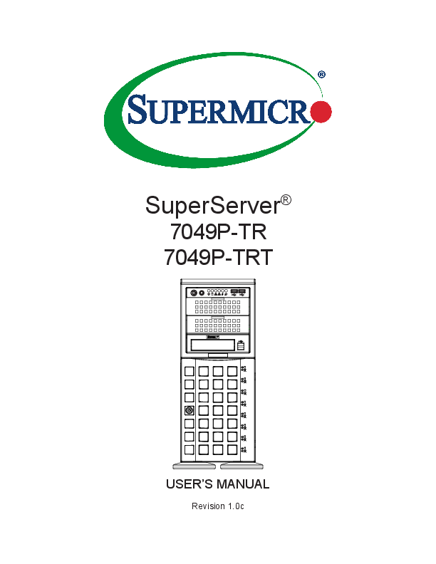
SuperServer®
7049P-TR 7049P-TRT
USER'S MANUAL
Revision 1.0c
The information in this User's Manual has been carefully reviewed and is believed to be accurate. The vendor assumes no responsibility for any inaccuracies that may be contained in this document, and makes no commitment to update or to keep current the information in this manual, or to notify any person or organization of the updates. Please Note: For the most up-to-date version of this manual, please see our website at www.supermicro.com.
Super Micro Computer, Inc. ("Supermicro") reserves the right to make changes to the product described in this manual at any time and without notice. This product, including software and documentation, is the property of Supermicro and/ or its licensors, and is supplied only under a license. Any use or reproduction of this product is not allowed, except as expressly permitted by the terms of said license.
IN NO EVENT WILL Super Micro Computer, Inc. BE LIABLE FOR DIRECT, INDIRECT, SPECIAL, INCIDENTAL, SPECULATIVE OR CONSEQUENTIAL DAMAGES ARISING FROM THE USE OR INABILITY TO USE THIS PRODUCT OR DOCUMENTATION, EVEN IF ADVISED OF THE POSSIBILITY OF SUCH DAMAGES. IN PARTICULAR, SUPER MICRO COMPUTER, INC. SHALL NOT HAVE LIABILITY FOR ANY HARDWARE, SOFTWARE, OR DATA STORED OR USED WITH THE PRODUCT, INCLUDING THE COSTS OF REPAIRING, REPLACING, INTEGRATING, INSTALLING OR RECOVERING SUCH HARDWARE, SOFTWARE, OR DATA.
Any disputes arising between manufacturer and customer shall be governed by the laws of Santa Clara County in the State of California, USA. The State of California, County of Santa Clara shall be the exclusive venue for the resolution of any such disputes. Supermicro's total liability for all claims will not exceed the price paid for the hardware product.
FCC Statement: This equipment has been tested and found to comply with the limits for a Class A digital device pursuant to Part 15 of the FCC Rules. These limits are designed to provide reasonable protection against harmful interference when the equipment is operated in a commercial environment. This equipment generates, uses, and can radiate radio frequency energy and, if not installed and used in accordance with the manufacturer's instruction manual, may cause harmful interference with radio communications. Operation of this equipment in a residential area is likely to cause harmful interference, in which case you will be required to correct the interference at your own expense.
California Best Management Practices Regulations for Perchlorate Materials: This Perchlorate warning applies only to products containing CR (Manganese Dioxide) Lithium coin cells. "Perchlorate Material-special handling may apply. See www.dtsc.ca.gov/hazardouswaste/perchlorate".
WARNING: This product can expose you to chemicals including
!
lead, known to the State of California to cause cancer and birth
defects or other reproductive harm. For more information, go
to www.P65Warnings.ca.gov.
The products sold by Supermicro are not intended for and will not be used in life support systems, medical equipment, nuclear facilities or systems, aircraft, aircraft devices, aircraft/emergency communication devices or other critical systems whose failure to perform be reasonably expected to result in significant injury or loss of life or catastrophic property damage. Accordingly, Supermicro disclaims any and all liability, and should buyer use or sell such products for use in such ultra-hazardous applications, it does so entirely at its own risk. Furthermore, buyer agrees to fully indemnify, defend and hold Supermicro harmless for and against any and all claims, demands, actions, litigation, and proceedings of any kind arising out of or related to such ultra-hazardous use or sale.
Manual Revision 1.0c
Release Date: May 15, 2019
Unless you request and receive written permission from Super Micro Computer, Inc., you may not copy any part of this document. Information in this document is subject to change without notice. Other products and companies referred to herein are trademarks or registered trademarks of their respective companies or mark holders.
Copyright © 2016 by Super Micro Computer, Inc. All rights reserved. Printed in the United States of America
Preface
Preface
About this Manual
This manual is written for professional system integrators and PC technicians. It provides information for the installation and use of the server. Installation and maintenance should be performed by experienced technicians only. Please refer to the 7049P-TR(T) server specifications page on our website for updates on supported memory, processors and operating systems (http://www.supermicro.com).
Notes
For your system to work properly, please follow the links below to download all necessary drivers/utilities and the user's manual for your server.
· Supermicro product manuals: http://www.supermicro.com/support/manuals/ · Product drivers and utilities: https://www.supermicro.com/wftp · Product safety info: http://www.supermicro.com/about/policies/safety_information.cfm
If you have any questions, please contact our support team at: support@supermicro.com This manual may be periodically updated without notice. Please check the Supermicro website for possible updates to the manual revision level.
Warnings
Special attention should be given to the following symbols used in this manual.
Warning! Indicates important information given to prevent equipment/property damage or personal injury.
Warning! Indicates high voltage may be encountered when performing a procedure.
3
SuperServer 7049P-TR(T) User's Manual
Contents
Chapter 1 Introduction 1.1 Overview................................................................................................................................8 1.2 Unpacking the System..........................................................................................................8 1.3 System Specifications...........................................................................................................9 1.4 Server Chassis Features.....................................................................................................10
Control Panel.....................................................................................................................10 Front Features....................................................................................................................11 Rear Features....................................................................................................................12 1.5 Motherboard Layout............................................................................................................13 Quick Reference................................................................................................................14 Chapter 2 Rack Mount Installation 2.1 Overview..............................................................................................................................17 2.2 Preparing for Rack Mounting..............................................................................................17 Choosing a Setup Location................................................................................................17 Rack Precautions...............................................................................................................17 Server Precautions.............................................................................................................18 Rack Mounting Considerations..........................................................................................18
Ambient Operating Temperature.....................................................................................18 Airflow.............................................................................................................................18 Mechanical Loading........................................................................................................18 Circuit Overloading.........................................................................................................19 Reliable Ground..............................................................................................................19 2.3 Chassis Preparation............................................................................................................20 2.4 Installing the Rails...............................................................................................................21 Identifying the Rails ..........................................................................................................21 Releasing the Inner Rails...................................................................................................21 Installing the Inner Rails....................................................................................................22 Assembling and Installing the Outer Rails.........................................................................23 2.5 Installing the Server into the Rack......................................................................................24 Removing the Chassis from the Rack...............................................................................25 2.6 Control Panel Orientation....................................................................................................26
4
Contents
Chapter 3 Maintenance and Component Installation 3.1 Removing Power.................................................................................................................28 3.2 Accessing the System.........................................................................................................29 3.3 Motherboard Components...................................................................................................30
Processor and Heatsink Installation...................................................................................30 The Processor ...............................................................................................................30 The Processor Carrier Assembly....................................................................................30 Heatsinks........................................................................................................................31 Overview of the Processor Heatsink Module.................................................................32 Creating the Processor Carrier Assembly......................................................................33 Assembling the Processor Heatsink Module..................................................................34 Preparing the CPU Socket for Installation.....................................................................35 Installing the Processor Heatsink Module......................................................................36
Memory..............................................................................................................................37 Memory Support.............................................................................................................37 Memory Population Guidelines.......................................................................................38 Memory Population Sequence.......................................................................................38 Installing Memory............................................................................................................41
PCIe M.2 Slot.....................................................................................................................42 Motherboard Battery..........................................................................................................43 3.4 Chassis Components..........................................................................................................44 Storage Drives...................................................................................................................44
Drive Indicators ..............................................................................................................44 Installing the Standard 3.5" Drives.................................................................................45 Configuring the 5.25" Drive Bays.......................................................................................47 Additional Storage Drives in a Mobile Rack...................................................................50 Installing Expansion Cards................................................................................................52 System Cooling..................................................................................................................53 Chassis Fans..................................................................................................................53 Air Shroud.......................................................................................................................54 Power Supply.....................................................................................................................55 Power Supply LEDs........................................................................................................55 Removing the Front Bezel.................................................................................................56
5
SuperServer 7049P-TR(T) User's Manual
Chapter 4 Motherboard Connections 4.1 Power Connections.............................................................................................................57 4.2 Headers and Connectors....................................................................................................58
Control Panel.....................................................................................................................62 Data Cables.......................................................................................................................64 4.3 Input/Output Ports and Interface Buttons............................................................................65 4.4 Jumpers...............................................................................................................................66
Explanation of Jumpers..................................................................................................66 4.5 LED Indicators.....................................................................................................................68 Chapter 5 Software 5.1 Microsoft Windows OS Installation......................................................................................70 5.2 Driver Installation.................................................................................................................72 5.3 SuperDoctor® 5....................................................................................................................73 5.4 IPMI.....................................................................................................................................74 Chapter 6 BIOS 6.1 Introduction..........................................................................................................................75
Starting BIOS Setup Utility.................................................................................................75 6.2 Main Setup..........................................................................................................................75 6.3 Advanced Setup Configurations..........................................................................................77 6.4 Event Logs........................................................................................................................118 6.5 IPMI...................................................................................................................................120 6.6 Security..............................................................................................................................123 6.7 Boot...................................................................................................................................126 6.8 Save & Exit........................................................................................................................129 Appendix A BIOS Error Codes Appendix B Standardized Warning Statements for AC Systems Appendix C System Specifications Appendix D UEFI BIOS Recovery Appendix E Crash Dump Using IPMI Appendix F CPU-Based RAID for NVMe
6
Contacting Supermicro
Contacting Supermicro
Headquarters Address:
Tel: Fax: Email:
Website:
Super Micro Computer, Inc. 980 Rock Ave. San Jose, CA 95131 U.S.A. +1 (408) 503-8000 +1 (408) 503-8008 marketing@supermicro.com (General Information) support@supermicro.com (Technical Support) www.supermicro.com
Europe Address:
Tel: Fax: Email:
Website:
Super Micro Computer B.V. Het Sterrenbeeld 28, 5215 ML 's-Hertogenbosch, The Netherlands +31 (0) 73-6400390 +31 (0) 73-6416525 sales@supermicro.nl (General Information) support@supermicro.nl (Technical Support) rma@supermicro.nl (Customer Support) www.supermicro.nl
Asia-Pacific Address:
Tel: Fax: Email: Website:
Super Micro Computer, Inc. 3F, No. 150, Jian 1st Rd. Zhonghe Dist., New Taipei City 235 Taiwan (R.O.C) +886-(2) 8226-3990 +886-(2) 8226-3992 support@supermicro.com.tw www.supermicro.com.tw
7
SuperServer 7049P-TR(T) User's Manual
Chapter 1 Introduction
1.1 Overview
This chapter provides a brief outline of the functions and features of the 7049P-TR(T). The 7049P-TR(T) is based on the X11DPi-N(T) motherboard and the SC745BAC-R1K28B chassis. The server offers two network ports:
· The 7049P-TR model supports 1 Gbps.
· The 7049P-TRT model supports 10 Gbps.
In addition to the motherboard and chassis, several included parts are listed below.
Description Power Supply SAS/SATA hard drive backplane Heatsink (passive) Rear exhaust fans Mid-chassis fans Air shroud Carriers for hot-swap hard drives Chassis rail kit (optional)
Main Parts List Part Number
PWS-1K28P-SQ BPN-SAS3-743A SNK-P0068PS FAN-0180L4 FAN-0182L4 MCP-310-49001-0N MCP-220-00092-0B CSE-PT26L-B
Quantity 2 1 2 2 3 1 8 1
1.2 Unpacking the System
Inspect the box the server was shipped in and note if it was damaged in any way. If any equipment appears damaged, file a damage claim with the carrier who delivered it.
8
Chapter 1: Introduction
1.3 System Specifications
The following provides an overview of the main features.
System Specifications Motherboard
X11DPi-N (7049P-TR), X11DPi-NT (7049P-TRT)
Chassis SC745BAC-R1K28B
CPU Dual Intel Xeon 82xx/62xx/52xx/42xx/32xx or 81xx/61xx/51xx/41xx/31xx processors (in Socket P (LGA3647)) (Intel Xeon Processor Scalable Family). For the latest CPU/memory updates, refer to our website at http://www.supermicro.com/products/motherboard/Xeon/C620/X11DPi-N.cfm. Memory Supports up to 4 TB of 3DS LRDIMM/LRDIMM/3DS RDIMM/RDIMM/NV-DIMM DDR4 (288-pin) ECC up to 2933 MHz modules in 16 slots; up to 256 GB size; support for Non-Volatile DIMM (NVDIMM) and Intel Optane DC Persistent Memory (DCPMM) Notes: 1. Up to 5TB of memory is supported with DCPMM modules installed.
2. 2933 MHz speed is supported by 82xx/62xx processors only Chipset Intel C621 or C622 series
Expansion Slots Six PCI-Express 3.0 slots: four x16 and two x8
Input/Output Network: Two LAN ports--7049P-TR model 1 Gbps, or 7049P-TRT model 10 Gbps IPMI: One dedicated LAN port USB: Two USB 3.0 ports, two USB 2.0 port, additional ports optional COM: One VGA: One Optional addtional drives and I/O ports available as kits Storage Drives Up to eight SATA3 3.5" hot-swap drives, or optionally, 2.5" drives with converters
Power Redundant 1000/1280 W power supply, 80Plus Platinum level
Cooling Three 8-cm 11K RPM, 4-pin PWM mid-chassis fans; two 8-cm exhaust fans; one airflow shroud, two CPU heatsinks Form Factor 4U Tower; Dimensions (WxHxD) 7.0 x 19 x 27 in. (178 x 483 x 686 mm)
9
SuperServer 7049P-TR(T) User's Manual
1.4 Server Chassis Features
Control Panel
The switches and LEDs located on the control panel are described below. See Chapter 4 for details on the control panel connections.
345678
9
10
Item
1
2 3 4 5 6 7 8 9 10
1
2
Figure 1-1. Control Panel View
Feature
Power Button
Reset Button Power LED HDD LED NIC1 LED NIC2 LED Information LED Power Fail LED USB0 Port USB1 Port
Control Panel Features Description
The main power button is used to apply or remove power from the power supply to the server. Turning off system power with this button removes the main power but maintains standby power. To perform many maintenance tasks, you should also unplug the system's AC power cord before servicing. The reset button is used to reboot the system. Indicates power is being supplied to the system power supply. This LED should normally be illuminated when the system is operating. Indicates hard drive activity when flashing.
Indicates network activity on LAN port 1 when flashing.
Indicates network activity on LAN port 2 when flashing.
See table below for details. This LED flashes to indicate one of the redundant power supply modules has failed. The flashing light should be accompanied by an audible warning. USB 3.0 port
USB 3.0 port
Information LED
Status
Continuously on and red Blinking red (1Hz) Solid blue
Blinking blue
Description
An overheat condition has occurred. (This may be caused by cable congestion.) Fan failure, check for an inoperative fan. Local UID has been activated. Use this function to locate the server in a rackmount environment. Remote UID is on. Use this function to identify the server from a remote location.
10
Chapter 1: Introduction
Front Features
The SC745BAC-R1K28B is a tower chassis. See the illustration below for the features included on the front of the chassis.
1 2 2 2
3
5
4
Item
1 2 3 4 5
Figure 1-2. Chassis Front View
Feature
Control Panel Peripheral Drive Bays Lock Drive Bays Drive Indicators
Front Chassis Features Description
Front control panel with LEDs and buttons (see preceding page) Three 5.25" bays for optional peripherals such as a DVD drive Front bezel lock Eight 3.5" bays for hot-swap hard drives behind front bezel Eight pairs of LED status indicators for drives
11
SuperServer 7049P-TR(T) User's Manual
Rear Features
The illustration below shows the features included on the rear of the chassis.
1
3 2
4
Item
1 2 3 4
Feature
Power Supply I/O Back Panel Fans Expansion Slots
Figure 1-3. Chassis Rear View
Rear Chassis Features Description
Redundant 1280 W Platinum Level Power Supplies Rear I/O ports (see Section 4.3) Two 8-cm exhaust fans Six PCI-Express expansion card slots
12
Chapter 1: Introduction
1.5 Motherboard Layout
Below is a layout of the X11DPi-N(T) with jumper, connector and LED locations shown. See the table on the following pages for descriptions. For detailed descriptions, pinout information and jumper settings, refer to Chapter 4.
JPG1
IPMI LAN
SLOLTE1DMS1LSOLTO2T3BT1SLOTS4LOSTL5OT6FANL6E1UUIDID
VGFAAN5 LAN2
LAN1 USB4/5
USB0/1
COM1
LE1
VGA
COM1
JPG1
BMC LEDM1
LAN CTRL FAN6
FAN5 LAN2
LAN1
USB0/1
(2.0) IPMI_LAN USB4/5 (3.0)
JPL1
JPCIE6
CPU2 SLOT6 PCI-E 3.0 X16
JPCIE5 CPU2 SLOT5 PCI-E 3.0 X16 JPCIE4 CPU2 SLOT4 PCI-E 3.0 X16
JPCIE3
CPU1 SLOT3 PCI-E 3.0 X8
JPCIE2
JNVI2C2
CPU1 SLOT2 PCI-E 3.0 X16MAC CODE BAR CODE
JPCIE1
CPU1 SLOT1 PCI-E 3.0 X8
COM2 JIPMB1
COM2 JIPMB1
P2-DIMMD2 P2-DIMMD1 P2-DIMME1 P2-DIMMF1
CPU2
BIOS LICENSE
JVRM1 JVRM2
JPME2
JPME2
BT1
USB 2/3 (2.0)
USB2/3
(3.0)
USB6
CPU2
P2-DIMMC1
P2-DIMMB1
P2-DIMMA1
P2-DIMMA2
JP4
USB 6
USB 7/8(3.0)
JM2_1
USB7/8 LE3
JTPM1 JBT1 JD1
JTPM1
JP2
A
JHFI2 JM2_1 M.2-PCH
LE3 JBT1 JHFI1
BIOS
X11DPi-N(T)
Rev. 1.21
P2-DIMMA2 P2-DIMMA1 P2-DIMMB1 P2-DIMMC1
P1-DIMMC1 P1-DIMMB1 P1-DIMMA1 P1-DIMMA2
P2-DIMMF1 P2-DIMME1 P2-DIMMD1 P2-DIMMD2
JPI2C1
JPI2C1
P1-DIMMD2 P1-DIMMD1 P1-DIMME1 P1-DIMMF1
JPME1 JD1
T-SGPIO3
JWD1JRK1
T-SGPIO3
JWD1
JRK1
S-SATA0-3
CPU1
S-SATA 0~3 I-SATA 0~3 I-SATA 4~7 FANA FANB
PCH
I-SATA0-3
I-SATA4-7
FAN3 FAN4
JL1 FANB
JL1 JNVI2C1
S-SATA5
JSTBY1
FANA
S-SATA4 JNVME2 JNVME1
JSTBY1 S-SAST-AS4ATA5
JNVI2C1 JNVME2
P1-DIMMD2 JNVFMAENF14ANP31-DIPM1M-PDF1I1M-DMIMEM1 D1
CPU1
JPWR1 JPWR2
JPWR1
JPWR2
P1-DIMMA2
P1-DIMMA1
P1-DIMMB1
JF1
P1-DIMMC1
JPWR3
JF1
A C
LE2
JPWR3 LE2
FAN2 FAN1
FAN2 FAN1
= mounting hole
Figure 1-4. Motherboard Layout Notes:
· " " indicates the location of pin 1.
· Jumpers/LED indicators not indicated are used for testing only.
13
SuperServer 7049P-TR(T) User's Manual
Quick Reference
Jumper
Description
JBT1
CMOS Clear
JPG1
VGA Enable
JPME2
Manufacturing Mode Select
JWD1
Watch Dog Timer Enable
Default Setting
Open (Normal) Pins 1-2 (Enabled) Pins 1-2 (Normal) Pins 1-2 (Reset to System)
Connector
BT1 COM1/COM2 FAN1-6, FANA/FANB IPMI_LAN I-SATA0~3, I-SATA4~7 JD1 JF1
JHFI1/JHFI2
JIPMB1 JL1 JM2_1
JNVI2C1/JNVI2C2
JNVME1 JNVME2 JPI2C1 JPWR1/JPWR2 JPWR3 JRK1 JSTBY1 JTPM1
LAN1/LAN2
S-SATA0-3
S-SATA4/S-SATA5
SLOT1/SLOT3 SLOT2 SLOT4/SLOT5/SLOT6 T-SGPIO3 UID USB0/1 USB2/3 USB4/5
Description
Onboard CMOS battery socket Back panel COM port/COM header for front access System cooling fan headers (FAN1-FAN6, FAN A, FAN B) Dedicated IPMI_LAN port SATA 3.0 iPass header supported by the Intel PCH Power LED header Front Panel Control header Host Fabric Interface (HFI) sideband connection headers used for the HFI carrier cards (when the SKX-F processors are used.) (JHFI1: for CPU1, JHFI2: for CPU2). 4-pin BMC External I2C header (for an IPMI-supported card) Chassis Intrusion header PCIe M.2 slot NVMe I2C headers used for PCIe hot-plug SMBus clock and data connections (a proprietary NVMe add-on card and cable are required; available for a Supermicro complete system only) NVMe Connector1 NVMe Connector2 Power Supply SMBbus I2C header 8-pin Power Supply connectors 24-pin ATX main power supply connector Intel RAID Key headier for NVMe SSD Standby power header Trusted Platform Module (TPM)/Port 80 connector Gigabit LAN/10G LAN Ethernet Ports on the IO back panel (10G LAN ports on X11DPi-NTX11DPi-N(T) only) S-SATA 3.0 iPass header supported by the Intel SCU S-SATA Ports with built-in power pins and with support of Supermicro SuperDOM (Disk On Module) devices PCI-Express 3.0 X8 Slots supported by CPU1 PCI-Express 3.0 X16 Slot supported by CPU1 PCI-Express 3.0 X16 Slots supported by CPU2 General Purpose Serial I/O Port Unit Identifier (UID) Switch Back panel USB 2.0 Ports Front Accessible USB 2.0 Header Back panel USB 3.0 Ports
14
Chapter 1: Introduction
Connector
USB6 USB7/8 VGA
LED
LE1 LE2 LE3 LEDM1
Description
Type A USB 3.0 Header Front Accessible USB 3.0 Header VGA Port
Description
UID (Unit Identifier) LED Onboard Power LED M.2 Active LED BMC Heartbeat LED
State: Status
Solid Blue: Unit identified On: Onboard power on On: M.2 active Blinking Green: BMC normal
15
SuperServer 7049P-TR(T) User's Manual
PCI-E X16 PCI-E X16 DDR4 2133/2666 PCI-E X16 P2-DIMMA1 P2-DIMMA2 P2-DIMMB1 P2-DIMMC1 P2-DIMMD1 P2-DIMMD2 P2-DIMME1 P2-DIMMF1
DDR4 2133/2666 P1-DIMMA1 P1-DIMMA2 P1-DIMMB1 P1-DIMMC1 P1-DIMMD1 P1-DIMMD2 P1-DIMME1 P1-DIMMF1
SLOT 2
VCCP0
P0
DDR4 PECI : 30 P1
SOCKET I D: 0 #2 #1A #1B #3A #3B DMI 3
P1
UPI
VCCP1
P0
UPI
DDR4
PECI : 31 SOCKET I D: 1
#1 #2 #3 DMI 2
PCI-E X8 PCI-E X16
PCI-E X8 G3
PCI-E X16 G3 (LANE REVERSE)
SLOT 1
PCI-E X8 G3 PCI-E X8 G3
PCI-E X8
SLOT 3
2 x NVME PCI-E X8 G3
LAN 10G/1G
(QAT NOT SUPPORT)
X557/88E1512
(*X11DPi supports GLAN ports)
KR/KX
(*X11DPi-T supports 10G LAN
ports)
DMI3
#3 PCH
PCI-E X16 G3
PCI-E X16 G3 PCI-E X16 G3
SLOT 4
(LANE REVERSE)
SLOT 6 SLOT 5
#9 #7#8 #5#6 #3#4 #2 #0#1
6.0 Gb/S
#11 #10
SATA
SATA
USB
USB
RJ45
DDR4 BMC Boot Flash
LAN3
RGRMII
RTL8211E-VB-CG
SPI
BMC
AST2500
RMII/NCSI
PCI-E X1 G2 USB 2.0 ESPI
#2 LBG-2 X8 UPLINK NO QAT (14W)
USB 2.0
#5
#12 USB2.0 LLBBGG--21GX8XU1PULPINLKINNKONQOAQTA(T17(1W5)W) LBG-4 X16 UPLINK NO QAT (19W) LBG-E X16 UPLINK QAT (21W) LBG-M X16 UPLINK QAT (26W) LBG-L X16 UPLINK QAT (21W) LBG-T X16 UPLINK QAT (29W)
USB 3.0
SPI
VGA CONN
COM1 Connector
COM2 Header
TPM HEADER Debug Card
BIOS
Temp Sensor W83773 at SMBUS
Figure 1-5. Intel C621 or C622 series Chipset: System Block Diagram
Note: This is a general block diagram and may not exactly represent the features on your motherboard. See the System Specifications appendix for the actual specifications of your motherboard.
16
Chapter 2: Rack Mount Installation
Chapter 2
Rack Mount Installation
2.1 Overview
This chapter provides instructions for preparing and mounting your chassis in a rack. By default, the chassis is shipped configured as a tower. The tower top cover and bottom feet must be removed to mount in a rack. Also, the control panel/drive module should be rotated 90 degrees. Mounting rails are optional for this system. Be sure you have received the correct rail kit for your server.
2.2 Preparing for Rack Mounting
Choosing a Setup Location · The system should be situated in a clean, dust-free area that is well ventilated. Avoid areas
where heat, electrical noise and electromagnetic fields are generated.
· Leave at least 25 inches clearance in front of the rack to open the front door completely. · Leave approximately 30 inches of clearance in the back of the rack to allow for sufficient
airflow and access for servicing.
· It should be a restricted access location, such as a dedicated equipment room or a service
closet.
· This product is not suitable for use with visual display workplace devices acccording to §2
of the German Ordinance for Work with Visual Display Units.
Rack Precautions · Ensure that the leveling jacks on the bottom of the rack are extended to the floor so that
the full weight of the rack rests on them.
· In single rack installations, stabilizers should be attached to the rack. In multiple rack in-
stallations, the racks should be coupled together.
· Always make sure the rack is stable before extending a server or other component from
the rack.
17
SuperServer 7049P-TR(T) User's Manual
· You should extend only one server or component at a time; extending two or more simul-
taneously may cause the rack to become unstable.
· When initially installing the server to a rack, test that the rail locking tabs engage to prevent
the server from being overextended. Have a rack lift in place as a precaution in case the test fails.
Server Precautions · Review the electrical and general safety precautions in Appendix B. · Determine the placement of each component in the rack before you install the rails. · Install the heaviest server components at the bottom of the rack first and then work your
way up.
· Use a regulating uninterruptible power supply (UPS) to protect the server from power
surges and voltage spikes and to keep your system operating in case of a power failure.
· Allow any drives and power supply modules to cool before touching them. · When not servicing, always keep the front door of the rack and all covers/panels on the
servers closed to maintain proper cooling.
Rack Mounting Considerations
Ambient Operating Temperature If installed in a closed or multi-unit rack assembly, the ambient operating temperature of the rack environment may be greater than the room's ambient temperature. Therefore, consideration should be given to installing the equipment in an environment compatible with the manufacturer's maximum rated ambient temperature (TMRA).
Airflow Equipment should be mounted into a rack so that the amount of airflow required for safe operation is not compromised.
Mechanical Loading Equipment should be mounted into a rack so that a hazardous condition does not arise due to uneven mechanical loading.
18
Chapter 2: Rack Mount Installation
Circuit Overloading Consideration should be given to the connection of the equipment to the power supply circuitry and the effect that any possible overloading of circuits might have on overcurrent protection and power supply wiring. Appropriate consideration of equipment nameplate ratings should be used when addressing this concern.
Reliable Ground A reliable ground must be maintained at all times. To ensure this, the rack itself should be grounded. Particular attention should be given to power supply connections other than the direct connections to the branch circuit (i.e. the use of power strips, etc.).
To prevent bodily injury when mounting or servicing this unit in a rack, you must take special precautions to ensure that the system remains stable. The following guidelines are provided to ensure your safety:
· This unit should be mounted at the bottom of the rack if it is the only unit in the rack. · When mounting this unit in a partially filled rack, load the rack from the bottom to the top
with the heaviest component at the bottom of the rack.
· If the rack is provided with stabilizing devices, install the stabilizers before mounting or
servicing the unit in the rack.
· Slide rail mounted equipment is not to be used as a shelf or a work space.
19
SuperServer 7049P-TR(T) User's Manual
2.3 Chassis Preparation
The chassis is shipped with the tower top cover and feet installed. Both must be removed for before installing the rails.
Removing the Tower Top Cover 1. Locate the chassis cover lock (blue lever) at the rear of the chassis cover.
2. Slide the chassis cover lock to the right and push chassis cover forward.
3. Lift the chassis top cover off the chassis.
Tower Top Cover
Chassis Feet
Chassis Cover Lock
Figure 2-1. Remove Feet and Chassis Top Cover
Removing the Chassis Feet 1. Place the chassis on its side. 2. Remove the screw holding a chassis foot in place. 3. The foot lock is a tab located in the center of the foot. It prevents the foot from sliding.
Using a flat head screwdriver, gently lift the foot lock upward and slide the foot toward the rear of the chassis.
20
Chapter 2: Rack Mount Installation
2.4 Installing the Rails
There are a variety of rack units on the market, which may require a slightly different assembly procedure. Do not use a two post "telco" type rack. This rail set fits a rack between 26" and 35.9" deep. The following is a basic guideline for installing the system into a rack with the rack mounting hardware provided. You should also refer to the installation instructions that came with the specific rack you are using.
Identifying the Rails
The optional rackmount kit includes two rack rail assemblies, one for each side. Each of these assemblies consist of several sections: an inner fixed rail that secures to the chassis, an outer rack rail that secures to the rack, a middle rail that slides within the outer rail, and two brackets that attach the outer rail to the rack. The brackets are specific to the left and right side, and front and back, and labeled.
Inner rail
Outer rail
Rail brackets
Figure 2-2. Identifying the Sections of the Rack Rails
Releasing the Inner Rails
The inner rails must be removed from the outer rails to install onto the chassis. To remove the inner rail, pull it out as far as possible until it clicks to a stop. Depress the locking lever on the inner rail next to the middle rail to pull the inner rail completely out.
21
SuperServer 7049P-TR(T) User's Manual
Installing the Inner Rails
Identify the left and right inner rails. 1. Attach the handles to the front sides of the chassis with three screws each. 2. Position the inner rails along the side of the chassis making sure the screw holes line
up. 3. Screw the rail securely to the side of the chassis.
Screw for Handles Screw for Inner Rails
Figure 2-3. Installing the Chassis Rails Warning: Do not pick up the server with the front handles. They are designed to pull the system from a rack only.
22
Chapter 2: Rack Mount Installation
Assembling and Installing the Outer Rails
Each outer rail comes in three sections that require assembly before mounting onto the rack. 1. Find the outer rail mounting brackets in the chassis accessory box.
· A pair of long brackets for the rear of each rail · A pair of short brackets for the front of each rail
Note that the brackets are labeled as to front, rear, and up. They are specific for the left and right rails. 2. Secure the front (short) bracket onto the outer rail with M5 screws. 3. Mount the rear (long) bracket onto the outer rail at the approximate position to fit your rack. Use two or three M5 screws into holes that are convenient. Leave the screws just loose enough that the bracket can slide. 4. Install the outer rail assembly onto your rack. Adjust the outer rail to the exact depth of the rack by sliding the rear bracket. Then use screws and fasteners to secure the outer rail to the front and rear rack posts. 5. Further tighten the screws holding the rear bracket to the rail.
4
3
2 4
Screw for Outer Rail Brackets
Figure 2-4. Assembling the Outer Rails
23
SuperServer 7049P-TR(T) User's Manual
2.5 Installing the Server into the Rack
After attaching rails to both the chassis and the rack, slide the server into the rack. 1. Pull the middle rail out of the front of the outer rail and make sure that the ball bearing
shuttle is locked at the front of the middle rail. 2. Align the rear of the inner (chassis) rails with the front of the outer (rack) rails and slide
the inner rails into the outer rails until the server is completely in the rack. 3. Insert and tighten the thumbscrews that hold the front of the server to the rack.
Figure 2-5. Installing the Server into a Rack Note: Figure is for illustrative purposes only. Always install servers to the bottom of a rack first.
Warning: Stability hazard. The rack stabilizing mechanism must be in place, or the rack must be bolted to the floor before you slide the unit out for servicing. Failure to stabilize the rack can cause the rack to tip over. When initially installing the server to a rack, test that the rail locking tabs engage to prevent the server from being overextended. Have a rack lift in place as a precaution in case the test fails.
24
Chapter 2: Rack Mount Installation
Removing the Chassis from the Rack
Caution! It is dangerous for a single person to off-load the heavy chassis from the rack without assistance. Be sure to have sufficient assistance supporting the chassis when removing it from the rack. Use a lift. 1. Pull the chassis forward out the front of the rack until it stops. 2. Find the release lever on each side of the chassis on the inner rails. Release the
chassis by simultaneously and lifting the left lever and pushing down the right lever. Continue to pull the chassis out of the rack.
Warning: In any instance of pulling the system from the rack, always use a rack lift and follow all associated safety precautions. Slide rail mounted equipment is not to be used as a shelf or a work space.
25
SuperServer 7049P-TR(T) User's Manual
2.6 Control Panel Orientation
The server can be configured for either tower or server rack orientation. It is shipped in tower mode and can be immediately used as desktop server. To use it in a rack, rotate the module that contains the control panel and the three drive trays ( 1 in Figure 2-6) 90 degrees. Note that two of the 5.25" drives may be replaced by a mobile rack containing eight 2.5" storage drives.
Control Panel 5.25" Drive Trays
Default Hard Disk Drive Bays
1
Control Panel/ Drive Module
Figure 2-6. Chassis in Tower Mode (Default Configuration)
Control Panel/ Drive Module
1
Figure 2-7. Chassis in Rack Mount Mode
26
Chapter 2: Rack Mount Installation
Rotating the Control Panel/Drive Module for Rack Mounting 1. Power down the system as described in section 3.1 and open the chassis cover. 2. Disconnect any cables from the back of the Control Panel/Drive Module. 3. Push the module release lever to unlock the module.
Control Panel/ Drive Module in Rack Mount Orientation
3
Module Release Lever
Figure 2-8. Rotating the Control Panel/Drive Module 4. Grasp the edges of the module and pull it from the chassis. 5. Rotate the module 90 degrees so that the control panel is on top. 6. Reinsert the module into the chassis and reconnect the cables. Caution: Use caution when working around the backplane. Do not touch the module backplane with any metal objects and make sure no ribbon cables touch the backplane or obstruct the holes, which aid in proper airflow.
27
SuperServer 7049P-TR(T) User's Manual
Chapter 3 Maintenance and Component Installation
This chapter provides instructions on installing and replacing main system components. To prevent compatibility issues, only use components that match the specifications and/or part numbers given. Installation or replacement of most components require that power first be removed from the system. Please follow the procedures given in each section.
3.1 Removing Power
Use the following procedure to ensure that power has been removed from the system. This step is necessary when removing or installing non-hot-swap components. 1. Use the operating system to power down the system. 2. After the system has completely shut down, disconnect both the AC power cords from
the power strip or outlet. 3. Disconnect the power cords from both the power supply modules.
28
Chapter 3: Maintenance and Component Installation
3.2 Accessing the System
The chassis offers a removable side cover (top, if rack mounted) which allows access to the internal components. Removing the Side Cover 1. Locate the latch on the cover, depress where it says "push," then lift the latch to release
the cover. 2. Slide the cover to the rear and off.
Release Latch
Figure 3-1. Removing the Chassis Cover 29
SuperServer 7049P-TR(T) User's Manual
3.3 Motherboard Components
Processor and Heatsink Installation
The processor (CPU) and processor carrier should be assembled together first to form the processor carrier assembly. This will be attached to the heatsink to form the processor heatsink module (PHM) before being installed onto the CPU socket. Notes:
· Use ESD protection. · Unplug the AC power cord from all power supplies after shutting down the system. · Check that the plastic protective cover is on the CPU socket and none of the socket pins
are bent. If they are, contact your retailer.
· When handling the processor, avoid touching or placing direct pressure on the LGA lands
(gold contacts). Improper installation or socket misalignment can cause serious damage to the processor or CPU socket, which may require manufacturer repairs.
· Thermal grease is pre-applied on a new heatsink. No additional thermal grease is needed. · Refer to the Supermicro website for updates on processor support. · All graphics in this manual are for illustration only. Your components may look different.
The Processor The Intel Xeon 82xx/62xx/52xx/42xx/32xx or 81xx/61xx/51xx/41xx/31xx processor series comes in two models: Fabric (F Model) and Non-Fabric (Non-F Model). Only the Non-Fabric model is supported for this system.
The Processor Carrier Assembly The assembly is the processor and a plastic carrier.
Processor
Processor Carrier
Figure 3-2. Processor and Carrier 30
Chapter 3: Maintenance and Component Installation
Heatsinks The 7049P-TR(T) server uses a slightly different heatsink design for each CPU. The SNKP0068PSC model is used for CPU1, the CPU closer to the mid-chassis fans.
Figure 3-3. Heatsink SNK-P0068PSC (for CPU1)
Figure 3-4. Heatsink SNK-P0068PS (for CPU2)
Note: For CPU1, the SNK-P0068PSC heatsink must be installed with the side with short fins facing the power supply modules.
31
SuperServer 7049P-TR(T) User's Manual Overview of the Processor Heatsink Module
The Processor Heatsink Module (PHM) contains a heatsink, a processor carrier, and the processor. Note that there are two different heatsink models, SNK-P0068PS and SNKP0069PS (not as tall).
Heatsink with Thermal Grease
Processor Carrier
Processor
Processor Heatsink Module
Bottom View
32
Chapter 3: Maintenance and Component Installation
Creating the Processor Carrier Assembly To install a processor into the processor carrier, follow the steps below: 1. Hold the processor with the LGA lands (gold contacts) facing up. Locate the small, gold
triangle in the corner of the processor and the corresponding hollowed triangle on the processor carrier. These triangles indicate pin 1. See the images below.
2. Using the triangles as a guide, carefully align and place Point A of the processor into Point A of the carrier. Then gently flex the other side of the carrier for the processor to fit into Point B.
3. Examine all corners to ensure that the processor is firmly attached to the carrier.
CPU (Upside Down) with CPU LGA Lands up
A
Align Point A of the CPU and Point A of the Processor Carrier
Align CPU Pin 1
B
Align Point B of the CPU and
Point B of the Processor Carrier
Pin 1
B
A
Processor Carrier (Upside Down)
Allow carrier to latch onto CPU
B
A
Allow carrier to latch onto CPU
Pin 1
33
SuperServer 7049P-TR(T) User's Manual
Assembling the Processor Heatsink Module After creating the processor carrier assembly, mount it onto the heatsink to create the processor heatsink module (PHM): 1. Note the label on top of the heatsink, which marks the heatsink mounting holes as 1,
2, 3, and 4. If this is a new heatsink, the thermal grease has been pre-applied on the underside. Otherwise, apply the proper amount of thermal grease.
2. Turn the heatsink over with the thermal grease facing up. Hold the processor carrier assembly so the processor's gold contacts are facing up, then align the triangle on the assembly with hole 1 of the heatsink. Press the processor carrier assembly down. The plastic clips of the assembly will lock outside of holes 1 and 2, while the remaining clips will snap into their corresponding holes.
3. Examine all corners to ensure that the plastic clips on the processor carrier assembly are firmly attached to the heatsink.
Non-Fabric Processor Carrier Assembly
(Upside Down)
2
Triangle on the CPU
12
Triangle on the Processor Carrier
Heatsink (Upside Down) 1
2
Remaining plastic clips snap into the other corner holes of the heatsink
1
Plastic clips 1 and 2 lock outside the heatsink's mounting holes
34
Chapter 3: Maintenance and Component Installation Preparing the CPU Socket for Installation This motherboard comes with a plastic protective cover on the CPU socket. Remove it carefully to install the Processor Heatsink Module (PHM).
CPU Socket with Plastic Protective Cover
Remove the plastic protective cover from the CPU socket. Do not touch or bend the socket pins. Socket Pins
35
SuperServer 7049P-TR(T) User's Manual
Installing the Processor Heatsink Module After assembling the Processor Heatsink Module (PHM), install it onto the CPU socket: Note that there are two different heatsink models, SNK-P0067PS and SNK-P0067PSM. Use the SNK-P0067PSM for CPU2 in each node. 1. Align hole 1 of the heatsink with the printed triangle on the CPU socket. See the left
image below. 2. Make sure all four holes of the heatsink are aligned with the socket before gently placing
the heatsink on top. 3. With a T30 Torx-bit screwdriver, gradually tighten screws #1 #4 to assure even
pressure. The order of the screws is shown on the label on top of the heatsink. To avoid damaging the processor or socket, do not use a force greater than 12 lbf-in when tightening the screws. 4. Examine all corners to ensure that the PHM is firmly attached to the socket.
Oval C
Oval D
Large Guide Post
Use a torque of 12 lbf-in
T30 Torx Screwdriver
#4
#1
#2
Small Guide Post
Printed Triangle Mounting the Processor Heatsink Module onto the CPU socket (on the motherboard)
#3
Tighten the screws in the sequence of 1, 2, 3, 4
If at any time the PHM must be removed, power off, then loosen the screws in the sequence of #4, #3, #2, and #1.
36
Chapter 3: Maintenance and Component Installation
Memory
Memory Support The 7049P-TR(T) has sixteen slot supporting up to 4TB of 3DS Load Reduced DIMM (3DS LRDIMM), Load Reduced DIMM (LRDIMM), 3DS Registered DIMM (3DS RDIMM), Registered DIMM (RDIMM), Non-Volatile DIMM (NV-DIMM) DDR4 (288-pin) ECC up to 2933 MHz memory modules. In addition it supports Non-Volatile DIMMs (NV-DIMM) and Intel Optane DC Persistent Memory (DCPMM).Memory speed is dependent on the processor model.
DDR4 Memory Support for 81xx/61xx/51xx/41xx/31xx Processors
Type
Ranks Per DIMM and Data Width
DIMM Capacity (GB)
DRAM Density 4 Gb 8 Gb
One Slot per Channel One DIMM per Channel 1.2 Volts
Speed (MT/s)
Two Slots per Channel
One DIMM Two DIMMs per Channel per Channel
1.2 Volts
1.2 Volts
SRx4
4 GB
8 GB
RDIMM
SRx8 DRx8
8 GB 8 GB
16 GB 16 GB
DRx4
16 GB 32 GB
QRX4
N/A
RDIMM 3Ds
8RX4
N/A
2H-64GB 4H-128GB
2666
2666
2666
LRDIMM
QRx4
32 GB 64 GB
QRx4
N/A
LRDIMM 3Ds
8Rx4
N/A
2H-64GB 4H-128 GB
DDR4 Memory Support for 82xx/62xx/52xx/42xx/32xx Processors
Type
Ranks Per DIMM and Data Width
DIMM Capacity (GB)
DRAM Density
4 Gb* 8 Gb
16 Gb
Speed (MT/s)
One Slot per Channel
Two Slots per Channel
One DIMM One DIMM Two DIMMs per Channel per Channel per Channel
1.2 Volts
1.2 Volts
1.2 Volts
SRx4
4 GB 8 GB
16 GB
RDIMM
SRx8 DRx8
8 GB 8 GB
16 GB 16 GB
32 GB 32 GB
DRx4
16 GB 32 GB
64 GB
QRX4 N/A 2H-64GB 2H-128GB 2933**
RDIMM 3Ds
8RX4
N/A
4H-128GB 4H-256GB
2933**
2933**
LRDIMM
QRx4
32 GB 64 GB
128 GB
QRx4
N/A
2H-64GB 2H-64GB
LRDIMM 3Ds
8Rx4
N/A 4H-128 GB 4H-256 GB
*4Gb DRAM density is only supported on speeds up to 2666 MT/s **Only the 82xx and 62xx series support 2933 MT/s; for other processors, memory speed as supported by the CPU.
Check the Supermicro website for possible updates to memory support.
37
SuperServer 7049P-TR(T) User's Manual
Memory Population Guidelines
· All DIMMs must be DDR4. · Balance memory. Using unbalanced memory topology, such as populating two DIMMs in
one channel while populating one DIMM in another channel, reduces performance. It is not recommended for Supermicro systems.
· In dual-CPU configurations, memory must be installed in the slots associated with the
installed CPUs.
Guidelines Regarding Mixing DIMMs
· Populating slots with a pair of DIMM modules of the same type and size results in inter-
leaved memory, which improves memory performance.
· Use memory modules of the same type and speed, as mixing is not allowed. · x4 and x8 DIMMs can be mixed in the same channel. · Mixing of LRDIMMs and RDIMMs is not allowed in the same channel, across different
channels, and across different sockets.
· Mixing of non-3DS and 3DS LRDIMM is not allowed in the same channel, across different
channels, and across different sockets.
DIMM Construction
· RDIMM (non-3DS) Raw Cards: A/B (2Rx4), C (1Rx4), D (1Rx8), E (2Rx8) · 3DS RDIMM Raw Cards: A/B (4Rx4) · LRDIMM (non-3DS) Raw Cards: D/E (4Rx4) · 3DS LRDIMM Raw Cards: A/B (8Rx4)
Memory Population Sequence Blue slots versus black slots: Install the first DIMM in the blue memory slot, which is the first of a memory channel. Then, if using two DIMMs per channel, install the second DIMM in the black slot. The following memory population sequence table was created based on guidelines provided by Intel to support Supermicro motherboards. The diagram is for illustrative purposes; your motherboard may look different.
38
Chapter 3: Maintenance and Component Installation
CPUs/DIMMs 1 CPU & 1 DIMM 1 CPU & 2 DIMMs 1 CPU & 3 DIMMs 1 CPU & 4 DIMMs 1 CPU & 5 DIMMs* 1 CPU & 6 DIMM 1 CPU & 7 DIMMs* 1 CPU & 8 DIMMs*
2 CPUs & 2 DIMMs
2 CPUs & 4 DIMMs
2 CPUs & 6 DIMMs
2 CPUs & 8 DIMMs
2 CPUs & 10 DIMMs
2 CPUs & 12 DIMMs
2 CPUs & 14 DIMMs*
2 CPUs & 16 DIMMs*
Memory Population Table, 16 DIMM Slots
Memory Population Sequence CPU1: P1-DIMMA1 CPU1: P1-DIMMA1/P1-DIMMD1 CPU1: P1-DIMMC1/P1-DIMMB1/P1-DIMMA1 CPU1: P1-DIMMB1/P1-DIMMA1/P1-DIMMD1/P1-DIMME1 CPU1: P1-DIMMC1/P1-DIMMB1/P1-DIMMA1/P1-DIMMD1/P1-DIMME1 CPU1: P1-DIMMC1/P1-DIMMB1/P1-DIMMA1/P1-DIMMD1/P1-DIMME1/P1-DIMMF1 CPU1:P1-DIMMC1/P1-DIMMB1/P1-DIMMA1/P1-DIMMA2/P1-DIMMD1/P1-DIMME1/P1-DIMMF1 CPU1: P1-DIMMC1/P1-DIMMB1/P1-DIMMA1/P1-DIMMA2/P1-DIMMD2/P1-DIMMD1/P1-DIMME1/P1DIMMF1 CPU1: P1-DIMMA1 CPU2: P2-DIMMA1 CPU1: P1-DIMMA1/P1-DIMMD1 CPU2: P2-DIMMA1/P2-DIMMD1 CPU1: P1-DIMMC1/P1-DIMMB1/P1-DIMMA1 CPU2: P2-DIMMC1/P2-DIMMB1/P2-DIMMA1 CPU1: P1-DIMMB1/P1-DIMMA1/P1-DIMMD1/P1-DIMME1 CPU2: P2-DIMMB1/P2-DIMMA1/P2-DIMMD1/P2-DIMME1 CPU1: P1-DIMMC1/P1-DIMMB1/P1-DIMMA1/P1-DIMMD1/P1-DIMME1/P1-DIMMF1 CPU2: P2-DIMMB1/P2-DIMMA1/P2-DIMMD1/P2-DIMME1 CPU1: P1-DIMMC1/P1-DIMMB1/P1-DIMMA1/P1-DIMMD1/P1-DIMME1/P1-DIMMF1 CPU2: P2-DIMMC1/P2-DIMMB1/P2-DIMMA1/P2-DIMMD1/P2-DIMME1/P2-DIMMF1 CPU1: P1-DIMMC1/P1-DIMMB1/P1-DIMMA1/P1-DIMMA2/P1-DIMMD1/P1-DIMME1/P1-DIMMF1 CPU2: P2-DIMMC1/P2-DIMMB1/P2-DIMMA1/P2-DIMMA2/P2-DIMMD1/P2-DIMME1/P2-DIMMF1 CPU1: P1-DIMMC1/P1-DIMMB1/P1-DIMMA1/P1-DIMMA2/P1-DIMMD2/P1-DIMMD1/P1-DIMME1/P1DIMMF1 CPU2: P2-DIMMC1/P2-DIMMB1/P2-DIMMA1/P2-DIMMA2/P2-DIMMD2/P2-DIMMD1/P2-DIMME1/P2DIMMF1
*Unbalanced, not recommended.
P2-DIMMF1 P2-DIMME1 P2-DIMMD1 P2-DIMMD2
P1-DIMMC1 P1-DIMMB1 P1-DIMMA1 P1-DIMMA2
P2-DIMMA2 P2-DIMMA1 P2-DIMMB1 P2-DIMMC1
P1-DIMMD2 P1-DIMMD1 P1-DIMME1 P1-DIMMF1
CPU2
X11DPi-N(T)
Rev. 1.21 CPU1
Memory Slot Labels, 16 39
SuperServer 7049P-TR(T) User's Manual
Modes
AD MM AD + MM AD MM AD + MM
P1/P2DIMMF1 DRAM1 DRAM2 DRAM3 DCPMM DCPMM DCPMM
Symmetric Population within One CPU Socket
P1/P2- P1/P2- P1/P2- P1/P2- P1/P2- P1/P2DIMME1 DIMMD1 DIMMD2 DIMMA2 DIMMA1 DIMMB1
DRAM1 DRAM1 DCPMM DCPMM DRAM1 DRAM1
DRAM2 DRAM2 DCPMM DCPMM DRAM2 DRAM2
DRAM3 DRAM3 DCPMM DCPMM DRAM3 DRAM3
DRAM1 DRAM1
DRAM1 DRAM1
DRAM1 DRAM1
DRAM1 DRAM1
DRAM3 DRAM3
DRAM3 DRAM3
P1/P2DIMMC1 DRAM1 DRAM2 DRAM3 DCPMM DCPMM DCPMM
Channel Config. 2-1-1 2-1-1 2-1-1 1-1-1 1-1-1 1-1-1
AD: App Direct, MM: Memory Mode
Modes
AD AD*
Asymmetric Population within One CPU Socket
P1-
P1-
P1-
P1-
P1-
P1-
P1-
P1-
DIMMF1 DIMME1 DIMMD1 DIMMD2 DIMMA2 DIMMA1 DIMMB1 DIMMC1
DRAM1 DRAM1 DRAM1 -
DCPMM DRAM1 DRAM1 DRAM1
DRAM1 DRAM1 DRAM1 -
DCPMM DRAM1 DRAM1 DRAM1
*Second socket has no DCPMM
Channel Config. 2-1-1 2-1-1
DDR4 Type DRAM1 RDIMM DRAM2 RDIMM DRAM3 RDIMM
Legend (for the tables above)
Capacity
3DS RDIMM LRDIMM 3DS LRDIMM Any Capacity
-
-
3DS RDIMM LRDIMM -
Refer to Validation Matrix below.
Note: DDR4 single rank x8 is not available for DCPMM Memory Mode or App-Direct Mode.
Validation Matrix (DDR4 DIMMs Validated w/DCPMM)
DIMM Type
Ranks Per DIMM & Data Width (Stack)
DIMM Capacity (GB)
DRAM Density
4Gb
8Gb
1Rx4
8GB
16GB
RDIMM
2Rx8
8GB
16GB
2Rx4
16GB
32GB
LRDIMM
4Rx4
N/A
64GB
LRDIMM 3DS
8Rx4 (4H)
N/A
128GB
· For MM, general NM/FM ratio is between 1:4 and 1:16. Excessive capacity for FM can
be used for AD. (NM = Near Memory; FM = Far Memory)
· For each individual population, rearrangements between channels are allowed as long
as the resulting population is compliant with the PDG rules for the 82xx/62xx/52xx/42xx platform.
· For each individual population, please use the same DDR4 DIMM in all slots.
· For each individual population, sockets are normally symmetric with exceptions for 1
DCPMM per socket and 1 DCPMM per node case. Currently, DCPMM modules operate at 2666 MHz.
· No mixing of DCPMM and NVMDIMMs within the same platform is allowed.
· This DCPMM population guide targets a balanced DCPMM-to-DRAM-cache ratio in MM
and MM + AD modes.
40
Chapter 3: Maintenance and Component Installation
Installing Memory ESD Precautions Electrostatic Discharge (ESD) can damage electronic components including memory modules. To avoid damaging DIMM modules, it is important to handle them carefully. The following measures are generally sufficient.
· Use a grounded wrist strap designed to prevent static discharge. · Handle the memory module by its edges only. · Put the memory modules into the antistatic bags when not in use.
Installing Memory Begin by removing power from the system as described in Section 3.1. Follow the memory population sequence in the table above. 1. Push the release tabs outwards on both ends of the DIMM slot to unlock it.
Notches
Release Tabs
2. Align the key of the DIMM with the receptive point on the memory slot and with your thumbs on both ends of the module, press it straight down into the slot until the module snaps into place.
Key
3. Press the release tabs to the locked position to secure the DIMM module into the slot.
Caution: Exercise extreme caution when installing or removing memory modules to prevent damage to the DIMMs or slots. Removing Memory To remove a DIMM, unlock the release tabs then pull the DIMM from the memory slot.
41
SuperServer 7049P-TR(T) User's Manual
PCIe M.2 Slot
The motherboard has one M.2 slot. M.2 was formerly Next Generation Form Factor (NGFF) and serves to replace mini-PCIe. M.2 allows for a variety of card sizes, increased functionality, and spatial efficiency. The M.2 socket on the motherboard supports PCIe 3.0 X4 (32 Gb/s) SSD cards in the 2280 and 22110 form factors.
A Holder
B Holder Mount
Locked position
C Card Holder Mount
Turn 90 degrees
to lock
Locked position
D Plastic screw
STOP
Turn 90 degrees Locked position
to lock
with M.2 card
Press in here Rectangle hole on MB
A+B+C
B C
A
Hole Location on the MB 42
M.2 Card 60
A+B+C
M.2 Card 80
A+B+C
M.2 Card 110
A+B+D
A+B+D D
B
A
Copyright © 2017 by Super Micro Computer, Inc. All rights reserved.
Figure 3-5. M.2 Mounting Instructions
42
Chapter 3: Maintenance and Component Installation
Motherboard Battery
The motherboard uses non-volatile memory to retain system information when system power is removed. This memory is powered by a lithium battery residing on the motherboard. Replacing the Battery Begin by removing power from the system as described in section 3.1. 1. Push aside the small clamp that covers the edge of the battery. When the battery is
released, lift it out of the holder. 2. To insert a new battery, slide one edge under the lip of the holder with the positive (+)
side facing up. Then push the other side down until the clamp snaps over it. Note: Please handle used batteries carefully. Do not damage the battery in any way; a damaged battery may release hazardous materials into the environment. Do not discard a used battery in the garbage or a public landfill. Please comply with the regulations set up by your local hazardous waste management agency to dispose of your used battery properly.
OR
Figure 3-6. Installing the Onboard Battery Warning: There is a danger of explosion if the onboard battery is installed upside down (which reverses its polarities). This battery must be replaced only with the same or an equivalent type recommended by the manufacturer (CR2032).
43
SuperServer 7049P-TR(T) User's Manual
3.4 Chassis Components
Storage Drives
The standard system provides hot-swap drive bays for eight 3.5" SATA drives covered by the front bezel. Alternatively, each bay can house a 2.5" SATA drive with an optional converter (pn MCP-220-00080-0B). The drive IDs for these bays are preconfigured as 0 through 7 from bottom to top.
The drives are hot-swappable, meaning they can be removed and replaced without powering down the system, if that capability is supported by your operating system. The drives are mounted in drive carriers to simplify their installation and removal from the chassis. The carriers also promote airflow for the system. For this reason, even carriers without drives must remain in the server.
There are several options that provide additional SAS or SATA storage drives if an optional SAS RAID controller card is purchased. Each 5.25" bay can house one 3.5" drive, or two 2.5" drives with a bracket. Or two 5.25" bays can be replaced by an optional enclosure called a mobile rack that houses eight hot-swap 2.5" drives. Additional cables are also required.
Note: Enterprise level hard disk drives are recommended for use in Supermicro chassis and servers. For information on recommended HDDs, visit the Supermicro website at http://www. supermicro.com/products/nfo/files/storage/SBB-HDDCompList.pdf.
The server also supports PCIe M.2 storage that can be installed directly on the motherboard. See Section 3.3.
Drive Indicators
Each hot-swap drive has two LED indicators: an activity indicator and a status indicator. In RAID configurations, the status indicator lights to indicate the status of the drive. In non-RAID configurations, the status indicator remains off. See the table below for details.
Activity LED Status LED
Color Off Blue Blue Red Red Red
Red
Red
Drive Carrier LED Indicators
Blinking Pattern
Behavior for Device
No drive, or SATA drive installed
Solid On
SAS drive installed
Blinking
I/O activity
Solid On
Failure of drive with RSTe support
Blinking at 1 Hz
Rebuild drive with RSTe support
Blinking with two blinks Hot spare for drive with RSTe support and one stop at 1 Hz
On for five seconds, then off
Power on for drive with RSTe support
Blinking at 4 Hz
Identify drive with RSTe support
44
Chapter 3: Maintenance and Component Installation Installing the Standard 3.5" Drives Removing Drive Carriers from the Chassis 1. Swing open the front bezel. 2. Press the release button on the drive carrier. This extends the drive carrier handle.
Figure 3-7. Removing a Drive Carrier 3. Use the handle to pull the carrier out of the chassis. 4. Remove the dummy drive from the carrier.
Figure 3-8. Removing the Dummy Drive Caution: Except for short periods of time (swapping drives), do not operate the server with the drive carriers removed from the bays, regardless of how many drives are installed, for proper airflow.
45
SuperServer 7049P-TR(T) User's Manual Installing a Hard Drive 1. Place the hard drive carrier on a flat surface. 2. Insert the hard drive into the carrier with the printed circuit board side facing downward and so that the mounting holes in the drive align with those in the drive carrier. 3. Secure the hard drive to the carrier with the screws included with the hard drive. 4. Use the open handle of the drive carrier to insert the drive carrier into the open drive bay. 5. Secure the drive carrier into the drive bay by closing the drive carrier handle.
Figure 3-9. Mounting a Drive in a Carrier
46
Chapter 3: Maintenance and Component Installation
Configuring the 5.25" Drive Bays
The control panel/drive module includes three 5.25" drive bays under the front control panel. It can be set up in a variety of configurations to suit the user's needs.
· Up to three 5.25" peripheral drives, such as a DVD drive · One or two additional fixed SATA, SAS or solid state drives in a single tray · A mobile rack with eight additional 2.5" hot-swap hard drives (replaces two 5.25" bays;
requires an optional expansion card and cables)
· A combination of the above
Accessing the 5.25" Trays 1. Open the chassis cover. 2. Locate the drive tray and pull the appropriate release tab. 3. Push the drive tray out of the front of the chassis.
Drive Tray Release Tabs
Figure 3-10. Removing a Drive Tray 47
SuperServer 7049P-TR(T) User's Manual
Installing a Storage Drive into a 5.25" Tray One 3.5" drive, or two 2.5" drives with an optional bracket (pn MCP-220-00044-0N) can be installed. An optional expansion card and cables are also required. 1. Remove the tray from the drive bay. 2. For a 3.5" drive, place the drive in the drive tray, and secure the drive to the tray with
four screws from the bottom. For one or two 2.5" drives, install the drives into the special purpose bracket, then secure the bracket to drive tray with screws through the bottom of the tray.
Drive
Drive Tray
Figure 3-11. Installing a 3.5" Drive to the Drive Tray
Drive
Bracket
Figure 3-12. Installing 2.5" Drives into the Bracket 3. Slide the drive tray into the chassis until the tray clicks into place. 4. Connect the data and power cables for the new drive. 5. Replace the chassis cover and power up the system.
48
Chapter 3: Maintenance and Component Installation
Installing a 5.25" Peripheral Device An optional peripheral device such as a DVD drive can be installed in a 5.25" bay. 1. Remove the tray from the drive bay. 2. Re-use the side rails from the tray and install them onto the peripheral device.
Side Rails
Drive Tray
Figure 3-13. Removing Rails from the Drive Tray
3. Insert the new device in the slot until the tab locks in place. 4. Connect the data and power cables. 5. Replace the chassis cover and power up the system.
49
SuperServer 7049P-TR(T) User's Manual Additional Storage Drives in a Mobile Rack
The chassis accepts a Supermicro mobile rack (pn CSE-M28SABP) in place of two 5.25" bays. This adds eight hot-swap 2.5" SAS or SATA drives. An optional expansion card and cables are also required.
Mobile Rack
Figure 3-14. Chassis with a Mobile Rack Installed Installing the Mobile Rack 1. Remove two adjacent trays from the drive bays. 2. Remove the drive tray rails.
50
Chapter 3: Maintenance and Component Installation
Rail
Figure 3-15. Mobile Rack with Drive Tray Rails 3. Install a drive tray rail onto each side of the mobile rack. Make sure the arrow on the rail
points toward the front of the chassis. 4. Slide the mobile rack into the chassis. 5. Connect the data and power cables.
51
SuperServer 7049P-TR(T) User's Manual
Installing Expansion Cards
The system can accommodate six PCIe cards. The chassis has seven slots, but the slot nearest the chassis top is not supported by this motherboard.
Expansion Card Chassis Slots
Figure 3-16. PCI Slots
Installing an Expansion Card 1. Power down the system and remove the cover. 2. In the rear of the chassis, push on PCI shield lock, then lift the lock. 3. Remove the screw holding the PCI shield in place and remove the shield. 4. Push the expansion card into the expansion slot on the motherboard while aligning it
with the chassis slot in the rear of the chassis. 5. Secure the expansion card shield onto the rear of the chassis with a screw and the lock.
PCI Shield Lock push here
PCI Shield Lock lifted
Figure 3-17. Removing a Blank PCI Shield 52
Chapter 3: Maintenance and Component Installation
System Cooling
Three 8-cm fans located in the center of the chassis provide cooling airflow while two 8-cm exhaust fans at the rear of the chassis expel hot air. The chassis is also fitted with an air shroud to concentrate the flow of cooling air over the areas of highest generated heat. The fans should all be connected to headers on the motherboard (see Chapter 4). Each power supply module also has a cooling fan.
Chassis Fans Under normal operation, all three chassis fans and both exhaust fans run continuously. They can be replaced without powering down the system (hot-swap). Replacing Chassis Cooling Fans 1. Depress the locking tab on the failed fan.
· On a mid-chassis fan, push the tab on the side of the housing inward. · On an exhaust fan, push down on the colored tab.
2. With the tab depressed, pull the unit straight out. 3. Replace the failed fan, noting the air flow direction. It should click into place. Check that
the fan is working before replacing the chassis cover.
1 2
Figure 3-18. Removing a Chassis Fan 53
SuperServer 7049P-TR(T) User's Manual Air Shroud
Air shrouds concentrate airflow to maximize fan efficiency. It covers the processors and heatsinks. Installing the Air Shroud The air shroud fits behind the two fans closest to the power supply. Align the pins and press the air shroud into the chassis. It should click into place.
Release Tabs
Figure 3-19. Installing the Air Shroud To remove the air shroud, press the release tabs at the front and rear of the shroud to unlock it, the lift it out.
54
Chapter 3: Maintenance and Component Installation
Power Supply
The system has a redundant power supply consisting of two power modules. Each power supply module has an auto-switching capability, which enables it to automatically sense and operate at a 100 V 240 V input voltage. If either of the two power supply modules fail, the other module will take the full load and allow the system to continue operation without interruption. The PWR Fail LED will illuminate and remain on until the failed unit has been replaced. The hot-swap capability of the power supply modules allows you to replace the failed module without powering down the system. Replacement units can be ordered directly from Supermicro (see contact information in the Preface).
Power Supply LEDs On the rear of the power supply module, an LED displays the status.
· Solid Green: When illuminated, indicates that the power supply is on. · Solid Amber: When illuminated, indicates the power supply is plugged in and turned off,
or the system is off but in an abnormal state.
· Blinking Amber: When blinking, this system power supply temperature has reached 63C.
The system will automatically power-down when the power supply temperature reaches 70C and restart when the power supply temperature goes below 60C.
55
SuperServer 7049P-TR(T) User's Manual
Replacing the Power Supply You do not need to shut down the system to replace a power supply module. 1. Unplug the AC power cord from the failed power supply module. 2. Push the release tab on the power module to the side to unlock it then grasp the handle
to pull it from the chassis.
2
Figure 3-20. Power Supply Release Tab 3. Replace the failed module with another unit of the same model. 4. Push the new module all the way into the open bay until the release tab clicks into a
locked position. 5. Plug the AC power cord back into the newly installed power module.
Removing the Front Bezel
If you wish to remove the front bezel, push on the three tabs on the inside of the left lip of the front chassis cover. Then slightly swing out the same (left) side of the cover, about ½ inch only. Remove by pushing on the open side of the cover to remove it from the chassis (do not try to swing or pull it straight out after opening the left side).
56
Chapter 4: Motherboard Connections
Chapter 4
Motherboard Connections
This section describes the connections on the motherboard and provides pinout definitions. Note that depending on how the system is configured, not all connections are required. The LEDs on the motherboard are also described here. A motherboard layout indicating component locations may be found in Chapter 1. Please review the safety precautions in Appendix B before installing or removing components.
4.1 Power Connections
Three power connections on the X11DPi-N(T) must be connected to the power supply. The wiring is included with the power supply.
· One 24-pin Primary ATX Power (JPWR3)
· Two 8-pin Processor Power (JPWR1, JPWR2)
Main ATX Power Connector
The primary power connector (JPWR3) meets the ATX SSI EPS 24-pin specification. You must also connect the 8-pin (JPWR1, JPWR2) processor power connectors to your power supply.
ATX Power 24-pin Connector Pin Definitions
Pin# Definition Pin# Definition
13 +3.3V
1
+3.3V
14 -12V
2
+3.3V
15 COM
3
COM
16 PS_ON 4
+5V
17 COM
5
COM
18 COM
6
+5V
19 COM
7
COM
20 Res (NC) 8
PWR_OK
21 +5V
9
5VSB
22 +5V
10 +12V
23 +5V
11 +12V
24 COM
12 +3.3V
Required Connection
Important: To provide adequate power to the motherboard, connect the 24-pin and the 8-pin power connectors to the power supply. Failure to do so may void the manufacturer's warranty on your power supply and motherboard.
57
SuperServer 7049P-TR(T) User's Manual
Processor Power Connector
JPWR1 and JPWR2 must also be connected to the power supply. These connectors are used to power the processors.
+12V 8-pin Power Pin Definitions
Pin# Definition 1 - 4 Ground 5 - 8 +12V Required Connection
4.2 Headers and Connectors
Fan Headers
There are eight fan headers (FAN1-6, FANA, FANB) on the motherboard. These are 4-pin fan headers; pins 1-3 are backward compatible with traditional 3-pin fans. The onboard fan speeds are controlled by Thermal Management via IPMI. When using Thermal Management setting, please use all 3-pin fans or all 4-pin fans.
Fan Header Pin Definitions
Pin# Definition
1
Ground (Black)
2
+12V (Red)
3
Tachometer
4
PWM Control
I-SATA 3.0 and S-SATA 3.0 Ports SATA is supported on the X11DPi-N(T) motherboard by three iPass connectors and two SATA powered ports. The powered ports, S-SATA4/S-SATA5, are yellow connectors with power pins built in. They can be used with Supermicro SuperDOMs and do not require external power cables.
Host Fabric Interface (HFI) Carrier Card Sideband Headers (for the SKX-F CPU Only) Two Host Fabric Interface carrier card headers are located at JHFI1/JHFI2 on the motherboard. A JHFI Sideband header is used when a SKX-F processor is installed on the motherboard. Use a Host Fabric Interface (HFI) sideband cable to connect the carrier card to the JHFI header, and use an Internal-Faceplate-to-Processor cable (IFPA54B) to connect the carrier card to the SKX-F processor to enhance system performance. Note that in a dual-processor system, JHFI1 is used for CPU1, and JHFI2 is for CPU2.
58
Chapter 4: Motherboard Connections
TPM Header
The JTPM1 header is used to connect a Trusted Platform Module (TPM)/Port 80, which is available from a third-party vendor. A TPM/Port 80 connector is a security device that supports encryption and authentication in hard drives. It allows the motherboard to deny access if the TPM associated with the hard drive is not installed in the system.
RAID Key Header
A RAID Key header is located at JRK1 on the motherboard. It supports VMD used in creating optional advanced NVMe RAID configurations.
Intel RAID Key Pin Definitions
Pin# Definition
1
Ground
2
+3.3 V Standby
3
Ground
4
PCH RAID key
SGPIO Header
The T-SGPIO3 (Serial General Purpose Input/Output) header is used to communicate with the enclosure management chip on the backplane.
SGPIO Header Pin Definitions
Pin# Definition Pin# Definition
1
NC
2
NC
3
Ground 4
DATA Out
5
Load
6
Ground
7
Clock
8
NC
NC = No Connection
Standby Power
The Standby Power header is located at JSTBY1 on the motherboard. You must have a card with a Standby Power connector and a cable to use this feature.
Standby Power Pin Definitions
Pin# Definition
1
+5V Standby
2
Ground
3
No Connection
59
SuperServer 7049P-TR(T) User's Manual
Power SMBus (I2C) Header The Power System Management Bus (I2C) connector (JPI2C1) monitors the power supply, fan, and system temperatures.
Power SMB Header Pin Definitions
Pin# Definition
1
Clock
2
Data
3
PMBUS_Alert
4
Ground
5
+3.3V
4-pin BMC External I2C Header
A System Management Bus header for IPMI 2.0 is located at JIPMB1. Connect the appropriate cable here to use the IPMB I2C connection on your system.
External I2C Header Pin Definitions
Pin# Definition
1
Data
2
Ground
3
Clock
4
No Connection
Chassis Intrusion
A chassis Intrusion header is located at JL1 on the motherboard. Attach the appropriate cable from the chassis to alert you when the chassis is opened.
Chassis Intrusion Pin Definitions
Pin# Definition
1
Intrusion Input
2
Ground
60
Chapter 4: Motherboard Connections
NVMe SMBus Headers
NVMe SMB (I2C) headers (JNVI2C1/2) are used for PCIe SMBus clock and data connections and provide hot-plug support by a dedicated SMBus interface. This feature is only available for a Supermicro complete system with a proprietary NVMe add-on card and cable installed.
NVMe SMBus Header Pin Definitions
Pin# Definition
1
Data
2
Ground
3
Clock
4
VICCIO
NVMe Connectors NVMe I2C headers used for PCIe hot-plug SMBus clock and data connections. (A proprietary NVMe add-on card and cable are required; available for a Supermicro complete system only)
PCIe M.2 Slot The motherboard has one M.2 slot (JM2_1). See Chapter 3 for details.
61
SuperServer 7049P-TR(T) User's Manual
Control Panel
JF1 contains header pins for various control panel connections. See the figure below for the pin locations and definitions of the control panel buttons and LED indicators.
All JF1 wires have been bundled into a single cable to simplify this connection. Make sure the red wire plugs into pin 1 as marked on the motherboard. The other end connects to the control panel PCB board.
20 19
(Ground)
NMI (Control signal)
Key
Key
Power On LED (Control signal)
(3.3 V)
HDD LED (Activity signal)
(3.3 V standby)
NIC1 LED (Ground)
(3.3 V standby)
NIC2 LED (Ground)
(3.3 V standby)
OH/Fan Fail LED (Ground)
UID LED
Power Fail LED (Ground)
(3.3 V)
(Ground)
Reset Button (Data signal)
(Ground)
Power Button (Data signal)
2 1
Figure 4-1. JF1: Control Panel Pins
Power Button
The Power Button connection is located on pins 1 and 2 of JF1. Momentarily contacting both pins will power on/off the system. This button can also be configured to function as a suspend button (with a setting in the BIOS--see Chapter 6). To turn off the power when the system is in suspend mode, press the button for 4 seconds or longer.
Power Button Pin Definitions (JF1)
Pin# Definition
1
Signal
2
Ground
Reset Button
The Reset Button connection is located on pins 3 and 4 of JF1. Attach it to a hardware reset switch on the computer case.
Reset Button Pin Definitions (JF1)
Pin# Definition
3
Reset
4
Ground
62
Chapter 4: Motherboard Connections
Power Fail LED The Power Fail LED connection is located on pins 5 and 6 of JF1.
Power Fail LED Pin Definitions (JF1)
Pin# Definition
5
3.3V
6
PWR Supply Fail
Overheat (OH)/Fan Fail
Connect an LED cable to pins 7 and 8 of JF1 to use the Overheat/Fan Fail LED connections. The LED on pin 8 provides warnings of overheat or fan failure.
OH/Fan Fail Indicator Status
Status
Definition
Off
Normal
On
Overheat
Flashing Fan Fail
OH/Fan Fail LED Pin Definitions (JF1)
Pin# Definition
7
Blue LED
8
OH/Fan Fail LED
NIC1/NIC2 (LAN1/LAN2)
The NIC (Network Interface Controller) LED connection for LAN port 1 is located on pins 11 and 12 of JF1, and the LED connection for LAN Port 2 is on Pins 9 and 10. Attach the NIC LED cables here to display network activity.
LAN1/LAN2 LED Pin Definitions (JF1)
Pin# Definition
9
NIC2 Activity LED
10 NIC2 Link LED
11 NIC1 Activity LED
12 NIC1 Link LED
63
SuperServer 7049P-TR(T) User's Manual
HDD LED/UID Switch The HDD LED/UID Switch connection is located on pins 13 and 14 of JF1. Attach a cable to Pin 14 to show hard drive activity status. Attach a cable to Pin 13 to use UID switch. Refer to the table below for pin definitions.
HDD LED Pin Definitions (JF1) Pin# Definition 13 3.3V Standby/UID Switch 14 HDD Active
Power LED The Power LED connection is located on pins 15 and 16 of JF1.
Power LED Pin Definitions (JF1) Pin# Definition 15 3.3V 16 Power LED
NMI Button The non-maskable interrupt button header is located on pins 19 and 20 of JF1.
NMI Button Pin Definitions (JF1) Pin# Definition 19 Control 20 Ground
Data Cables
The data cables in the system have been carefully routed to maintain airflow efficiency. If you disconnect any of these cables, take care to re-route them as they were originally when reconnecting them. Important! Make sure the the cables do not come into contact with the fans.
64
Chapter 4: Motherboard Connections
4.3 Input/Output Ports and Interface Buttons
The rear I/O panel offers these ports and control switches.
4 6
1
3
5
7
8
2
9
10
Figure 4-2. Back Panel I/O Ports
No. Description 1. COM1 2. USB 4 3. USB 5 4. IPMI LAN 5. USB 0
Back Panel I/O Ports
No. Description 6. USB 1 7. GLAN1 (7049P-TR), 10G_LAN1 7049P-TRT) 8. GLAN2 (7049P-TR), 10G_LAN2 (7049P-TRT) 9. VGA 10. Unit Identifier Switch (UID)
Serial Port
There is one COM port (COM1) on the I/O back panel and one COM header (COM2) on the motherboard.
Universal Serial Bus (USB) Ports
There are two USB 2.0 ports (USB0/1) and two USB 3.0 port (USB4/5) on the I/O back panel. There is one USB 2.0 header (USB2/3) and one USB 3.0 header (USB7/8) on the motherboard. USB6 is a Type A USB 3.0 header. The onboard headers can be used to provide front side USB access with a cable (not included).
IPMI Port A LAN port is a dedicated connection for IPMI.
Ethernet Ports
Two Ethernet ports (LAN1, LAN2):
· X11DPi-NT supports 10GbE connections · X11DPi-N supports 1 GbE connections
UID The unit identifier (UID) switch toggles the UID LED indicator on or off. This indicator can be used to identify the node for troubleshooting or service.
65
SuperServer 7049P-TR(T) User's Manual
4.4 Jumpers
Explanation of Jumpers To modify the operation of the motherboard, jumpers are used to choose between optional settings. Jumpers create shorts between two pins to change the function associated with it. Pin 1 is identified with a square solder pad on the printed circuit board. See the motherboard layout page for jumper locations. Note: On a two-pin jumper, "Closed" means the jumper is on both pins and "Open" indicates the jumper is either on only one pin or has been completely removed.
Connector Pins
3 2 1
Jumper
Setting
3 2 1
CMOS Clear JBT1 is used to clear CMOS, which will also clear any passwords. Instead of pins, this jumper consists of contact pads to prevent accidentally clearing the contents of CMOS. To Clear CMOS 1. First power down the system and unplug the power cord(s). 2. Remove the cover of the chassis to access the motherboard. 3. Remove the onboard battery from the motherboard. 4. Short the CMOS pads with a metal object such as a small screwdriver for at least four
seconds. 5. Remove the screwdriver (or shorting device). 6. Replace the cover, reconnect the power cord(s) and power on the system.
Notes: Clearing CMOS will also clear all passwords. Do not use the PW_ON connector to clear CMOS.
JBT1 contact pads
66
Chapter 4: Motherboard Connections
VGA Enable/Disable JPG1 allows you to enable or disable the VGA port using the onboard graphics controller. The default setting is Enabled.
VGA Enable/Disable Jumper Settings
Jumper Setting Definition
Pins 1-2
Enabled
Pins 2-3
Disabled
Manufacturer Mode Select
Close pin 2 and pin 3 of jumper JPME2 to bypass SPI flash security and force the system to operate in the manufacturer mode, which will allow the user to flash the system firmware from a host server for system setting modifications. The default setting is Normal.
Manufacturer Mode Jumper Settings
Jumper Setting Definition
Pins 1-2
Normal (Default)
Pins 2-3
Manufacturer Mode
Watch Dog
JWD1 controls the Watch Dog function. Watch Dog is a monitor that can reboot the system when a software application hangs. Jumping pins 1-2 will cause Watch Dog to reset the system if an application hangs. Jumping pins 2-3 will generate a non-maskable interrupt signal for the application that hangs. Watch Dog must also be enabled in BIOS. The default setting is Reset.
Note: When Watch Dog is enabled, the user needs to write their own application software to disable it.
Watch Dog Jumper Settings
Jumper Setting Definition
Pins 1-2
Reset
Pins 2-3
NMI
Open
Disabled
67
SuperServer 7049P-TR(T) User's Manual
4.5 LED Indicators
LAN LEDs The LAN ports are located on the I/O back panel on the motherboard. Each Ethernet LAN port has two LEDs. The yellow LED indicates activity. Link LED, located on the left side of the LAN port, may be green, amber or off indicating the speed of the connection.
Link LED
LAN 1/2
Activity LED
LAN Link Indicator LED Settings
LED Color Definition
Off
No Connection, 10 or 100 Mbps
Green 10 Gbps (7049P-TRT only)
Amber 1 Gbps
IPMI LAN LED
The yellow LED indicates activity, while the green/amber LED indicates the speed of the connection.
IPMI LAN
Link LED
Activity LED
IPMI LAN LED Link LED (left)
LED Color
Definition
Amber: Solid 1 Gb/s
Green: Solid 100 Mb/s
BMC Heartbeat LED
LEDM1 is the BMC heartbeat indicator. When the LED is blinking green, BMC is functioning normally.
BMC Heartbeat LED Indicator
LED Color
Definition
Green: Blinking
BMC Normal
Onboard Power LED
The Onboard Power LED is located at LE2 on the motherboard. When this LED is on, the system is on. Be sure to turn off the system and unplug the power cord before removing or installing components.
Onboard Power LED Indicator
LED Color
Definition
System Off (power cable Off
not connected)
Green
System On
68
Chapter 4: Motherboard Connections M.2 Power LED The LE3 indicator shows when M.2 is active. Unit ID LED A rear UID LED indicator at LE1 is located near the UID switch on the I/O back panel. The switch toggles the LED indicator to provide easy identification of a system when, for example, it may need service.
69
SuperServer 7049P-TR(T) User's Manual
Chapter 5 Software
After the hardware has been installed, you can install the Operating System (OS), configure RAID settings and install the drivers.
5.1 Microsoft Windows OS Installation
If you will be using RAID, you must configure RAID settings before installing the Windows OS and the RAID driver. Refer to the RAID Configuration User Guides posted on our website at www.supermicro.com/support/manuals. Installing the OS 1. Create a method to access the MS Windows installation ISO file. That might be a DVD,
perhaps using an external USB/SATA DVD drive, or a USB flash drive, or the IPMI KVM console. 2. Retrieve the proper RST/RSTe driver. Go to the Supermicro web page for your motherboard and click on "Download the Latest Drivers and Utilities", select the proper driver, and copy it to a USB flash drive. 3. Boot from a bootable device with Windows OS installation. You can see a bootable device list by pressing F11 during the system startup.
Figure 5-1. Select Boot Device 70
Chapter 5: Software 4. During Windows Setup, continue to the dialog where you select the drives on which to
install Windows. If the disk you want to use is not listed, click on "Load driver" link at the bottom left corner.
Figure 5-2. Load Driver Link To load the driver, browse the USB flash drive for the proper driver files.
· For RAID, choose the SATA/sSATA RAID driver indicated then choose the storage drive
on which you want to install it.
· For non-RAID, choose the SATA/sSATA AHCI driver indicated then choose the storage
drive on which you want to install it. 5. Once all devices are specified, continue with the installation. 6. After the Windows OS installation has completed, the system will automatically reboot
multiple times.
71
SuperServer 7049P-TR(T) User's Manual
5.2 Driver Installation
The Supermicro website contains drivers and utilities for your system at https://www. supermicro.com/wftp/driver. Some of these must be installed, such as the chipset driver. After accessing the website, go into the CDR_Images (in the parent directory of the above link) and locate the ISO file for your motherboard. Download this file to to a USB flash drive or a DVD. (You may also use a utility to extract the ISO file if preferred.) Another option is to go to the Supermicro website at http://www.supermicro.com/products/. Find the product page for your motherboard, and "Download the Latest Drivers and Utilities". Insert the flash drive or disk and the screenshot shown below should appear.
Figure 5-3. Driver & Tool Installation Screen Note: Click the icons showing a hand writing on paper to view the readme files for each item. Click the computer icons to the right of these items to install each item (from top to the bottom) one at a time. After installing each item, you must re-boot the system before moving on to the next item on the list. The bottom icon with a CD on it allows you to view the entire contents.
72
Chapter 5: Software
5.3 SuperDoctor® 5
The Supermicro SuperDoctor 5 is a program that functions in a command-line or web-based interface for Windows and Linux operating systems. The program monitors such system health information as CPU temperature, system voltages, system power consumption, fan speed, and provides alerts via email or Simple Network Management Protocol (SNMP). SuperDoctor 5 comes in local and remote management versions and can be used with Nagios to maximize your system monitoring needs. With SuperDoctor 5 Management Server (SSM Server), you can remotely control power on/off and reset chassis intrusion for multiple systems with SuperDoctor 5 or IPMI. SuperDoctor 5 Management Server monitors HTTP, FTP, and SMTP services to optimize the efficiency of your operation. Note: The default User Name and Password for SuperDoctor 5 is ADMIN / ADMIN.
Figure 5-4. SuperDoctor 5 Interface Display Screen (Health Information)
73
SuperServer 7049P-TR(T) User's Manual
5.4 IPMI
The X11DPi-N(T) supports the Intelligent Platform Management Interface (IPMI). IPMI is used to provide remote access, monitoring and management. There are several BIOS settings that are related to IPMI. For general documentation and information on IPMI, please visit our website at: http://www.supermicro.com/products/nfo/IPMI.cfm.
74
Chapter 6: BIOS
Chapter 6
BIOS
6.1 Introduction
This chapter describes the AMI BIOS setup utility for the X11DPi-N(T) and provides the instructions on navigating the setup screens. The BIOS is stored in a Flash EEPROM and can be updated. Note: Due to periodic changes to the BIOS, some settings may have been added or deleted since this manual was published.
Starting BIOS Setup Utility
To enter the AMI BIOS setup utility screens, press the <Delete> key while the system is booting up. (There are a few cases when other keys are used, such as <F1>, <F2>, etc.) The BIOS screens have three main frames. The large left frame displays options can be configured by the user. These are blue. When an option is selected, it is highlighted in white. Settings printed in Bold are the default values. In the left frame, a " " indicates a submenu. Highlighting such an item and pressing the <Enter> key opens the list of settings in that submenu. The upper right frame displays helpful information for the user. The AMI BIOS has default informational messages built in. The manufacturer retains the option to include, omit, or change any of these informational messages. The lower right frame lists navigational methods. The AMI BIOS setup utility uses a key-based navigation system called hot keys. Most of these hot keys can be used at any time during setup navigation. These keys include <F3>, <F4>, <Enter>, <ESC>, arrow keys, etc. Some system parameters may be changed.
6.2 Main Setup
When running the AMI BIOS setup utility, it starts with the Main screen. You can always return to it by selecting the Main tab on the top of the screen.
75
SuperStorage Server 7049P-TR(T) User's Manual
The Main tab page allows you to set the date and time, and it displays system information. System Date/System Time Use this option to change the system date and time. Highlight System Date or System Time using the arrow keys. Enter new values using the keyboard. Press the <Tab> key or the arrow keys to move between fields. The date must be entered in MM/DD/YYYY format. The time is entered in HH:MM:SS format. Note: The time is in the 24-hour format. For example, 5:30 P.M. appears as 17:30:00. The date's default value is 01/01/2016 after RTC reset. Supermicro X11DPi-N/X11DPi-NT (Motherboard model) BIOS Version Build Date (of the BIOS) CPLD (Complex Programmable Logic Device) Version Memory Information Total Memory (for the system) Memory Speed
76
Chapter 6: BIOS
6.3 Advanced Setup Configurations
Use the arrow keys to select the Advanced tab and press <Enter> to access the submenu items.
Caution: Take caution when changing the Advanced settings. An incorrect value, a very high DRAM frequency, or an incorrect DRAM timing setting may make the system unstable. If this occurs, revert to the manufacture default settings.
Boot Configuration
Quiet Boot Use this feature to select the screen between displaying POST messages or the OEM logo at bootup. Select Disabled to display the POST messages. Select Enabled to display the OEM logo instead of the normal POST messages. The options are Enabled and Disabled.
Note: POST message is always displayed regardless of the item setting. Option ROM Messages Use this feature to set the display mode for the Option ROM. Select Keep Current to use the current AddOn ROM display settings. Select Force BIOS to use the Option ROM display mode set by the system BIOS. The options are Force BIOS and Keep Current.
77
SuperStorage Server 7049P-TR(T) User's Manual
Bootup NumLock State Use this feature to set the Power-on state for the Numlock key. The options are Off and On. Wait For 'F1' If Error Select Enabled to force the system to wait until the <F1> key is pressed if an error occurs. The options are Disabled and Enabled. Interrupt 19 Capture Interrupt 19 is the software interrupt that handles the boot disk function. When this feature is set to Immediate, the ROM BIOS of the host adaptors will "capture" Interrupt 19 at bootup immediately and allow the drives that are attached to these host adaptors to function as bootable disks. If this item is set to Postponed, the ROM BIOS of the host adaptors will not capture Interrupt 19 immediately to allow the drives attached to these adaptors to function as bootable devices at bootup. The options are Immediate and Postponed. Re-try Boot When EFI (Extensible Firmware Interface) Boot is selected, the system BIOS will automatically reboot the system from an EFI boot device after an initial boot failure. Select Legacy Boot to allow the BIOS to automatically reboot the system from a Legacy boot device after an initial boot failure. The options are Disabled, Legacy Boot, and EFI Boot.
Power Configuration
Watch Dog Function Select Enabled to allow the Watch Dog timer to reboot the system when it is inactive for more than 5 minutes. The options are Enabled and Disabled. Power Button Function This feature controls how the system shuts down when the power button is pressed. Select 4 Seconds Override for the user to power off the system after pressing and holding the power button for 4 seconds or longer. Select Instant Off to instantly power off the system as soon as the user presses the power button. The options are 4 Seconds Override and Instant Off. Restore on AC Power Loss Use this feature to set the power state after a power outage. Select Power Off for the system power to remain off after a power loss. Select Power On for the system power to be turned on after a power loss. Select Last State to allow the system to resume its last power state before a power loss. The options are Stay Off, Power On, and Last State.
CPU Configuration
Warning: Setting the wrong values in the following sections may cause the system to malfunction.
78
Chapter 6: BIOS
Processor Configuration
The following CPU information will be displayed:
· Processor BSP Revision · Processor Socket · Processor ID · Processor Frequency · Processor Max Ratio · Processor Min Ratio · Microcode Revision · L1 Cache RAM · L2 Cache RAM · L3 Cache RAM · Processor 0 Version · Processor 1 Version
Hyper-Threading (ALL) Select Enable to use Intel Hyper-Threading Technology to enhance CPU performance. The options are Enable and Disable.
Core Enabled Use this feature to enable or disable CPU cores in the processor specified by the user. Use the <+> key and the <-> key on the keyboard to set the desired number of CPU cores you want to enable in a processor. Please note that the maximum of 24 CPU cores are currently available in each CPU package. The default setting is 0.
Monitor/Mwait Select Enable to enable the Monitor/Mwait instructions in the processor. The options are Enable and Disable.
Execute Disable Bit (Available if supported by the OS & the CPU) Select Enable for Execute Disable Bit support which will allow the processor to designate areas in the system memory where an application code can execute and where it cannot, thus preventing a worm or a virus from flooding illegal codes to overwhelm the processor, damaging the system during a virus attack. The options are Enable and Disable. (Refer to Intel and Microsoft websites for more information.)
Intel Virtualization Technology (Available when two processors are installed on the motherboard) Select Enable to use Intel Virtualization Technology which will allow multiple workloads to share the same set of common resources. On shared virtualized hardware, various workloads (or tasks) can co-exist, sharing the same resources, while functioning in full independence
79
SuperStorage Server 7049P-TR(T) User's Manual
from each other, and migrating freely across multi-level infrastructures and scale as needed. The settings are Enable and Disable. PPIN Control Select Unlock/Enable to use the Protected-Processor Inventory Number (PPIN) in the system. The options are Unlock/Enable and Unlock/Disable. Hardware Prefetcher (Available when supported by the CPU) If this feature is set to Enable, the hardware prefetcher will prefetch streams of data and instructions from the main memory to the Level 2 (L2) cache to improve CPU performance. The options are Disable and Enable. Adjacent Cache Prefetch (Available when supported by the CPU) Select Enable for the CPU to prefetch both cache lines for 128 bytes as comprised. Select Disable for the CPU to prefetch both cache lines for 64 bytes. The options are Disable and Enable.
Note: Please power off and reboot the system for the changes you've made to take effect. Please refer to Intel's website for detailed information. DCU Streamer Prefetcher (Available when supported by the CPU) If this feature is set to Enable, the DCU (Data Cache Unit) streamer prefetcher will prefetch data streams from the cache memory to the DCU (Data Cache Unit) to speed up data accessing and processing to enhance CPU performance. The options are Disable and Enable. DCU IP Prefetcher This feature allows the system to use the sequential load history, which is based on the instruction pointer of previous loads, to determine whether the system will prefetch additional lines. The options are Enable and Disable. LLC Prefetch If this feature is set to Enable, LLC (hardware cache) prefetching on all threads will be supported. The options are Disable and Enable. Extended APIC (Extended Advanced Programmable Interrupt Controller) Based on the Intel Hyper-Threading technology, each logical processor (thread) is assigned 256 APIC IDs (APIDs) in 8-bit bandwidth. When this feature is set to Enable, the APIC ID will be expanded from 8 bits to 16 bits to provide 512 APIDs to each thread to enhance CPU performance. The options are Disable and Enable. AES-NI Select Enable to use the Intel Advanced Encryption Standard (AES) New Instructions (NI) to ensure data security. The options are Enable and Disable.
80
Chapter 6: BIOS
Advanced Power Management Configuration
Power Technology Select Energy Efficient to support power-saving mode. Select Custom to customize system power settings. Select Disabled to disable power-saving settings. The options are Disable, Energy Efficient, and Custom. Power Performance Tuning (Available when "Power Technology" is set to Custom) Select BIOS to allow the system BIOS to configure the Power-Performance Tuning Bias setting. The options are BIOS Controls EPB and OS Controls EPB. ENERGY_PERF_BIAS_CFG Mode (ENERGY PERFORMANCE BIAS CONFIGURATION Mode) (Available when "Power Performance Tuning" is set to BIOS Controls EPB) Use this feature to set the processor power use policy to achieve the desired operation settings for your machine by prioritizing system performance or energy savings. Select Maximum Performance to maximize system performance (to its highest potential); however, this may result in maximum power consumption as energy is needed to fuel the processor frequency. The higher the performance is, the higher the power consumption will be. Select Max Power Efficient to maximize power saving; however, system performance may be substantially impacted because limited power use decreases the processor frequency. The options are Max (Maximum) Performance, Performance, Balanced Performance, Balanced Power, and Power.
CPU P State Control (Available when "Power Technology" is set to Custom)
SpeedStep (PStates) EIST (Enhanced Intel SpeedStep Technology) allows the system to automatically adjust processor voltage and core frequency in an effort to reduce power consumption and heat dissipation. Please refer to Intel's website for detailed information. The options are Disable and Enable. Config (Configure) TDP (Available when SpeedStep is set to Enable) Use this feature to set the appropriate TDP (Thermal Design Power) level for the system. The TDP refers to the maximum amount of power allowed for running "real applications" without triggering an overheating event. The options are Normal, Level 1, and Level 2. Activate PBF (Available when SpeedStep is set to Enable) Select Enable to enable Prioritized Base Frequency (PBF) feature support which will enhance CPU performance. The options are Disable and Enable.
81
SuperStorage Server 7049P-TR(T) User's Manual
Configure PBF (Available when Activate PBF is set to Enable) Select Enable to allow the BIOS to configure high priority CPU cores as Prioritized Base Frequency (PBF) so that software programs do not have to configure the PBF (Prioritized Base Frequency) settings. The options are Enable and Disable. EIST PSD Function (Available when SpeedStep is set to Enable) Use this item to configure the processor's P-State coordination settings. During a P-State, the voltage and frequency of the processor will be reduced when it is in operation. This makes the processor more energy efficient, resulting in further energy gains. The options are HW_ALL, SW_ALL and SW-ANY. Turbo Mode (Available when SpeedStep is set to Enable) Select Enable for processor cores to run faster than the frequency specified by the manufacturer. The options are Disable and Enable.
Hardware PM (Power Management) State Control Available when "Power Technology" is set to Custom)
Hardware P-States If this feature is set to Disable, hardware will choose a P-state setting for the system based on an OS request. If this feature is set to Native Mode, hardware will choose a P-state setting based on OS guidance. If this feature is set to Native Mode with No Legacy Support, hardware will choose a P-state setting independently without OS guidance. The options are Disable, Native Mode, Out of Band Mode, and Native Mode with No Legacy Support.
CPU C State Control
Autonomous Core C-State Select Enable to support Autonomous Core C-State control which will allow the processor core to control its C-State setting automatically and independently. The options are Disable and Enable. CPU C6 Report (Available when Autonomous Core C-State is set to Disable) Select Enable to allow the BIOS to report the CPU C6 state (ACPI C3) to the operating system. During the CPU C6 state, power to all caches is turned off. The options are Auto, Enable, and Disable. Enhanced Halt State (C1E) (Available when Autonomous Core C-State is set to Disable) Select Enable to enable "Enhanced Halt State" support, which will significantly reduce the CPU's power consumption by minimizing CPU's clock cycles and reduce voltage during a "Halt State." The options are Disable and Enable.
82
Chapter 6: BIOS
Package C State Control (Available when "Power Technology" is set to Custom)
Package C State Use this feature to set the limit on the C-State package register. The options are C0/C1 state, C2 state, C6 (non-Retention) state, C6 (Retention) state, No Limit, and Auto.
CPU T State Control Available when "Power Technology" is set to Custom)
Software Controlled T-States If this feature is set to Enable, CPU throttling settings will be supported by the software of the system. The options are Enable and Disable.
Chipset Configuration
Warning: Setting the wrong values in the following items may cause the system to malfunction.
North Bridge
This feature allows the user to configure the settings for the Intel North Bridge.
UPI (Ultra Path Interconnect) Configuration
This section displays the following UPI General Configuration information:
· Number of CPU · Number of Active UPI Link · Current UPI Link Speed · Current UPI Link Frequency · UPI Global MMIO Low Base/Limit · UPI Global MMIO High Base/Limit · UPI PCI-E Configuration Base/Size
Degrade Precedence Use this feature to select the degrading precedence option for Ultra Path Interconnect (UPI) connections. Select Topology Precedent to degrade UPI features if system options are in conflict. Select Feature Precedent to degrade UPI topology if system options are in conflict. The options are Topology Precedence and Feature Precedence. Link L0p Enable Select Enable to enable Link L0p. The options are Disable, Enable, and Auto.
83
SuperStorage Server 7049P-TR(T) User's Manual
Link L1 Enable Select Enable to enable Link L1 (Level 1 link). The options are Disable, Enable, and Auto.
IO Directory Cache (IODC) Select Enable for the IODC (I/O Directory Cache) to generate snoops instead of generating memory lockups for remote IIO (InvIToM) and/or WCiLF (Cores). Select Auto for the IODC to generate snoops (instead of memory lockups) for WCiLF (Cores). The options are Disable, Auto, Enable for Remote InvItoM Hybrid Push, InvItoM AllocFlow, Enable for Remote InvItoM Hybrid AllocNonAlloc, and Enable for Remote InvItoM and Remote WViLF.
SNC Select Enable to use "Sub NUMA Clustering" (SNC), which supports full SNC (2-cluster) interleave and 1-way IMC interleave. Select Auto for 1-cluster or 2-cluster support depending on the status of IMC (Integrated Memory Controller) Interleaving. The options are Disable, Enable, and Auto.
XPT Prefetch Select Enable to support XPT Prefetching to enhance system performance. The options are Enable, Disable, and Auto.
KTI Prefetch Select Enable to support KTI Prefetching to enhance system performance. The options are Enable and Disable.
Local/Remote Threshold This feature allows the user to set the threshold for the Interrupt Request (IRQ) signal, which handles hardware interruptions. The options are Disable, Auto, Low, Medium, and High.
Stale AtoS (A to S) The in-memory directory has three states: I, A, and S states. The I (-invalid) state indicates that the data is clean and does not exist in the cache of any other sockets. The A (-snoop All) state indicates that the data may exist in another socket in an exclusive or modified state. The S state (-Shared) indicates that the data is clean and may be shared in the caches across one or more sockets. When the system is performing "read" on the memory and if the directory line is in A state, we must snoop all other sockets because another socket may have the line in a modified state. If this is the case, a "snoop" will return the modified data. However, it may be the case that a line "reads" in an A state, and all the snoops come back with a "miss". This can happen if another socket reads the line earlier and then has silently dropped it from its cache without modifying it. If the "Stale AtoS" feature is enabled, a line will transition to the S state when the line in the A state returns only snoop misses. That way, subsequent reads to the line will encounter it in the S state and will not have to snoop, saving the latency and snoop bandwidth. Stale "AtoS" may be beneficial in a workload where there are many cross-socket reads. The options are Disable, Enable, and Auto.
84
Chapter 6: BIOS
LLC Dead Line Alloc Select Enable to opportunistically fill the deadlines in the LLC. The options are Enable, Disable, and Auto.
Isoc Mode Select Enable to enable Isochronous support to meet QoS (Quality of Service) requirements. This feature is especially important for Virtualization Technology. The options are Disable, Enable, and Auto.
Memory Configuration
Enforce POR (Plan of Record) Select POR to enforce POR restrictions for DDR4 memory frequency and voltage programming. The options are POR and Disable. PPR Type Post Package Repair (PPR) is a new feature available for the DDR4 Technology. PPR provides additional spare capacity within a DDR4 DRAM module that is used to replace faulty cell areas detected during system boot. PPR offers two types of memory repairs. Soft Post Package Repair (sPPR) provides a quick, temporary fix on a raw element in a bank group of a DDR4 DRAM device, while hard Post Package Repair (hPPR) will take a longer time to provide a permanent repair on a raw element. The options are Auto, Enable, Soft PPR, and Disabled.
Memory Frequency Use this feature to set the maximum memory frequency for onboard memory modules. The options are Auto, 1866, 2000, 2133, 2400, 2666, and 2933. Note: 2933 MHz memory is supported by 2nd Gen Intel Xeon Scalable-SP (82xx/62xx series) processors only.
Data Scrambling for DDR4 Select Enable to enable data scrambling for DDR4 memory to enhance system performance and security. Select Auto for the default setting of the Memory Reference Code (MRC) to set configure data scrambling for DDR4 setting. The options are Auto, Disable, and Enable. tCCD_L Relaxation If this feature is set to Enable, SPD (Serial Presence Detect) will override tCCD_L ("Column to Column Delay-Long", or "Command to Command Delay-Long" on the column side.) If this feature is set to Disable, tCCD_L will be enforced based on the memory frequency. The options are Auto, Enable and Disable. tRWSR (Read to Write turnaround time for Same Rank) Relaxation Select Enable to use the same tRWSR DDR timing setting among all memory channels, and in which case, the worst case value among all channels will be used. Select Disable
85
SuperStorage Server 7049P-TR(T) User's Manual
to use different values for the tRWSR DDR timing settings for different channels as trained. The options are Auto, Disable, and Enable. Enable ADR Select Enable for ADR (Async DIMM Self-Refresh) support to enhance memory performance. The options are Disable and Enable. Data Scrambling for NVDIMM Select Enable to enable data scrambling support for onboard NVDIMM memory to improve system performance and security. The options are Auto, Disable, and Enable. Erase-Arm NVDIMMs If this feature is set to Enable, the function that arms the NVDIMMs for safe operations in the event of a power loss will be removed. The options are Enable and Disable. Restore NVDIMMs Select Enable to restore the functionality and the features of NVDIMMs. The options are Enable and Disable.
Interleave NVDIMMs If this item is set to Enable, all onboard NVDIMM modules will be configured together as a group for the interleave mode. If this item is set to Disable, individual NVDIMM modules will be configured separately for the interleave mode. The options are Enable and Disable. Reset Trigger ADR (Async DIMM Self-Refresh) Upon system power loss, an ADR sequence will be triggered to allow ADR to flush the write-protected data buffers in the memory controller and place the DRAM memory in selfrefresh mode. When this process is complete, the NVDIMM will then take control of the DRAM memory and transfer the contents to the onboard Flash memory. After the transfer is complete, the NVDIMM goes into a zero power state. The data transferred will be retained for the duration specified by the flash memory. The options are Enable and Disable. S5 Trigger ADR Select Enabled to support S5-Triggered ADR to enhance system performance and data integrity. The options are Disabled and Enabled. 2X Refresh Select Enable for memory 2X refresh support to enhance memory performance. The options are Disable, Enable and Auto. Page Policy Use this feature to set the page policy for onboard memory support. The options are Closed, Adaptive, and Auto.
86
Chapter 6: BIOS
IMC Interleaving Use this feature to configure interleaving settings for the IMC (Integrated Memory Controller), which will improve memory performance. The options are 1-way Interleave, 2-way Interleave, and Auto. Average Power Budget (in mW) This feature sets the power management policy for average power use (in an increment of 250 mW). The default setting is 15000.
Memory Topology
This item displays the information of onboard memory modules as detected by the BIOS.
· P1 DIMMA1/DIMMA2/DIMMB1/DIMMC1/DIMMD1/DIMMD2/DIMME1/DIMMF1 · P1DIMMA1/DIMMA2/DIMMB1/DIMMC1/DIMMD1/DIMMD2/DIMME1/DIMMF1
Memory RAS (Reliability_Availability_Serviceability) Configuration
Use this submenu to configure the following Memory RAS settings. Static Virtual Lockstep Mode Select Enable to support Static Virtual Lockstep mode to enhance memory performance. The options are Enable and Disable. Mirror Mode Use this feature to configure the mirror mode settings for all 1LM/2LM memory modules installed in the system which will create a duplicate copy of data stored in the memory to increase memory security, but it will reduce the memory capacity into half. The options are Disable, Mirror Mode 1LM, and Mirror Mode 2LM. UEFI ARM Mirror If this feature is set to Enable, mirror mode configuration settings for UEFI-based Address Range memory will be enabled upon system boot. This will create a duplicate copy of data stored in the memory to increase memory security, but it will reduce the memory capacity into half. The options are Disable and Enable. Memory Rank Sparing Select Enable to support memory-rank sparing to optimize memory performance. The options are Enable and Disable.
Note: This item will not be available when memory mirror mode is set to Mirror Mode 1LM or an AEP device is plugged in.
Correctable Error Threshold Use this item to enter the threshold value for correctable memory errors. The default setting is 100.
87
SuperStorage Server 7049P-TR(T) User's Manual
Intel Run Sure Select Enable to use Intel Run Sure Technology which will enhance critical data protection and increase system uptime and resiliency. The options are Enable and Disable.
ADDDC (Adaptive Double Device Data Correction) Sparing (Available when Intel Run Sure is set to Enable) Select Enable for Adaptive Double Device Data Correction (ADDDC) support, which will not only provide memory error checking and correction but will also prevent the system from issuing a performance penalty before a device fails. Please note that virtual lockstep mode will only start to work for ADDDC after a faulty DRAM module is spared. The options are Enable and Disable. Patrol Scrub Patrol Scrubbing is a process that allows the CPU to correct correctable memory errors detected in a memory module and send the corrections to the requestor (the original source). When this feature is set to Enable, the IO hub will read and write back one cache line every 16K cycles if there is no delay caused by internal processing. By using this method, roughly 64 GB of memory behind the IO hub will be scrubbed every day. The options are Enable and Disable. Patrol Scrub Interval Use this item to specify the number of hours (between 0 to 24) required for the system to complete a full patrol scrubbing. Enter 0 for patrol scrubbing to be performed automatically. The default setting is 24.
Note: This item is hidden when Patrol Scrub item is set to Disable.
IIO Configuration
EV DFX (Device Function On-Hide) Features When this feature is set to Enable, the EV_DFX Lock Bits that are located in a processor will always remain clear during electric tuning. The options are Disable and Enable.
CPU1 Configuration/CPU2 Configuration
IOU0 (IIO PCIe Br1) Use this feature to configure the PCI-E Bifurcation setting for a PCI-E port specified by the user. The options are x4x4x4x4, x4x4x8, x8x4x4, x8x8, x16, and Auto. IOU1 (IIO PCIe Br2) Use this feature to configure the PCI-E Bifurcation setting for a PCI-E port specified by the user. The options are x4x4x4x4, x4x4x8, x8x4x4, x8x8, x16, and Auto.
88
Chapter 6: BIOS
IOU2 (IIO PCIe Br3) Use this feature to configure the PCI-E Bifurcation setting for a PCI-E port specified by the user. The options are x4x4x4x4, x4x4x8, x8x4x4, x8x8, x16, and Auto. MCP0 (IIO PCIe Br4) Use this feature to configure the PCI-E Bifurcation setting for a PCI-E port specified by the user. The options are x16 and Auto. MCP1 (IIO PCIe Br5) Use this feature to configure the PCI-E Bifurcation setting for a PCI-E port specified by the user. The options are x16 and Auto.
Socket 0 PCI-E Br0D00F0 - Port 0/DMI (Available for CPU 1 Configuration only)
Link Speed Use this feature to configure the link speed of a PCI-E port specified by the user. The options are Auto, Gen 1 (Generation 1) (2.5 GT/s), Gen 2 (Generation 2) (5 GT/s), and Gen 3 (Generation 3) (8 GT/s) The following information will be displayed:
· PCI-E Port Link Status · PCI-E Port Link Max · PCI-E Port Link Speed
PCI-E Port Max (Maximum) Payload Size (Available for CPU 1 Configuration only) Select Auto for the system BIOS to automatically set the maximum payload value for a PCI-E device specified by to user for system performance enhancement. The options are Auto, 128B, and 256B.
IOAT Configuration
Disable TPH (TLP Processing Hint) TPH is used for data-tagging with a destination ID and a few important attributes. It can send critical data to a particular cache without writing through to memory. Select No in this item for TLP Processing Hint support, which will allow a "TPL request" to provide "hints" to help optimize the processing of each transaction occurred in the target memory space. The options are Yes and No.
89
SuperStorage Server 7049P-TR(T) User's Manual
Prioritize TPH (TLP Processing Hint) Select Yes to prioritize the TPL requests that will allow the "hints" to be sent to help facilitate and optimize the processing of certain transactions in the system memory. The options are Enable and Disable. Relaxed Ordering Select Enable to allow certain transactions to be processed and completed before other transactions that have already been enqueued. The options are Disable and Enable.
Intel VT for Directed I/O (VT-d)
Intel® VT for Directed I/O (VT-d) Select Enable to use Intel Virtualization Technology support for Direct I/O VT-d by reporting the I/O device assignments to the VMM (Virtual Machine Monitor) through the DMAR ACPI tables. This feature offers fully-protected I/O resource sharing across Intel platforms, providing greater reliability, security and availability in networking and data-sharing. The options are Enable and Disable.
ACS (Access Control Services) Control Select Enable to program Access Control Services to Chipset PCI-E Root Port Bridges. Select Disable to program Access Control Services to all PCI-E Root Port Bridges. The options are Enable and Disable. Interrupt Remapping Select Enable for Interrupt Remapping support to enhance system performance. The options are Enable and Disable. PassThrough DMA Select Enable for the Non-Isoch VT-d engine to pass through DMA (Direct Memory Access) to enhance system performance. The options are Enable and Disable. ATS Select Enable to enable ATS (Address Translation Services) support for the Non-Isoch VT-d engine to enhance system performance. The options are Enable and Disable. Posted Interrupt Select Enable to support VT_D Posted Interrupt which will allow external interrupts to be sent directly from a direct-assigned device to a client machine in non-root mode to improve virtualization efficiency by simplifying interrupt migration and lessening the need of physical interrupts. The options are Enable and Disable. Coherency Support (Non-Isoch) Select Enable for the Non-Isoch VT-d engine to pass through DMA (Direct Memory Access) to enhance system performance. The options are Enable and Disable.
90
Chapter 6: BIOS
Intel® VMD Technology
This section describes the configuration settings for the Intel Volume Management Device (VMD) Technology. Note: See Appendix F, Section 2 for RAID settings.
Note: After you've enabled VMD in the BIOS on a PCI-E slot of your choice, this PCI-E slot will be dedicated for VMD use only, and it will no longer support any PCI-E device. To re-activate this slot for PCI-E use, please disable VMD in the BIOS.
Intel® VMD for Onboard NVMe
VMD Configuration Onboard NVMe Onboard NVMe Mode Select Legacy Mode for the onboard NVMe devices to support Legacy Mode. The options are Legacy Mode and the VMD Mode.
Note: When this option is set to VMD Mode, the following two items will display.
P1_NVMe0 VMD/P2_NVMe1 VMD Select Enable to enable Intel Volume Management Device Technology support for the root port specified by the user. The options are Enable and Disable.
Note: After you've enabled VMD support on a NMVe port, this port will be dedicated for VMD use only. To reactivate this port for NMVe use, please disable VMD support on the port.
Hot Plug Capable Select Enable to enable Hot Plug support for the root ports specified by the user, which will allow the user to change the devices on those root ports without shutting down the system. The options are Disable and Enable.
IIO-PCIE Express Global Options
IIO-PCIE Express Global Options The section allows the user to configure the following PCI-E global options:
PCE-E Hot Plug Select Enable to support Hot-plugging for the selected PCI-E slots which will allow the user to replace the devices installed in the slots without shutting down the system. The options are Enable and Disabled.
PCI-E Completion Timeout (Global) Disable Use this feature to select the PCI-E Completion Time-out settings. The options are Yes, No, and Per-Port.
91
SuperStorage Server 7049P-TR(T) User's Manual
South Bridge
The following South Bridge information will display:
· USB Module Version · USB Devices
Legacy USB Support Select Enabled to support onboard legacy USB devices. Select Auto to disable legacy support if there are no legacy USB devices present. Select Disable to have all USB devices available for EFI applications only. The options are Enabled, Disabled and Auto. XHCI Hand-Off This is a work-around solution for operating systems that do not support XHCI (Extensible Host Controller Interface) hand-off. The XHCI ownership change should be claimed by the XHCI driver. The options are Disabled and Enabled. Port 60/64 Emulation Select Enabled for I/O port 60h/64h emulation support, which in turn, will provide complete legacy USB keyboard support for the operating systems that do not support legacy USB devices. The options are Enabled and Disabled. PCIe PLL SSC Select Enabled for PCH PCI-E Spread Spectrum Clocking support, which will allow the BIOS to monitor and attempt to reduce the level of Electromagnetic Interference caused by the components whenever needed. The options are Enabled and Disabled. Port 61h Bit-4 Emulation Select Enabled for I/O Port 61h-Bit 4 emulation support to enhance system performance. The options are Enabled and Disabled. Install Windows 7 USB Support Select Enabled to install the Windows 7 USB utility to support legacy USB devices for Windows 7 systems. The options are Enabled and Disabled.
Server ME (Management Engine) Configuration
This feature displays the following system ME configuration settings.
· Oper. (Operational) Firmware Version · Backup Firmware Version · Recovery Firmware Version · ME Firmware Status #1/ME Firmware Status #2
· Current State
92
Chapter 6: BIOS
· Error Code
PTT Support (Available when TPM Configuration is set to Disable.) Select Enable to support Intel® Platform Trust Technology (PTT) to enhance system security and data integrity. Intel PTT technology integrates the Host software stack, the system BIOS, Manageability Engine (ME) features, and the PCH to run on Intel's TCG (Trusted Computing Group) in conjunction with the TPM (Trusted Platform Module) firmware installed in your system to ensure data security and integrity. The options are Disable and Enable. Suppress PTT Commands (Available when PTT Support is set to Enable.) Select Enable to bypass TPM2 commands and submit the system to the PTT (Platform Trust Technology) Firmware.
(PCH) SATA Configuration
When this submenu is selected, the AMI BIOS automatically detects the presence of the SATA devices that are supported by the Intel PCH chip and displays the following items: SATA Controller This item enables or disables the onboard SATA controller supported by the Intel PCH chip. The options are Enable and Disable. Configure SATA as (Available when SATA Controller is set to Enable) Select AHCI to configure a SATA drive specified by the user as an AHCI drive. Select RAID to configure a SATA drive specified by the user as a RAID drive. The options are AHCI and RAID. (Note: This item is hidden when the SATA Controller item is set to Disabled.) SATA HDD Unlock (Available when SATA Controller is set to Enable) Select Enable to unlock SATA HDD password in the OS. The options are Enable and Disable. SATA/sSATA RAID Boot Select (Available when Configure SATA as is set to RAID) This feature allows the user to decide which controller should be used to boot the system. The options are None, SATA Controller, sSATA Controller, and Both. Aggressive Link Power Management When this feature is set to Enable, the SATA AHCI controller manages the power use of the SATA link. The controller will put the link in a low power mode during an extended period of I/O inactivity, and will return the link to an active state when I/O activity resumes. The options are Enable and Disable. SATA RAID Option ROM/UEFI Driver (Available when Configure SATA as is set to RAID) Select EFI to load the EFI driver for system boot. Select Legacy to load a legacy driver for system boot. The options are Disable, EFI, and Legacy.
93
SuperStorage Server 7049P-TR(T) User's Manual
SATA Port 0 - SATA Port 7
Hot Plug Select Enable to support Hot-plugging for the device installed on a selected SATA port which will allow the user to replace the device installed in the slot without shutting down the system. The options are Enable and Disable. Spin Up Device When this feature is set to Enable, the SATA device installed on the SATA port specified by the user will start a COMRESET initialization when an edge is detected from 0 to 1. The options are Enable and Disable. SATA Device Type Use this feature to specify if the device installed on the SATA port specified by the user should be connected to a Solid State drive or a Hard Disk Drive. The options are Hard Disk Drive and Solid State Drive.
sSATA Configuration
When this submenu is selected, the AMI BIOS automatically detects the presence of the sSATA devices that are supported by the sSATA controller and displays the following items: sSATA Controller This item enables or disables the onboard sSATA controller supported by the Intel PCH. The options are Enable and Disable. Configure sSATA as (Available when sSATA Controller is set to Enable) Select AHCI to configure an sSATA drive specified by the user as an AHCI drive. Select RAID to configure an sSATA drive specified by the user as a RAID drive. The options are AHCI and RAID. (Note: This feature is hidden when the sSATA Controller item is set to Disabled.) SATA HDD Unlock (Available when sSATA Controller is set to Enable) Select Enable to unlock sSATA HDD password in the OS. The options are Enable and Disable. SATA/sSATA RAID Boot Select (Available when Configure sSATA as is set to RAID) This feature allows the user to decide which controller should be used to boot the system. The options are None, SATA Controller, sSATA Controller, and Both. Aggressive Link Power Management When this feature is set to Enable, the sSATA AHCI controller manages the power use of the sSATA link. The controller will put the link in a low power mode during an extended period of I/O inactivity, and will return the link to an active state when I/O activity resumes. The options are Disable and Enable.
94
Chapter 6: BIOS
sSATA RAID Option ROM/UEFI Driver (Available when Configure sSATA as is set to RAID) Select EFI to load the EFI driver for system boot. Select Legacy to load a legacy driver for system boot. The options are Disable, EFI, and Legacy.
sSATA Port 0 - sSATA Port 5
Hot Plug Select Enable to support Hot-plugging for the device installed on an sSATA port specified by the user which will allow the user to replace the device installed in the slot without shutting down the system. The options are Enable and Disabled. Spin Up Device This setting allows the SATA device installed on the SATA port specified by the user to start a COMRESET initialization when an edge is detected from 0 to 1. The options are Enable and Disable. sSATA Device Type Use this feature to specify if the device installed on the sSATA port specified by the user should be connected to a Solid State drive or a Hard Disk Drive. The options are Hard Disk Drive and Solid State Drive.
PCIe/PCI/PnP Configuration
The following PCI information will be displayed:
· PCI Bus Driver Version · PCI Devices Common Settings
Above 4G Decoding (Available if the system supports 64-bit PCI decoding) Select Enabled to decode a PCI device that supports 64-bit in the space above 4G Address. The options are Enabled and Disabled. SR-IOV Support (Available if the system supports Single-Root Virtualization) Select Enabled for Single-Root IO Virtualization support. The options are Enabled and Disabled. MMIOHBase Use this feature to select the base memory size according to memory-address mapping for the IO hub. The base memory size must be between 4032G to 4078G. The options are 56T, 40T, 24T, 16T, 4T, and 1T. MMIO High Granularity Size Use this feature to select the high memory size according to memory-address mapping for the IO hub. The options are 1G, 4G, 16G, 64G, 256G, and 1024G.
95
SuperStorage Server 7049P-TR(T) User's Manual
Maximum Read Request Select Auto for the system BIOS to automatically set the maximum size for a read request for a PCI-E device to enhance system performance. The options are Auto, 128 Bytes, 256 Bytes, 512 Bytes, 1024 Bytes, 2048 Bytes, and 4096 Bytes. MMCFG Base This feature determines how the lowest MMCFG (Memory-Mapped Configuration) base is assigned to onboard PCI devices. The options are 1G, 1.5G, 1.75G. 2G, 2.25G, and 3G. VGA Priority Use this feature to select the graphics device to be used as the primary video display for system boot. The options are Auto, Onboard and Offboard.
PCI Devices Option ROM Settings
Onboard NVME1/NVME2 OPROM Select EFI to allow the user to boot the computer using an EFI (Extensible Firmware Interface) device installed on the NVME connector specified by the user. Select Legacy to allow the user to boot the computer using a legacy device installed on the NVME connector specified by the user. The options are Disabled, Legacy and EFI. CPU1 Slot 1 PCI-E x8 OPROM/CPU1 Slot 2 PCI-E x16 OPROM/CPU1 Slot 3 PCI-E x8 OPROM/CPU2 Slot 4 PCI-E x16 OPROM/CPU2 Slot 5 PCI-E x16 OPROM/CPU2 Slot 6 PCI-E x16 OPROM Select EFI to allow the user to boot the computer using an EFI (Extensible Firmware Interface) device installed on the PCI-E slot specified by the user. Select Legacy to allow the user to boot the computer using a legacy device installed on the PCI-E slot specified by the user. The options are Disabled, Legacy and EFI. (Note: Riser card names may differ in each system.) Onboard Video OPROM (Option ROM) Use this feature to select the Onboard Video Option ROM type. The options are Do Not Launch, Legacy and UEFI. Onboard LAN Device Select Enable to use onboard LAN devices. The options are Disabled, Enabled, and Auto. Onboard LAN1 Option ROM Use this feature to select the type of device installed in LAN Port1, which will be used for system boot. The options are Legacy, EFI and Disabled. Onboard LAN2 Option ROM Use this feature to select the type of device installed in LAN Port2, which will be used for system boot. The options are Legacy, EFI and Disabled.
96
Chapter 6: BIOS
Network Stack Configuration
Network Stack Select Enabled to enable PXE (Preboot Execution Environment) or UEFI (Unified Extensible Firmware Interface) for network stack support. The options are Enabled and Disabled. *If "Network Stack" is set to Enabled, the following items will display: Ipv4 PXE Support Select Enabled to enable Ipv4 PXE boot support. If this feature is disabled, it will not create the Ipv4 PXE boot option. The options are Disabled and Enabled. Ipv4 HTTP Support Select Enabled to enable Ipv4 HTTP boot support. If this feature is disabled, it will not create the Ipv4 HTTP boot option. The options are Enabled and Disabled. Ipv6 PXE Support Select Enabled to enable Ipv6 PXE boot support. If this feature is disabled, it will not create the Ipv6 PXE boot option. The options are Disabled and Enabled. Ipv6 HTTP Support Select Enabled to enable Ipv6 HTTP boot support. If this feature is disabled, it will not create the Ipv6 HTTP boot option. The options are Enabled and Disabled. IPSEC Certificate Select Enable to enable the IPSEC certificate for Ikev support. The options are Disabled and Enabled. PXE Boot Wait Time Use this feature to select the wait time to press the <ESC> key to abort the PXE boot. The default is 0. Media Detect Time Use this feature to select the wait time in seconds for the BIOS ROM to detect the LAN media (Internet connection or LAN port). The default is 1.
Super IO Configuration
Super IO Chip AST2500
Serial Port 1 Configuration
Serial Port Select Enabled to enable Serial Port 1. The options are Enabled and Disabled.
97
SuperStorage Server 7049P-TR(T) User's Manual
Device Settings (Available when the item above "Serial Port (1)" is set to Enabled) This item displays the base I/O port address and the Interrupt Request address of a serial port specified by the user. Change Settings This feature specifies the base I/O port address and the Interrupt Request address of Serial Port 1. Select Auto for the BIOS to automatically assign the base I/O and IRQ address to a serial port specified. The options for Serial Port 1 are Auto, (IO=3F8h; IRQ=4), (IO=3F8h; IRQ=3, 4, 5, 6, 7, 9, 10, 11, 12), (IO=2F8h; IRQ=3, 4, 5, 6, 7, 9, 10, 11, 12); (IO=3E8h; IRQ=3, 4, 5, 6, 7, 9, 10, 11, 12), and (IO=2E8h; IRQ=3, 4, 5, 6, 7, 9, 10, 11, 12).
Serial Port 2 Configuration
Serial Port Select Enabled to enable Serial Port 2. The options are Enabled and Disabled. Device Settings (Available when the item above "Serial Port (2)" is set to Enabled) This feature displays the base I/O port address and the Interrupt Request address of a serial port specified by the user. Change Settings This feature specifies the base I/O port address and the Interrupt Request address of Serial Port 2. Select Auto for the BIOS to automatically assign the base I/O and IRQ address to a serial port specified. The options for Serial Port 2 are Auto, (IO=2F8h; IRQ=3), (IO=3F8h; IRQ=3, 4, 5, 6, 7, 9, 10, 11, 12), (IO=2F8h; IRQ=3, 4, 5, 6, 7, 9, 10, 11, 12); (IO=3E8h; IRQ=3, 4, 5, 6, 7, 9, 10, 11, 12), and (IO=2E8h; IRQ=3, 4, 5, 6, 7, 9, 10, 11, 12). Serial Port 2 Attribute Select SOL to use COM Port 2 as a Serial_Over_LAN (SOL) port for console redirection. The options are COM and SOL.
Serial Port Console Redirection
COM 1 Console Redirection Select Enabled to enable COM Port 1 for Console Redirection, which will allow a client machine to be connected to a host machine at a remote site for networking. The options are Enabled and Disabled. *If the item above set to Enabled, the following items will become available for configuration: COM 1
Console Redirection Settings (for COM 1)
98
Chapter 6: BIOS
Terminal Type Use this feature to select the target terminal emulation type for Console Redirection. Select VT100 to use the ASCII Character set. Select VT100+ to add color and function key support. Select ANSI to use the Extended ASCII Character Set. Select VT-UTF8 to use UTF8 encoding to map Unicode characters into one or more bytes. The options are ANSI, VT100, VT100+, and VT-UTF8. Bits Per second Use this feature to set the transmission speed for a serial port used in Console Redirection. Make sure that the same speed is used in the host computer and the client computer. A lower transmission speed may be required for long and busy lines. The options are 9600, 19200, 38400, 57600 and 115200 (bits per second). Data Bits Use this feature to set the data transmission size for Console Redirection. The options are 7 (Bits) and 8 (Bits). Parity A parity bit can be sent along with regular data bits to detect data transmission errors. Select Even if the parity bit is set to 0, and the number of 1's in data bits is even. Select Odd if the parity bit is set to 0, and the number of 1's in data bits is odd. Select None if you do not want to send a parity bit with your data bits in transmission. Select Mark to add a mark as a parity bit to be sent along with the data bits. Select Space to add a Space as a parity bit to be sent with your data bits. The options are None, Even, Odd, Mark and Space. Stop Bits A stop bit indicates the end of a serial data packet. Select 1 Stop Bit for standard serial data communication. Select 2 Stop Bits if slower devices are used. The options are 1 and 2. Flow Control Use this feature to set the flow control for Console Redirection to prevent data loss caused by buffer overflow. Send a "Stop" signal to stop sending data when the receiving buffer is full. Send a "Start" signal to start sending data when the receiving buffer is empty. The options are None and Hardware RTS/CTS. VT-UTF8 Combo Key Support Select Enabled to enable VT-UTF8 Combination Key support for ANSI/VT100 terminals. The options are Enabled and Disabled. Recorder Mode Select Enabled to capture the data displayed on a terminal and send it as text messages to a remote server. The options are Disabled and Enabled.
99
SuperStorage Server 7049P-TR(T) User's Manual
Resolution 100x31 Select Enabled for extended-terminal resolution support. The options are Disabled and Enabled. Putty KeyPad This feature selects Function Keys and KeyPad settings for Putty, which is a terminal emulator designed for the Windows OS. The options are VT100, LINUX, XTERMR6, SCO, ESCN, and VT400.
SOL (Serial-Over-LAN)/COM2 Console Redirection (for SOL/COM2) Select Enabled to use the SOL port for Console Redirection. The options are Enabled and Disabled. *If the item above set to Enabled, the following items will become available for user's configuration:
Console Redirection Settings (for SOL/COM2)
Use this feature to specify how the host computer will exchange data with the client computer, which is the remote computer used by the user.
Terminal Type Use this feature to select the target terminal emulation type for Console Redirection. Select VT100 to use the ASCII Character set. Select VT100+ to add color and function key support. Select ANSI to use the Extended ASCII Character Set. Select VT-UTF8 to use UTF8 encoding to map Unicode characters into one or more bytes. The options are ANSI, VT100, VT100+, and VT-UTF8. Bits Per second Use this feature to set the transmission speed for a serial port used in Console Redirection. Make sure that the same speed is used in the host computer and the client computer. A lower transmission speed may be required for long and busy lines. The options are 9600, 19200, 38400, 57600 and 115200 (bits per second). Data Bits Use this feature to set the data transmission size for Console Redirection. The options are 7 (Bits) and 8 (Bits). Parity A parity bit can be sent along with regular data bits to detect data transmission errors. Select Even if the parity bit is set to 0, and the number of 1's in data bits is even. Select Odd if the parity bit is set to 0, and the number of 1's in data bits is odd. Select None if you do not want to send a parity bit with your data bits in transmission. Select Mark to add a
100
Chapter 6: BIOS
mark as a parity bit to be sent along with the data bits. Select Space to add a Space as a parity bit to be sent with your data bits. The options are None, Even, Odd, Mark and Space. Stop Bits A stop bit indicates the end of a serial data packet. Select 1 Stop Bit for standard serial data communication. Select 2 Stop Bits if slower devices are used. The options are 1 and 2. Flow Control Use this feature to set the flow control for Console Redirection to prevent data loss caused by buffer overflow. Send a "Stop" signal to stop sending data when the receiving buffer is full. Send a "Start" signal to start data-sending when the receiving buffer is empty. The options are None and Hardware RTS/CTS. VT-UTF8 Combo Key Support Select Enabled to enable VT-UTF8 Combination Key support for ANSI/VT100 terminals. The options are Enabled and Disabled. Recorder Mode Select Enabled to capture the data displayed on a terminal and send it as text messages to a remote server. The options are Disabled and Enabled. Resolution 100x31 Select Enabled for extended-terminal resolution support. The options are Disabled and Enabled. Putty KeyPad This feature selects Function Keys and KeyPad settings for Putty, which is a terminal emulator designed for the Windows OS. The options are VT100, LINUX, XTERMR6, SCO, ESCN, and VT400.
Legacy Console Redirection Settings
Legacy Console Redirection Settings Use this feature to select the COM port to display redirection of Legacy OS and Legacy OPROM messages. The options are COM1 and COM2/SOL. Legacy OS Redirection Resolution Use this feature to select the number of rows and columns used in Console Redirection for Legacy OS support. The options are 80x24 and 80x25. Redirection After BIOS Post Use this feature to enable or disable Legacy Console Redirection after BIOS POST. When the option-Bootloader is selected, Legacy Console Redirection is disabled before booting the OS. When the option-Always Enable is selected, Legacy Console Redirection remains enabled upon OS bootup. The options are Always Enable and Bootloader.
101
SuperStorage Server 7049P-TR(T) User's Manual
Serial Port for Out-of-Band Management/Windows Emergency Management Services (EMS) The feature allows the user to configure Console Redirection settings to support Out-ofBand Serial Port management.
Console Redirection (for EMS) Select Enabled to use a COM port specified by the user for EMS Console Redirection. The options are Enabled and Disabled. *If the item above set to Enabled, the following items will become available for user's configuration:
Console Redirection Settings (for EMS)
Out-of-Band Management Port This feature selects a serial port in a client server to be used by the Windows Emergency Management Services (EMS) to communicate with a remote host server. The options are COM1 (Console Redirection) and COM2/SOL (Console Redirection). Terminal Type Use this feature to select the target terminal emulation type for Console Redirection. Select VT100 to use the ASCII character set. Select VT100+ to add color and function key support. Select ANSI to use the extended ASCII character set. Select VT-UTF8 to use UTF8 encoding to map Unicode characters into one or more bytes. The options are ANSI, VT100, VT100+, and VT-UTF8. Bits Per Second This feature sets the transmission speed for a serial port used in Console Redirection. Make sure that the same speed is used in both host computer and the client computer. A lower transmission speed may be required for long and busy lines. The options are 9600, 19200, 57600, and 115200 (bits per second). Flow Control Use this feature to set the flow control for Console Redirection to prevent data loss caused by buffer overflow. Send a "Stop" signal to stop data-sending when the receiving buffer is full. Send a "Start" signal to start data-sending when the receiving buffer is empty. The options are None, Hardware RTS/CTS, and Software Xon/Xoff. The setting for each these features is displayed:
Data Bits, Parity, Stop Bits
ACPI Settings
Use this feature to configure Advanced Configuration and Power Interface (ACPI) power management settings for your system.
102
Chapter 6: BIOS
NUMA Support (Available when the OS supports this feature) Select Enabled to enable Non-Uniform Memory Access support to enhance system performance. The options are Enabled and Disabled. WHEA Support Select Enabled to support the Windows Hardware Error Architecture (WHEA) platform and provide a common infrastructure for the system to handle hardware errors within the Windows OS environment to reduce system crashes and to enhance system recovery and health monitoring. The options are Enabled and Disabled.
Trusted Computing (Available when a TPM device is installed and detected by the BIOS)
When a TPM (Trusted-Platform Module) device is detected in your machine, the following information will be displayed.
· TPM2.0 Device Found · Firmware Version · Vendor
Security Device Support If this feature and the TPM jumper (JPT1) on the motherboard are both enabled, the onboard security (TPM) device will be enabled in the BIOS to enhance data integrity and system security. Please note that the OS will not show the security device. Neither TCG EFI protocol nor INT1A interaction will be made available for use. If you have made changes on the setting on this item, be sure to reboot the system for the change to take effect. The options are Disable and Enable. If this option is set to Enable, the following screen and items will display:
103
SuperStorage Server 7049P-TR(T) User's Manual
· Active PCR Banks · Available PCR Banks
SHA-1 PCR Bank Select Enabled to enable SHA-1 PCR Bank support to enhance system security and data integrity. The options are Enabled and Disabled. SHA256 PCR Bank Select Enabled to enable SHA256 PCR Bank support to enhance system security and data integrity. The options are Enabled and Disabled. Pending Operation Use this feature to schedule a TPM-related operation to be performed by a security (TPM) device at the next system boot to enhance system data integrity. Your system will reboot to carry out a pending TPM operation. The options are None and TPM Clear.
Note: Your system will reboot to carry out a pending TPM operation. Platform Hierarchy (for TPM Version 2.0 and above) Select Enabled for TPM Platform Hierarchy support which will allow the manufacturer to utilize the cryptographic algorithm to define a constant key or a fixed set of keys to be used for initial system boot. These early boot codes are shipped with the platform and are included in the list of "public keys". During system boot, the platform firmware uses the trusted public keys to verify a digital signature in an attempt to manage and control the security of the platform firmware used in a host system via a TPM device. The options are Enabled and Disabled. Storage Hierarchy Select Enabled for TPM Storage Hierarchy support that is intended to be used for non-privacysensitive operations by the platform owner such as an IT professional or the end user. Storage Hierarchy has an owner policy and an authorization value, both of which can be set and are held constant (-rarely changed) through reboots. This hierarchy can be cleared or changed independently of the other hierarchies. The options are Enabled and Disabled. Endorsement Hierarchy Select Enabled for Endorsement Hierarchy support, which contains separate controls to address the user's privacy concerns because the primary keys in this hierarchy are certified by the TPM or a manufacturer to be constrained to an authentic TPM device that is attached to an authentic platform. A primary key can be an encrypted, and a certificate can be created using TPM2_ ActivateCredential. It allows the user to independently enable "flag, policy, and authorization value" without involving other hierarchies. A user with privacy concerns can disable the endorsement hierarchy while still using the storage hierarchy for TPM applications and permitting the platform software to use the TPM. The options are Enabled and Disabled.
104
Chapter 6: BIOS
PH (Platform Hierarchy) Randomization (for TPM Version 2.0 and above) Select Enabled for Platform Hierarchy Randomization support, which is used only during the platform developmental stage. This feature cannot be enabled in the production platforms. The options are Disabled and Enabled. TXT Support Select Enabled to enable Intel Trusted Execution Technology (TXT) support to enhance system security and data integrity. The options are Disabled and Enabled.
Note 1: If the option for this item (TXT Support) is set to Enabled, be sure to disable EV DFX (Device Function On-Hide) support for the system to work properly. (EV DFX is under "IIO Configuration" in the "Chipset/North Bridge" submenu). Note 2: For more information on TPM, please refer to the TPM manual at http://www. supermicro.com/manuals/other.
TLS Authenticate Configuration
When this submenu is selected, the following items will be displayed:
Server CA Configuration
This feature allows the user to configure the client certificate that is to be used by the server.
Enroll Certification
This feature allows the user to enroll the certificate in the system.
Enroll Cert (Certification) Using File This feature allows the user to enroll the security certificate in the system by using a file.
Cert (Certification) GUID (Global Unique Identifier) This feature displays the GUID for this system.
Commit Changes and Exit Select this feature to keep the changes you have made and exit from the system.
Discard Changes and Exit Select this feature to discard the changes you have made and exit from the system.
105
SuperStorage Server 7049P-TR(T) User's Manual
Delete Certification
If this feature is set to Enable, the certificate enrolled in the system will be deleted. The options are Enable and Disable.
Client Certification Configuration
This feature allows the user to configure the client certificate to be used by the server.
Enroll Certification
This feature allows the user to enroll the certificate in the system.
Enroll Cert (Certification) Using File This feature allows the user to enroll the security certificate in the system by using a file.
Cert (Certification) GUID (Global Unique Identifier) This feature displays the GUID for this system.
Commit Changes and Exit Select this feature to keep the changes you have made and exit from the system.
Discard Changes and Exit Select this feature to discard the changes you have made and exit from the system.
Delete Certification
If this feature is set to Enable, the certificate enrolled in the system will be deleted. The options are Enable and Disable.
RAM Disk Configuration
This feature allows the user to configure the settings for the RAM disks installed in the system. When you select this submenu and press <Enter>, the following items will display:
· Disk Memory Type: This feature specifies the type of memory that is available for you to
create a RAM disk. The options are Boot Service Data and Reserved.
Create Raw
This feature allows the user to create a raw RAM disk from all available memory modules in the system. When you select this submenu and press <Enter>, the following items will display:
106
Chapter 6: BIOS
· Size (Hex): Use this feature to set the size of the raw RAM disk. The default setting is 1. · Create & Exit: Select this feature when you want to exit from this submenu after you've
created a raw RAM disk.
· Discard & Exit: Select this feature when you want to abandon the changes you've made
and to exit from the submenu.
Create from File
This feature allows the user to create a RAM disk from a file specified by the user. Select this submenu and press <Enter>, the following items will display:
· Create RAM Disk List: Use this feature to create a RAM disk list. · Remove Selected RAM Disk(s): Use this feature to delete the RAM disk(s) specified by
the user.
Intel® Optane® DC Persistent Memory Configuration
When you select this submenu and press <Enter>, the following screen will display:
· Version: This feature displays the version of DCPMM used in the system. · Select an action below · Detected DIMMs: This feature displays the number of DCPMM memory modules detected
by the BOS.
· All DIMMs are healthy (The health status of the DCPMM is displayed.)
107
SuperStorage Server 7049P-TR(T) User's Manual
DIMMs
This submenu allows the user to view and configure the settings of the DCPMM memory modules installed in the system. Select this submenu and press <Enter>, the following items will display:
· Select a specific DIMM that you want to view. · DIMMs on Socket 0x0000: · DIMMs on Socket 0x0001:
DIMM ID
This submenu allows the user to view and to perform an action on a DCPMM module specified by the user. When this submenu is selected, the following items will display:
· DIMM UID: This feature displays the unique ID of the DCPMM module. · DIMM Handle: This feature displays the unique handle that the CPU assigns to the DCPMM
module.
· DIMM Physical ID: This feature displays the physical ID of the DCPMM module. · Manageability State: This feature indicates the manageability state of the DCPMM module. · Health State: This feature indicates the health state of the DCPMM module. · Health State Reason: This feature indicates the reason that effectuates the health state
of the DCPMM module.
· Capacity: This feature indicates the capacity of the DCPMM module. · Firmware Version: This feature indicates the firmware version of the DCPMM module. · Firmware API Version: This feature indicates the firmware API version of the DCPMM
module.
· Lock State: This feature indicates the lock state of the DCPMM module. · Staged Firmware Version: This feature indicates the staged firmware version of the
DCPMM module.
· Firmware Update Status: This feature indicates the firmware update status of the DCPMM
module.
· Manufacturer: This feature indicates the manufacturer of the DCPMM module.
Show More Details Select Enabled to view more detailed information on the DCPMM module. The options are Disabled and Enabled. *If this option is set to Enabled, the following items will display:
108
· Serial Number · Part Number · Socket · Memory Controller ID · Vendor ID · Device ID · System Vendor ID · Subsystem Vendor ID · Subsystem Device ID · Device Locator · Subsystem Revision ID · Interface Format Code · Manufacturing Information Valid · Manufacturing Date · Manufacturing Location · Memory Type · Memory Bank Label · Data Width Label [b] · Total Width [b] · Speed [MHz] · Channel ID · Channel Position · Revision ID · Form Factor · Manufacturer ID · Controller Revision ID · IS New · Memory Capacity · APP Direct Capacity · Unconfigured Capacity · Inaccessible Capacity · Reserved Capacity · Peak Power Budget [mW] · Avg (Average) Power Budget [mW] · Max Average Power Budget [mW]
109
Chapter 6: BIOS
SuperStorage Server 7049P-TR(T) User's Manual
· Package Sparing Capable · Package Sparing Enabled · Package Spares Available · Configuration Status · SKU Violation · ARS Status · Overwrite DIMM Status · Last Shutdown Time · First Fast Refresh · Viral Policy Enable · Viral State · Latched Last Shutdown Status · Unlatched Last Shutdown Status · Security Capabilities · Modes Supported · Boot Status · AIT DRAM Enabled · Error Injection Enabled · Media Temperature Injection Enabled · Software Triggers Enabled · Software Triggers Enabled Details · Poison Error Injections Counter · Poison Error Clear Counter · Media Temperature Injections Counter · Software Triggers Counter · Master Passphrase Enabled
Monitor Health
Select this submenu to view the health status and thresholds of the DCPMM module specified by the user.
· Sensor Type: This feature displays the type of health items that are being monitored. · Value: This feature displays the value of the monitor sensor mentioned above. · Non-critical Thresholds: This feature displays the normal threshold value for the DCPMM
module to maintain normal operations.
110
Chapter 6: BIOS
· Critical Lower Threshold: This feature displays the lowest threshold value for the DCPMM
module to maintain normal operations.
· Critical Upper Threshold: This feature displays the higher threshold value for the DCPMM
module to maintain normal operations.
· Fatal Threshold: This feature indicates the highest value allowed for the DCPMM module
to remain functional. Beyond this value, the DCPMM selected will become non-operational.
· State: This feature indicates the health state of the DCPMM module. · Alarm Enabled State: This feature indicates the status of the non-critical threshold alarm
for the DCPMM module specified by the user.
· Modify Non-critical Thresholds: Use this feature to modify non-critical thresholds. · Controller Temperature: This feature displays the controller temperature in Celsius. · Media Temperature: This feature displays the media temperature in Celsius. · Percentage Remaining
Apply Changes
Use this feature to apply changes that you've made on the DCPMM modules to the system.
Back to Main Menu
Select this feature and press <Enter> to go back to the Intel® Optane® DC Persistent Memory Configuration menu.
Update Firmware
Use this feature to select the firmware image to be loaded on the DCPMM module. Once it is loaded to the system, please reboot the system and select update for the firmware to take effect. The following items will display:
· Current Firmware Version: This feature displays the current firmware version. · Selected Firmware Version: This feature allows the user to select a new firmware version
to use.
· File: This feature allows the user to specify the file path in the root directory that contains
the new firmware for firmware update.
· Staged Firmware Version: This feature indicates the staged firmware version of the
DCPMM module specified by the user.
Update
Select this feature to update the firmware settings.
111
SuperStorage Server 7049P-TR(T) User's Manual
Back to Main Menu
Select this feature and press <Enter> to go back to the Intel® Optane® DC Persistent Memory Configuration menu.
Configure Security
Use this feature to configure the security settings for all onboard DCPMM modules. State Select Enabled to configure the security settings for the DCPMM modules installed in the system. The options are Disabled and Enabled.
· Enable Security: Use this feature to enable security settings for the onboard DCPMM
modules.
· Secure Erase: Use this feature to erase all the persistent data saved in the DCPMM
modules.
· Freeze Lock: Use this feature to enable the security lock for the onboard DCPMM modules.
Back to Main Menu · Select this feature and press <Enter> to go back to the Intel® Optane® DC Persistent
Memory Configuration menu.
Configure Data Policy
Use this feature to configure the data policy settings for all onboard DCPMM modules. First Fast Fresh State Select Enabled to display the First Fast Fresh state for onboard DCPMM modules.
Enable First Fast Fresh State
Select Enabled to support the first fast fresh state of DCPMM data policy.
Disable First Fast Fresh State
Select Disable to disable the first fast fresh state of DCPMM data policy.
Back to Main Menu
Select this feature and press <Enter> to go back to the Intel® Optane® DC Persistent Memory Configuration menu.
Regions
Current Configuration
112
Chapter 6: BIOS
Region ID
When this submenu is selected, the following items will display:
· Region ID: This feature displays the Region ID of the DCPMM module. · DIMM ID: This feature displays the DIMM ID of the DCPMM module. · ISet ID: This feature displays the ISet ID of the DCPMM module. · Persistent Memory Type: This feature indicates the persistent memory type of the DCPMM
module.
· Capacity: This feature indicates the capacity of the DCPMM module. · Free Capacity: This feature indicates the capacity of the DCPMM module that is available
for use.
· Health: This feature indicates the health state of the DCPMM module. · Socket ID: This feature displays the Socket ID of the DCPMM module.
Persistent Memory Type Capacity Free Capacity
Create Goal Configuration
When this submenu is selected, the following items will display:
· Create Goal Configuration for: Use this feature to select the target to create goal
configuration for the DCPMM modules. The options are Platform and Socket.
· Reserved [%]: Use this feature to reserve a percentage of the DCPMM capacity for a
particular purpose and keep this portion of memory space from being mapped into the physical address of system for system use.
· Memory Mode [%]: Use this feature to reserve a percentage of the DCPMM capacity for
special use in a specific Memory Mode. Please note that this value can be automatically set by the system.
Persistent Memory Type This feature allows the user to specify the type of DCPMM memory capacity to be created. The options are App Direct and App Direct Not Interleave. Namespace Label Version Use this feature to view and modify the namespace label version to initialize when creating goals. The options are 1.2 and 1.1.
113
SuperStorage Server 7049P-TR(T) User's Manual
Back to Regions Menu
Select this feature and press <Enter> to go back to the Regions submenu.
Back to Main Menu
Select this feature and press <Enter> to go back to the Intel® Optane® DC Persistent Memory Configuration menu.
Namespaces
This subsection allows the user to select a namespace to view the following information on the selected namespace Namespace ID/Name/Heath Status 0x00000201 Select this feature and press <Enter>, the following items will display:
· UUID · ID · Name · Region · Health · Mode · Block Size · Units: Use this feature to change the namespace capacity (in the unit of B, MB, MiB,
GB, GiB, TB, and TiB.)
· Capacity · Label Version
Save: After configuring the settings for the namespace above, click on <Save> to save changes.
Delete After configuring the settings for the namespace above, click on <delete> to delete the changes you've made on the namespace. Please note that all data contained in the namespace will be deleted as well when you press <delete>.
Back to Namespaces
Back to Main Menu
Create Namespace
Use this submenu to create a namespace. The following information will display:
114
Chapter 6: BIOS
Name Region ID This feature displays the region ID of the DCPMM module. The options are 0x0001 and 0x0002. Mode Use this item to set the Namespace mode. The options are None and Sector. Capacity Input Select Remaining to use the maximum memory capacity currently available as system memory capacity. Select Manual to enter the system memory capacity manually. The options are Remaining and Manual. Units Use this feature to select the type of unit to use when inputting namespace capacity in the system. The options are B, MB, MiB, GB, GiB, TB, and TiB.
· Capacity: This feature displays the namespace capacity.
Back to Namespace
Select this feature and press <Enter> to go back to the Namespaces submenu.
Back to Main Menu
Select this feature and press <Enter> to go back to the Intel® Optane® DC Persistent Memory Configuration menu.
Total Capacity
This feature allows the user to set the total DCPMM resource capacity allocated across all segments in the host server.
· Raw Capacity: This feature specifies the raw capacity of the DCPMM module. · App. Direct Capacity: This feature specifies the App. direct capacity of the DCPMM
module.
· Memory Capacity: This feature specifies the memory capacity of the DCPMM module. · Unconfigured Capacity: This feature specifies the capacity of the DCPMM module that
has not been configured.
· Inaccessible Capacity: This feature specifies the capacity of the DCPMM memory that
is not accessible to the user.
· Reserved Capacity: This feature specifies the capacity of the DCPMM memory that is
reserved for a particular use.
115
SuperStorage Server 7049P-TR(T) User's Manual
Back to Main Menu
Select this feature and press <Enter> to go back to the Intel® Optane® DC Persistent Memory Configuration menu.
Diagnostics
Perform Diagnostic Tests on DIMMs When you select this submenu and press <enter>, the following items will display: Choose Diagnostics Type: Quick Diagnostics Select Enabled for the quick diagnostics test to be performed on the DCPMM module installed in the system when needed. The options are Enabled and Disabled.
DIMM ID Select Enabled for the quick diagnostics test to be performed on the DCPMM module. The options are Enabled and Disabled. (Note: More DIMM IDs will appear If more DCPMM modules are installed on the motherboard.) Config (Configure) Diagnostics Select Enabled for the platform configuration diagnostics test to be performed on the DCPMM module. The options are Enabled and Disabled. FW (Firmware) Diagnostics Select Enabled for the firmware diagnostics test to be performed on the DCPMM module. The options are Enabled and Disabled. Security Diagnostics Select Enabled for the security diagnostics test to be performed on the DCPMM module. The options are Enabled and Disabled.
Execute Tests
Select this feature and press <Enter> to execute the selected diagnostic tests.
Back to Main Menu
Select this feature and press <Enter> to go back to the Intel® Optane® DC Persistent Memory Configuration menu.
116
Chapter 6: BIOS
Preferences
View and/or modify user preferences Default DIMM ID This feature allows the user to view and to modify the default DIMM ID as displayed on the screen. The options are Handle and UID. Capacity Units This feature allows the user to view and to set the default capacity unit of the selected DCPMM to be displayed on the screen. The options are Auto, Auto_10, B, MB, MiB, GB, GiB, TB, and TiB. App Direct Settings This feature displays the Application Direct Settings. The default setting is 4KB_4KB (Recommended). App Direct Granularity This feature allows the user to view and modify the minimum App Direct Granularity for each DIMM installed on the motherboard. The default setting is Recommended and 1.
Back to Main Menu
Use this feature to go back to the Intel® Optane® DC Persistent Memory Configuration menu.
117
SuperStorage Server 7049P-TR(T) User's Manual
6.4 Event Logs
Use this tab page to configure Event Log settings.
Change SMBIOS Event Log Settings
Enabling/Disabling Options SMBIOS Event Log Select Enabled to enable SMBIOS (System Management BIOS) Event Logging during system boot. The options are Enabled and Disabled. Erasing Settings Erase Event Log Select "No" to keep the event log without erasing it upon next system bootup. Select "Yes, Next Reset" to erase the event log upon next system reboot. The options are "No", "Yes, Next Reset", and "Yes, Every Reset". When Log is Full Select Erase Immediately to immediately erase all errors in the SMBIOS event log when the event log is full. Select Do Nothing for the system to do nothing when the SMBIOS event log is full. The options are Do Nothing and Erase Immediately.
118
Chapter 6: BIOS
SMBIOS Event Log Standard Settings
Log System Boot Event Select Enabled to log system boot events. The options are Enabled and Disabled. MECI (Multiple Event Count Increment) Enter the increment value for the multiple event counter. Enter a number between 1 to 255. The default setting is 1. METW (Multiple Event Count Time Window) This feature is used to determine how long (in minutes) should the multiple event counter wait before generating a new event log. Enter a number between 0 to 99. The default setting is 60.
View System Event Log
This feature allows the user to view the event in the system event log. Select this item and press <Enter> to view the status of an event in the log. The following categories are displayed: Date/Time/Error Code/Severity
119
SuperStorage Server 7049P-TR(T) User's Manual
6.5 IPMI
Use this tab page to configure Intelligent Platform Management Interface (IPMI) settings.
The following items will be displayed:
· IPMI Firmware Revision · Status of BMC · IPMI Firmware Revision: This feature indicates the IPMI firmware revision used in your
system.
· Status of BMC: This feature indicates the status of the BMC (Baseboard Management
Controller) installed in your system.
System Event Log
Enabling/Disabling Options SEL Components Select Enabled to enable all system event logging upon system boot. The options are Enabled and Disabled.
120
Chapter 6: BIOS
Erasing Settings Erase SEL Select "Yes, On next reset" to erase all system event logs upon next system boot. Select "Yes, On every reset" to erase all system event logs upon each system reboot. Select "No" to keep all system event logs after each system reboot. The options are "No", "Yes, On next reset", and "Yes, On every reset". When SEL is Full This feature allows the user to determine what the BIOS should do when the system event log is full. Select Erase Immediately to erase all events in the log when the system event log is full. The options are Do Nothing and Erase Immediately.
BMC Network Configuration
The following items will be displayed:
· IPMI LAN Selection: This feature displays the IPMI LAN setting. The default setting is
Failover.
· IPMI Network Link Status: This feature displays the IPMI Network Link status. The default
setting is Dedicated LAN.
· Station MAC Address: This feature displays the Station MAC address for this computer.
Mac addresses are 6 two-digit hexadecimal numbers.
· VLAN: This feature displays the status of VLAN support. The default setting is Disabled. · IPv4 Address Source: This feature displays the source of IPv4 addresses. The default
setting is DHCP.
· Station IP Address: This feature displays the Station IP address for this computer. This
should be in decimal and in dotted quad form (i.e., 192.168.10.253).
· Subnet Mask: This feature displays the sub-network that this computer belongs to. The
value of each three-digit number separated by dots should not exceed 255.
· Gateway IP Address: This feature displays the Gateway IP address for this computer. This
should be in decimal and in dotted quad form (i.e., 192.168.10.253).
· IPv6 Address Status: This feature displays the IPv6 address status. The default setting is
Disabled.
· Station IPv6 Address: This feature displays the station IPv6 address. · Prefix Length: This item displays the prefix length. · IPv6 Router IP Address: This feature displays the IPv6 router IP address.
121
SuperStorage Server 7049P-TR(T) User's Manual
Update IPMI LAN Configuration Select Yes for the BIOS to implement all IP/MAC address changes upon next system boot. The options are No and Yes. If this option is set to Yes, the following items will display:
IPMI LAN Selection (Available when Update IPMI LAN Configuration is set to Yes) Use this feature to select the type of the IPMI LAN. The options are Dedicated, Shared, and Failover. VLAN Select Enabled to enable IPMI VLAN function support. The default setting is Disabled. Configuration Address Source Use this feature to select the IP address source for this computer. If Static is selected, you will need to know the IP address of this computer and enter it to the system manually in the field. If DHCP is selected, AMI BIOS will search for a DHCP (Dynamic Host Configuration Protocol) server attached to the network and request the next available IP address for this computer. The options are DHCP and Static. IPv6 Support: Select Enabled for IPv6 support. The options are Enabled, and Disabled. If this option is set to Enabled, the following item will display: Configuration Address Source: Use this feature to select the IP address source for this computer. If Static is selected, you will need to know the IP address of this computer and enter it to the system manually in the field. If DHCP is selected, AMI BIOS will search for a DHCP (Dynamic Host Configuration Protocol) server attached to the network and request the next available IP address for this computer. The options are DHCP and Static
122
6.6 Security
Use this tab page to configure Security settings.
Chapter 6: BIOS
Administrator Password Use this feature to set the administrator password which is required to enter the BIOS setup utility. The length of the password should be from 3 characters to 20 characters long.
User Password Use this feature to set the user password which is required to enter the BIOS setup utility. The length of the password should be from 3 characters to 20 characters long.
Password Check Select Setup for the system to check for a password at Setup. Select Always for the system to check for a password at system boot and upon entering the BIOS Setup utility. The options are Setup and Always.
Secure Boot
When you select this submenu and press the <Enter> key, the following items will display:
· System Mode
Secure Boot Select Enabled to use Secure Boot settings. The options are Enabled and Disabled.
123
SuperStorage Server 7049P-TR(T) User's Manual
Secure Boot Mode Use this feature to select the desired secure boot mode for the system. The options are Standard and Custom. CMS Support If this feature is set to Enabled, legacy devices will be supported by the system. The options are Enabled and Disabled.
Restore Factory Keys
Select Yes to restore manufacturer default keys used to ensure system security. The options are Yes and No.
Reset to Setup Mode
Select Yes to reset the system to the Setup Mode. The options are Yes and No.
Key Management
Vendor Keys Factory Key Provision Select Yes to install manufacturer default keys for system security use. The options are Enabled and Disabled.
Restore Factory Keys
Select Yes to restore all manufacturer default keys for system security use. The options are Yes and No.
Reset to Setup Mode
This feature resets the system to Setup Mode.
Export Secure Boot Variables
This feature is used to copy the NVRAM content of Secure Boot variables to a storage device.
Enroll EFI Image
Select this feature and press <Enter> to specify an EFI (Extensible Firmware Interface) image for the system to use when it operates in the Secure Boot mode. Device Guard Ready
Remove 'UEFI CA' from DB
Select Yes to remove UEFI CA from the database. The options are Yes and No.
124
Chapter 6: BIOS
Restore DB defaults
Select Yes to restore database variables to the manufacturer default settings. The options are Yes and No. Secure Boot Variable/Size/Keys/Key Source
Platform Key (PK)
This feature allows the user to enter and configure a set of values to be used as platform firmware keys for the system. The sizes, keys numbers, and key sources of the platform keys will be indicated as well. Select Update to update the platform key.
Key Exchange Keys
This feature allows the user to enter and configure a set of values to be used as Key-ExchangeKeys for the system. The sizes, keys numbers, and key sources of the Key-Exchange-Keys will be indicated as well. Select Update to update your "Key Exchange Keys". Select Append to append your "Key Exchange Keys".
Authorized Signatures
This feature allows the user to enter and configure a set of values to be used as Authorized Signatures for the system. These values also indicate the sizes, keys numbers, and the sources of the authorized signatures. Select Update to update your "Authorized Signatures". Select Append to append your "Authorized Signatures". The settings are Details, Export, Update, Append, and Delete.
Forbidden Signatures
This feature allows the user to enter and configure a set of values to be used as Forbidden Signatures for the system. These values also indicate sizes, keys numbers, and key sources of the forbidden signatures. Select Update to update your "Forbidden Signatures". Select Append to append your "Forbidden Signatures". The settings are Details, Export, Update, Append, and Delete.
Authorized TimeStamps
This feature allows the user to set and save the timestamps for the authorized signatures which will indicate the time when these signatures are entered into the system. Select Update to update your "Authorized TimeStamps". Select Append to append your "Authorized TimeStamps". The settings are Update, and Append.
Os Recovery Signatures
This feature allows the user to set and save the authorized signatures used for OS recovery. Select Update to update your "OS Recovery Signatures". Select Append to append your "OS Recovery Signatures". The settings are Update, and Append.
125
SuperStorage Server 7049P-TR(T) User's Manual
6.7 Boot
Use this tab page to configure Boot Settings.
Boot Mode Select Use this feature to select the type of devices from which the system will boot. The options are Legacy, UEFI (Unified Extensible Firmware Interface), and Dual. Legacy to EFI Support Select Enabled for the system to boot from an EFI OS when the Legacy OS fails. The options are Enabled and Disabled. Fixed Boot Order Priorities This feature prioritizes the order of a bootable device from which the system will boot. Press <Enter> on each item sequentially to select devices. When the item above -"Boot Mode Select" is set to Dual (default), the following items will be displayed for user's configuration:
· Boot Option #1 - Boot Option #17
When the item above -"Boot Mode Select" is set to Legacy, the following items will be displayed for configuration:
· Boot Option #1 - Boot Option #8
126
Chapter 6: BIOS
When the item above -"Boot Mode Select" is set to UEFI, the following items will be displayed for configuration:
· Boot Option #1 - Boot Option #9
Add New Boot Option
This feature allows the user to add a new boot option to the boot priority features for system boot.
Add Boot Option Use this item to specify the name for the new boot option. Path for Boot Option Use this feature to enter the path for the new boot option in the format fsx:\path\filename.efi. Boot Option File Path Use this feature to specify the file path for the new boot option. Create After the name and the file path for the boot option are set, press <Enter> to create the new boot option in the boot priority list.
Delete Boot Option
Use this feature to select a boot device to delete from the boot priority list. Delete Boot Option Use this feature to remove an EFI boot option from the boot priority list.
Add New Driver Option
Use this feature to select a new driver to add to the boot priority list. Add Driver Option Use this feature to specify the name of the driver to be added to the boot priority list. Path for Drover Option Use this feature to specify the path to the driver that will be added to the boot priority list. Driver Option File Path Use this feature to specify the file path of the driver that will be added to the boot priority list. Create After the driver option name and the file path are set, press <Enter> to enter to submenu and click OK to create the new boot option drive.
127
SuperStorage Server 7049P-TR(T) User's Manual
Delete Driver Option
Use this item to select a boot driver to delete from the boot priority list. Delete Drive Option Select the target boot driver to delete from the boot priority list.
Hard Disk Drive BBS Priorities
· Boot Option #1 - #5
USB Key Drive BBS Priorities
· Boot Option #1
UEFI Application Boot Priorities
· Boot Option #1
Network Drive BBS Priorities
· Boot Option #1
128
6.8 Save & Exit
Use this tab page to configure Save & Exit settings.
Chapter 6: BIOS
Save Options
Discard Changes and Exit Select this option to exit from the BIOS setup utility without making any permanent changes to the system configuration and reboot the computer. Save Changes and Reset When you have completed the system configuration changes, select this option to leave the BIOS setup utility and reboot the computer for the new system configuration parameters to become effective. Save Changes When you have completed the system configuration changes, select this option to save all changes made. This will not reset (reboot) the system. Discard Changes Select this option and press <Enter> to discard all the changes you've made and return to the AMI BIOS setup utility.
129
SuperStorage Server 7049P-TR(T) User's Manual
Default Options
Restore Optimized Defaults To set this feature, select Restore Defaults from the Exit menu and press <Enter> to load manufacturer default settings which are intended for maximum system performance but not for maximum stability. Save As User Defaults To set this feature, select Save as User Defaults from the Exit menu and press <Enter>. This enables the user to save all changes to the BIOS setup for future use. Restore User Defaults To set this feature, select Restore User Defaults from the Exit menu and press <Enter>. Use this feature to retrieve user-defined default settings that were saved previously. Boot Override This feature allows the user to override the Boot priorities sequence in the Boot menu, and immediately boot the system with a device specified by the user instead of the one specified in the boot list. This is a one-time override.
130
Appendix A: BIOS Error Codes
Appendix A BIOS Error Codes
A.1BIOS Error Beep (POST) Codes
During the POST (Power-On Self-Test) routines, which are performed each time the system is powered on, errors may occur.
Non-fatal errors are those which, in most cases, allow the system to continue the boot-up process. The error messages normally appear on the screen.
Fatal errors are those which will not allow the system to continue the boot-up procedure. If a fatal error occurs, you should consult with your system manufacturer for possible repairs.
These fatal errors are usually communicated through a series of audible beeps. The table below lists some common errors and their corresponding beep codes encountered by users.
Beep Code 1 short 5 short, 1 long 5 long, 2 short 1 long continuous
BIOS Error Beep (POST) Codes
Error Message
Description
Refresh
Circuits have been reset (Ready to power up)
Memory error
No memory detected in system
Display memory read/write error
Video adapter missing or with faulty memory
System OH
System overheat condition
A.2Additional BIOS POST Codes
The AMI BIOS supplies additional checkpoint codes, which are documented online at http:// www.supermicro.com/support/manuals/ ("AMI BIOS POST Codes User's Guide").
When BIOS performs the Power On Self Test, it writes checkpoint codes to I/O port 0080h. If the computer cannot complete the boot process, a diagnostic card can be attached to the computer to read I/O port 0080h (Supermicro p/n AOC-LPC80-20).
For information on AMI updates, please refer to http://www.ami.com/products/.
131
SuperServer 7049P-TR(T) User's Manual
Appendix B
Standardized Warning Statements for AC Systems
About Standardized Warning Statements
The following statements are industry standard warnings, provided to warn the user of situations which have the potential for bodily injury. Should you have questions or experience difficulty, contact Supermicro's Technical Support department for assistance. Only certified technicians should attempt to install or configure components. Read this appendix in its entirety before installing or configuring components in the Supermicro chassis. These warnings may also be found on our website at http://www.supermicro.com/about/ policies/safety_information.cfm.
Warning Definition
Warning! This warning symbol means danger. You are in a situation that could cause bodily injury. Before you work on any equipment, be aware of the hazards involved with electrical circuitry and be familiar with standard practices for preventing accidents.
132
Appendix B: Standardized Warning Statements
Warnung WICHTIGE SICHERHEITSHINWEISE Dieses Warnsymbol bedeutet Gefahr. Sie befinden sich in einer Situation, die zu Verletzungen führen kann. Machen Sie sich vor der Arbeit mit Geräten mit den Gefahren elektrischer Schaltungen und den üblichen Verfahren zur Vorbeugung vor Unfällen vertraut. Suchen Sie mit der am Ende jeder Warnung angegebenen Anweisungsnummer nach der jeweiligen Übersetzung in den übersetzten Sicherheitshinweisen, die zusammen mit diesem Gerät ausgeliefert wurden. BEWAHREN SIE DIESE HINWEISE GUT AUF.
INSTRUCCIONES IMPORTANTES DE SEGURIDAD Este símbolo de aviso indica peligro. Existe riesgo para su integridad física. Antes de manipular cualquier equipo, considere los riesgos de la corriente eléctrica y familiarícese con los procedimientos estándar de prevención de accidentes. Al final de cada advertencia encontrará el número que le ayudará a encontrar el texto traducido en el apartado de traducciones que acompaña a este dispositivo. GUARDE ESTAS INSTRUCCIONES.
IMPORTANTES INFORMATIONS DE SÉCURITÉ Ce symbole d'avertissement indique un danger. Vous vous trouvez dans une situation pouvant entraîner des blessures ou des dommages corporels. Avant de travailler sur un équipement, soyez conscient des dangers liés aux circuits électriques et familiarisez-vous avec les procédures couramment utilisées pour éviter les accidents. Pour prendre connaissance des traductions des avertissements figurant dans les consignes de sécurité traduites qui accompagnent cet appareil, référez-vous au numéro de l'instruction situé à la fin de chaque avertissement. CONSERVEZ CES INFORMATIONS.
, , .
. . .
133
SuperServer 7049P-TR(T) User's Manual
. !
! . . .
BELANGRIJKE VEILIGHEIDSINSTRUCTIES Dit waarschuwings symbool betekent gevaar. U verkeert in een situatie die lichamelijk letsel kan veroorzaken. Voordat u aan enige apparatuur gaat werken, dient u zich bewust te zijn van de bij een elektrische installatie betrokken risico's en dient u op de hoogte te zijn van de standaard procedures om ongelukken te voorkomen. Gebruik de nummers aan het eind van elke waarschuwing om deze te herleiden naar de desbetreffende locatie. BEWAAR DEZE INSTRUCTIES
Installation Instructions
Warning! Read the installation instructions before connecting the system to the power source.
,
134
Appendix B: Standardized Warning Statements
Warnung Vor dem Anschließen des Systems an die Stromquelle die Installationsanweisungen lesen.
¡Advertencia! Lea las instrucciones de instalación antes de conectar el sistema a la red de alimentación.
Attention Avant de brancher le système sur la source d'alimentation, consulter les directives d'installation.
.
.
Waarschuwing Raadpleeg de installatie-instructies voordat u het systeem op de voedingsbron aansluit.
Circuit Breaker
Warning! This product relies on the building's installation for short-circuit (overcurrent) protection. Ensure that the protective device is rated not greater than: 250 V, 20 A.
250 V20 A
(), 250V,20A (), 250V,20A
135
SuperServer 7049P-TR(T) User's Manual
Warnung Dieses Produkt ist darauf angewiesen, dass im Gebäude ein Kurzschluss- bzw. Überstromschutz installiert ist. Stellen Sie sicher, dass der Nennwert der Schutzvorrichtung nicht mehr als: 250 V, 20 A beträgt.
¡Advertencia! Este equipo utiliza el sistema de protección contra cortocircuitos (o sobrecorrientes) del edificio. Asegúrese de que el dispositivo de protección no sea superior a: 250 V, 20 A.
Attention Pour ce qui est de la protection contre les courts-circuits (surtension), ce produit dépend de l'installation électrique du local. Vérifiez que le courant nominal du dispositif de protection n'est pas supérieur à :250 V, 20 A.
. 250VDC, 20A-
20A, 250V :
! () . 250V(), 20A() .
Waarschuwing Dit product is afhankelijk van de kortsluitbeveiliging (overspanning) van uw electrische installatie. Controleer of het beveiligde aparaat niet groter gedimensioneerd is dan 250V, 20A.
136
Appendix B: Standardized Warning Statements
Power Disconnection Warning
Warning! The system must be disconnected from all sources of power and the power cord removed from the power supply module(s) before accessing the chassis interior to install or remove system components.
,,
Warnung Das System muss von allen Quellen der Energie und vom Netzanschlusskabel getrennt sein, das von den Spg.Versorgungsteilmodulen entfernt wird, bevor es auf den Chassisinnenraum zurückgreift, um Systemsbestandteile anzubringen oder zu entfernen.
¡Advertencia! El sistema debe ser disconnected de todas las fuentes de energía y del cable eléctrico quitado de los módulos de fuente de alimentación antes de tener acceso el interior del chasis para instalar o para quitar componentes de sistema.
Attention Le système doit être débranché de toutes les sources de puissance ainsi que de son cordon d'alimentation secteur avant d'accéder à l'intérieur du chassis pour installer ou enlever des composants de systéme.
!
.
137
SuperServer 7049P-TR(T) User's Manual
! .
Waarschuwing Voordat u toegang neemt tot het binnenwerk van de behuizing voor het installeren of verwijderen van systeem onderdelen, dient u alle spanningsbronnen en alle stroomkabels aangesloten op de voeding(en) van de behuizing te verwijderen
Equipment Installation
Warning! Only trained and qualified personnel should be allowed to install, replace, or service this equipment.
Warnung Das Installieren, Ersetzen oder Bedienen dieser Ausrüstung sollte nur geschultem, qualifiziertem Personal gestattet werden.
¡Advertencia! Solamente el personal calificado debe instalar, reemplazar o utilizar este equipo.
138
Appendix B: Standardized Warning Statements
Attention Il est vivement recommandé de confier l'installation, le remplacement et la maintenance de ces équipements à des personnels qualifiés et expérimentés.
! . ,
! , .
Waarschuwing Deze apparatuur mag alleen worden geïnstalleerd, vervangen of hersteld door geschoold en gekwalificeerd personeel.
Restricted Area
Warning! This unit is intended for installation in restricted access areas. A restricted access area can be accessed only through the use of a special tool, lock and key, or other means of security. (This warning does not apply to workstations).
139
SuperServer 7049P-TR(T) User's Manual
Warnung Diese Einheit ist zur Installation in Bereichen mit beschränktem Zutritt vorgesehen. Der Zutritt zu derartigen Bereichen ist nur mit einem Spezialwerkzeug, Schloss und Schlüssel oder einer sonstigen Sicherheitsvorkehrung möglich.
¡Advertencia! Esta unidad ha sido diseñada para instalación en áreas de acceso restringido. Sólo puede obtenerse acceso a una de estas áreas mediante la utilización de una herramienta especial, cerradura con llave u otro medio de seguridad.
Attention Cet appareil doit être installée dans des zones d'accès réservés. L'accès à une zone d'accès réservé n'est possible qu'en utilisant un outil spécial, un mécanisme de verrouillage et une clé, ou tout autre moyen de sécurité.
!
. (. ,) '
.
! . , , .
Waarschuwing Dit apparaat is bedoeld voor installatie in gebieden met een beperkte toegang. Toegang tot dergelijke gebieden kunnen alleen verkregen worden door gebruik te maken van speciaal gereedschap, slot en sleutel of andere veiligheidsmaatregelen.
140
Appendix B: Standardized Warning Statements
Battery Handling
Warning! There is the danger of explosion if the battery is replaced incorrectly. Replace the battery only with the same or equivalent type recommended by the manufacturer. Dispose of used batteries according to the manufacturer's instructions
Warnung Bei Einsetzen einer falschen Batterie besteht Explosionsgefahr. Ersetzen Sie die Batterie nur durch den gleichen oder vom Hersteller empfohlenen Batterietyp. Entsorgen Sie die benutzten Batterien nach den Anweisungen des Herstellers.
Attention Danger d'explosion si la pile n'est pas remplacée correctement. Ne la remplacer que par une pile de type semblable ou équivalent, recommandée par le fabricant. Jeter les piles usagées conformément aux instructions du fabricant.
¡Advertencia! Existe peligro de explosión si la batería se reemplaza de manera incorrecta. Reemplazar la batería exclusivamente con el mismo tipo o el equivalente recomendado por el fabricante. Desechar las baterías gastadas según las instrucciones del fabricante.
! .
. .
141
SuperServer 7049P-TR(T) User's Manual
! . . .
Waarschuwing Er is ontploffingsgevaar indien de batterij verkeerd vervangen wordt. Vervang de batterij slechts met hetzelfde of een equivalent type die door de fabrikant aanbevolen wordt. Gebruikte batterijen dienen overeenkomstig fabrieksvoorschriften afgevoerd te worden.
Redundant Power Supplies
Warning! This unit might have more than one power supply connection. All connections must be removed to de-energize the unit.
Warnung Dieses Gerät kann mehr als eine Stromzufuhr haben. Um sicherzustellen, dass der Einheit kein trom zugeführt wird, müssen alle Verbindungen entfernt werden.
142
Appendix B: Standardized Warning Statements
¡Advertencia! Puede que esta unidad tenga más de una conexión para fuentes de alimentación. Para cortar por completo el suministro de energía, deben desconectarse todas las conexiones. Attention Cette unité peut avoir plus d'une connexion d'alimentation. Pour supprimer toute tension et tout courant électrique de l'unité, toutes les connexions d'alimentation doivent être débranchées.
!
. .
.
! . . Waarschuwing Deze eenheid kan meer dan één stroomtoevoeraansluiting bevatten. Alle aansluitingen dienen verwijderd te worden om het apparaat stroomloos te maken.
143
SuperServer 7049P-TR(T) User's Manual
Backplane Voltage
Warning! Hazardous voltage or energy is present on the backplane when the system is operating. Use caution when servicing.
Warnung Wenn das System in Betrieb ist, treten auf der Rückwandplatine gefährliche Spannungen oder Energien auf. Vorsicht bei der Wartung.
¡Advertencia! Cuando el sistema está en funcionamiento, el voltaje del plano trasero es peligroso. Tenga cuidado cuando lo revise.
Attention Lorsque le système est en fonctionnement, des tensions électriques circulent sur le fond de panier. Prendre des précautions lors de la maintenance.
!
. .
144
Appendix B: Standardized Warning Statements
! (Backplane) . .
Waarschuwing Een gevaarlijke spanning of energie is aanwezig op de backplane wanneer het systeem in gebruik is. Voorzichtigheid is geboden tijdens het onderhoud.
Comply with Local and National Electrical Codes
Warning! Installation of the equipment must comply with local and national electrical codes.
Warnung Die Installation der Geräte muss den Sicherheitsstandards entsprechen.
¡Advertencia! La instalacion del equipo debe cumplir con las normas de electricidad locales y nacionales. Attention L'équipement doit être installé conformément aux normes électriques nationales et locales.
145
SuperServer 7049P-TR(T) User's Manual
!
.
! .
Waarschuwing Bij installatie van de apparatuur moet worden voldaan aan de lokale en nationale elektriciteitsvoorschriften.
Product Disposal
Warning! Ultimate disposal of this product should be handled according to all national laws and regulations.
Warnung Die Entsorgung dieses Produkts sollte gemäß allen Bestimmungen und Gesetzen des Landes erfolgen. ¡Advertencia! Al deshacerse por completo de este producto debe seguir todas las leyes y reglamentos nacionales.
146
Appendix B: Standardized Warning Statements
Attention La mise au rebut ou le recyclage de ce produit sont généralement soumis à des lois et/ou directives de respect de l'environnement. Renseignez-vous auprès de l'organisme compétent.
!
.
! .
Waarschuwing De uiteindelijke verwijdering van dit product dient te geschieden in overeenstemming met alle nationale wetten en reglementen.
Hot Swap Fan Warning
Warning! Hazardous moving parts. Keep away from moving fan blades. The fans might still be turning when you remove the fan assembly from the chassis. Keep fingers, screwdrivers, and other objects away from the openings in the fan assembly's housing. ()
!
147
SuperServer 7049P-TR(T) User's Manual
Warnung Gefährlich Bewegende Teile. Von den bewegenden Lüfterblätter fern halten. Die Lüfter drehen sich u. U. noch, wenn die Lüfterbaugruppe aus dem Chassis genommen wird. Halten Sie Finger, Schraubendreher und andere Gegenstände von den Öffnungen des Lüftergehäuses entfernt.
¡Advertencia! Riesgo de piezas móviles. Mantener alejado de las aspas del ventilador. Los ventiladores podran dar vuelta cuando usted quite ell montaje del ventilador del chasis. Mandtenga los dedos, los destornilladores y todos los objetos lejos de las aberturas del ventilador
Attention Pieces mobiles dangereuses. Se tenir a l'ecart des lames du ventilateur Il est possible que les ventilateurs soient toujours en rotation lorsque vous retirerez le bloc ventilateur du châssis. Prenez garde à ce que doigts, tournevis et autres objets soient éloignés du logement du bloc ventilateur.
! . . ,
. . ! .
!
. . . , .
Waarschuwing Gevaarlijk bewegende onderdelen. Houd voldoende afstand tot de bewegende ventilatorbladen. Het is mogelijk dat de ventilator nog draait tijdens het verwijderen van het ventilatorsamenstel uit het chassis. Houd uw vingers, schroevendraaiers en eventuele andere voorwerpen uit de buurt van de openingen in de ventilatorbehuizing.
148
Appendix B: Standardized Warning Statements
Power Cable and AC Adapter
Warning! When installing the product, use the provided or designated connection cables, power cables and AC adaptors. Using any other cables and adaptors could cause a malfunction or a fire. Electrical Appliance and Material Safety Law prohibits the use of UL or CSA -certified cables (that have UL/CSA shown on the cord) for any other electrical devices than products designated by Supermicro only.
AC AC ULCSA(UL/CSE) Supermicro
,, . Supermicro, ULCSA(UL/CSA)
,, . Supermicro, ULCSA (UL/CSA)
Warnung Nutzen Sie beim Installieren des Produkts ausschließlich die von uns zur Verfügung gestellten Verbindungskabeln, Stromkabeln und/oder Adapater, die Ihre örtlichen Sicherheitsstandards einhalten. Der Gebrauch von anderen Kabeln und Adapter können Fehlfunktionen oder Feuer verursachen. Die Richtlinien untersagen das Nutzen von UL oder CAS zertifizierten Kabeln (mit UL/CSA gekennzeichnet), an Geräten oder Produkten die nicht mit Supermicro gekennzeichnet sind.
149
SuperServer 7049P-TR(T) User's Manual
¡Advertencia! Cuando instale el producto, utilice la conexión provista o designada o procure cables, Cables de alimentación y adaptadores de CA que cumplan con los códigos locales y los requisitos de seguridad, incluyendo el tamaño adecuado del cable y el enchufe. El uso de otros cables y adaptadores podría causar un mal funcionamiento o un incendio. La Ley de Seguridad de Aparatos Eléctricos y de Materiales prohíbe El uso de cables certificados por UL o CSA (que tienen el certificado UL / CSA en el código) para cualquier otros dispositivos eléctricos que los productos designados únicamente por Supermicro. Attention Lors de l'installation du produit, utilisez les cables de connection fournis ou désigné ou achetez des cables, cables de puissance et adaptateurs respectant les normes locales et les conditions de securite y compris les tailles de cables et les prises electriques appropries. L'utilisation d'autres cables et adaptateurs peut provoquer un dysfonctionnement ou un incendie. Appareils électroménagers et la Loi sur la Sécurité Matériel interdit l'utilisation de câbles certifies- UL ou CSA (qui ont UL ou CSA indiqué sur le code) pour tous les autres appareils électriques sauf les produits désignés par Supermicro seulement.
AC !
, , AC , , . , . , - UL -CSA (
(UL/CSA , " Supermicro .
. . UL CSA (UL/CSA) Supermicro.
150
Appendix B: Standardized Warning Statements
AC ! , AC . . UL CSA ( UL / CSA ) Supermicro . Stroomkabel en AC-Adapter Waarschuwing! Bij het aansluiten van het Product uitsluitend gebruik maken van de geleverde Kabels of een andere geschikte aan te schaffen Aansluitmethode, deze moet altijd voldoen aan de lokale voorschriften en veiligheidsnormen, inclusief de juiste kabeldikte en stekker. Het gebruik van niet geschikte Kabels en/of Adapters kan een storing of brand veroorzaken. Wetgeving voor Elektrische apparatuur en Materiaalveiligheid verbied het gebruik van UL of CSA -gecertificeerde Kabels (met UL/CSA in de code) voor elke andere toepassing dan de door Supermicro hiervoor beoogde Producten.
151
SuperServer 7049P-TR(T) User's Manual
Appendix C
System Specifications
Processors Dual Intel Xeon 82xx/62xx/52xx/42xx/32xx or 81xx/61xx/51xx/41xx/31xx processor processors in a P (LGA3647) type socket Note: Please refer to the motherboard specifications pages on our website for updates to supported processors. Chipset 7049P-TR Intel C621 PCH 7049P-TRT Intel C622 PCH BIOS 32 MB AMI BIOS SPI Flash BIOS Memory Supports up to 4 TB of 3DS LRDIMM/LRDIMM/3DS RDIMM/RDIMM/NV-DIMM DDR4 (288-pin) ECC up to 2933 MHz modules in 16 slots; up to 256 GB size; support for Non-Volatile DIMM (NVDIMM) and Intel Optane DC Persistent Memory (DCPMM) Notes: 1. Up to 5TB of memory is supported with DCPMM modules installed.
2. 2933 MHz speed is supported by 82xx/62xx processors only SATA Controller Eight SATA 3.0 ports supported by Intel PCH (I-SATA 0-3, I-SATA 4-7) Four S-SATA 3.0 ports supported by Intel SCU Two SATA 3.0 ports with power-pins built-in, with support for Supermicro SuperDOM (S-SATA4/S-ISATA5) Storage Drives Eight 3.5" hot-swap SATA drive bays Three peripheral 5.25" drive bays Two fixed 2.5" NVMe/SSD/HDD PCI Expansion Slots Two PCI-Express 3.0 x8 slots Four PCI-Express 3.0 x16 slots Motherboard X11DPi-N(T); Extended ATX form factor (12 x 13 in. / 305 x 330 mm.) Chassis SC745BAC-R1K28B; Tower/4U Rackmount, 7 x 19 x 27 in. / 178 x 483 x 686 mm. (W x H x D) System Cooling Three 8-cm cooling fans and two 8-cm exhaust fans Power Supply Dual 1000/1280 W modules, 80Plus Platinum level Model: PWS-1K28P-SQ AC Input: 100-240 V, 50-60 Hz Rated Input Current: 1000 W Output @ 100-140 Vac: 8-12 A; 1280 W Output @ 180-240 Vac: 6-8 A Rated DC Output Power:
+12 V, for 1000 W - 83 A, for 1280 W - 107 A +5 V standby - 4 A
152
Appendix C: System Specifications
Operating Environment Operating Temperature: 10º to 35º C (50º to 95º F) Non-operating Temperature: -40º to 60º C (-40º to 140º F) Operating Relative Humidity: 20% to 95% (non-condensing) Non-operating Relative Humidity: 5% to 95% (non-condensing) Regulatory Compliance Electromagnetic Emissions: FCC Class A, EN 55032 Class A, EN 61000-3-2/3-3, CISPR 32 Class A Electromagnetic Immunity: EN 55024/CISPR 24, (EN 61000-4-2, EN 61000-4-3, EN 61000-4-4, EN 61000-4-5, EN 61000-4-6, EN 61000-4-8, EN 61000-4-11) Other: VCCI-CISPR 32 and AS/NZS CISPR 32 Environmental: Directive 2011/65/EU and Delegated Directive (EU) 2015/863 and Directive 2012/19/EU Safety: CSA/EN/IEC/UL 60950-1 Compliant, UL or CSA Listed (USA and Canada), CE Marking (Europe)) Perchlorate Warning California Best Management Practices Regulations for Perchlorate Materials: This Perchlorate warning applies only to products containing CR (Manganese Dioxide) Lithium coin cells. "Perchlorate Material-special handling may apply. See www.dtsc.ca.gov/hazardouswaste/perchlorate"
153
SuperServer 7049P-TR(T) User Manual
Appendix D
UEFI BIOS Recovery
Warning: Do not upgrade the BIOS unless your system has a BIOS-related issue. Flashing the wrong BIOS can cause irreparable damage to the system. In no event shall Supermicro be liable for direct, indirect, special, incidental, or consequential damages arising from a BIOS update. If you do update the BIOS, do not shut down or reset the system while the BIOS is updating to avoid possible boot failure.
D.1 Overview
The Unified Extensible Firmware Interface (UEFI) provides a software-based interface between the operating system and the platform firmware in the pre-boot environment. The UEFI specification supports an architecture-independent mechanism that will allow the UEFI OS loader stored in an add-on card to boot the system. The UEFI offers clean, hands-off management to a computer during system boot.
D.2 Recovering the UEFI BIOS Image
A UEFI BIOS flash chip consists of a recovery BIOS block and a main BIOS block (a main BIOS image). The recovery block contains critical BIOS codes, including memory detection and recovery codes for the user to flash a healthy BIOS image if the original main BIOS image is corrupted. When the system power is turned on, the recovery block codes execute first. Once this process is complete, the main BIOS code will continue with system initialization and the remaining POST (Power-On Self-Test) routines. Note 1: Follow the BIOS recovery instructions below for BIOS recovery when the main BIOS block crashes. Note 2: When the BIOS recovery block crashes, you will need to follow the procedures to make a Returned Merchandise Authorization (RMA) request. Also, you may use the Supermicro Update Manager (SUM) Out-of-Band (https://www.supermicro.com.tw/products/ nfo/SMS_SUM.cfm) to reflash the BIOS.
D.3 Recovering the Main BIOS Block with a USB Device
This feature allows the user to recover the main BIOS image using a USB-attached device without additional utilities used. A USB flash device such as a USB Flash Drive, or a USB CD/DVD ROM/RW device can be used for this purpose. However, a USB Hard Disk drive cannot be used for BIOS recovery at this time. The file system supported by the recovery block is FAT (including FAT12, FAT16, and FAT32) which is installed on a bootable or non-bootable USB-attached device. However, the BIOS might need several minutes to locate the SUPER.ROM file if the media size becomes too large due to the huge volumes of folders and files stored in the device.
154
Appendix D: UEFI BIOS Recovery To perform UEFI BIOS recovery using a USB-attached device, follow the instructions below. 1. Using a different machine, copy the "Super.ROM" binary image file into the Root "\"
directory of a USB device or a writable CD/DVD. Note 1: If you cannot locate the "Super.ROM" file in your drive disk, visit our website at www.supermicro.com to download the BIOS package. Extract the BIOS binary image into a USB flash device and rename it "Super.ROM" for the BIOS recovery use. Note 2: Before recovering the main BIOS image, confirm that the "Super.ROM" binary image file you download is the same version or a close version meant for your motherboard. 2. Insert the USB device that contains the new BIOS image ("Super.ROM") into your USB drive and reset the system when the following screen appears.
155
SuperServer 7049P-TR(T) User Manual 3. After locating the healthy BIOS binary image, the system will enter the BIOS Recovery menu as shown below.
Note: At this point, you may decide if you want to start the BIOS recovery. If you decide to proceed with BIOS recovery, follow the procedures below. 4. When the screen as shown above displays, use the arrow keys to select the item "Proceed with flash update" and press the <Enter> key. You will see the BIOS recovery progress as shown in the screen below. Note: Do not interrupt the BIOS flashing process until it has completed.
156
Appendix D: UEFI BIOS Recovery 5. After the BIOS recovery process is complete, press any key to reboot the system.
6. Using a different system, extract the BIOS package into a USB flash drive. 7. Press <Del> continuously during system boot to enter the BIOS Setup utility. From the
top of the tool bar, select Boot to enter the submenu. From the submenu list, select Boot Option #1 as shown below. Then, set Boot Option #1 to [UEFI AP:UEFI: Built-in EFI Shell]. Press <F4> to save the settings and exit the BIOS Setup utility.
157
SuperServer 7049P-TR(T) User Manual 8. When the UEFI Shell prompt appears, type fs# to change the device directory path. Go to the directory that contains the BIOS package you extracted earlier from Step 6. Enter flash.nsh BIOSname.### at the prompt to start the BIOS update process.
Note: Do not interrupt this process until the BIOS flashing is complete.
9. The screen above indicates that the BIOS update process is complete. When you see the screen above, unplug the AC power cable from the power supply, clear CMOS, and plug the AC power cable in the power supply again to power on the system.
10. Press <Del> continuously to enter the BIOS Setup utility. 11. Press <F3> to load the default settings. 12. After loading the default settings, press <F4> to save the settings and exit the BIOS
Setup utility.
158
Appendix E Crash Dump Using IPMI
Appendix E Crash Dump Using IPMI
In the event of a processor internal error (IERR) that crashes your system, you may want to provide information to support staff. For this purpose you can download a crash dump of status information using IPMI. The IPMI manual is available at https://www.supermicro.com/ solutions/IPMI.cfm. Check IPMI Error Log 1. Access the IPMI web interface. 2. Click the Server Health tab, then Event Log to verify an IERR error has occurred.
Figure E-1. IPMI Event Log In the event of an IERR, the BMC executes a crash dump. You must download the crash dump and save it.
159
SuperServer 7049P-TR(T) User's Manual Downloading the Crash Dump File 1. In the IPMI interface, click the Miscellanous tab, then the Trouble Shooting option. 2. Click the Dump button and wait five minutes for the file to be created. (No confirma tion message will appear.) 3. Click the Download button and a Save As dialog appears. 4. Save the zipped dump file, noting the name and location.
Figure E-2. IPMI Crash Dump Download Note: The System auto reset check box dictates behavior after an IERR. If checked, the system will restart automatically, and the dump file will be erased. If not, the system remains in a failed state. Do not check this box until after the dump file has been sent to Support.
160
Appendix F CPU-Based RAID for NVMe
Appendix F
CPU-Based RAID for NVMe
Intel® Virtual RAID on CPU (Intel VROC) is an enterprise RAID solution for NVMe SSDs directly attached to Intel Xeon Scalable processors. Intel Volume Management Device (VMD) is an integrated controller inside the CPU PCI-E root complex.
· A single processor supports up to 12 NVMe SSDs and up to 6 RAID arrays. · A dual processor system supports up to 24 NVMe SSDs and 12 RAID arrays.
Strip sizes are 4K, 8K, 16K, 32K, 64K, 128K.
Requirements and Restrictions · Intel VROC is only available when the system is configured for UEFI boot mode. · To enable the mdadm command and support for RSTe, install the patch from
· Linux: https://downloadcenter.intel.com/download/28158/Intel-Virtual-RAID-on-CPU-In-
tel-VROC-and-Intel-Rapid-Storage-Technology-enterprise-Intel-RSTe-Driver-for-Linux-
· Windows: https://downloadcenter.intel.com/download/28108/Intel-Virtual-RAID-on-
CPU-Intel-VROC-and-Intel-Rapid-Storage-Technology-enterprise-Intel-RSTe-Driver-forWindows-
· To enable Intel VROC, a hardware key must be inserted on the motherboard, and the ap-
propriate processor's Virtual Management Devices must be enabled in the BIOS setup.
· It is possible to enable Intel VROC without a hardware key installed, but only RAID0 will
be enabled.
· Intel VROC is not compatible with secure boot. This feature must be disabled. · When creating bootable OS RAID1 devices, you must have both devices on the same
CPU, and a VMD on that CPU.
· Spanning drives when creating RAID devices is not recommended to due to performance
issues, even though it is supported.
Supported SSDs and Operating Sytems
To see the latest support information: https://www.intel.com/content/www/us/en/support/ articles/000030310/memory-and-storage/ssd-software.html
161
SuperServer 7049P-TR(T) User's Manual
Additional Information
Additional information is available on the product page for the Supermicro add-on card and the linked manuals.
www.supermicro.com/products/accessories/addon/AOC-VROCxxxMOD.cfm
F.1 Hardware Key
The Intel VROC hardware key is a license key that detects the Intel VROC SKU and activates the function accordingly. The key must be plugged into the Supermicro motherboard (connector JRK1). The key options are:
VROC Package Standard Premium Intel SSD only
Intel® VROC Keys
Description
RAID 0, 1, 10 Supports 3rd party SSDs
RAID 0, 1, 5, 10 Supports 3rd party SSDs
RAID 0, 1, 5, 10 Supports Intel SSDs only
Part Number AOC-VROCSTNMOD AOC-VROCPREMOD AOC-VROCINTMOD
Intel MM Number 951605 951606 956822
Figure F-1. Intel® VROC RAID Key and Motherboard Connector JRK1 162
Appendix F CPU-Based RAID for NVMe
F.2 Enabling NVMe RAID
RAID for NVMe SSDs must be enabled through the UEFI BIOS. 1. Install the patch as described in the Restrictions and Requirements section on a
previous page. 2. Reboot the server. 3. Press [DEL] key to enter BIOS. 4. Switch to Advanced > Chipset Configuration > North Bridge > IIO Configuration >
Intel VMD Technology > Intel VMD for Volume Management Device on CPU1. 5. Enable the VMD.
Enable VMD Config for PStack0 and enable all the sub-items under PStack0
Figure F-2. BIOS VMD Settings 6. Press [F4] to save the configuration and reboot the system. 7. Press [DEL] to enter BIOS. 8. Switch to Advanced > Intel® Virtual RAID on CPU > All Intel VMD Controllers >
Create RAID Volume. 9. Set Name. 10. Set RAID Level.
163
SuperServer 7049P-TR(T) User's Manual
Figure F-3. Created Volume without enabling RAID spanned over VMD
controller
Figure F-4. Created Volume with enabling RAID spanned over VMD
controller
11. If cross-controller RAID is required, select Enable RAID spanned over VMD Controller as shown in Figure F-4. Do not select Spanned for a bootable RAID volume.
12. Select specific disks for RAID with an [X].
· RAID0: Select at least two [2 - 24] disks · RAID1: Select only two disks · RAID5: Select at least three [3 - 24] disks · RAID10: Select only four disks
13. Select Strip Size (Default 64KB) and Capacity (in GB).
14. Select Create Volume.
15. If another RAID is needed, start again at step 6.
16. Press [F4] to save and reboot.
164
Appendix F CPU-Based RAID for NVMe
F.3 Status Indications
An LED indicator on the drive carrier shows the RAID status of the drive.
Drive Carrier Status LED Indicator
Status Normal function Locating Fault Rebuilding
State (red) Off 4 Hz blink Solid on 1 Hz Blink
IBPI SFF 8489 Defined Status LED States
F.4 Hot Swap Drives
Intel VMD enables hot-plug and hot-unplug for NVMe SSDs, whether from Intel or other manufacturers. Under vSphere ESXi, several steps are necessary to avoid potential stability issues. See the information at link [1] below.
Hot-unplug
1. Prevent devices from being re-detected during rescan: esxcli storage core claiming autoclaim --enabled=false
2. Unmount the VMFS volumes on the device. Check [2] for details. 3. Detach the device. Check [3] for details. 4. Physically remove the device.
Hot-plug · Physically install the device.
ESXi will automatically discover NVMe SSDs, but a manual scan may be required in some cases.
Related Information Links
[1] https://kb.vmware.com/s/article/2151404 [2] https://docs.vmware.com/en/VMware-vSphere/6.5/com.vmware.vsphere.storage.doc/ GUID-1B56EF97-F60E-4F21-82A7-8F2A7294604D.html [3] https://docs.vmware.com/en/VMware-vSphere/6.5/com.vmware.vsphere.storage.doc/ GUID-F2E75F67-740B-4406-9F0C-A2D99A698F2A.html
165
Adobe InDesign 14.0 (Windows) Adobe PDF Library 15.0