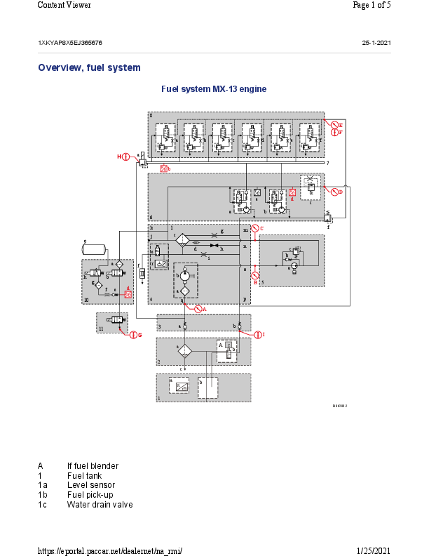
PACCAR MX-13 Engine Fuel System Overview
This document provides a comprehensive overview of the fuel system for the PACCAR MX-13 engine, detailing its components, functions, and measurement points.
System Components
The MX-13 engine fuel system comprises numerous interconnected components designed for efficient fuel delivery and management. Key components include:
- Fuel Tank (1): Stores the fuel.
- Fuel lift pump (4): Draws fuel from the tank and supplies it at low pressure.
- Fuel filtration module (5): Includes a sieve (4a), filter and water separator element (4c, 5b), activated carbon canister (4f), and water drain valve (4e).
- Engine-chassis fuel interface (3): Connects the engine fuel system to the chassis.
- Common rail (7): A high-pressure accumulator for fuel distribution to injectors.
- Common rail pump units (6a, 6b): High-pressure pumps that supply fuel to the common rail.
- Injectors (8): Deliver fuel into the combustion chambers.
- Fuel intake module (9, 10): Manages fuel intake and potentially dosing.
- Sensors: Fuel pressure sensors (6d, 7b), Fuel temperature sensor (6e), Water in fuel sensor (5d).
- Valves: Shutoff valves (3a, 3b, 3c, 9d), pressure control valves (6c, 6g), pressure release valves (5c, 7a), injector back leak valves (6f, 6h), fuel blend valve (2b), air shutoff valve (9b).
- Other components: Chassis filter (2), hand priming pump (4b), air supply (9a).
Fuel System Diagram Description
The fuel system diagram illustrates the flow of fuel through various stages. The primary flow paths are indicated by color-coded lines:
Flow A (Suction): Fuel is drawn from the Fuel Tank (1) via stand pipes (1a) and supplied to the Fuel lift pump (4). This path includes the hand priming pump (4b).
Flow B (Low Pressure): After the Fuel lift pump (4), fuel passes through the Chassis filter (2), Fuel filtration module (5) (containing a sieve, filter/water separator, activated carbon canister), and reaches the Low-pressure fuel gallery (6). This section also includes the water in fuel sensor/drain valve (5d) and connects to the Engine-chassis fuel interface (3).
Flow C (Boost Pressure): Fuel is pressurized by the Common rail pump units (6a, 6b) located in the engine block (6) and delivered to the Common rail (7). This is the high-pressure fuel supply.
Flow D (Injector Return): Fuel that leaks past the injectors (8) or is returned from the common rail system flows back through injector back leak passages (8a) and return lines (8b), often via the Common rail (7) and other return paths.
Flow E (Return): Excess fuel from components like the Common rail pressure release valve (7a) is returned, typically to the fuel tank.
The diagram also shows the Fuel dosing module (10) and the Air supply system (9) with its associated valves and sensors.
Fuel System Measuring Points
The following table outlines key measuring points within the fuel system, along with their descriptions and additional information for diagnostics:
| Measuring Point | Description | Additional Information |
|---|---|---|
| A | Pressure before the manual fuel lift pump (suction side) (P4) | See job (Check fuel system low pressure) |
| B | Pressure after the manual fuel lift pump (suction side) (P2) | See job (Check fuel system low pressure) |
| C | Pressure after fuel lift pump (pressure side) (P3) | |
| D | Pressure return pipe to fuel tank (P5) | |
| E | Pressure injector leak (P6) | |
| F | Injector leak flow | DAVIE4 test 'Evaluate the injector back leak' in DAVIE4 in combination with job (Check fuel system high pressure) |
| G | Fuel dosing module delivery | See job (Checking fuel delivery dosing module, fuel) |
| Fuel dosing module leakage | See job (Checking leakage dosing module, fuel) | |
| H | Common rail pressure release valve leakage | DAVIE4 test 'Evaluate the injector back leak' in DAVIE4 in combination with job (Check fuel system high pressure) |
| I | Fuel flow in fuel tank return pipe | See job (Check fuel flow fuel tank return pipe) |
| 6d | Fuel pressure in gallery from PCI ECU (D420) (P1) | Fuel pressure (Relative) in the DAVIE PCI application. For specifications, see technical data of job (Check fuel system low pressure) |
| 7b | Common rail pressure from PCI ECU (D420) | Rail pressure in the DAVIE PCI application |
| 10d | Fuel intake module - fuel pressure from EAS-3 ECU (D374) | Intake module fuel pressure in the DAVIE EAS-3 application |
