jfet-2n4391-2n4392-2n4393-interfet.r00
File info: application/pdf · 6 pages · 346.44KB
jfet-2n4391-2n4392-2n4393-interfet.r00
Full PDF Document

If the inline viewer fails, it will open the original document in compatibility mode automatically. You can also open the file directly.
Extracted Text
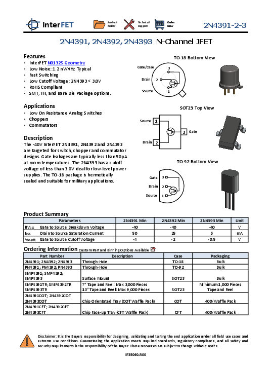
InterFET

Product Folder

Technical Support

Order Now

2N4391-2-3

2N4391, 2N4392, 2N4393 N-Channel JFET

Features
� InterFET N0132S Geometry � Low Noise: 1.2 nV/Hz Typical � Fast Switching � Low Cutoff Voltage: 2N4393 < 3.0V � RoHS Compliant � SMT, TH, and Bare Die Package options.
Applications
� Low On Resistance Analog Switches � Choppers � Commutators
Description
The -40V InterFET 2N4391, 2N4392 and 2N4393 are targeted for switch, chopper and commutator designs. Gate leakages are typically less than 50pA at room temperatures. The 2N4393 has a cutoff voltage of less than 3.0V ideal for low-level power supplies. The TO-18 package is hermetically sealed and suitable for military applications.

Gate/Case Drain 2 Source

TO-18 Bottom View
3
1

Source 1 Drain 2

SOT23 Top View 3 Gate

Gate 3 Drain 2 Source 1

TO-92 Bottom View

Product Summary
Parameters BVGSS Gate to Source Breakdown Voltage IDSS Drain to Source Saturation Current VGS(off) Gate to Source Cutoff Voltage

2N4391 Min -40 50 -4

Ordering Information Custom Part and Binning Options Available

Part Number

Description

2N4391; 2N4392; 2N4393 Through-Hole

PN4391; PN4392; PN4393 Through-Hole

SMP4391; SMP4392;

SMP4393

Surface Mount

SMP4391TR; SMP4392TR 7" Tape and Reel: Max 3,000 Pieces

SMP4393TR

13" Tape and Reel: Max 9,000 Pieces

2N4391COT; 2N4392COT

2N4393COT

Chip Orientated Tray (COT Waffle Pack)

2N4391CFT; 2N4392CFT

2N4393CFT

Chip Face-up Tray (CFT Waffle Pack)

2N4392 Min -40 25 -2
Case TO-18 TO-92
SOT23
SOT23
COT
CFT

2N4393 Min

Unit

-40

V

5

mA

-0.5

V

Packaging Bulk Bulk
Bulk Minimum 1,000 Pieces
Tape and Reel
400/Waffle Pack
400/Waffle Pack

Disclaimer: It is the Buyers responsibility for designing, validating and testing the end application under all field use cases and extreme use conditions. Guaranteeing the application meets required standards, regulatory compliance, and all safety and security requirements is the responsibility of the Buyer. These resources are subject to change without notice.
IF35060.R00

InterFET

Product Folder

Technical Support

Order Now

2N4391-2-3

Electrical Characteristics

Maximum Ratings (@ TA = 25�C, Unless otherwise specified)
Parameters VRGS Reverse Gate Source and Gate Drain Voltage IFG Continuous Forward Gate Current PD Continuous Device Power Dissipation P Power Derating TJ Operating Junction Temperature TSTG Storage Temperature

Value -40 50 1800 12
-55 to 125 -65 to 150

Unit V mA
mW mW/�C
�C �C

Static Characteristics (@ TA = 25�C, Unless otherwise specified)

V(BR)GSS IGSS VGS(OFF) VGS(F) IDSS

Parameters Gate to Source Breakdown Voltage Gate to Source Reverse Current Gate to Source Cutoff Voltage Gate to Source Forward Voltage Drain to Source Saturation Current

ID(OFF) Drain Cutoff Current

VDS(ON) RDS(ON)

Drain to Source ON Voltage
Static Drain to Source ON Resistance

Conditions
VDS = 0V, IG = -1A
VDS = -20V, VGS = 0V, TA = 25�C VDS = -20V, VGS = 0V, TA = 150�C
VDS = 20V, ID = 1nA
VDS = 0V, IG = 1mA
VGS = 0V, VDS = 20V (Pulsed)
VDS = 20V, VGS = -5V, TA = 25�C VDS = 20V, VGS = -5V, TA = 150�C VDS = 20V, VGS = -7V, TA = 25�C VDS = 20V, VGS = -7V, TA = 150�C VDS = 20V, VGS = -12V, TA = 25�C VDS = 20V, VGS = -12V, TA = 150�C
VGS = 0V, ID = 3mA VGS = 0V, ID = 6mA VGS = 0V, ID = 12mA
VGS = 0V, ID = 1mA

2N4391 Min Max -40
-100 -200 -4 -10
1 50 150
100 200
0.4 30

2N4392 Min Max -40
-100 -200 -2 -5
1 25 75
100 200
0.4
60

2N4393 Min Max Unit

-40

V

-100 pA -200 nA

-0.5 -3 V

1V

5 30 mA
100 pA 200 nA
pA nA pA nA 0.4 V

100

Dynamic Characteristics (@ TA = 25�C, Unless otherwise specified)

RDS(ON) Ciss

Parameters Drain to Source ON Resistance
Input Capacitance

Crss

Reverse Transfer Capacitance

td tr tD(OFF) tf

Turn-On Delay Time Rise Time Turn-Off Delay Time Fall Time

Conditions
VGS = 0V, ID = 0A, f = 1kHz
VDS = 20V, VGS = 0V, f = 1MHz VDS = 0V, VGS = -5V, f = 1MHz VDS = 0V, VGS = -7V, f = 1MHz VDS = 0V, VGS = -12V, f = 1MHz
VDD = 10V, VGS(ON) = 0V VDD = 10V, VGS(ON) = 0V VDD = 10V,VGS(ON) = 0V VDD = 10V,VGS(ON) = 0V

2N4391 Min Max
30 14
3.5 15 5 20 15

2N4392 Min Max
60 14
3.5
15 5 35 20

2N4393 Min Max Unit
100
14 pF 3.5
pF
15 ns 5 ns 50 ns 30 ns

2N4391-2-3
Document Number: IF35060.R00

2 of 5
www.InterFET.com

InterFET Corporation
December, 2018

InterFET

Product Folder

Technical Support

Order Now

SOT23 (TO-236AB) Mechanical and Layout Data

Package Outline Data

2N4391-2-3

Suggested Pad Layout

1. All linear dimensions are in millimeters. 2. Package weight approximately 0.12 grams 3. Molded plastic case UL 94V-0 rated 4. For Tape and Reel specifications refer to
InterFET CTC-021 Tape and Reel Specification, Document number: IF39002 5. Bulk product is shipped in standard ESD shipping material 6. Refer to JEDEC standards for additional information.

2N4391-2-3
Document Number: IF35060.R00

1. All linear dimensions are in millimeters. 2. The suggested land pattern dimensions have been
provided for reference only. A more robust pattern may be desired for wave soldering.

3 of 5
www.InterFET.com

InterFET Corporation
December, 2018

InterFET

Product Folder

Technical Support

Order Now

TO-18 Mechanical and Layout Data

Package Outline Data

2N4391-2-3

Suggested Through-Hole Layout

1. All linear dimensions are in millimeters. 2. Package weight approximately 0.29 grams 3. Bulk product is shipped in standard ESD shipping
material 4. Refer to JEDEC standards for additional
information.
1. All linear dimensions are in millimeters. 2. The suggested land pattern dimensions have been
provided as a straight lead reference only. A more robust pattern may be desired for wave soldering and/or bent lead configurations.

2N4391-2-3
Document Number: IF35060.R00

4 of 5
www.InterFET.com

InterFET Corporation
December, 2018

InterFET

Product Folder

Technical Support

Order Now

TO-92 Mechanical and Layout Data

Package Outline Data

2N4391-2-3

Suggested Through-Hole Layout

1. All linear dimensions are in millimeters. 2. Package weight approximately 0.19 grams 3. Molded plastic case UL 94V-0 rated 4. Bulk product is shipped in standard ESD shipping
material 5. Refer to JEDEC standards for additional
information.

2N4391-2-3
Document Number: IF35060.R00

1. All linear dimensions are in millimeters. 2. The suggested land pattern dimensions have been
provided as a straight lead reference only. A more robust pattern may be desired for wave soldering and/or bent lead configurations.

5 of 5
www.InterFET.com

InterFET Corporation
December, 2018

Mouser Electronics
Authorized Distributor
Click to View Pricing, Inventory, Delivery & Lifecycle Information:
InterFET:
2N4393 SMP4392 SMP4393 SMP4391 2N4392 2N4391