MAX77960/MAX77961 Evaluation Kit - Evaluates: MAX77960/MAX77961
File info: application/pdf · 17 pages · 3.37MB
MAX77960/MAX77961 Evaluation Kit - Evaluates: MAX77960/MAX77961
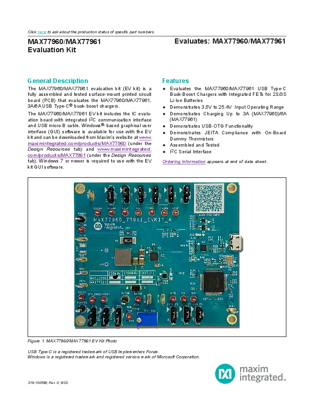
The MAX77960/MAX77961 evaluation kit (EV kit) is a fully assembled and tested surface-mount printed circuit board (PCB) that evaluates the MAX77960/MAX77961, 3A/6A USB Type-C buck-boost chargers.
MAX77960/MAX77961 Evaluation Kit - Evaluates: MAX77960 ...
clicking on the icon in the Windows Start menu. 4) Make jumper connections based on the Position column in Table 1. Change it later when evaluating more features. If evaluation is with a 3-cell Li-ion battery or equival…
Full PDF Document

If the inline viewer fails, it will open the original document in compatibility mode automatically. You can also open the file directly.
Extracted Text
Click here to ask about the production status of specific part numbers.
MAX77960/MAX77961 Evaluation Kit

Evaluates: MAX77960/MAX77961

General Description
The MAX77960/MAX77961 evaluation kit (EV kit) is a fully assembled and tested surface-mount printed circuit board (PCB) that evaluates the MAX77960/MAX77961, 3A/6A USB Type-C� buck-boost chargers.
The MAX77960/MAX77961 EV kit includes the IC evaluation board with integrated I2C communication interface and USB micro-B cable. Windows�-based graphical user interface (GUI) software is available for use with the EV kit and can be downloaded from Maxim's website at www. maximintegrated.com/products/MAX77960 (under the Design Resources tab) and www.maximintegrated. com/products/MAX77961 (under the Design Resources tab). Windows 7 or newer is required to use with the EV kit GUI software.

Features
 Evaluates the MAX77960/MAX77961 USB Type-C Buck-Boost Chargers with Integrated FETs for 2S/3S Li-Ion Batteries
 Demonstrates 3.5V to 25.4V Input Operating Range  Demonstrates Charging Up to 3A (MAX77960)/6A
(MAX77961)  Demonstrates USB-OTG Functionality  Demonstrates JEITA Compliance with On-Board
Dummy Thermistors  Assembled and Tested  I2C Serial Interface
Ordering Information appears at end of data sheet.

Figure 1. MAX77960/MAX77961 EV Kit Photo USB Type-C is a registered trademark of USB Implementers Forum. Windows is a registered trademark and registered service mark of Microsoft Corporation.
319-100599; Rev 0; 9/20

MAX77960/MAX77961 Evaluation Kit

Evaluates: MAX77960/MAX77961

MAX77960/MAX77961 EV Kit Files

FILE MAX77960_MAX77961GUISetupX.X.X.exe

DESCRIPTION
Installs all EV kit files on PC

MAX77960/MAX77961 EV Kit Component List

PART

QTY

DESCRIPTION

MAX77960/MAX77961EVKIT

1

MAX77960/MAX77961 evaluation kit

USB high-speed A-to-B cable 1 USB Micro-B cable

Quick Start
Required Equipment
 MAX77960/MAX77961 EV kit  Adjustable DC power supply  Battery or simulated battery
� 2- or 3-cell Li-ion protected battery � Simulated battery or preloaded power supply  Oscilloscope  Two voltmeters  Two ammeters  Lab cables with appropriate current rating  USB Micro-B cable  PC with Windows 7 or newer operating system and USB port

Setup Overview
A typical bench setup for the MAX77960/MAX77961 EV Kit is shown in Figure 2.
Procedure
The EV kit is fully assembled and tested. Follow the steps below to install the EV kit software, make required hardware connections, and start operation of the kit. The EV kit software can be run without hardware attached. Note that after communication is established the IC must still be configured correctly for desired operation mode. Make sure the PC is connected to the internet throughout the process so that the USB driver can be automatically installed.
Note: Do not turn on the DC power supply until all connections are made.
1) Visit www.maximintegrated.com/products/MAX77960 or www.maximintegrated.com/products/MAX77961 under the Design Resources tab to download the latest version of the MAX77960/MAX77961 EV kit GUI software. Save the software to a temporary folder and unpack the zip file.
2) Install the EV kit software on your computer by running the MAX77960_MAX77961GUISetupX.X.X.exe program inside the temporary folder. The program files are copied, and icons are created in the Windows Start menu. The software requires the .NET Framework 4.5 or later. If you are connected to the Internet, Windows automatically updates the .NET framework as needed.

BENCH VOLTMETER
DC POWER SUPPLY
PC

CHGINS

PGNDS

MAX77960/MAX77961 BATTP

A

DCIN

EV KIT

BATTN

GND BATSP

MAXUSB (USB INTERFACE)

BATSN

Figure 2. EV Kit Simple Block Diagram

A

2S/3S LI-ION

BATTERY OR

SIMULATED

BATTERY

BENCH VOLTMETER

www.maximintegrated.com

Maxim Integrated  2

MAX77960/MAX77961 Evaluation Kit

Evaluates: MAX77960/MAX77961

3) The EV kit software launches automatically after installation, or alternatively, it can be launched by clicking on the icon in the Windows Start menu.
4) Make jumper connections based on the Default Position column in Table 1. Change it later when evaluating more features. If evaluation is with a 3-cell Li-ion battery or equivalent simulated battery, place J8 in 2-3 position so that the MAX77960/MAX77961 are configured for 3-cell.

5) Use the USB cable provided with the EV kit to connect the EV kit to the PC's USB port.
6) Connect a 2- or 3-cell Li-ion battery or simulated battery to the connectors labeled BATTP and BATTN.
7) Connect a DC power supply to the connectors labeled DCIN and GND.
8) Launch the MAX77960/MAX77961 GUI software.
9) Select Device > Connect from the window options to connect to the EV kit.

Table 1. Jumper Connection Guide

JUMPER NUMBER
J2 J3 J4 J5 J6 J7

PCB SILKSCREEN
SCL SDA INTB OTG_EN DISQBAT STBY

DEFAULT POSITION
1-2 1-2 1-2 2-3 2-3 2-3

FUNCTION
1-2: Connects SCL with the on-board MAXUSB (USB-to-I2C interface) to allow communication with the GUI software. 2-3: Disconnects SCL from the on-board MAXUSB.
1-2: Connects SDA with the on-board MAXUSB to allow communication with the GUI software. 2-3: Disconnects SDA from the on-board MAXUSB.
1-2: Connects INTB with the on-board MAXUSB to allow communication with the GUI software. 2-3: Disconnects INTB from the on-board MAXUSB.
1-2: Connects OTG_EN to PVL. OTG function is enabled. 2-3: Connects OTG_EN to GND. OTG function enable is controlled by MODE[3:0] bitfield.
1-2: Connects DISQBAT to PVL. QBAT FET is disabled. 2-3: Connects DISQBAT to GND. QBAT FET is controlled by the DISIBS bit and power-path state machine/internal logic control.
1-2: Connects STBY to PVL. DC-DC is disabled. 2-3: Connects STBY to GND. DC-DC is controlled by STBY_EN bit and power-path state machine/internal logic control.

1-2: Connects CNFG to PVL. Number of serially connected battery cells is

J8

CNFG

1-2

configured as 2S. 2-3: Connects CNFG to R5. Number of serially connected battery cells is

configured as 3S.

1-2: Connects VSET to PVL. Default charge termination voltage is

J9

VSET

1-2

same as decode of reset value of CHG_CV_PRM[5:0]. 2-3: Connects VSET to R49. Default charge termination voltage is

programmed by R49.

www.maximintegrated.com

Maxim Integrated  3

MAX77960/MAX77961 Evaluation Kit

Evaluates: MAX77960/MAX77961

Table 1. Jumper Connection Guide (continued)

JUMPER NUMBER
J10

PCB SILKSCREEN
INLIM

DEFAULT POSITION
1-2

FUNCTION
1-2: Connects INLIM to PVL. Default input current limit is same as decode of reset value of CHGIN_ILIM[6:0]. 2-3: Connects INLIM to R51. Default input current limit is programmed by R51.

1-2: Connects ITO to PVL. Default top-off charge current is same as

J11

ITO

1-2

decode of reset value of TO_ITH[2:0]. 2-3: Connects ITO to R52. Default top-off charge current is programmed by

R52.

1-2: Connects ISET to PVL. Default fast-charge current is same as decode

J12

ISET

1-2

of reset value CHGCC[5:0]. 2-3: Connects ISET to R53. Default fast-charge current is programmed by

R53.

1-2: Connects THM to potentiometer R39. Adjust resistance of R39 to

J13

THM

2-3

emulate resistance change of a 10k thermistor at different temperature. 2-3: Connects THM to a fixed 10k resistor. This emulates resistance of a

10k thermistor at 25�C.

Detailed Description of Software
The MAX77960/MAX77961 GUI software provides an easyto-use interface to control the function blocks of the IC.
Software Installation
Double-click the MAX77960_MAX77961GUISetupX.X.X.exe icon to begin the installation process. Follow the prompts to complete the installation. The evaluation software can be uninstalled in the Add/Remove Programs tool in the Control Panel. After the installation is complete, open the Maxim Integrated/MAX77960_ MAX77961 folder and run MAX77960_MAX77961.exe or select it from the program menu. Figure 3 shows a splash screen containing information about the evaluation kit that appears while the program is loading.
Establish Communication
Power up the MAX77960/MAX77961 by connecting a 2- or 3-cell Li-ion battery or simulated battery at BATTP/ BATTN. Open the GUI software and select Device > Connect. A window should pop up showing that a slave address 0xD2 has been found. If not, check the USB connection and power. Choose Read and Close and the status bar displays "Connected" to signify active communication. An example of a successful connection is shown in Figure 4.

Figure 3. EV Kit Splash Screen

www.maximintegrated.com

Maxim Integrated  4

MAX77960/MAX77961 Evaluation Kit

Evaluates: MAX77960/MAX77961

Main Display
Status bits and programmable functions of the charger can be accessed through the interface tabs in the left column of the window (Figure 5).

Figure 4. MAX77960/MAX77961 Communication Window

Figure 5. MAX77960/MAX77961 Top-Level Registers www.maximintegrated.com

Maxim Integrated  5

MAX77960/MAX77961 Evaluation Kit

Evaluates: MAX77960/MAX77961

Register Write Access
Modification of the charger registers are locked by default to prevent arbitrary changes. Therefore, changes made to the charger registers in the locked state are not applied to the EV kit. To unlock register writing, select the 0x3 = Unlocked option in the Charger Settings Protection dropdown menu from the Charger Configurations 6 register in the Configuration 4-7 tab, and then click Write (Figure 6). Read the register and the Charger Settings Protection setting should remain in the 0x3 = Unlocked state to signify open register access.
From this point onwards, modifications written to any of the registers apply to the EV kit. For example, the CHGIN Input Current Limit can be changed in the Charger Configurations 8 register by selecting the required value and clicking Write (Figure 7), but only after the registers have been unlocked.

Detailed Description of Hardware
Battery Charger Test Setup
1) Connect a 2- or 3-cell Li-Ion battery or simulated battery between BATTP and BATTN.
2) Adjust voltage and current limits of the DC power supply to 5.0V and 3.0A. Output of the power supply is off.
3) Connect the power supply between DCIN and GND on the EV kit board.
4) Open the EV kit GUI and connect to the EV kit.
5) In the Configuration 4-7 tab, set Charger Settings Protection in the Charger Configurations 6 register to 0x3 = Unlocked. Click Write to send the command to the charger.

Figure 6. Charger Register Write Access www.maximintegrated.com

Maxim Integrated  6

MAX77960/MAX77961 Evaluation Kit

Evaluates: MAX77960/MAX77961

6) Program the appropriate charger settings for your system. In the Configuration 8-10 tab, set CHGIN Input Current Limit in the Charger Configurations 8 register. Press Write to send the command to the charger. Note that the maximum setting of CHGIN Input Current Limit for the MAX77960 is 0x40 = 3150mA.
7) In the Configuration 0-3 tab, set Fast Charge Current in the Charger Configurations 2 register. Press Write to send the command to the charger. Note that the maximum setting of Fast Charge Current for the

MAX77960 is 0x21 = 3000mA.
8) In the Charger Configuration 0 register of the Configuration 0-3 tab, set Smart Power Selector to 0x5 = Charger = On, OTG = Off, and DCDC = On and click Write to enable charger mode.
9) Turn on the DC power supply's output to enable charging.
10) Use data log equipment to log the charge current and battery voltage profile while charging a 2- or 3-cell Li-ion battery.

Figure 7. Change CHGIN Input Current Limit after Unlocking Charger Settings Protection

www.maximintegrated.com

Maxim Integrated  7

MAX77960/MAX77961 Evaluation Kit

Evaluates: MAX77960/MAX77961

Component Suppliers

SUPPLIER MURATA SAMTEC SULLINS ELECTRONICS CORP TAIYO-YUDEN TDK VISHAY COILCRAFT PANASONIC FUTURE TECHNOLOGY DEVICES INTL LTD

PHONE 770-436-1300 800-726-8329 760-774-0125 603-669-7587 847-803-6100 408-970-5852 847-639-6400 800-344-2112 503-547-0988

WEBSITE www.murata-northamerica.com www.samtec.com www.sullinselectronics.com www.t-yuden.com www.tdk.com www.vishay.com www.coilcraft.com https://na.industrial.panasonic.com www.ftdichip.com

Note: Indicate that you are using the MAX77960/MAX77961 when contacting these component suppliers.

Ordering Information
PART MAX77960EVKIT-06# MAX77961EVKIT-06# #Denotes RoHS compliant.

TYPE EV Kit EV Kit

www.maximintegrated.com

Maxim Integrated  8

MAX77960/MAX77961 Evaluation Kit

Evaluates: MAX77960/MAX77961

MAX77960_06 EV Kit Bill of Materials

REF_DES

QTY

MFG PART #

AVL, BATSP, CHGINS,

CSINN, CSINP, DISQBAT,

INOKB, INTB, OTG_EN,

16

PVL, SCL, SDA, STAT, STBY,

THM, VSYSS

5000

BATTN, BATTP, DCIN, GND, GND1-GND3, VSYS

8

BATSN, PGND1S, PGNDS

3

C1, C15, C18-C21, C23-C29, C35

14

C2, C3, C12, C13, C22

5

C4

1

C5

1

C6

1

C7, C8

2

C9, C10

2

C11, C14

2

C16, C17, C30-C32

5

C34, C36

2

C42

1

D1

1

9020 BUSS
5011
GRM155R71A104JA01
GRM155R61A475MEAA GRM32ER7YA106KA12 GRM155C81E105KE11
TMK212BBJ106KG-T GRM155R71C224KA12
TMK325ABJ476MM GRM1555C1H270JA01
C0402C105K8PAC GRM155R71H153KA12
GRM155R71E473K PMEG4050EP

DS2

1

LTST-C190CKT

DS3

1

LTST-C190KFK

J1

1

10118193-0001LF

J2-J13

12

PEC03SAAN

L1

1

PA5007.332NLT

L2-L4

3

BLM18AG601SN1

Q1

1

R1, R7, R14-R16, R18, R22,

R24, R26, R32,

14

R43, R44, R46, R47

DMN3016LFDE ERJ-2GE0R00

DESCRIPTION
RED MINI TESTPOINTS
WIRE, BUSS 20G PLATED SOLID COPPER
BLACK BIG TESTPOINTS
CAP+, 0.1�F, 10%, 6.3V, X5R, 0402
CAP+, 4.7�F, 20%, 10V, X5R, 0402 CAP+, 10�F, 10%, 35V, X7R, 1210 CAP+, 1�F, 10%,25V, X6S, 0402 CAP+, 10�F, 10%, 25V, X5R, 0805 CAP+, 0.22�F, 10%,16V, X7R, 0402 CAP+, 47�F, 20%, 25V, X5R,1210 CAP+, 27pF, 5%, 50V, COG, 0402 CAP+, 1�F, 10%, 10V, X5R, 0402 CAP+, 0.015�F, 20%, 50V, X7R, 0402 CAP+, 0.047�F, 10%, 25V, X7R, 0402 DIODE+, SCH, 40V, 5A, SOD-128 LED+, SURFACE MOUNT, RED OSLON 2.2V, 350mA, 3X3MM LED+, SURFACE MOUNT, ORANGE RCPT+, MICRO B USB 2.0,5 POS HEADER+, 3POS,. 100", SNGL, TIN R/A, TH INDUCTOR+, 3.3�H, 20%, 10A FERRITE-BEAD, 600nH, 0.5A, 0603 �H, 20%, 5.8A, 4.1 x 4.1MM TRAN, NCH, 10A, 30V
RES+, 0, 0%, 0402

www.maximintegrated.com

Maxim Integrated  9

MAX77960/MAX77961 Evaluation Kit

Evaluates: MAX77960/MAX77961

MAX77960_06 EV Kit Bill of Materials (continued)

REF_DES R2
R4, R36 R5 R6 R8
R9, R13 R10
R11, R23 R12, R54
R17 R19, R31, R41, R45
R20, R21 R27, R28
R29 R30 R35 R37 R38, R42 R39 R48 U1 U2 U4 U5, U6 Y1 C33, C37, C38, C40, C41 R25 R3, R40, R49, R51-R53

QTY 1 2 1 1 1 2 1 2 2 1 4 2 2 1 1 1 1 2 1 1 1 1 1 2 1 5 1 6

MFG PART # CRA2512-FZ-R010ELF
CRCW0402200KFK CRCW04028K66FK CRCW04024R70FK CRCW040212K0FK CRCW040227R0FK CRCW04021M00FK CRCW04021K00FK CRCW040210K0FK CRCW04024752FK CRCW0402100KFK CRCW04024752FK CRCW04024K70FK
ERJ-2GEJ474 CRCW0402169KFK CRCW0402470RFK
ERJ-2RKF2203 CRCW04022K20FK
3296Y-1-503LF ERJ-2GEJ132
MAX77960 FT2232HL MAX14611 MAX8512 7M-12.000MAAJ
OPEN OPEN OPEN

DESCRIPTION RES+, 0.01, 1%, 3W, 2512 RES+, 200K, 1%, 0402 RES+, 8.66K, 1%, 0402 RES+, 4.7, 1%, 0402 RES+, 12K, 1%, 0402 RES+, 27, 1%, 0402 RES+, 1M, 1%, 0402 RES+, 1K, 1%, 0402 RES+, 10K, 1%, 0402 RES+, 47.5K, 1%, 0402 RES+, 100K, 1%, 0402 RES+, 10, 1%, 0402 RES+, 4.7K, 1%, 0402 RES+, 470K, 5%, 0402 RES+, 169K, 1%, 0402 RES+, 470, 1%, 0402 RES+, 220K, 1%, 0402 RES+, 2.2K, 1%, 0402 RES+, POT, 50K RES+, 1.3K, 5%, 0402 MAX77960EFV06+ FT2232HL MAX14611ETD+ MAX8512EXK+ CRYSTAL+, SMT,12MHz, +/-30PPM N/A RES+, 0, 0%, 0805 N/A

www.maximintegrated.com

Maxim Integrated  10

MAX77960/MAX77961 Evaluation Kit

Evaluates: MAX77960/MAX77961

MAX77961_06 EV Kit Bill of Materials

REF_DES
AVL, BATSP, CHGINS, CSINN, CSINP, DISQBAT, INOKB, INTB, OTG_EN, PVL, SCL, SDA, STAT, STBY,
THM, VSYSS

QTY 16

MFG PART # 5000

BATTN, BATTP, DCIN, GND, GND1-GND3, VSYS
BATSN, PGND1S, PGNDS C1, C15, C18-C21, C23-C29, C35
C2, C3, C12, C13, C22 C4 C5 C6
C7, C8 C9, C10 C11, C14 C16, C17, C30-C32 C34, C36
C42 D1

8

9020 BUSS

3

5011

14

GRM155R71A104JA01

5

GRM155R61A475MEAA

1

GRM32ER7YA106KA12

1

GRM155C81E105KE11

1

TMK212BBJ106KG-T

2

GRM155R71C224KA12

2

TMK325ABJ476MM

2

GRM1555C1H270JA01

5

C0402C105K8PAC

2

GRM155R71H153KA12

1

GRM155R71E473K

1

PMEG4050EP

DS2

1

LTST-C190CKT

DS3 J1 J2-J13 L1

1

LTST-C190KFK

1

10118193-0001LF

12

PEC03SAAN

1

PA5007.332NLT

L2-L4

3

BLM18AG601SN1

Q1
R1, R7, R14-R16, R18, R22, R24, R26, R32, R43,
R44, R46, R47 R2
R4, R36 R5 R6 R8

1

DMN3016LFDE

14

ERJ-2GE0R00

1

CRA2512-FZ-R010ELF

2

CRCW0402200KFK

1

CRCW04028K66FK

1

CRCW04024R70FK

1

CRCW040212K0FK

DESCRIPTION
RED MINI TESTPOINTS
WIRE, BUSS 20G PLATED SOLID COPPER
BLACK BIG TESTPOINTS
CAP+, 0.1�F, 10%, 6.3V, X5R, 0402
CAP+, 4.7�F, 20%, 10V, X5R, 0402 CAP+, 10�F, 10%, 35V, X7R, 1210 CAP+, 1�F, 10%, 25V, X6S, 0402 CAP+, 10�F, 10%, 25V, X5R, 0805 CAP+, 0.22�F, 10%, 16V, X7R, 0402 CAP+, 47�F, 20%, 25V, X5R,1210 CAP+, 27pF, 5%, 50V, COG, 0402 CAP+, 1�F, 10%, 10V, X5R, 0402 CAP+, 0.015�F, 20%, 50V, X7R, 0402 CAP+, 0.047�F, 10%, 25V, X7R, 0402 DIODE+, SCH,40V,5A, SOD-128 LED+, SURFACE MOUNT, RED OSLON 2.2V, 350mA, 3X3MM LED+, SURFACE MOUNT, ORANGE RCPT+, MICRO B USB 2.0, 5 POS HEADER+, 3 POS,. 100", SNGL, TIN R/A, TH INDUCTOR+, 3.3�H, 20%, 10A FERRITE-BEAD, 600nH, 0.5A, 0603 �H, 20%, 5.8A, 4.1 x 4.1MM TRAN, NCH,10A, 30V
RES+, 0,0%,0402
RES+, 0.01, 1%, 3W, 2512 RES+, 200K, 1%, 0402 RES+, 8.66K, 1%, 0402 RES+, 4.7, 1%, 0402 RES+, 12K, 1%, 0402

www.maximintegrated.com

Maxim Integrated  11

MAX77960/MAX77961 Evaluation Kit

Evaluates: MAX77960/MAX77961

MAX77961_06 EV Kit Bill of Materials (continued)

REF_DES R9, R13
R10 R11, R23 R12, R54
R17 R19, R31, R41, R45
R20, R21 R27, R28
R29 R30 R35 R37 R38, R42 R39 R48 U1 U2 U4 U5, U6 Y1 C33, C37, C38, C40, C41 R25 R3, R40, R49, R51-R53

QTY 2 1 2 2 1 4 2 2 1 1 1 1 2 1 1 1 1 1 2 1
5
1
6

MFG PART # CRCW040227R0FK CRCW04021M00FK CRCW04021K00FK CRCW040210K0FK CRCW04024752FK CRCW0402100KFK CRCW04024752FK CRCW04024K70FK ERJ-2GEJ474 CRCW0402169KFK CRCW0402470RFK ERJ-2RKF2203 CRCW04022K20FK 3296Y-1-503LF ERJ-2GEJ132 MAX77961 FT2232HL MAX14611 MAX8512 7M-12.000MAAJ
OPEN
OPEN
OPEN

DESCRIPTION RES+, 27, 1%, 0402 RES+, 1M, 1%, 0402 RES+, 1K, 1%, 0402 RES+, 10K, 1%, 0402 RES+, 47.5K, 1%, 0402 RES+, 100K, 1%, 0402 RES+, 10, 1%, 0402 RES+, 4.7K, 1%, 0402 RES+, 470K, 5%, 0402 RES+, 169K, 1%, 0402 RES+, 470, 1%, 0402 RES+, 220K, 1%, 0402 RES+, 2.2K, 1%, 0402 RES+, POT, 50K RES+, 1.3K, 5%, 0402 MAX77961EFV06+ FT2232HL MAX14611ETD+ MAX8512EXK+ CRYSTAL+, SMT,12MHz, �30PPM
N/A
RES+, 0, 0%, 0805
N/A

www.maximintegrated.com

Maxim Integrated  12

Maxim Integrated  13

www.maximintegrated.com

DCIN GND

DCIN

C33

OPEN

N/A

R20

10

3W R2
0.01 2512RES
10V C35 0.1UF

0402

J2

1 SCL_FT

2

SCL

3

PEC03SAAN

J3 1 SDA_FT 2 SDA
3
PEC03SAAN

50V C34 0.015UF 0402
PVL
R4 200K

J4

1 INTB_FT 2 INTB
3

INOKB

PEC03SAAN

STAT

C37

C38

OPEN

OPEN

R21

1210

1210

10

50V C36
0.015UF
0402

CSINN CSINP
AVL
PVL

R36 200K

SCL SDA INTB

OTG_EN DISQBAT
STBY GND2
GND3

PVL J5
1 2 3
PEC03SAAN

J6
1 2 3
PEC03SAAN

CHGIN
35V C4 10UF 1210

CHGINS PGNDS

CSINN

U1 MAX77960 2 CHGIN
30 CSINN

BST1 1 BST1 LX1 3 LX1
LX2 5 LX2 BST2 9 BST2

C8 0.22UF 0402
C7 0.22UF
0402

LX1

L1

2

1

3.3UH
PA5007.332NLT

LX2

EVKIT PART NUMBER MAX77960EVKIT-06# MAX77961EVKIT-06#

CSINP

29 CSINP

AVL
R6 4.7
PVL

10V C2 4.7UF
0402
10V C3
4.7UF 0402

26 AVL 27 PVL

SCL

14 SCL

SDA

15 SDA

INTB

18 INTB

INOKB

17 INOKB

STAT

16 STAT

OTG_EN DISQBAT STBY

7 OTGEN 8 DISQBAT 28 STBY

J7
1 2 3
PEC03SAAN

SYS 6 SYS SYSA 19SYS
PGND 4

C5 1UF 25V 0402

VSYSS PGND1S

C9 47UF 1210 25V

C10 47UF 1210 25V

C40 OPEN 1210

C41 OPEN 1210

BATT 12BATT

C6 10UF
0805 25V

THM 13THM BATSP 11BATSP
GND 20

BATSN 10BATSN

ISET 23ISET

ITO 25ITO

INLIM 21INLIM

VSET 24VSET

CNFG 22CNFG

J8

1

2

3

PEC03SAAN

R5 8.66K

THM

AVL
R12 10K

BATSP

R24

0 GND1

BATSN R26
0

R40 BATTN
OPEN

J9
1 2 3
PEC03SAAN
R49 OPEN

J10
1 2 3

J11
1 2 3

PEC03SAAN
R51 OPEN

PEC03SAAN
R52 OPEN

PVL J12
1 2 3
PEC03SAAN
R53 OPEN

U1 PART NUMBER MAX77960EFV06+ MAX77961EFV06+

MAXIMUM CHARGING CURRENT 3A
6A

VSYS

PMEG4050EP

C

D1

A

BATTP

R37 220K

R23 1K
Q1 DMN3016LFDE

3

C42 0.047UF
0402 25V

R29 470K

SG

1

4

D

2

7

5

DNI

6

R25

0

0805RES

33

11

2 R39 50K
BATTN

2

J13
1 2 3
PEC03SAAN
R54 10K DUMMY THERMISTOR
BATTN

OPTIONAL INRUSH PROTECTION CIRCUIT

MAX77960/MAX77961 EV Kit Schematic Diagram

MAX77960/MAX77961 Evaluation Kit

Evaluates: MAX77960/MAX77961

Maxim Integrated  14

www.maximintegrated.com

11 10
9 8 7 6

VCC18

R15
0 0402

VCORE

J1 10118193-0001LF
VBUS DD+ ID
GND S6 S5 S4 S3 S2 S1

1 VCC_USB
2 3 4 5

VCC33D

L2

600

1

2

0603

L3

600

1

2

0603

C18 0.1UF 0402 10V

L4 600 1
0603

VCC33D

2

VUSB

C12 4.7UF 0402 10V

C15 0.1UF 0402 10V

R1
0 0402
10V C1 0.1UF 0402

USB_DM USB_DP

R13

R9

27 0402

27

0402

R8

VCC33D

12K 0402 R11 1K 0402

C19 0.1UF 0402 10V
R3 OPEN
0402_FF 50 VREGIN 49 VREGOUT
10V C13 4.7UF 0402
7 DM 8 DP 6 REF 14 RESET#

C11 27PF 0402

Y1 12MHZ

1

3

2

4

R10 1M
0402
C14 27PF 0402

63 EECS 62 EECLK 61 EEDATA
2 OSCI 3 OSCO 13 TEST

10 AGND 1 GND 5 GND
11 GND 15 GND 25 GND 35 GND 47 GND 51 GND

VPHY 4 VPLL 9 VCORE 12 VCORE 37 VCORE 64 VCCIO 20 VCCIO 31 VCCIO 42 VCCIO 56

10V C26 0.1UF
0402

10V C27 0.1UF 0402

VCC33D

10V C22 4.7UF 0402

10V C21 0.1UF 0402

10V C28 0.1UF 0402
10V C23 0.1UF 0402

10V C29 0.1UF 0402
10V C24 0.1UF 0402

R14
VCC33D
0 0402
10V C25 0.1UF 0402

LEVEL SHIFTER
10V C16 1UF 0402

10V C20 0.1UF 0402

VCC18

U2 FT2232HL

R41 100K 0402

R27 4.7K 0402

U4 MAX14611ETD+ R28 4.7K 0402

ADBUS0 16 ADBUS1 17 ADBUS2 18 ADBUS3 19 ADBUS4 21 ADBUS5 22 ADBUS6 23 ADBUS7 24
ACBUS0 26 ACBUS1 27 ACBUS2 28 ACBUS3 29 ACBUS4 30 ACBUS5 32 ACBUS6 33 ACBUS7 34
BDBUS0 38 BDBUS1 39 BDBUS2 40 BDBUS3 41 BDBUS4 43 BDBUS5 44 BDBUS6 45 BDBUS7 46
BCBUS0 48 BCBUS1 52 BCBUS2 53 BCBUS3 54 BCBUS4 55 BCBUS5 57 BCBUS6 58 BCBUS7 59
PWREN# 60 SUSPEND# 36

ADBUS0 ADBUS1 ADBUS2
ACBUS0

R16

0 0402

R7

R22

0 0402

0

0402

R18 0 0402

13 I/O VCC1 12 I/O VCC2
9 I/O VCC3 8 I/O VCC4

1.8V LDO
VUSB
10V C30 1UF 0402

U5 MAX8512EXK

1 IN

OUT

5

3 SHDN

FB 4

GND

2

VUSB

3.3V LDO
10V C31 1UF 0402

U6 MAX8512EXK

1 IN

OUT

5

3 SHDN

FB 4

GND

2

11 NC 4 NC
15 EP 7 GND

VCC 14 VL 10

R32 0
0402

TS 3
I/O VL1 1 I/O VL2 2 I/O VL3 5 I/O VL4 6

R45 100K 0402

R38 2.2K
0402

R42 2.2K
0402
R46

R43 0 0402

0 0402 R44

R47

0

0402

0 0402

SCL_FT SDA_FT
INTB_FT

K

DS3 LTST-C190KFK

A

VCC18
10V C32 1UF 0402

R17 47.5K
0402

VCC33D

R48 1.3K
0402

R19 100K
0402

10V C17 1UF 0402

VCC33D
R30 169K 0402
R31 100K 0402

K

A

DS2 LTST-C190CKT
R35 470
0402

MAX77960/MAX77961 EV Kit Schematic Diagram (continued)

MAX77960/MAX77961 Evaluation Kit

Evaluates: MAX77960/MAX77961

MAX77960/MAX77961 Evaluation Kit

Evaluates: MAX77960/MAX77961

MAX77960/MAX77961 EV Kit PCB Layout Diagrams

1.0"
MAX77960/MAX77961 EV Kit PCB Layout � Silkscreen Top

1.0"
MAX77960/MAX77961 EV Kit PCB Layout � Inner Layer 2

1.0"
MAX77960/MAX77961 EV Kit PCB Layout � Top Layer
www.maximintegrated.com

1.0"
MAX77960/MAX77961 EV Kit PCB Layout � Inner Layer 3
Maxim Integrated  15

MAX77960/MAX77961 Evaluation Kit

Evaluates: MAX77960/MAX77961

MAX77960/MAX77961 EV Kit PCB Layout Diagrams (continued)

1.0"
MAX77960/MAX77961 EV Kit PCB Layout � Inner Layer 4

1.0"
MAX77960/MAX77961 EV Kit PCB Layout � Bottom Layer

1.0"
MAX77960/MAX77961 EV Kit PCB Layout � Inner Layer 5
www.maximintegrated.com

1.0"
MAX77960/MAX77961 EV Kit PCB Layout � Silkscreen Bottom
Maxim Integrated  16

MAX77960/MAX77961 Evaluation Kit

Revision History

REVISION NUMBER
0

REVISION DATE
9/20 Initial release

Evaluates: MAX77960/MAX77961

DESCRIPTION

PAGES CHANGED
--

For pricing, delivery, and ordering information, please visit Maxim Integrated's online storefront at https://www.maximintegrated.com/en/storefront/storefront.html. Maxim Integrated cannot assume responsibility for use of any circuitry other than circuitry entirely embodied in a Maxim Integrated product. No circuit patent licenses are implied. Maxim Integrated reserves the right to change the circuitry and specifications without notice at any time.
Maxim Integrated and the Maxim Integrated logo are trademarks of Maxim Integrated Products, Inc. �2020 Maxim Integrated Products, Inc.  17