File info: application/pdf · 20 pages · 1.44MB
INSULPEX™ pre-insulated PEXa piping system - Rehau
Pipe expansion occurs via a manual, battery-operated or hydraulic tool and a special geometry expander bit. SDR11 Compression-sleeve Tools. The sleeve is ...
If you do not have prior experience with pre-insulated PEX piping ... 3. 4. 2. 4.3 INSULPEX Insulation Kits. Buried fittings must be protected.
INSULPEX pre-insulated PEXa piping system - Rehau Group
04 The most critical points in a pre-insulated PEXa piping system design are: – To ensure the flow requirement and pressure loss are within the circulator's performance capability.
Extracted Text
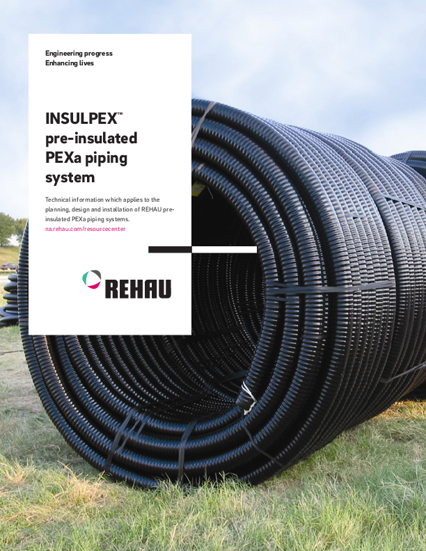
Engineering progress Enhancing lives
INSULPEXTM pre-insulated PEXa piping system
Technical information which applies to the planning, design and installation of REHAU preinsulated PEXa piping systems. na.rehau.com/resourcecenter

TABLE OF CONTENTS

1 . . . . . Scope. . . . . . . . . . . . . . . . . . . . . . . . . . . . . . . . . .  3
2 . . . . . Design Considerations . . . . . . . . . . . . . . . . . . .  4
3 . . . . . System Overview. . . . . . . . . . . . . . . . . . . . . . . .  5 3.1 . . . .  System Advantages. . . . . . . . . . . . . . . . . . . . . . . . . . . . 5 3.2 . . . .  Application . . . . . . . . . . . . . . . . . . . . . . . . . . . . . . . . . . . 5

6 . . . . . System Design. . . . . . . . . . . . . . . . . . . . . . . . .  14 6.1 . . . .  Step 1: Determine Length. . . . . . . . . . . . . . . . . . . . . . . 14 6.2 . . . .  Step 2: Estimate Total Heat Loss . . . . . . . . . . . . . . . . .14 6.3 . . . .  Step 3: Estimate Flow Rate . . . . . . . . . . . . . . . . . . . . . 15 6.4 . . . .  Step 4: Determine Pipe Size. . . . . . . . . . . . . . . . . . . . .15 6.5 . . . .  Step 5: Calculate Heat Loss . . . . . . . . . . . . . . . . . . . . .15 6.6 . . . .  Step 6: Calculate Head Loss . . . . . . . . . . . . . . . . . . . . 16

4 . . . . . System Components. . . . . . . . . . . . . . . . . . . . .  6 4.1 . . . .  INSULPEX� Pipe . . . . . . . . . . . . . . . . . . . . . . . . . . . . . . 6 4.2 . . . .  SDR11 Compression-Sleeve Fitting . . . . . . . . . . . . . . . 9 4.3 . . . .  INSULPEX Insulation Kits . . . . . . . . . . . . . . . . . . . . . . . 9 4.4 . . . .  INSULPEX Installation Accessories . . . . . . . . . . . . . . 10 4.5 . . . .  RAUTOOLTM PEXa Pipe Installation Tools . . . . . . . . . . 10

7 . . . . . System Testing. . . . . . . . . . . . . . . . . . . . . . . . .  18

5 . . . . . System Planning. . . . . . . . . . . . . . . . . . . . . . . . . 11 5.1 . . . .  Trench Installation . . . . . . . . . . . . . . . . . . . . . . . . . . . . 11 5.2 . . . .  Above-Ground Installation. . . . . . . . . . . . . . . . . . . . . . 12 5.3 . . . .  Building Penetration. . . . . . . . . . . . . . . . . . . . . . . . . . . 12 5.4 . . . .  Thermal Expansion. . . . . . . . . . . . . . . . . . . . . . . . . . . .13 5.5 . . . .  Transition to Building Service Piping. . . . . . . . . . . . . . 13

For updates to this publication and the most current technical instructions, safety information and manufacturer's recommendations, visit na.rehau.com/resourcecenter
02

1. SCOPE

This technical information applies to the planning, installation and connection of REHAU pre-insulated PEXa piping systems using PEXa crosslinked polyethylene pipe.
Persons using this guide must be experienced and appropriately licensed designers, with a working knowledge of local codes, principles and practices for design and installation of flexible distribution piping systems.
The information presented in this guide is intended to demonstrate general methods and is not specific to your project conditions. It is the responsibility of the designer to check the prevailing local codes and to verify that technical information presented in this guide is appropriate for a particular installation. This guide does not supersede the recommendations of other manufacturers. If there is conflicting information, the designer must consult with the other manufacturer's representative prior to planning, installing and connecting the energy transfer system.
After reading this guide, designers should attend the Skill Builders Complete seminar offered by the REHAU Academy, where design techniques for pre-insulated PEXa piping systems are more fully explored. Designers should also periodically check the REHAU Resource Center for the latest updates.
This guide should be used in conjunction with the REHAU Sustainable Building Technology Product Catalog which provides a detailed description of each system component, REHAU PEXa Piping Systems Pressure Loss Tables and REHAU INSULPEX Installation Guide. The designer should also review the REHAU PEXa Limited Warranty and pertinent supplemental REHAU Technical Bulletins before beginning to design an energy transfer system.
If you do not have prior experience with pre-insulated PEX piping systems or require additional assistance, please contact your regional REHAU sales representative.

This symbol and the signal words DANGER, WARNING or CAUTION alert you to personal injury hazards. If you don't avoid the hazardous situation: � DANGER! Will result in death or serious injury � WARNING! Could result in death or serious injury � CAUTION! Can result in minor or moderate injury
The signal word NOTICE is used to help you avoid property damage. We cannot warn of all hazards; you must also use your own good judgment.

03

2. DESIGN CONSIDERATIONS
The most critical points in a pre-insulated PEXa piping system design are:
� To ensure the flow requirement and pressure loss are within the circulator's performance capability.
� To design the buried depth to use energy efficiently and to avoid heaving of the pipe in the coldest months.
� To transition to building service piping immediately upon entering the building and to properly secure the transition fitting.
04

3. SYSTEM OVERVIEW
In view of the increasing need to minimize CO2 emissions as much as possible, local heating supply technology is becoming increasingly important. Pioneering technologies, combining optimal functionality with low energy losses, are the basis for REHAU INSULPEX pre-insulated PEXa piping systems. 3.1 System Advantages INSULPEX is flexible, pre-insulated PEXa piping with closed-cell polyurethane (PU) foam bonded insulation. � Flexible pipe system ensures cost-effective heat distribution � Minimal linear expansion, as pipe layers are fully bonded
together � No need for expansion bellows or compensators � Fully bonded pipe layers limit water penetration to absolute
minimum � System components for a variety of applications 3.2 Applications INSULPEX is used predominantly below ground and is ideal for applications including: - District heating - Energy transfer - Snow and ice melting - Chilled water - Process piping - Hydronic piping - Geothermal - Industrial and agricultural - Outdoor wood furnace
05

4. SYSTEM COMPONENTS

4.1 INSULPEX Pipe INSULPEX components � PEXa carrier pipe, insulation and jacket � are explained in detail in this section.
4.1.1 PEXa Carrier Pipes RAUTHERMTM crosslinked polyethylene (PEXa) pipes are manufactured using REHAU's high-pressure peroxide extrusion method that typically yields the highest, most consistent level of crosslinking. Pioneered by REHAU in 1968, PEXa technology enhances flexibility and thermal memory, providing ease of handling and kink repair while supporting the use of REHAU SDR11 compression-sleeve fittings.
Standards RAUTHERM is REHAU's trade name for metric-sized SDR11 PEXa pipes in accordance to ISO 15875 and DIN 16892.

3 1
2

Long Term Strength The pressure and temperature ratings apply to the application of REHAU PEXa pipe for conveying heating and cooling water at a 2.0 safety factor on allowable working pressure.

Fig. 4.1: INSULPEX main components: PEXa carrier pipe (1), insulation (2) and jacket (3)

INSULPEX with RAUTHERM carrier pipe

maximum pressures

design factors

and temperatures

125 psi @ 73.4�F (860 kPa @ 23�C)

0.50

80 psi @ 180�F (550 kPa @ 82.2�C)

0.50

65 psi @ 200�F (450 kPa @ 93.3�C)*

0.50

*Elevated Temperature Applications According to the REHAU PEXa Limited Warranty, the carrier pipe warranty period of 25 years is for operating conditions at or below 180�F (82.2�C) in permitted applications when the handling, use, installation and maintenance continually complies with all REHAU technical guidelines. REHAU defines Elevated Temperature Applications as those with operating conditions greater than 180�F (82.2�C). When RAUTHERM pipes are planned to be operated in Elevated Temperature Applications, contact REHAU Engineering to verify your project conditions comply with the REHAU PEXa Limited Warranty.

Oxygen Resistance In pre-insulated PEXa systems, hundreds or thousands of feet of pipe are used, providing a large surface area for potential permeation of oxygen (O2). The uncontrolled diffusion of oxygen into closed systems is an important issue for system designers.
INSULPEX piping systems consisting of RAUTHERM carrier pipe limit permeability as defined within DIN 4726, the accepted German standard for limiting oxygen transmission. Without a diffusion barrier, oxygen can pass through the pipe wall, dissolve in the heating water and corrode any ferrous components such as pipes, valves, pumps and boilers.
NOTICE: Use only oxygen barrier pipe in closed systems with ferrous components. Excessive oxygen in closed system may damage ferrous components resulting in leaks and operational failures.

06

Chemical Compatibility REHAU's PEXa carrier pipe is compatible with ethylene and propylene glycol, and common corrosion inhibitors used in hydronic piping systems. Chemicals that may damage this pipe include (but are not limited to): � Adhesives - Oil or petroleum-based products - Paints - Solvents - Oxidizing agents (e.g., bleach) - Disinfectants (e.g., separate dosing unit integrated into building
distribution system)
Many factors, such as exposure time, temperature, pressure and other operating parameters, can influence the performance of a pipe that is exposed to a chemical. To determine the impact of a particular chemical, short- and long-term pressure testing may be required. In some cases, a pipe may be resistant to short-term exposure to the chemical, but not resistant to continuous exposure. Each chemical must be evaluated individually.
NOTICE: Check compatibility before allowing chemicals to come in contact with the exterior or interior of PEXa carrier pipes. Chemicals may damage the pipe resulting in leaks and operational failures.

Friction Loss The pressure loss in the pre-insulated PEXa system depends on the flow rates, water temperatures and the properties of the fluid. Use the REHAU LoopCAD� Software which includes a built-in calculator to determine pipe pressure losses for the given conditions. Or refer to the REHAU PEXa Piping Systems Pressure Loss Tables for the applicable pressure loss table presented at typical flow rates and water temperatures for propylene glycol. The pressure loss in the PEXa carrier pipe is based on the application of the D'Arcy-Weisbach equation and fluid properties from ASHRAE Fundamentals.

4.1.2 Pipe Insulation The co-extruded, closed-cell, polyurethane (PUR) foam insulation in INSULPEX provides excellent strength properties while maintaining flexibility. In addition, the polyurethane has low thermal conductivity and very low water absorption.

Table 4.1: Properties of Pipe Insulation

Property Maximum Thermal Conductivity Closed Cellular Structure Maximum Water Absorption

Value

Standard

0.15 Btu�in/ft2��F�hr EN 15632

0.022 W/m��K

>=90%

�

<10% (vol)

EN 15632

Ultraviolet Resistance Plastics are susceptible to damage from exposure to the ultraviolet (UV) radiation in sunlight. REHAU's PEXa carrier pipes can be designed to protect against short-term UV damage, but after some time, UV radiation will reduce the lifespan of the pipe. The extent of the reduction depends on factors such as temperature and pressure, and chlorination levels in potable water. If excessive UV exposure occurs, the PEXa carrier pipes may not last their full design life. REHAU has performed extensive testing of PEXa carrier pipes exposed to natural sunlight, leading to the maximum UV exposure times expressed in accumulated days. Once the pipes leave the manufacturing plant, any exposure to UV, including transportation and storage by the wholesaler, is part of the accumulated exposure time. Maximum accumulated exposure times are listed in the pertinent REHAU Technical Bulletin.
Exposure of the PEXa carrier pipe to UV radiation should be prevented. Protective caps or bags placed on the ends of INSULPEX should not be removed until ready to install.

4.1.3 Pipe Jacket The jacket of INSULPEX is made of corrugated low-density polyethylene (LDPE) allowing the pipe to withstand rugged job site conditions. The corrugated shape is instrumental in the pipe's resistance to thermal expansion when buried. The LDPE jacket contains a minimum 2.5% carbon black.

Table 4.2: Properties of Pipe Jacket

Property Maximum UV Resistance

Value 2 years

Standard �

INSULPEX may be stored outdoors for a maximum accumulated time of two years, including installation time. During outdoor storage the ends of INSULPEX must be covered with UV-blocking caps or bags to protect the PEXa carrier pipes from UV exposure. During construction, keep caps in place until it is time to make a connection, and replace them on remaining pipe ends.

NOTICE: Failure to follow maximum UV exposure limits may damage the pipe resulting in leaks and operational failures, and will negate any warranty provided by REHAU for RAUTHERM pipes.

07

4.1.4 INSULPEX Sizes

Table 4.3: INSULPEX With Metric-sized RAUTHERM SDR11 Carrier Pipe

Nominal

PEXa Carrier Pipe

Average Outer Minimum Wall

Inner

Size

Diameter

Thickness

Diameter

d

s

in.

in (mm)

One-pipe system

in (mm)

in (mm)

25

0.990

0.091

0.809

(25.2)

(2.3)

(20.6)

32

1.266

0.114

1.037

(32.2)

(2.9)

(26.4)

40

1.583

0.146

1.291

(40.2)

(3.7)

(32.8)

50

1.978

0.181

1.616

(50.3)

(4.6)

(41.1)

63

2.492

0.228

2.035

(63.3)

(5.8)

(51.7)

75

2.967

0.268

2.431

(75.4)

(6.8)

(61.8)

90

3.561

0.323

2.915

(90.5)

(8.2)

(74.1)

110

4.350

0.394

3.563

(110.5)

(10.0)

(90.5)

125

4.945

0.449

4.047

(125.6)

(11.4)

(102.8)

140

5.537

0.500

4.537

(140.7)

(12.7)

(115.3)

Two-pipe system

25 + 25

0.990

0.091

0.809

(25.2)

(2.3)

(20.6)

32 + 32

1.266

0.114

1.037

(32.2)

(2.9)

(26.4)

40 + 40

1.583

0.146

1.291

(40.2)

(3.7)

(32.8)

50 + 50

1.978

0.181

1.616

(50.3)

(4.6)

(41.1)

63 + 63

2.492

0.228

2.035

(63.3)

(5.8)

(51.7)

Capacity gal/ft (l/m)

Pipe Jacket

Outer

Wall

Diameter Thickness

D

in (mm)

in (mm)

0.0263 (0.327) 0.0434 (0..539) 0.0672 (0.835) 0.1052 (1.307) 0.1683 (2.091) 0.2384 (2.961) 0.3425 (4.254) 0.5123 (6.362) 0.6537 (8.120) 0.8300 (10.31)

3.6 (91) 3.6 (91) 3.6 (91) 4.4 (111) 5.0 (126) 5.6 (142) 6.4 (162) 6.4 (162) 7.2 (182) 8.0 (202)

0.083 (2.1) 0.083 (2.1) 0.083 (2.1) 0.091 (2.3) 0.106 (2.7) 0.118 (3.0) 0.125 (3.2) 0.125 (3.2) 0.130 (3.3) 0.130 (3.3)

2 x 0.0263 (2 x 0.327) 2 x 0.0434 (2 x 0.539) 2 x 0.0672 (2 x 0.835) 2 x 0.1052 (2 x 1.307) 2 x 0.1683 (2 x 2.091)

4.4 (111) 4.4 (111) 5.0 (126) 6.4 (162) 7.2 (182)

0.091 (2.3) 0.091 (2.3) 0.106 (2.7) 0.125 (3.2) 0.130 (3.3)

INSULPEX Weight Minimum
Bend Radius lb/ft (kg/m) ft (m)

0.8 (1.2) 0.9 (1.4) 1.0 (1.5) 1.5 (2.2) 1.9 (2.9) 2.3 (3.4) 3.1 (4.6) 3.4 (5.1) 4.3 (6.4) 5.1 (7.6)

2.6 (0.8) 2.6 (0.8) 2.6 (0.8) 3.0 (0.9) 3.3 (1.0) 3.5 (1.1) 4.0 (1.2) 4.0 (1.2) 4.5 (1.4) 4.5 (1.4)

1.2 (1.9) 1.4 (2.1) 1.8 (2.7) 2.9 (4.3) 3.6 (5.3)

3.0 (0.9) 3.0 (0.9) 3.9 (1.2) 4.5 (1.4) 4.5 (1.4)

D

D

d Fig. 4.2: INSULPEX outline diagram 08

4.2 SDR11 Compression-Sleeve Fitting SDR11 fittings are available as couplings, reducing couplings, threaded adapters, welding adapters, elbows and tees. SDR11 fittings are manufactured from brass, bronze and carbon steel depending on size and configuration.

4.3 INSULPEX Insulation Kits Buried fittings must be protected. Insulation kits are designed to seal the connection of two or more INSULPEX pipes. Kits are compatible with SDR11 compression-sleeve fittings. Kits are available in coupling, elbow and tee configurations.

SDR11 fittings are sized according to the corresponding PEXa carrier pipe sizes. Metric-sized SDR11 compression-sleeve fittings are in accordance with ISO 15875.

Steel SDR11 fittings are available as weldable ends and can be custom welded into tees or elbows. Carbon steel SDR11 fittings can be used for closed systems with air removal devices.

SDR11 compression-sleeve fittings have the following

1

2

advantages:

- Reliable and easy to install

- Connections do not require flame, heat or solvent

- Ready for service as soon as they are connected

1

2

3

4

Fig. 4.4:

Coupling shroud insulation kit (1), coupling shell insulation kit (2),

elbow shell insulation kit (3), tee shell insulation kit (4)

3

4

Fig. 4.3: SDR11 compression-sleeve fitting (1), fitting inserted in expanded pipe (2), SDR11 joint (3) and cutaway (4)

09

4.4 INSULPEX Installation Accessories Accessories are used in a variety of energy transfer construction methods.
Heat Shrink End Cap A watertight, heat-shrinkable pipe end covering for moist areas used to protect the insulation when transitioning INSULPEX to building service piping.

4.5 RAUTOOL PEXa Pipe Installation Tools RAUTOOLS provide fast, easy and professional installations, and are required to assemble joints comprising REHAU pipes and SDR11 compression-sleeve fittings. Additional information on tools is available in the REHAU INSULPEX Installation Guide.
Pipe Cutting Tools Cutters provide a clean, square and accurate cutting of PEXa pipe.
Pipe Expansion Tools PEXa pipe is cold-expanded, then an insert fitting is pushed into the pipe. Pipe expansion occurs via a manual, battery-operated or hydraulic tool and a special geometry expander bit.

SDR11 Compression-sleeve Tools The sleeve is compressed over PEXa pipe and insert fitting to assemble the joint. Joint compression occurs via a manual, battery- operated or hydraulic tool and a set of compression jaws.

Slip-On End Cap A light duty, plastic pipe end covering to protect insulation against dust when transitioning INSULPEX to building service piping.

Wall Sealing Ring A flexible, neoprene ring for watertight sealing of INSULPEX in a wall penetration.
10

5. SYSTEM PLANNING

Presented below are specific installation details that the system Table 5.1: One-pipe Trench Dimensions

designer must be aware of.

H-20 Load

Excavated Material

5.1. Trench Installation Do not install INSULPEX in soil or groundwater conditions which are thought or known to be contaminated with fuels, organic compound, solvents or other possible hazards, as these substances could permeate the pipe and contaminate the water or damage the integrity of the pipe. If contamination is suspected, a chemical analysis of the soil or groundwater must be performed to determine the contaminant and its compatibility with INSUL-

Max. Depth 8.5 ft (2.6 m)

Road Bed

Minimum Cover 24 in (60 cm)
12 in (30 cm)

4 in (10 cm) 4 in (10 cm)
4 in (10 cm)
B

4 in (10 cm)

Warning Tape

Sand

Trench

Edge

A

Unexcavated

Earth

INSULPEX Two-pipe system

PEX. A minimum of 4 in (10 cm) of sand should surround INSULPEX in

Jacket OD (mm) 91

Depth A in (cm) 31 (80)

Width B in (cm) 12 (30)

the trench. The sand protects the INSULPEX from sharp objects 111

33 (85)

12 (30)

and is crucial to the thermal compensation of the system.

126

33 (85)

14 (36)

142

33 (85)

14 (36)

Native soil can be used for the remaining fill, as long as there are 162

35 (90)

14 (36)

no large (greater than 1 1/2 in [4 cm]), frozen or sharp objects

182

35 (90)

15 (38)

such as rocks or debris. Compact the fill material by hand to a

202

38 (95)

16 (40)

height of at least 6 in (15 cm) above the INSULPEX. Above the

hand-compacted fill, a mechanical device can be used to com-

pact the soil.

Table 5.2: Two-pipe Trench Dimensions
H-20 Load

INSULPEX is suitable for H-20 loading at depths ranging from

Excavated Material

2 ft (60 cm) from the roadbed to a maximum 8.5 ft (260 cm). See Figs. 5.1 and 5.2 for H-20 trench dimensions.
For applications where loading is not a concern, the trench depth should be a minimum of 16 in (40 cm). For better thermal

Max. Depth 8.5 ft (2.6 m)
Minimum Cover 24 in (60 cm)
12 in (30 cm)

Road Bed

4 in (10 cm)

Warning Tape
Sand Trench
Edge A
Unexcavated Earth

performance an increased burial depth is recommended. Burying the pipe below the frost line can prevent heaving and improve thermal performance.

4 in (10 cm) 4 in (10 cm)
B

INSULPEX One-pipe system
4 in (10 cm) 4 in (10 cm)

Jacket OD (mm) 91 111 128 142 162 182 202

Depth A in (cm) 31 80) 33 (85) 33 (85) 33 (85) 35 (90) 35 (90) 38 (95)

Width B in (cm) 20 (50) 22 (55) 22 (55) 24 (60) 26 (65) 26 (65) 28 (70)

11

5.2 Above-Ground Installation Above ground installations of INSULPEX (protected from direct exposure to UV radiation) must be properly supported with either fixed or sliding supports. Local code may define the maximum distances between support devices, otherwise, horizontal and vertical runs should be supported every 40 in (1 m). INSULPEX may not be used for permanent, unsheltered outdoor exposure.

Table 5.3: Wall Breakthrough Dimensions H

5.2.1 Fixed Supports Fixed supports are typically applied at fitting locations. When using a fixed support, follow the support manufacturer's recommendation for installation. Place the fixed support on the body of the fitting, not on the INSULPEX jacket nor on the SDR11 compression sleeve.
5.2.2 Sliding Support Device To allow for expansion and contraction, support devices for INSULPEX should allow for movement with slide linings. Support devices must accommodate the outside diameter of INSULPEX and not squeeze the pipe unnecessarily. Make sure the material contacting the INSULPEX is not abrasive and does not allow sharp edges to protrude into the INSULPEX. The installer should place 3 sliding supports at 90� bends, observing the minimum bend radius.
5.3 Building Penetration For penetrating through an exterior wall there are two options, bored hole and wall breakthrough. Both options require the use of the wall sealing ring and require filling in the hole with concrete.

3 in

(80 mm)

D

min

4 in

3 in

(100 mm)

D

(80 mm)

min

min

L

Jacket OD mm 91 111 126 142 162 182 202

L min

in

cm

20

50

20

50

21 3/4 55

23 3/4 60

25 1/2 65

25 1/2 65

27 1/2 70

Table 5.4: Bored Hole Dimensions

H

in

cm

10

25

12

30

12

30

13 3/4 35

13 3/4 35

13 3/4 35

15 3/4 40

For a wall breakthrough make an opening with the dimensions from Table 5.3.

For bored holes make hole(s) with the dimensions from Table 5.4.

Linked-type sealing rings suitable for polymer pipes can also be used when following manufacturer's instructions. Linked seals do not use mortar and do not require a wall sealing ring, however the bored hole should still be sealed as described above.

Jacket OD mm 91 111 126 142 162 182 202

A min

in

cm

9

23

10

25

10 3/4 27

11 1/2 29

12 1/4 31

12 3/4 32

13 3/4 35

D1

in cm

8

20

9

22

9 1/2 24

10 1/4 26

11

28

11 1/2 29

12 1/2 32

12

5.4 Thermal Expansion The unique property of INSULPEX is that it is self-compensating when buried in accordance with the instructions in the REHAU INSULPEX Installation Guide. The friction force between the fill sand around the INSULPEX and the outer casing is sufficient to limit thermal expansion of the pipe under typical operating conditions.

Table 5.5: Transition to Building Service Piping

4 in (100 mm) maximum

B
3 in (80 mm) minimum

3 in (80 mm) minimum

However, when INSULPEX is installed in a non-buried application, the system design must account for the natural tendency of the pipe to expand due to temperature change.
5.5 Transition to Building Service Piping To keep the thermal expansion within acceptable limits when connecting to a building, INSULPEX pipes should not extend beyond the exterior wall into the building more than the distances specified in Table 5.5. If the end caps are fully inside the wall, these distances can be reduced by 2.3 in (6 cm). The PEXa carrier pipe requires properly designed and installed fixed brackets inside the building suitable for the thermal expansion forces. Fixed brackets may be attached to the fitting body, but not to the SDR11 compression sleeve.

Fixed Point

SDR11 Transition
Fitting

End Cap

Wall Sealing INSULPEX Ring

Pipe Size 25 mm 32 mm 40 mm 50 mm 63 mm 75 mm 90 mm 110 mm 125 mm 140 mm

Maximum B Distances

Anchor Force SDR11 Transition Fitting

lbf

kN

in

cm

410 1.8

10 3/4 27

590 2.6

10 3/4 27

900 4.0

10 3/4 27

1310 5.8

10 3/4 27

1890 8.4

11 3/4 30

2390 10.6

11 3/4 30

2700 12.0

11 3/4 30

2840 12.6

11 3/4 30

3510 15.6

13 3/4 35

4410 19.6

13 3/4 35

13

6. SYSTEM DESIGN

This section outlines the procedures required for a complete INSULPEX system design. A full analysis of system performance and requirements involves the following design elements: � INSULPEX length determination � Total heat load estimation � Flow rate estimation � INSULPEX size determination � INSULPEX heat loss calculation � INSULPEX pressure loss calculation

6.1 Step 1: Determine Length � Calculate the distance of the INSULPEX route in feet. When
planning the route, be sure to check with utility companies and other trades to account for obstructions. � Add 4.5 ft (1.4 m) of length for every 90� bend in the pipe. � Be sure to account for both the supply and return legs of the route if you are not using two-pipe INSULPEX. � Ensure there is at least 20 in (51 cm) of clearance (from pipe end), if using the RAUTOOL G2 toolkit.

The detailed descriptions that follow are expressed in terms of heat load and heat loss, however the same principles and procedures apply to cooling loads and heat gains.

Terms and Symbols

Fig. 6.1: Tool clearance

Cp = specific heat of fluid (Btu/lb��F) Db = depth of burial to centerline of INSULPEX pipe (in) L = INSULPEX length (ft)
 = fluid density (lb/gallon)
qINS = heat loss through INSULPEX (Btu/h)

Observe the minimum bend radii listed in Chapter 4. If a coupling or tee connection must be placed on a bend, ensure that the radius is 13 ft (4 m) or more
INSULPEX

SDR11 coupling or tee

Radius  13 ft (4 m)

qload = heating load of an area or sub-area (Btu/h) qtot = total heating load including loss through INSULPEX (Btu/h) Rtot = total thermal resistance (h�ft��F/Btu) Tave = average of system supply and return fluid temperatures (�F) Tsoil = soil temperature (�F) T = difference between supply and return fluid temperatures (�F)

Fig. 6.2: Bend radius at connection
6.2 Step 2: Estimate Total Heat Load A system heat load calculation should take into account heat lost through the INSULPEX pipe. An initial rough estimate of the total heat loss can be obtained by using:
qtot = qload +10(Btu/h ft) x L
This assumes a loss of 10 Btu/h per foot of pipe, based on: � Average INSULPEX size � Tave of 135�F, Tsoil of 50�F � Medium soil thermal conductivity condition

Example, given: qload = 600,000 Btu/h L = 800 ft (400 ft supply + 400 ft return) qtot = 600,000 + 10 x 800 = 608,000 Btu/h 14

6.3 Step 3: Estimate Flow Rate Having estimated the total heat load, qtot the designer may proceed with the flow rate (where 60 converts hours to minutes) estimation by using:

6.5 Step 5: Calculate Heat Loss Once the appropriate pipe size has been identified, the following equations are used to more precisely calculate heat loss through buried pipe:

USGPM = qtot/( x Cp x 60 x T)
The designer of the heating system should provide the T. This equation calculates the required flow rate of the heating fluid in the INSULPEX based on fluid properties and desired T.

qINS =(Tave - Tsoil)/Rtot
Note: For non-buried applications, use a suitable heat loss method. INSULPEX may not be used for permanent, unsheltered outdoor exposure.

Example continues, given: qtot = 608,000 Btu/h T = 35�F Water as a heating fluid
( = 8.22 lb/gallon, Cp = 1 Btu/lb��F @ 135�F [57�C])

Example continues, given: Supply fluid temperature = 150�F Return fluid temperature = 120�F
Tave = (150 + 120)/2 = 135�F

USGPM = (608,000 Btu/h)/(8.22 lb/gallon x 1 Btu/lb �F x 60 min/hr x 35�F) = 35 gpm
Note: If the heating fluid includes antifreeze, be sure to use the correct values of density and specific heat corresponding to the type and concentration of antifreeze in the water. Table 6.1 shows the combined properties of common heating fluid mixtures and concentrations.

Use the lowest ground temperature if you are calculating heat loss, or the highest temperature for heat gain.
Note: The lowest or highest temperature does not necessarily occur in winter or summer. In some locations the most extreme ground temperature lags by a season.

6.4 Step 4: Determine Pipe Size Correct sizing of the system pump(s) and other components requires selection of the appropriate INSULPEX carrier pipe size. The INSULPEX pipe should be chosen based on the estimated flow rate and the resulting head loss (see REHAU PEXa Piping Systems Pressure Loss Tables). The suggested range of head loss through the pipe is 10 to 20 ft of head. Additional losses through system components must be taken into account when sizing pump(s) and other equipment.

Table 6.1: Glycol Properties

Glycol Content

 (lb/gal)

@ 100�F (37�C) Propylene Ethylene

10%

8.37

8.41

20%

8.45

8.55

30%

8.52

8.67

40%

8.58

8.79

50%

8.63

8.90

Source: ASHRAE Fundamentals

C (Btu/lb �F) Propylene Ethylene

0.981

0.957

0.959

0.922

0.931

0.883

0.899

0.843

0.861

0.800

 x Cp x 60

Propylene Ethylene

492

483

486

473

476

459

463

444

446

427

15

Rtot: Total Thermal Resistance The total thermal resistance must be determined, see Table 6.3. The following variables must be determined to derive an accurate Rtot value: � Db: Depth of Bury to Pipe Centerline
Determine the depth from the top of the trench to the horizontal centerline of the pipe(s) in inches. � Soil Type Thermal conductivity of the soil depends on factors such as soil composition, particle size and nature, water and air content and drainage. For the purposes of this heat loss calculation, we will classify three kinds of soil, shown in Table 6.2.

Table 6.2: Thermal Conductivity of Soil

Soil Type Dry Medium
Moist

Thermal

Conductivity

Description

Btu�in/h�ft2��F

Well to excessively drained,

1

coarse-textured particles

Well drained with moderately fine

8

or medium-textured particles, or,

poorly drained with moderately

coarse-textured soil

Poor to very poorly drained fine-

textured soils or peats

15

Note: The REHAU INSULPEX Installation Guide states that the trench should be filled with sand around the INSULPEX. However, for the purposes of the calculation, soil type selection should be based on the native soil properties.
Once the heat loss through the INSULPEX is known, calculate a more precise total heat load by using: qtot = qload + qINS
Compare this to the qtot estimated in the total heat load estimation. If the values differ by more than 5%, use the new qtot to calculate a corrected flow rate. Then, using the new flow rate, verify that the appropriate pipe size has been chosen.
Example continues, given: INSULPEX 63 mm Db = 39 in. to centerline Rtot/L of 8.0 h�ft��F/Btu

6.6 Step 6: Calculate Head Loss Refer to the pressure tables to calculate the pressure loss of the fluid in the INSULPEX pipes. Find the table that corresponds most closely to the amount of glycol in the fluid, if any. Find the intersection of the row corresponding to the flow rate of the fluid, and the column of the correct fluid temperature and pipe size. The number at the intersection is the psi loss per 100 ft of INSULPEX pipe. Multiply that number by the number of 100's of feet of pipe in the system, as shown:
Example continues, given: 0.89 psi loss per 100 ft @ Tave = 120�F 0.79 psi loss per 100 ft @ Tave = 180�F
Through linear interpolation this calculates to: 0.85 psi loss per 100 ft @ Tave = 135�F

qtot = 600,000 + (135 - 50) x 800/8.0 = 608,500 Btu/h

Pressure loss = 0.85 x 8 = 6.8 psi

The design must ensure the flow requirement and pressure loss are within the circulator's performance capability. To express pressure loss in feet of head, multiply by 2.307.

16

Table 6.3: Total Thermal Resistance for INSULPEX

Carrier Pipe/ Outer Jacket One-pipe system 25 / 91
32 / 91
40 / 91
50 / 111
63 / 126
75 / 142
90 / 162
110 / 162
125 / 182
140 / 202
Two-pipe system 25 + 25 / 111
32 + 32 / 111
40 + 40 / 126
50 + 50 / 162
63 + 63 / 182

Soil Condition
Dry Medium Moist Dry Medium Moist Dry Medium Moist Dry Medium Moist Dry Medium Moist Dry Medium Moist Dry Medium Moist Dry Medium Moist Dry Medium Moist Dry Medium Moist
Dry Medium Moist Dry Medium Moist Dry Medium Moist Dry Medium Moist Dry Medium Moist

Total Thermal Resistance Per Foot of Pipe Rtot/L (h�ft��F/Btu) Depth of Bury to INSULPEX Centerline

19 in

27 in

39 in

51 in

75 in

105 in

(48 cm)

(69 cm) (99 cm) (130 cm) (190 cm) (266 cm)

24.9

26.2

27.5

28.6

30.0

31.3

17.0

17.2

17.3

17.4

17.6

17.8

16.5

16.6

16.6

16.7

16.8

16.9

21.7

23.0

24.4

25.4

26.9

28.2

13.9

14.0

14.2

14.3

14.5

14.6

13.4

13.4

13.5

13.6

13.7

13.7

18.9

20.2

21.6

22.6

24.1

25.3

11.0

11.2

11.3

11.5

11.6

11.8

10.5

10.6

10.7

10.7

10.8

10.9

18.1

19.4

20.8

21.8

23.2

24.5

10.7

10.9

11.0

11.2

11.3

11.5

10.2

10.3

10.4

10.4

10.5

10.6

16.4

17.7

19.1

20.1

21.6

22.8

9.4

9.5

9.7

9.8

10.0

10.1

8.9

9.0

9.0

9.1

9.2

9.3

15.4

16.7

18.0

19.1

20.5

21.8

8.6

8.8

8.9

9.1

9.2

9.4

8.2

8.3

8.3

8.4

8.5

8.6

14.4

15.7

17.0

18.0

19.5

20.8

8.0

8.1

8.3

8.4

8.6

8.7

7.5

7.6

7.7

7.8

7.8

7.9

11.8

13.1

14.5

15.5

16.9

18.2

5.4

5.6

5.7

5.9

6.0

6.2

5.0

5.1

5.1

5.2

5.3

5.4

11.4

12.6

14.0

15.0

16.5

17.8

5.3

5.4

5.6

5.7

5.9

6.0

4.9

4.9

5.0

5.1

5.2

5.2

11.0

12.2

13.6

14.6

16.1

17.3

5.2

5.3

5.5

5.6

5.8

5.9

4.8

4.8

4.9

5.0

5.1

5.1

14.6

15.4

16.0

16.5

17.2

17.9

10.1

10.2

10.2

10.3

10.4

10.5

9.8

9.8

9.9

9.9

9.9

10.0

12.6

13.3

13.9

14.5

15.2

15.9

8.0

8.1

8.2

8.2

8.3

8.4

7.7

7.8

7.8

7.8

7.9

7.9

12.0

12.7

13.3

13.8

14.6

15.2

7.6

7.7

7.8

7.8

8.0

8.0

7.3

7.4

7.4

7.4

7.5

7.5

11.7

12.4

13.0

13.6

14.3

14.9

7.7

7.8

7.9

8.0

8.0

8.1

7.4

7.5

7.5

7.6

7.6

7.7

10.2

11.0

11.6

12.1

12.9

13.5

6.3

6.4

6.5

6.5

6.6

6.7

6.0

6.1

6.1

6.2

6.2

6.2

17

7. SYSTEM TESTING
REHAU only provides the general guidelines for performing a pressure test on a REHAU pre-insulated PEXa piping system as set forth in the INSULPEX Pre-insulated PEXa Piping Installation Guide 855.632.
18

Sales Offices (Toll-free)
Canada Maritimes (800) 565-7342 Qu�bec (800) 361-0830 Ontario (800) 561-9609 Western Canada (800) 944-1011
United States Eastern US (800) 297-6371 Western US (800) 944-1011
Mexico Northern Mexico (818) 121-0130 Central and Southern Mexico (800) 917-3428
Central America Panama (507) 830-5257

REHAU stands behind our products with a 25-year limited warranty on PEXa pipe and fittings. www.na.rehau.com/warranties
Return Policy Each return will be reviewed individually. No material may be returned without our written permission and return authorization number. Only catalogued and resalable items may be returned. The minimum return value will be $100. Product and packaging has to be in resalable condition, all products returned to the distribution center are subject to quality inspection. Materials have to be in original clean and closed packaging (where applicable), packagees must have original labels, customer label must be removed prior to return. Any material which is authorized to be returned will be subject to a minimum twenty-five (25) percent restocking fee.

For updates to this publication, visit na.rehau.com/resourcecenter
The information contained herein is believed to be reliable, but no representations, guarantees or warranties of any kind are made as to its accuracy, suitability for particular applications or the results to be obtained therefrom. Before using, the user will determine suitability of the information for user's intended use and shall assume all risk and liability in connection therewith.
� 2020 REHAU 855.630 US,CA/en 04.2020