AvalonMiner1246 User Manual
Overview
Thank you for purchasing our products. To ensure that you can fully understand and install this product, please read the manual carefully. Please keep it for future reference.
Safety Regulation
⚠️ Warning: in order to prevent equipment damage, falling, electric shock, fire and other accidents that threaten personal safety, please install and use in strict accordance with the instructions. Do not transform the equipment or replace the parts by yourself.
- Do not use power supply beyond rated voltage range.
- Do not place equipment in unstable places.
- When checking and repairing the equipment, please entrust professional personnel to operate.
- When the equipment is abnormal, cut off the power supply quickly and contact the after-sales department.
Hardware Connection
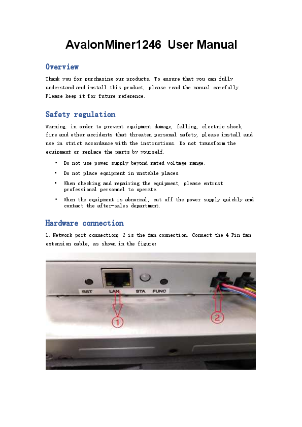
1. Network port connection; 2 is the fan connection. Connect the 4 Pin fan extension cable, as shown in the figure:
[Description of the image showing the rear panel with ports labeled RST, LAN, STA, FUNC. Indicator 1 points to the LAN port, and indicator 2 points to the fan connection.]
3 is the fan connection, connecting the 4Pin fan extension cable; 4 is connecting the power supply with the control board and connecting it with a 6pin cable, as shown in the following figure:
[Description of the image showing connections 3 and 4. Connection 3 is for the fan, and connection 4 is for the power supply to the control board using a 6-pin cable.]
5 is to connect the hash board with the control board with 2 × 7pin cable, as shown below:
[Description of the image showing connection 5, which connects the hash board to the control board using two 7-pin cables.]
Button and Indication LED
Button
RESET: System reset button; system reset will not affect the network series.
FUNC: Function button can be used to restore factory configuration, enter configuration mode, switch on light status during operation, etc.
Indication LED
- After power on, the indicator light flashes red several times ?.
- After the device is started, the indicator light will be yellow ? for about three seconds. During this period, press the func key to enter the configuration mode.
- The indicator LED is green ? under normal mining condition.
- The indicator light is yellow ? during system preparation.
- When the system is overheated, the indicator light is red ?.
- During the operation of the system, through FMS software or manually pressing the func key, the indicator light flashes alternately yellow ? and green ?, and then press again to restore the original color.
- Restore the factory settings: press the func function key when power on, keep it unchanged for five seconds until the red light ? flashes, then press reset or disconnect the power to restart.
Work Mode
The device has two working modes: "normal mode" and "configuration mode". The default mode is DHCP mode.
Normal Mode
In normal operation mode, the device runs in this mode most of the life cycle. In this mode, the network can use DHCP (dynamic acquisition) or static IP, and the factory setting is DHCP.
Configuration Mode
Enter this mode by pressing the func button during the Red LED light at the second time (about 3 seconds) at miner start up. Press the func key before starting and then start the machine. During the red light period (about three seconds), the device will enter this mode.
In this mode, the IP address is static (address: 192.168.168.168, subnet mask: 255.255.255.0). The built-in web services of the device can be accessed through a PC browser, and then the network, mine pool, password, and other information can be configured.
After setting the PC to static IP address: 192.168.168.100 (or any other non-conflicting address in the same network segment), subnet mask: 255.255.255.0, connect the PC to the same network (under the same switch or router, or the PC is directly connected with the device network cable).
1. Right-click [Network Icon], Open network and Internet settings.
2. Change the adapter options, disable WLAN and enable Ethernet.
You can access it with your browser: http://192.168.168.168/. Configure the device (modify static IP, etc.). After the device configuration is completed, it needs to be rebooted. You can click reboot on the left side of the console, or manually power off and restart. Don't forget to switch the network connection so that the device can't access the Internet.
Use the browser to access the modified IP address again. If the indicator is green ?, the operation is correct.
System Setting
Access the built-in web service of the device through the browser and access the device console after login.
User Login
Default username: root, default password: root. After login, you could see the Overview page.
Network Setting (UI Description)
Click Network on the left side of the console to set it as DHCP (dynamic access) or static IP (static).
Note: After saving the network settings, you must restart it. You can click reboot on the left side of the console, or press the reset button to restart. You can also disconnect the power supply and power on again.
Pool Setting (UI Description)
The following figure shows the factory default settings. Normal mode (normal mode / low power consumption mode) or high performance (high power consumption mode) can be selected for work mode. When using high performance mode, please pay attention to using the power supply with higher power output to avoid damaging the hardware.
Note: After saving the configuration of the ore pool, it must be restarted. You can click reboot on the left side of the console, or press the reset button to restart. You can also disconnect the power supply and power on again.
User Password (UI Description)
Default username: root, Default password: root.
Click administrator on the left side of the console to set a new password and save it.
Firmware Upgrade
The upgrade package file format of this device is *.AUP, which can be downloaded through the official website or by contacting customer service. The firmware of the device can be upgraded by FMS software.
Restore to Factory Setting
When power on, press the func key for 5 to 10 seconds, and the system will automatically clear the saved configuration, including network, mine pool, password, and other information. After the configuration is cleared, the white indicator light flashes frequently, indicating that the configuration is restored successfully. After releasing the func key, press the reset button to restart, or disconnect the power supply and power on again. The system will work with the default factory configuration.
Device Guarantee
In the process of use, the equipment may not work normally due to loose connection and abnormal damage of device wire. You can check and remove the fault by yourself. If the device is damaged and within the scope of warranty, you can contact our after-sales personnel for quick repair.
This product provides a 180-day warranty from the time the customer receives the goods, but the following conditions will void the warranty:
- Any physical damage caused by self-dismantling equipment or other reasons (including but not limited to: fracture, fragmentation, missing corner, missing components, etc.)
- Damage caused by lightning strike, voltage surge, etc.
- There are burn marks on the circuit board or the chip is burned.
- Damage caused by water inflow and immersion.
- The circuit board is damp and corroded.
- Beyond the warranty period.
If the above situation happens unfortunately, we can still provide charge maintenance service for your equipment; you can also contact the after-sales personnel to purchase parts for self-repair.
Malfunction
Boot Failure
1. Failure Phenomenon
Fan does not turn or LED light does not light up after starting.
2. Possible Cause
Mine fan wiring loose, Miner control board power supply line disconnected, AC power input is not well connected, power module is broken, control board is broken, power output short circuit protection.
3. Inspection and Repair Methods
- Power on the whole miner, turn on the power switch of the miner, and plug in the network cable connected with the switch (or router). Check that the network port link light flickers. If the network port light is not on, it indicates that the MM control board has no power. It is necessary to check the power line connection, replace the power supply, or check whether there is a short circuit in the power output.
- If the network port light is on, but the LED light of the MM control board is not on, it is necessary to replace the MM control board.
- If the MM control board LED is on but the fan does not rotate, check the fan connection line or replace the fan.
Can't Mine
1. Faulty Phenomenon
- Unable to connect the pool for a long time (more than 5 minutes) after starting up (the miner lights up yellow ? for a long time, does not turn green ? light, has no hashrate).
- The miner pool can be connected after the machine is turned on (the LED light of the miner is green ?), but it has no hashrate.
2. Possible Cause
- Pool configuration error.
- Network configuration error.
- The miner cannot access the Internet.
- The miner power supply has no main circuit output (wiring error, overload, short circuit, or damage).
- The miner's hashboard does not work.
- Overheat protection.
3. Check and Repair
- If the PC cannot be connected to the miner through the network, you can try to restore the factory settings after confirming that the network environment is normal, the network cable is firmly connected, and the miner is started normally. The method of restoring factory settings is shown in Appendix I.
- Check the current firmware version of mining machinery, and it is recommended to update it to the latest version with FMS. See Appendix 3 for the upgrade method.
- Check the status of the hashboard.
- Click log to view the working status as shown in the figure below. It should be in work normally. If it is overheating shutdown, check the fan and ambient temperature as follows.
- Check the number of hash boards shown in the figure below. If the value is 1 or 2, you need to contact our after-sales personnel for handling. If it is 0, you need to check the status of the power supply according to the following.
Miner Log Analysis
1. Check the power supply, temperature, network status, and fan status, and click log in the left column, as shown in the figure below:
[Description of the miner log interface, showing various status indicators and system information.]
Check the following fields in the right interface:
2. NETFAIL: The time of disconnection from the pool is recorded (if it has not been disconnected or has never been connected to the pool, here is all 0). In this record, the odd number items (items 1, 3, 5) are the time of disconnection from the pool, and the even number items (items 2, 4, 6) are the time to restore the connection with the pool. If only the odd number items have data and the even number items are 0, it indicates that the connection with the pool is currently disconnected and has not been restored (usually because the server at the end of the pool is disconnected due to excessive pressure; if it occurs frequently for a long time, other mining pools can be replaced).
3. SYSTEMSTATU: The current working status is recorded. It is in work normally. Among them, hash board: is the number of hash boards in operation. If it is 1 or 2, you need to contact the after-sales department for solution.
4. TAvg: Average chip temperature.
5. Vo: Average chip voltage range: 290mV-350mV.
6. PS: PSU status, include 1-6 items as below:
- Item 1: error code. Other values indicate power failure or output short circuit.
- Item 2: voltage supplied to the control board. The normal value is 12xx.
- Item 3: the voltage supplied to the hash board is normally between 1200 and 1320.
- Item 4: the current output from the power supply to the hash board, which is related to the output power and voltage.
- Item 5: the output power of the power supply to the hash board. The normal value is between 3100 and 3300.
- Item 6: the desired output voltage of the power supply to the hashboard, which is configured by the control board.
If the six parameters in the PS field of the power supply are all 0, it means that the control board cannot communicate with the power supply. Please check the circuit connection. If the connection is correct, the power supply PSU needs to be replaced.
7. Check whether the password configuration of mine pool, miner, and miner is correct. In the background of the mining machine, click pool on the left column to check the configuration of pool, worker, and password. Finally, click the Save button to save the settings, restart the machine, and the configuration takes effect.
8. Check network setting. Click Network on the left. The default configuration is DHCP mode. If all the data here is empty, press F5 to refresh the page. Note that if you need to use static IP configuration, incorrect DNS configuration will cause the miner to lose access to the pool. The commonly used DNS address in China is 114.114.114.114, and the commonly used DNS address outside China is 8.8.8.8.
Note: After modifying the configuration, you need to click the Save button to save the configuration and restart the machine to take effect.
Miner Simple Makeup (Assembly Instructions)
1. The assembled hash boards, case shell, and rear panel are assembled as follows:
[Description of the first image showing the main components of the miner before assembly.]
2. Place the chassis vertically, push the three hash boards onto the guide rail of the chassis, and pay attention to the assembly direction of the hash board components, as shown in the figure:
[Description of the image showing hash boards being inserted into the chassis.]
3. Assemble the hashboards in place, as shown in the figure:
[Description of the image showing hashboards fully seated in the chassis.]
4. Assemble the rear panel to the chassis, pay attention to the assembly direction, as shown in the figure:
[Description of the image showing the rear panel being attached to the chassis.]
5. As shown in the figure, align the opening position of the power supply with the hook position of the power support, press it to level, and push the power supply horizontally according to the arrow direction in the figure until the snap pops up (with a click sound), indicating that the power supply is assembled in place.
[Description of the image showing the power supply being installed, with an arrow indicating the direction of insertion.]
7. Assemble the MM board according to the direction shown in the figure, and pay attention to the position of the locating pin.
[Description of the image showing the MM board being installed.]
8. As shown in the figure, place the conductive aluminum bar (positive pole) at the position shown in the figure, first assemble the set screw, but do not tighten it; tighten other screws, and finally tighten the set screw.
[Description of the image showing the placement of the conductive aluminum bar and the process of tightening screws.]
9. Connect the fan extension cable with the MM board, pay attention to the connection sequence.
[Description of the image showing fan extension cables being connected to the MM board, with numbered indicators.]
10. As shown in the figure, place the conductive aluminum bar (negative pole) at the position shown in the figure, first assemble the set screw, but do not tighten it; tighten other screws, and finally tighten the set screw.
[Description of the image showing the placement of the negative conductive aluminum bar and the tightening of screws.]
11. Connect the voltage regulating line of the power supply to the MM board, and connect the plug of the temperature sensing line to the MM board.
[Description of the image showing the connection of power supply voltage regulating and temperature sensing lines to the MM board.]
12. Hash, as shown in the assembly diagram.
[Description of the image showing the hash boards connected.]
13. Place the upper shell and fix it with flat head screws, as shown in the figure:
[Description of the image showing the upper shell being placed and secured.]
14. Assemble the fan lines in sequence as shown in the figure.
[Description of the image showing the fan lines being connected in sequence.]
[Description of the images showing the connections for the Upper FAN and Below FAN.]
Appendices
Appendix I: Operation Method of Restoring Factory Settings
Method 1
| Step | Remark |
|---|---|
| Confirm that the miner is powered off. Press and hold the func key. | Note that you need to keep the func key pressed all the time. |
| Power on the miner. Keep func pressed until the miner's red LED ? flashes. |
Method 2
| Step | Remark |
|---|---|
| The miner is powered on. Press and hold the func key. | Note that you need to keep the func key pressed all the time. |
| Press the reset button and release. Keep func pressed until the miner's red LED ? flashes. |
Appendix 2: Firmware Version Viewing Method
- View version in the background: Click overview on the left column to see the firmware version number in the figure below.
- View with FMS: Directly view the contents of ver in the far right column of the mine machine list in FMS.
Appendix 3: Operation Method of FMS Batch Upgrade Mining Machine Firmware
Start FMS, select the corresponding miner in the main interface, and click the upgrade button, as shown in the following figure:
[Description of the FMS interface showing the upgrade button.]
In the pop-up dialog box, select the firmware file to be upgraded (.AUP), and click open. As shown in the figure below:
[Description of the file dialog box for selecting the .AUP firmware file.]
There will be progress prompts during the update process:
[Description of the progress indicator during firmware update.]
There will be a prompt at the end of the update. If all are successful, A12 upgrades were successful. Otherwise, all IP addresses that failed to upgrade will be listed. For the miner that failed to upgrade, you can select them according to IP, click the Restart button to restart them, wait for 3 minutes, and then try to upgrade these mining machines again.
Appendix 4: Description of Main Parameters of Log Page
| Field | Name | Remark |
|---|---|---|
| Elapsed | Total running time of miner after starting (unit: s) | |
| Ver | Version number of miner firmware | |
| DNA | The Unique miner ID. | |
| NETFAIL | After connecting the pool successfully, the time to disconnect from the mine pool and the time to resume the connection are also included. | The odd number items (items 1, 3 and 5) are the time of disconnection from the pool, and the even number items (items 2, 4 and 6) are the time for resuming the connection with the pool. The time is in seconds, and the starting time of miner is the 0 second. |
| SYSTEMSTATU | The current status of the system, including the working status and the number of hash boards in operation. | |
| DH | Average calculation error rate. The normal value was 0.6-1.6%. | |
| Temp | Ambient temperature | |
| TMax | Maximum chip temperature in a single hashboard. | |
| TAvg | Average chip temperature in a single hashboard. | |
| Fan1 | Fan 1 rotating speed | |
| Fan2 | Fan 2 rotating speed | |
| FanR | Fan rotating percentage | |
| Vo | Average chip voltage | |
| PS | Power supply status | The meanings of items 1-6 are as follows: Item 1: error code. Other values indicate power failure or output short circuit. Item 2: voltage supplied to the control board. The normal value is 12xx. Item 3: the voltage supplied to the hash board is normally between 1300 and 1448. Item 4: Power supply output current to hashboard. It's related to the output voltage of the power supply. Item 5: the output power of the power supply to the hash board, the normal value is between 3000 and 3200. Item 6: the desired output voltage of the power supply to the force calculation board, which is configured by the control board. If the six parameters in the PS field of the power supply are all 0, it means that the control board cannot communicate with the power supply. Please check the circuit connection. If the connection is correct, the power supply PSU needs to be replaced. |
| PLL0 | The distribution of the 0 th hash board chip at each frequency point. | For example, pll0 [256 589 1259 5786] indicates that there are 256 chips running at frequency 1. There are 5786 chips running at frequency 4. |
| PLL1 | The distribution of the 1 th hash board chip at each frequency point. | |
| GHSmm | Theoretical hashrate, Unit GH/s. | Note: the actual hashrate is the value obtained by deducting DH (calculation error rate) from theoretical hashrate. |
| GHSavg | Average Hashrate at 1 hour. | According to the 1-hour average hashrate by the actual work submitted, this value is closest to the 24-hour average hashrate at the end of the ore pool. |
| WU | Equivalent frequency | |
| Freq | The chip works at different frequency points, and the frequency is the comprehensive equivalent frequency of the whole machine. | |
| Led | White LED status | When you need to find a specific one among many miners, use API to light up the yellow ? green ? flashing LED light of the miner. Here is the status of whether the yellow and green flashing LED is on, 1 indicates that it is on, 0 means it is not. |
| MGHS | The calculation force of a single force plate, unit GH / S | |
| MTmax | Maximum chip temperature in a single hashboard. | |
| MTavg | Average chip temperature in a single hashboard. | |
| TA | ASIC chip numbers | |
| SF0 | The frequency point configuration state of the hashboard 0. | For example, SF0 [500 525 550 575] indicates that frequency point 1 is 500MHz and frequency point 4 is 575mhz. |
| SF1 | The frequency point configuration state of the hashboard 1. | |
| PVT_T0 | Temperature list of all chips of hashboard 0. | |
| PVT_T1 | Temperature list of all chips of hashboard 1. | |
| PVT_V0 | Voltage list of all chips of hashboard 0. | |
| PVT_V1 | Voltage list of all chips of hashboard 1. | |
| PVT_R0 | DH value list of all chips of hashboard 0. | |
| PVT_R1 | DH value list of all chips of hashboard 1. |
Appendix 5: LED Status
1. The state flow process of LED lamp under normal startup condition:
| Status sequence | Durable Time | Red Led Flash | Yellow Led Flash | Green Led Flash |
|---|---|---|---|---|
| 1s | Approximately 20-30s | Long time |
2. LED Status Description
| LED status | Description |
|---|---|
| Off state | The firmware is not running. (no power input possible) |
| Red LED light | The system enters test mode. (or to restore the status after the factory setting operation, it is necessary to release the func key and restart to make the master control enter the normal working state.) |
| Yellow LED light | The system has been started but not connected to the mine pool, the network is blocked or the power supply is abnormal. |
| Green LED light | The system has been started and connected to the mine pool. |
