484390 • Single/Three Phase Vari-Green Motor, Rev. 2, November 2020
File info: application/pdf · 2 pages · 540.89KB
484390 • Single/Three Phase Vari-Green Motor, Rev. 2, November 2020
484390 • Single/Three Phase Vari-Green Motor ... - Greenheck
speed reference from 2-10 V. For more information about this. Vari-Green Motor, please review the Installation, Operation and. Maintenance Manual found by.
Quick Start Guide - Greenheck-USA
Quick Start Guide SingleTree ase Vari-Green Motor Vari-Green Motor Quick Start Guide When delivered, the Vari-Green Motor is pre-programed to run from either an on-board dial or a 0-10 VDC control signal. A 0-1.99 Volt…
Full PDF Document

If the inline viewer fails, it will open the original document in compatibility mode automatically. You can also open the file directly.
Extracted Text
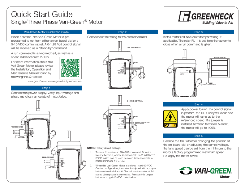
Quick Start Guide
Single/Three Phase Vari-Green� Motor

Vari-Green Motor Quick Start Guide
When delivered, the Vari-Green Motor is preprogramed to run from either an on-board dial or a 0-10 VDC control signal. A 0-1.99 Volt control signal will be received as a "stand-by" command.
A run command is acknowledged, as well as a speed reference from 2-10 V.
For more information about this Vari-Green Motor, please review the Installation, Operation and Maintenance Manual found by following this QR code:
www.greenheck.com/vari-green/vari-green-motors

Step 1

Connect the power supply. Verify Input Voltage and phase matches nameplate of motor/drive.

THREE PHASE
L1 L2 L3

POWER
L1 L2 L3

DISCONNECT

THREE PHASE
L1 L2 L3
DISCONNECT

POWER
L1 L2 L3

Step 2 Connect control wiring to the control terminal.
DIAL ON-BOARD

+24V, 100mA D1, ENABLE
2D D3/A2 +10VDC
A1 COMMON AO/DO OUTPUT COMMON MODBUS RTU� MODBUS RTU+

*JUMPER
BLACK RED WHITE

0-10VDC CONTROL

+24V, 100mA D1, ENABLE
2D D3/A2 +10VDC
A1 COMMON AO/DO OUTPUT COMMON MODBUS RTU� MODBUS RTU+

*JUMPER

RED WHITE

0-10V CONTROL SIGNAL COMMON

SINGLE PHASE L N
DISCONNECT

POWER
L1 L2 L3

SINGLE PHASE
L N

POWER
L1 L2

NOTE: Factory default settings:
1. Terminal 2 is set as an ENABLE command. From the factory there is a jumper from terminal 1 to 2. A START/ STOP switch can be used between these terminals to ENABLE/DISABLE the drive.
2. When this Vari-Green Motor is ordered in a 0-10 VDC Control configuration, the motor is shipped with a jumper between terminal 5 and 6. This will run the motor at full speed when power is connected. Remove this jumper before landing 0-10 VDC control wires.

Step 3 Install motorized backdraft damper wiring, if applicable. The relay RL-1 is set from the factory to close when a run command is given.
MOTORIZED DAMPER

RL�1A RELAY COMMON
RL�1B RELAY N.O. COMMON 250VAC, 6A 30VDC, 5A

N LINE (DAMPER POWER SOURCE)

Step 4
Apply power to unit. If a control signal is present, the RL-1 relay will close and the motor will ramp up to the referenced speed. If a jumper is installed between terminals 5 and 6, the motor will go to 100%.
Step 5
Balance the fan. Whether changing the position of the on-board dial or adjusting the control voltage, the fans speed can be set from the minimum to the motor's factory programmed maximum speed. Re-apply the motor cover.

Quick Start Guide
Single/Three Phase Vari-Green� Motor

Step 6
Review the Installation, Operation and Maintenance Manual for the fan for any specific installation questions. The manual is shipped with the fan, and can also be found at www.greenheck.com or by scanning the QR code located within the drive compartment.

Electrical Data

110 Volt Units, 99-126 V

Supply Voltage Range 230 Volt Units, 180-264 V

400 Volt Units, 342-528 V

5kA Without Fused Disconnect Short Circuit Capacity
100kA With Fused Disconnect

Control Terminal Wiring

Maximum Size

0.05-0.5mm2 / 20-26 AWG

RL-1 Relay

Relay N.O. Contact 250VAC, 6A/30VDC, 5A

Motor Enclosure

Totally Enclosed Fan Cooled, IP54

WARNING
� Do not remove the drive cover for wiring or periodic inspections while power is applied or the unit is in operation. Electric shock may occur from the exposed terminals.
� Wait at least 1 minute after disconnecting the input power before performing any wiring tasks and/or periodic inspections of the drive.
� Operate the Vari-Green motor and control devices with dry hands.
� Do not use this device if power or motor cable is damaged.
� As this is a permanent magnet motor, this motor will generate voltage when the shaft is rotated. Shaft must be locked out for safe servicing.
CAUTION
� Disconnect the input power if the Vari-Green motor has been damaged. Failure to do so may result in fire and/or secondary damage or accidents.
� Do not touch the Vari-Green motor immediately after shutting down or disconnecting it. It can remain hot for a few minutes. Bodily injuries such as skin-burn or damage may occur.
� Do not apply power to a damaged Vari-Green motor or to a Vari-Green motor that is missing parts.
� Do not allow lint, paper, wood chips, dust, metallic chips or other foreign material into the drive as it may cause fire or accident.

Vari-Green Controls

Vari-Green Controls all use a 0-10 VDC control signal to provide a speed reference to Vari-Green Motors. See below for typical Vari-Green wiring. Reference the individual controls Installation, Operation and Maintenance Manual for programing, wiring and troubleshooting of that control.

+24V, 100mA D1, ENABLE
2D D3/A2 +10VDC
A1 COMMON AO/DO OUTPUT COMMON MODBUS RTU� MODBUS RTU+

GND POWER

V+

IN

CONTROL OUT REF OUT
DIGITAL OUTPUT OVERRIDE REMOTE SET POINT

CONSTANT PRESSURE / AIRFLOW CONTROL � INTEGRAL TRANSDUCER

484390 � Single/Three Phase Vari-Green Motor, Rev. 2, November 2020 � Copyright � 2020 Greenheck Fan Corp.