LABOMED MAGNA Microscope with Ceiling Mount User Manual
File info: application/pdf · 69 pages · 15.41MB
Magna User Manual Revision 1.8 copy
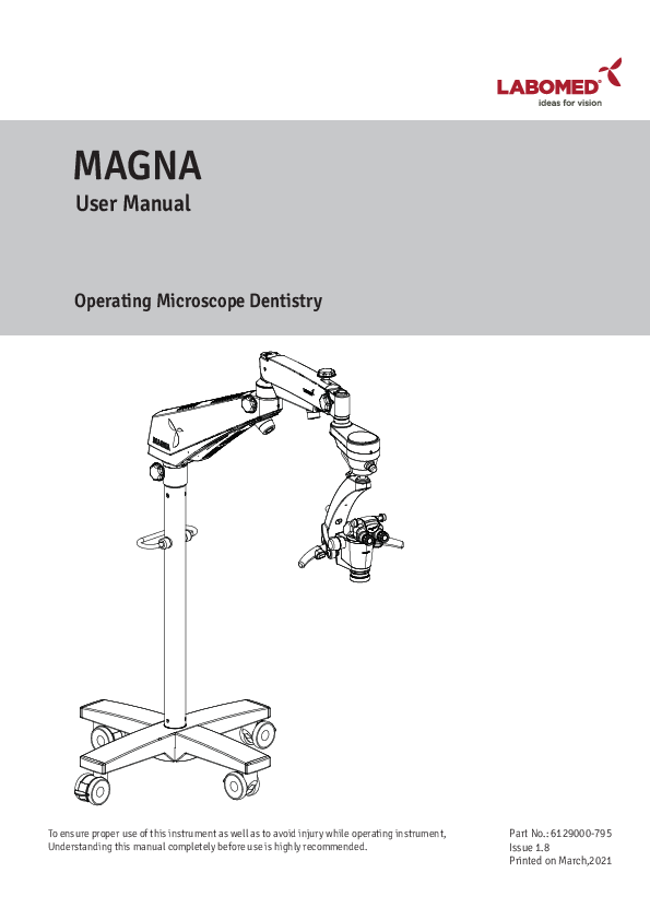
User Manual. Operating Microscope Dentistry. Part No.: 6129000-795. Issue 1.8. Printed on March,2021. To ensure proper use of this instrument as well as to ...
Extracted Text
MAGNA
User Manual
Operating Microscope Dentistry

To ensure proper use of this instrument as well as to avoid injury while operating instrument, Understanding this manual completely before use is highly recommended.

Part No.: 6129000-795 Issue 1.8 Printed on March,2021

MAGNA
MAGNA is a Trade name for LABOMED endodontics microscope. LABOMED is a registered trademark of Labo America, Inc. All other trademarks are the property of their respective owners. The information contained in this document was accurate at the time of publication. Specifications are subject to change without prior notice. LABOMED reserve the right to make changes to the product described in this user manual without notice and without incorporating those changes in any products already sold. ISO 13485 Certified - LABOMED products are designed and manufactured under quality processes that meet ISO 13485 requirements. No part of this publication may be reproduced, stored in a retrieval system, or transmitted in any form or by any means: electronic, mechanical, recording, or otherwise, without the prior written permission from LABOMED.

6129000-795

Magna

Issue 1.8 Printed on March,2021

LIST OF CONTENTS

1. 2. 3. 4. 5. 5A. 5B. 5C. 6. 7. 8. 8A. 8B. 9. 10. 11. 12. 13. 14. 14.1. 14.2. 14.3. 14.4. 15. 16. 17. 18. 19. 20. 21. 22. 23. 24. 25. 26. 27. 28. 29. 30. 31.

Introduction, Intended Use and Contraindications Product Description, Floor Stand Product Description, Ceiling Mount Installation References (Ceiling Mount) Ceiling Mount Installation Drop Ceiling Applications Leveling The Ceiling Mount System Installing Ceiling Mount On Concrete Ceilings Product Description, Wall Mount Wall Mount Installation Wall Mount Installation Procedure Wall Mount Installation on Wooden Wall Wall Mount Installation on Masonry Wall Construction Requirements (Ceiling / Wall Mount) Warning and Cautions Explanation of Symbols Standards and Directives Unpacking Installation of Cross Base (Mobile Stand) Installation of Microscope (Mobile Stand) Electrical Connections Wiring Coding Diagram Control Elements Using the Microscope Use of Accessories Thermal Cut-off Tension Adjustment Moving & Storage the Instrument Care and Maintenance Cleaning and Disinfection Autoclaving Schedule of Autoclavable Caps Ambient Requirement Disposal Technical Specification Troubleshooting Table Guidance Tables Dimensions and Weight Glossary Warranty

6129000-795

Magna

MAGNA
1 2 3 4 - 10
11 - 12 13 14 - 15 16 - 20 21 - 23
24 - 25 26 - 28 29 30 - 31 32 33 34 35 36 - 37 38 - 39 40 41 - 42 43 - 44 45 - 46 47 47 48 49- 50 51 51 52 53 53 54 55 - 56 57 - 60 61 62 63 - 64
Issue 1.8 Printed on March,2021

MAGNA
1. INTRODUCTION AND INTENDED USE

LABOMED Magna is a surgical and diagnostic microscope that is adaptable for different surgical needs for consistent visualization during all intra operative phases of endodontics by providing a magnified view of the surgical field without compromising performance.
The microscope provides extremely high optical image quality, good depth of focus, and a wide field of view for precise surgery. Illumination control and high eye point of the observation head helps reduce the user's work fatigue and allows comfortable use over a long period.
Salient features of this microscopes are:
1. The observation head can easily be positioned with the help of a suspension arm. 2. An advanced Galilean Zoom 1:6, also convertible to 8 step magnichanger allows optimal magnification
for various needs at different magnification levels. 3. Cold light illumination with a high intensity 50W LED lamp is provided using a fiber optic guide for
proper illumination. 4. An effortless articulation system ABA (Automatic Balancing Arm) features an electromagnetic brake system
that enables the ultimate flexibility in maneuvering the microscope's viewing angle and position. 5. The Labomed NuVar CMO with variable working distance comes as standard and provide greater
convenience to user in achieving a comfortable working distance. 6. The rigid Cross base with caster wheels provides stability and mobility to the device. 7. When the microscope is not in use, the suspension arm can be folded over the main body for compact storage.
INTENDED USE

The Magna microscope is an AC powered device intended for use during diagnosis and surgery to provide a magnified view of the region of interest. Note: Use Magna as specified in the intended use.

CONTRAINDICATIONS - NONE

CONFIGURATIONS Microscope
Magna Floor Stand (std arm) Magna Ceiling Mount (std arm) Magna Wall Mount (std arm) Magna Ceiling Mount (Heavy duty) long arm Magna Wall Mount long arm

Catalogue No. 6129100 6129200 6129300 6129201 6129301

Ceiling Mount Options (Heavy Type / 170 mm Dia)
Ceiling Height 10 Ft (305 cm) 12 Ft (366 cm)

Column Length (Microscope) 2.4 Ft (740 mm) 4.4 Ft (1350 mm)

6129000-795

Magna

1
Issue 1.8 Printed on March,2021

MAGNA
2. PRODUCT DESCRIPTION (FLOOR STAND)

18

17

16

19 20
14 15

21

23

12

13

6

9

25

10

11

28

8

5

22

26 27 7

24

4

2 3
1

Figure-1

1. Caster wheel with Brakes

16. Suspension Arm Hydraulic Movement Lock

2. Cross Base Top

17. Suspension Arm

3. Cross Base Bottom

18. Suspension Arm Spring Tension Adjustment

4. Column

19. Suspension Arm Movement Locking Knob

5. Handle for transport

20. Swivel Arm

6. Swivel Arm Locking Knob

21. 7 pin connector for ABA Arm

7. Common Main Objective with Fine Focusing

22. Left Hand Release (Electromagnetic Clutch)

8. Right hand Release (Electromagnetic Clutch)

23. Wire Mesh with Fibre light guide inside

9. Eyepieces

24. ABA Release Button

10. Ergo Head 0 - 210� adjustable

25. Filter Change knob

11. Zoom Magnification Knob

26. DBSI

12. 2 pin connector for Clutch Buttons

27. Rotoplate

13. Illumination Control Knob

28. Zoom to step changer button

14. ABA (Auto Balancing Arm) Electromagnetic Clutch

15. Auto Balancing Arm Locking Knob

6129000-795

Magna

2
Issue 1.8
Printed on March,2021

MAGNA
3. PRODUCT DESCRIPTION (CEILING MOUNT)
15
1

2

3 4

5
6 7
8

12
14 Figure-2

9 10
11
13

1. Column 2. Cover Mount (to be used in false ceiling only) 3. Swivel Arm 4. Suspension Arm 5. Suspension Arm Hydraulic Movement Lock Knob 6. Auto Balancing Arm Lock Knob 7. ABA (Auto Balancing Arm) Magnetic Clutch 8. Illumination Control knob 9. Ergo Head 0 - 210� adjustable 10. Eyepieces 11. Right Hand Release (Electromagnetic Clutch) 12. Zoom Magnification Knob

13. Common Main Objective with Fine Focusing 14. Left Hand Release (Electromagnetic Clutch) 15. Master Plate

6129000-795

Magna

3
Issue 1.8
Printed on March,2021

MAGNA
4. INSTALLATION REFERENCES (CEILING MOUNT)
CEILING MOUNT (Standard Arm)

741 (2.4")

CONCRETE ROOF

500

600

150

�250mm

3050 (10')

360�

310�
Ceiling Height = Column Length 3050mm = 741mm 3200mm = 891mm 3400mm = 1091mm 3600mm = 1291mm 3658mm = 1350mm
Formula = Deduct 2309mm from Ceiling height(mm) Balance will be Column Length.

220� 360�

1064 (3'6")

6129000-795

Figure-3
Magna

4
Issue 1.8 Printed on March,2021

INSTALLATION REFERENCES (CEILING MOUNT)
CEILING MOUNT SYSTEM FOR 12 FEET CEILING HEIGHT

MAGNA

500

1000

150

n 168

1351 (4.43')

3660 (12') 2309

1064

6129000-795

Figure-3(A)
Magna

5
Issue 1.8 Printed on March,2021

MAGNA
INSTALLATION REFERENCES (CEILING MOUNT)

CEILING MOUNT SYSTEM FOR 11 FEET CEILING HEIGHT

500

1000

150

1043 (3.42')

3352 (11') 2309

1064

6129000-795

Figure-4
Magna

6
Issue 1.8
Printed on March,2021

MAGNA
INSTALLATION REFERENCES (CEILING MOUNT)
CEILING MOUNT SYSTEM FOR 10 FEET CEILING HEIGHT

500

1000

150

n 168

741 (2.4')

3050 (10') 2309

1064

6129000-795

Figure-5
Magna

7
Issue 1.8 Printed on March,2021

INSTALLATION REFERENCES (CEILING MOUNT)

Marking References

175mm

175mm

MAGNA

175mm

175mm

400mm

175mm

175mm

175mm

175mm

400mm

MASTER PLATE Figure-6

Master Plate Spacer Ceiling Mount Column

�168MM

6129000-795

Figure-7
Magna

8
Issue 1.8 Printed on March,2021

MAGNA
INSTALLATION REFERENCES (CEILING MOUNT)

1385.3mm

R1800mm

694mm

6129000-795

1199mm
Figure-8

Operator Position. Patient is right below the microscope optical head.

Magna

9
Issue 1.8 Printed on March,2021

MAGNA
INSTALLATION REFERENCES (CEILING MOUNT)

694mm

1198mm

Operator Position. Patient is right below the microscope optical head.

6129000-795

Figure-9
Magna

10
Issue 1.8 Printed on March,2021

MAGNA
5. CEILING MOUNT INSTALLATION
5A. DROP CEILING APPLICATIONS
Many newer constructions use drop ceilings. Whenever this type of application is used, all supporting structure and electrical service (115/230 VAC, 15A ) is the customer's responsibility and must be completed before the installation.
WARNING: THE SUPPORTING STRUCTURE FOR THE CEILING MOUNT AND WALL MOUNT INSTALLATION MUST BE CAPABLE OF SUPPORTING A MINIMUM WEIGHT OF 600 LBS (272 kg) AND BE STABLE LATERALLY AND VERTICALLY, AND FREE FROM VIBRATION.
WARNING: � CEILING MOUNT PLATE AND COLUMN ASSEMBLY TOGETHER CAN WEIGHTS APPROXIMATELY UPTO 66LBS (30KG) WITH MICROSCOPE. � TO AVOID PERSONAL INJURY TWO (2) PEOPLE ARE REQUIRED FOR PROPER INSTALLATION.
PROCEDURE:
1. Ensure that there is a 350mm diameter hole in the drop ceiling to mount the master Ceiling plate. 2. Labomed Ceiling Mount system for wooden ceiling can be installed by fixing a flat wooden membrane at least 90mm thick to the joist and then mount the Master Ceiling Plate to the wooden membrane as shown in Fig.10 and Fig.-11. 3.Using the Paper template provided, mark the positions of the Eight (8) mounting holes on wooden
membrane refering figure. 4. Drill Eight (8) 1/4"(6mm) pilot holes either direct into Joist or the additional wooden membrane as per the roof available. 5. Place a 10mm flat washer over each of the Eight M10 X 100mm hex head lag screws. 6. Referring Flat side of Master Plate, line up the (6) holes with the pilot holes in the mounting surface and insert the hex head lag screws into the holes. 7. Tighten the master Plate with a 17mm Hex Socket Spanner. 8. Position and align the ceiling Mount against the master plate and insert 6 socket head bolts M12 X 40. 9. SlightlyTighten all the bolts using Allen key 10mm. 10. Use a level to ensure the column assembly is Levelled vertically. Refer Section "Leveling the ceiling Mount system" to correct any leveling concerns. 11. After levelling the column. Tighten all 6 bolts to the full torque. 12. Completing of all the procedure from 1 to 11 above is the responsibility of the customer. Labomed representative will complete rest of the microscope Installation after this. 13. Power up the system with the cable provided. Make sure AC outlet is hospital grade & grounded properly. 14. Put the drop ceiling tile back into place.

6129000-795

Magna

11
Issue 1.8 Printed on March,2021

Wooden membrane Joist
Master Plate Shim
Column

MAGNA

Level
Heavy Duty vibration free Ceiling Mount Figure-10

Wooden membrane

Joist

Master Plate Shim
Column

Level

6129000-795

Normal Ceiling Mount Figure-11

Magna

12
Issue 1.8 Printed on March,2021

MAGNA

5B. LEVELING THE CEILING MOUNT SYSTEM
It is important to ensure the column for the ceiling mount is Plumb after installation. The column must be perfectly vertical to prevent the microscope system from drifting from side to side.Use following procedure:
1. Use the 10mm Allen key to slightly loosen all of the (6)M10 bolts. 2. Place a level across the bottom of ceiling mount as shown in Figure and to check the Vertical leveling. Use Shims as required and adjust the RAWL Bolts/ Lag bolts until the column is Vertical. 3. Tighten all screws securely.
NOTICE:Shims and Shim materials are to be provided by the customer and are not furnished by Labomed. There are numerous shims and shim materials commercially available and no specific type or brand name is required.

Wooden membrane Joist
Master Plate Shim
Column

Wooden membrane

Joist
Master Plate Shim

Column

Level

Level

Heavy Duty vibration free Ceiling Mount Figure-13

6129000-795

Magna

Normal Ceiling Mount Figure-14
13
Issue 1.8 Printed on March,2021

MAGNA

5C. INSTALLING CEILING MOUNT ON CONCRETE CEILINGS

Fixing of Master Plate:

1. Use the Paper template provided to mark the position for the anchors of Master Plate.

2. Drill the Eight (8) mounting holes 14mm diameter and 100mm deep.

3. Place a 10mm flat washer and a split washer over each of the Eight M10 X 75 hex head RAWL Plug.

4. Referring flat surface of Master Plate, align 8 holes with the pilot holes in the ceiling.

5. Insert the hex head RAWL screws into the holes and fully tighten the Master Plate with a 17mm hex

socket spanner.

Installation of Ceiling Mount:

6. Position the ceiling Mount against the master plate and insert 6 socket head bolts M12 X 40

after aligning the 6 mounting holes.

7. Slightly tighten all the bolts using Allen key 10mm .

8. Use a level to ensure the column assembly is Leveled vertically. Refer Section "Leveling the ceiling

Mount system" to correct any leveling concerns.

9. Fully tighten all the bolts with 10mm allen key.

10. All the procedure from Part 1 to 9 above is the responsibility of the customer to organise. Labomed

representative will complete rest of the microscope Installation after this.

10. Power up the system with the cable provided. Make sure AC outlet is hospital grade & grounded

properly.

11. Put the drop ceiling tile back into place.

Concrete Ceiling

Concrete Ceiling

Master Plate Shim
Column

Master Plate Shim

Column

Level

Level

Heavy Duty vibration free Ceiling Mount Figure-15

6129000-795

Magna

Normal Ceiling Mount Figure-16
14
Issue 1.8 Printed on March,2021

MAGNA
INSTALLATION REFERENCES (CONCRETE CEILING MOUNT)
RAVAL PLUG M10x75mm SS-854 (8-NOS.) TO BE FIXED IN CONCRETE CEILING
BOLT M1Ox75mm SS-854 (8-NOS.) FIXED IN RAVAL PLUG SPRING LOCK WASHER 12MM SS-995 (6-NOS.)
BOLT M12x50mm SS-994 (6-NOS.)
SS-666 M4x10 PH. PAN HEAD SCREW (10-NOS.)

Figure-17

LIST OF CONTENTS:

� Rawl Plug with Cap (Ceiling- 6pcs./ Wall- 6pcs) - Part No. SS- 854

� Washers (Ceiling - 6pcs / Wall - 6pcs)

- Part No. 6134010 - 451

� Acrylic Plate

- Part No. 6129001 - 043

� Hole Mounting Template (Ceiling)

- Part No. 6129001 - 404

� Ceiling Mount Cover

- Part No. 6137200 - 014

� Column

- Part No. 6129001 - 117

� Hole Mounting Template (Wall)

- Part No. 6129002 - 403

� M4x12 Pan Head Screws for Acrylic Plate- 10 pcs - Part No. SS - 666

� Threaded Spacer - 12 pcs

- Part No. 6129001 - 122

� M10x40 Socket Head Cap Screw- 4pcs

- Part No. SS - 707

� M6x10 Socket Set Screw- 3pcs

- Part No. SS - 174

6129000-795

Magna

15
Issue 1.8 Printed on March,2021

MAGNA
6. PRODUCT DESCRIPTION (WALL MOUNT)

1 2
3

Figure-18
1. Wall Mount Bracket 2. Mount Shaft 3. Swivel Arm 4. Suspension Arm 5. Suspension Arm Hydraulic Movement Lock Knob 6. Auto Balancing Arm Lock Knob 7. ABA (Auto Balancing Arm) Magnetic Clutch 8. Illumination Control knob 9. Ergo Head 0 - 210� adjustable 10. Eyepieces 11. Right Hand Release (Electromagnetic Clutch) 12. Zoom Magnification Knob 13. Common Main Objective with Fine Focusing 14. Left Hand Release (Electromagnetic Clutch)

6129000-795

Magna

4 5 6 7 8

9

10

12

11

13

14

16
Issue 1.8 Printed on March,2021

MAGNA
INSTALLATION REFERENCES (WALL MOUNT)

6129000-795

Operator Position. Patient is right below the microscope optical head.

Figure-19
Magna

17
Issue 1.8 Printed on March,2021

MAGNA
INSTALLATION REFERENCES (WALL MOUNT)
Rotation of Horizontal Arm about the Column on the Wall Mount is limited with the wall acting as a stop.

6129000-795

Rotation of Suspension Arm about the Horizontal Arm on both the Ceiling Mount and the floor stand is 360�.

Figure-20
Magna

18
Issue 1.8 Printed on March,2021

INSTALLATION REFERENCES (WALL MOUNT)

Magna Wall Mount with short Arm

6-COUNTER HOLE �16mm x 2.0mm DEEP
THRU HOLE �11.0mm

406mm

346mm

500mm

750mm 600mm

150mm

MAGNA

125

125mm

�250mm

220�
360� 310�

2542mm 2242mm

2267mm

1063mm 1232mm

240� 360�

Magna Wall Mount with long Arm

6-COUNTER HOLE �16mm x 2.0mm DEEP
THRU HOLE �11.0mm

406mm

346mm

Figure-21
500mm

1150mm 1000mm

150mm

125

125mm

220�
360� 310�

�250mm

2542mm 2242mm

2267mm

1063mm 1232mm

6129000-795

Figure-22
Magna

19
Issue 1.8 Printed on March,2021

MAGNA
INSTALLATION REFERENCES (WALL MOUNT)
Wall mount: MARKING REFERENCE
Anchoring the Wall mount
Reference A Paper Template for marking B Wall Mount Assembly C Distance from Floor- Refer suitable height as per ordered configuration
from figure-21 or 22

6-COUNTER HOLE �16mm x 2.0mm DEEP
THRU HOLE �11.0mm

406mm

125mm

125mm

AB

C

6129000-795

Figure-23
Magna

20
Issue 1.8 Printed on March,2021

MAGNA
7. WALL MOUNT INSTALLATION
WALL MOUNT INSTALLATION
Before Initiating the installation of Labomed Wall Mount Microscopes, You must ensure that there is proper space available as per the configuration selected. Refer to Figure 21 and 22. Measure the distance between the centers of the studs. The Labomed Wall Mount Model is designed to mount directly on a wall with wood studs spaced 406mm (16") centers or on solid brick/concrete wall minimum 229mm (9") thick wall.
R25

25

125

300

250 �0.2

125

25

25

406 �0.2

456

LIST OF CONTENTS

Figure-24

1. Paper template for marking - 1 2. Wall Mount Assembly -1 3. Hexagonal Lag bolts (for wooden walls) -6 4. Plain Washer -6 5. RAWL Anchor Bolts (for Masonry walls) -6 6. Cap set bolt -6

25 6-THRU HOLE �12.0

6129000-795

Magna

21
Issue 1.8 Printed on March,2021

MAGNA
7A. WALL MOUNT INSTALLATION FOR WOODEN WALL

6-NOS HEX HEAD WOODEN SCREW ?10x100

6129000-795

6NOS-WASHER
Figure-25

CAP RAWAL PLUG M10 PART NO SS-855(6-NOS)

Magna

22
Issue 1.8 Printed on March,2021

MAGNA
7B. WALL MOUNT INSTALLATION FOR SOLID BRICK WALL

RAVAL PLUG M10x75mm SS-854 (6-NOS.) TO BE FIXED IN WALL

BOLT M1Ox75mm SS-854 (6-NOS.) FIXED IN RAVAL PLUG

6129000-795

WASHER (6-NOS.)

CAP RAVAL PLUG M10 SS-855 (6-NOS.)

Figure-26
Magna

23
Issue 1.8 Printed on March,2021

MAGNA
8. WALL MOUNT INSTALLATION PROCEDURE
8A.WALL MOUNT INSTALLATION ON STANDARD SIXTEEN INCH(16"406 MM) WOODEN WALL STUD SPACING
For securing the Wall Mount System to construction using wooden wall studs spaced on 16 (406 mm) Inch centers, it is recommended that 3/8" x 4" hex head lag screws are used.

Figure-27
WARNING: THE MOUNTING HARDWARE SUPPLIED FOR WOODEN WALL IS NOT DESIGNED FOR INSTALLATION TO WALL WITH STEEL STUDS OR TO CINDER BLOCK/MASONRY WALLS.

6129000-795

Magna

24
Issue 1.8 Printed on March,2021

MAGNA

8A.1. LEVELING THE WALL MOUNT PLATE ASSEMBLY
It is important to ensure that wall mount (6137100-806) is levelled both horizontally and vertically, after installation. Leveling of the wall mount assembly is necessary to prevent the microscope system from drifting from side to side when it is being used at full extension.

Wall Mount Assembly
Shim

Level

Figure-28
1. Slightly tighten the bolts on the top side- leaving the bottom bolts slightly loosened. 2. Place a level across the top of the back plate to check the horizontal leveling. See Figure 28 . 3. Use the 17mm socket and ratchet to slightly loosen the 3/8" x 4" hex head lag screws in the
corners of the back plate. 4. Adjust the back plate until it is level and tighten the three lag screws on the bottom leaving the
top lag screws loosened slightly. 5. Place a level vertically along the face of the wall Mount, on both sides, to ensure it is perpendic-
ular to the floor. See Figure above . 6. If the wall mount is not perpendicular, insert shim material between the wall mount and the wall
next to the lag screws Refer figure above. Check with the level and tighten the lag screws once the mount is level. 7. Check the other side and insert shims as needed and then tighten the lag screws. 8. When the Wall Mount is level, both horizontally and vertically, securely tighten all Six lag screws before installing microscope. 9. Levelling and Installing wall mount is customers responsibility. Labomed representative will complete rest of the microscope Installation after this.

6129000-795

Magna

25
Issue 1.8 Printed on March,2021

MAGNA
8B. WALL MOUNT INSTALLATION ON SOLID BRICK MASONRY WALL MINIMUM 9" THICK
For securing this Wall Mount Model to a Solid Brick wall, Use the Six(6) M10 X 75mm RAWL Anchor bolts provided. See Figure below.

Figure-29

1. Determine the desired location on the wall where the microscope is to be mounted. 2. Place the Paper template against the wall and fix with tape. Mark Six (6) holes ensuring template is straight. 3. Using a 16mm" masonry drill bit, drill Six (6) 16mm holes min 75mm deep in the wall spaced as Outlined above. 4. Use 10mm X 75mm long RAWL Anchor bolts. 5. Place the RAWL bolts through the holes and carefully insert the bolts into the wall. 6. Take out the threaded bolt. 7. Position the wall mount against the wall .Place flat washer under head of coach bolt and thread in the Six (6) RAWL bolts in the wall. 8. Using a 17mm socket and ratchet arrangement, tighten the Six (6) RAWL bolts securing the wall mount into position. Ensuring the wall mount (top edge and front face) is level. 9. Levelling and Installing wall mount is customers responsibility. Labomed representative will complete rest of the microscope Installation after this.

NOTICE: Shims and shim materials are to be provided by the customer and are not furnished by Labomed. There are numerous shims materials commercially available and no specific type or brand name is implied.

6129000-795

Magna

26
Issue 1.8 Printed on March,2021

Shim

Wall Mount Assembly

Level

MAGNA

6129000-795

Figure-30
Magna

27
Issue 1.8 Printed on March,2021

MAGNA
8B.1. LEVELING THE WALL MOUNT ON MASONRY WALL
1. Slightly tighten the bolts on the top side- leaving the bottom bolts slightly loosened. 2. Place a level across the top of the back plate to check the horizontal leveling. See figure-30. 3. Use a 17mm Socket & Ratchet arrangement to slightly loosen the Six (6) toggle bolts in the corners of the back plate. 4. Adjust the wall mount until it is level and tighten the three RAWL bolts on the bottom leaving the top toggle bolts loosened slightly. 5. Place a level vertically along the face of the back plate,on both sides, to ensure it is perpendicular to the floor. See figure-30. 6. If the back plate is not perpendicular, insert shim material between the back plate and the wall next to the RAWL bolts. Check with the level and tighten the toggle bolts once the mount is level. 7. Check the other side and insert shims as needed and then tighten the toggle bolts. See figure-30. 8. When the back plate is level, both horizontally and vertically, securely tighten all Six toggle bolts before installing microscope.
8.B.2. INSTALLING THE HORIZONTAL ARM ASSEMBLY
1. Open the microscope arm box and take out the arm. 2. Unscrew the threaded plug from wall mount shaft as shown in fig-30. 3. Assemble the Arm on wall mount shaft referring fig.3 and Reinstall the threaded plug into place. 4. Complete the rest of Installation as per fig.1,2,3 or 4 as ordered.
For further Installing & Use of the Microscope : Refer Section-10 Onwards.

6129000-795

Magna

28
Issue 1.8 Printed on March,2021

MAGNA
9. CONSTRUCTION REQUIREMENTS (CEILING/WALL Mount)
1. The Magna ceiling mount/wall mount must be installed as per detailed in this manual. 2. The construction specialist must confirm in writing that the applicable regional and local codes & regulation have been
complied with and that the points listed below have been observed. The customer must keep this confirmation with his records on the ceiling mount. A copy of this document must be enclosed by the customer with his record. 3. The roof on which ceiling mount is to be mounted must have the following load capacity: Perpendicular force: minimum 1500 Nm Torque: Perpendicular to the Ceiling 1500 Nm minimum.
Parallel to the Ceiling 1200 Nm minimum. Also take into account any additional loads acting on the Ceiling and any other loads anchored in the Ceiling. The Ceiling should preferably be made of minimum 8 inches concrete. 4. The Master Plate should be installed at the time of Construction. 5. Minimum edge distance required on all sides is 16". 6. The ceiling plate must be aligned in a parallel position (max. deviation �1�).
The following must be taken into consideration when calculating the effective strength: � Specification of the bolt / anchor manufacture. � Quality of the structural roof, e.g. the strengths and the thickness of the concrete. � Spacing of anchor holes and weakening effect of anchor holes in the ceiling.
NOTE: If an existing ceiling mount is ever exchanged, never re-use the old anchors. New anchor holes must be drilled. When Calculating the effective strength of the new anchors, make sure to take into account the weakening effect of the old holes in the ceiling. On the basis of the above aspects, the person responsible for the building must decide on and take responsibility for the most suitable method of anchoring.
The weight of the mount including the surgical microscope is as follows: � Ceiling mount kit: Approx..........30kg. � Surgical microscope (Swivel Arm & Suspension Arm): Approx......28kg. � Microscope Carrier: Approx...................10kg. � Total Magna: Approx........70kg.
Control and Power Supply of the System Power line: 3/1.5mm2 Fuse: 4.0Amp. Power consumption: 200W
NOTE: A socket with properly installed protective earth connection must be provided at the installation site near the Ceiling flange. The terminals for power connections are located on the ceiling mount. Potential equalization: take the necessary action in the building to include the instrument in the protective measures of "potential equalization".

6129000-795

Magna

29
Issue 1.8 Printed on March,2021

MAGNA
10. WARNINGS AND CAUTIONS

LABOMED is not responsible for the safety and reliability of this instrument when: - Assembly, disassembly, repair, or modification is made by unauthorized dealers or persons. - The instrument is not used in accordance with this user manual.

A WARNING is an instruction that draws attention to the risk of injury or death.

WARNING: USERS OF THIS EQUIPMENT SHOULD BE THROUGHLY TRAINED IN THE APPROPRIATE MEDICAL PROCEDURES. FURTHERMORE, THEY SHOULD TAKE THE TIME TO READ AND UNDERSTAND THESE INSTRUCTIONS BEFORE PERFORMANCE ANY PROCEDURE. THEY SHOULD ALSO READ AND UNDERSTAND THE INSTRUCTIONS FOR ANY OTHER EQUIPMENT USED IN CONJUNCTION WITH THIS MICROSCOPE (i.e. ELECTRO SURGICAL GENERATORS). FAILURE TO DO SO MAY RESULT IN INJURY TO THE PATIENT AND/OR DAMAGE TO THE MICROSCOPE.

WARNING: THIS INSTRUMENT SHOULD BE USED IN STRICT ACCORDANCE WITH THE INSTRUCTIONS OUTLINES IN THIS USER'S GUIDE. THE SAFETY OF THE OPERATOR AND THE PERFORMANCE OF THE INSTRUMENT CANNOT BE GUARANTEED IF USED IN A MANNER NOT SPECIFIED BY LABOMED.

WARNING: DO NOT REPAIR OR SERVICE THIS INSTRUMENT WITHOUT AUTHORIZATION FROM LABOMED. ANY REPAIR OR SERVICE TO THIS INSTRUMENT MUST BE PERFORMED BY EXPERIENCED PERSONAL OR DEALERS TRAINED BY LABOMED OTHERWISE SERIOUS INJURY TO THE OPERATOR OR PATIENT MAY OCCUR.

WARNING: ANY MODIFICATION TO THIS UNIT MUST BE AUTHORIZED BY LABOMED OTHERWISE SERIOUS INJURY TO THE OPERATOR OR PATIENT MAY OCCUR.

WARNING: IF THIS INSTRUMENT IS MODIFIED, APPROPRIATE INSPECTION AND TESTING MUST BE CONDUCTED TO ENSURE CONTINUED SAFE USE OF THIS INSTRUMENT.

WARNING: TO AVOID RISK OF ELECTRIC SHOCK, THIS EQUIPMENT MUST ONLY BE CONNECTED TO A SUPPLY MAIN WITH PROTECTIVE EARTH OTHERWISE DAMAGE TO THIS INSTRUMENT AND/OR INJURY TO THE OPERATOR OR PATIENT MAY OCCUR.

WARNING: ENSURE THAT THE VOLTAGE APPLIED TO THE UNIT IS THE SAME AS INDICATED ON THE DATA PLATE OTHERWISE DAMAGE TO THE UNIT MAY OCCUR.

WARNING: TO USE IN FLUCTUATION VOLTAGE ENVIRONMENT, CONSTANT VOLTAGE STABILIZER IS RECOMMENDED FOR SAFE & EFFICIENT USE OF DEVICE.

WARNING: THIS INSTRUMENT MUST BE PLUGGED INTO AN OUTLET WITH AN EARTH GROUND. DO NOT REMOVE OR DEFEAT THE EARTH GROUND CONNECTION ON POWER INPUT CONNECTOR OR THE UNIT'S POWER CORD OF THIS INSTRUMENT. DAMAGE TO IT MAY CAUSE INJURY TO OPERATOR OR PATIENT.

WARNING: THE EQUIPMENT OR SYSTEM SHOULD NOT BE USED ADJACENT TO OR STACKED WITH OTHER EQUIPMENT AND THAT IF ADJACENT OR STACKED USE IS NECESSARY, THE EQUIPMENT SHOULD BE OBSERVED TO VERIFY NORMAL OPERATION IN SUCH CONFIGURATION.

WARNING: THIS INSTRUMENT IS NOT SUITABLE FOR USE IN THE PRESENCE OF FLAMMABLE ANESTHETIC MIXTURES, SUCH AS OXYGEN OR NITROUS OXIDE.

WARNING: LED RADIATION - DO NOT STARE DIRECTLY INTO THE BEAM WHEN THE MICROSCOPE IS IN THE ON POSITION. INSTRUMENT IS PASSES IN RISK GROUP 2 PER IEC62471. (BLUE LIGHT HAZARDS).

WARNING: THE USE OF ACCESSORIES OR CABLES OTHER THAN THOSE SPECIFIED, BY LABOMED AND OTHER UNAUTHORIZED REPLACEMENT PARTS FOR THE INTERNAL COMPONENTS, MAY RESULT IN INCREASED EMISSIONS OR DECREASED IMMUNITY OF THE EQUIPMENT.

30

6129000-795

Magna

Issue 1.8 Printed on March,2021

MAGNA
WARNINGS AND CAUTIONS
A CAUTION is an instruction that draws attention to the risk of damage to the product.
CAUTION: THE INTERNAL CIRCUITRY OF THE INSTRUMENT CONTAIN ELECTROSTATIC SENSITIVE DEVICES (ESD) THAT MAY BE SENSITIVE TO STATIC CHARGES PRODUCED BY THE HUMAN BODY. DO NOT REMOVE THE COVERS WITHOUT TAKING PROPER ESD PRECAUTIONS.
CAUTION: DO NOT USE SOLVENTS OR STRONG CLEANING SOLUTIONS ON ANY PART OF THIS INSTRUMENT, AS DAMAGE TO THE UNIT MAY OCCUR SEE THE CARE AND MAINTENANCE SECTION FOR DETAILED CLEANING INSTRUCTIONS.
CAUTION: MEDICAL ELECTRONIC EQUIPMENT NEEDS SPECIAL PRECAUTIONS WITH RESPECT TO ELECTROMAGNETIC CHARGE (EMC) AND NEEDS TO BE INSTALLED AND SERVICED ACCORDING TO THE EMC INFORMATION PROVIDED IN THE ACCOMPANYING DOCUMENTS.
CAUTION: PORTABLE AND MOBILE RF COMMUNICATIONS EQUIPMENT CAN AFFECT MEDICAL ELECTRICAL EQUIPMENT.
CAUTION: THIS INSTRUMENT IS NOT TO BE USED NEAR HIGH-FREQUENCY EMITTING SURGICAL EQUIPMENT.
CAUTION: DO NOT CONNECT ANY EQUIPMENT TO THE DEVICE OTHER THAN THOSE INTENDED FOR USE WITH THE DEVICE.
CAUTION: DO NOT USE A CONVERTER ADAPTER THAT WILL CONVERT THE THREE-PRONG AC PLUG TO A TWO-PRONG LINE PLUG, THE POWER SUPPLY IN THIS MICROSCOPE WILL NOT BE PROPERLY GROUNDED, AND ELECTRIC SHOCK MAY RESULT.
CAUTION: REMOVE THE AC POWER PLUG FROM THE WALL SOCKET WHILE CHECKING FOR A BLOWN FUSE.
CAUTION: DO NOT ROLL THE MICROSCOPE OVER CABLES OR HOLES.
CAUTION: DO NOT REMOVE FERRITE BEADS IF APPLIED TO CABLES.
CAUTION: THE EMISSIONS CHARACTERISTICS OF THE EQUIPMENT MAKE IT SUITABLE FOR USE IN INDUSTRIAL AREA AND HOSPITALS (CISPR 11, CLASS A). IF IT USED IN RESIDENTIAL ENVIRONMENT (FOR WHICH CISP 11, CLASS B IS NORMALLY REQUIRED). THIS EQUIPMENT MIGHT NOT OFFER ADEQUATE PROTECTION TO RADIO FREQUENCY COMMUNICATION SERVICES. THE USER MIGHT NEED TO TAKE MITIGATION MEASURES, SUCH AS RE-LOCATING OR RE-ORIENTING THE EQUIPMENT.

6129000-795

Magna

31
Issue 1.8 Printed on March,2021

MAGNA
11. EXPLANATION OF SYMBOLS
Warning: Observe all warning labels and notes! If any label in missing on your instrument or has become illegible, please contact the manufacturer to obtain new labels. Caution label: Observe all caution notes to avoid any unwanted situation with the instrument. Brightness Control: After the illumination has been switched on, the user can continuously adjust brightness by turning the knob appropriately. Accompanying documents must be consulted. Compliance to medical devices directive 93/42/EEC and MDR 2017/745. Suspension Arm Locking. This way up � indicates the correct upright position of the transport package. Keep dry � the transport package shall be kept away from rain. Year of manufacture used on product data plate. Fragile- content of the transport package are fragile and should be handled with care. Electromagnetic interference can occur in the vicinity of devices carrying this symbol. Alternate current. Recycling of packaging materials. Tension Adjustment. Separate disposal of waste electrical equipment. Unsafe for use with MR (Magnetic Resonance). Do not over balance more than 5�. For ABA (Auto Balancing Arm) Power.

6129000-795

Magna

32
Issue 1.8 Printed on March,2021

MAGNA
12. STANDARDS AND DIRECTIVES
The instrument described in this user manual has been designed in compliance with the following standards:
� ISO 8600-3 First edition 1997-07-01 AMENDMENT 1 Optics and Optical instruments-Medical endoscopes and endoscopic accessories Part 3: Determination of field of view and direction of view of endoscopes with optics.
� ISO 8600-5 First edition 2005-03-15 Optics and photonics-Medical endoscopes and endotherapy devices Part 5: Determination of optical resolution of rigid endoscopes with optics.
� ISO 9001/13485 and USFDA 21 CFR 820 Quality management systems approved by UL. � ISO 14971 Risk management to medical devices.
DIRECTIVE USED
� MDR 2017/745 Annex IX and Rule B � Directives 93/42/EEC, Articles II, Section 5, Annex VII. � IEC 60601-1-3.1 edition (2012) � IEC 60601-1-2-4th edition (2014) � EN 55011:2016
CLASSIFICATIONS
� For Europe, per MDR 2017/745, the unit is a Class I instrument, per rule 13, Annex IX. � For the United States, the FDA classification is Class I. � Please observe all applicable accident prevention regulations.

6129000-795

Magna

33
Issue 1.8 Printed on March,2021

13. UNPACKING

MAGNA

The appliance is delivered in sub-assembled modular groups along with one Installation Kit and one user manual. Please check for the following when unpacking the device: 1. Mobile Cross base in two parts with brakes on caster wheels or Ceiling Mount or Wall Mount as ordered. 2. Column, depending on the type of mount ordered (Floor or Wall/Ceiling). 3. Swivel arm and suspension arm assembly with fiber optic cable. Depending upon type of mounting (Floor
or Wall/Ceiling). 4. Auto Balancing Arm (ABA) with magnichanger assembly and NuVar CMO with Variable focal length. 5. Observation head Ergo tiltable 0-210�. 6. DBSI (Double Beam Splitter Inclined), Double Iris Diaphragm, Rotoplate. 7. DSLR Adapter with Mount for Sony or Canon or Nikon as ordered. 8. Pair of eyepieces as ordered. 9. Power cord. 10. Installation Kit
a. Allen wrench 5 mm b. Allen wrench 8 mm 11. User manual
12. Paper template for location marking. (In case of Ceiling mount / wall mount only)

6129000-795

Magna

34
Issue 1.8 Printed on March,2021

MAGNA
14. INSTALLATION OF CROSS BASE (MOBILE STAND)

1. Open the box containing Cross Base Bottom as shown in Fig. 1.
2. Take out the Cross bottom base and put it on floor as shown in Fig. 2.
3. Open the Box containing Cross Base Top as shown in Fig. 3.

Fig. 1 Fig. 2

4. Take out the Cross Base Top and put iron floor as shown in Fig. 4.
5. Referring Fig. 5. Align the Cross Base Top on Cross Base Bottom by aligning the guide pins in guide holes and Tighten the 4 screws provided.
6. Assembled Cross Base will look like as shown in. Fig. 6.

Fig. 3 Fig. 4 Fig. 5 Fig. 6

6129000-795

Magna

35
Issue 1.8 Printed on March,2021

MAGNA
14.1 INSTALLATION OF MICROSCOPE (MOBILE STAND)

1. Open the microscope box. Take out (column) from the box. Mount the column onto a shaft in shaft in base by aligning the Corresponding holes in Column (A) and shaft (B). Secure it with (3) M6x16mm Allen Screws (C) using 4mm Allen Key as shown in fig.-7.
2. Take out the Arm Assembly from the same box and follow the Instruction below:
a. Ensure that the swivel arm lock knob (D) is loosened. b. Mount the Arm Assembly into Shaft (F). c. Align three holes (E) with tapped hole on Shaft (F). d. Use Allen Wrench 4mm and tighten 2 M6x16mm Allen
screws (G).

A C
B Fig. 7

E

G

D

F

3. Open another box and take out the carrier assembly from its packaging following arm as shown in fig.-8.
a. Insert the Auto Balancing Arm (ABA) shaft (H) into the suspension arm as shown in fig.-8 .
b. Lock the auto Balancing Arm (ABA) with the threaded Knob (I) as shown in fig.- 8.
c. Make sure the safety screw (1) is installed and tightened at position (2) so the coupling does not detach if knob (I) is accidentally unscrewed.
2

Fig. 7(a) I H
1

6129000-795

Magna

Fig. 8
36
Issue 1.8 Printed on March,2021

MAGNA
INSTALLATION OF MICROSCOPE (MOBILE STAND)

4. Install the standard accessories onto the carrier assembly as mentioned below: O

a. Loosen the M4 grub screw (3) by 2mm allen key and Fix Double

N

iris diaphragm (J) on magnichanger by re-tightening the m4 grub

screw.

b. Loosen the M4 grub screw (4) by 2mm allen key on Double Iris

Diaphragm and fix DBSi (Double beam splitter inclined) (K) and

M

re-tighten the M4 grub screw.

c. Remove the End cap from DBSi by rotating the ring (5) in Anticlock-

wise and fix DSLR Camera adapter (L) by matching the slot and rotate the ring (5) clockwise to tighten the same. Loosen the knob

K

(6) on DSLR adapter and fix the supplied Mount (Canon, Nikon,

J

Sony (L.1). Retighten the Knob (6) to secure C-mount.

d. Loosen the M4 grub screw in DBSi by 2mm allen key and fix the

Rotoplate (M). Re tighten the M4 grub screw.

e. Loosen the M4 grub screw by 2mm allen key on Rotoplate and

Fix Ergo Head (0� - 210� tiltable) (N) and retighten the M4 grub

screw.

f. Set both eyepieces to (O) dioptre on ergo head.

Note: Please ensure the accessories are fixed properly to have better visual results.

5. Mount the light guide by completing the steps below:

a. Switch off the illumination system.

The light guide comes pre-routed through the swivel arm (which

houses the LED illumination system, the suspension arm and

through the cable cover.

b. A wire mesh for Cable routing is Permanently fixed to carrier arm

at point (P).

c. Fold and gather wire mesh at Point (P) with one hand and Insert

P

the Fibre light guide into mesh with other hand.

d. Now release the wire mesh and Fasten its other end to cable cover

at point (H). Referring Fig.14.

e. Make sure the light guide has been routed through wire mesh into

the carrier system such that the microscope is not obstructed and

can be moved in its entire range of movement without stretching,

Kinking, or twisting the light guide.

6 L.1 5
L 4

Fig. 9 Fig. 9

3

Fig. 10

6129000-795

Magna

37
Issue 1.8 Printed on March,2021

14.2 ELECTRICAL CONNECTIONS

Connect the power cable to the AC inlet socket (1) located at the back of the swivel arm as shown in Fig. 11.
Switch on the power using the ON/OFF switch (2).
Note: The power supply is designed with universal input 100V-240V AC, 50/60Hz. To plug in the power supply, follow the instruction on the product label (3) located at the bottom of the arm as shown in fig.- 11.
1. REPLACING THE ILLUMINATION SOURCE
a. Remove the swivel arm covers by unscrewing the screws in top and bottom as shown in Fig. 12.
b. Remove the connections on the power supply and replace the illumination assembly (A) in Fig. 12 with a new assembly and refix the connections.
c. Assemble back the arm covers.
2. REPLACING THE FUSE
a. Locate the fuse at the AC inlet (B) as shown in Fig.13.
b. Use a flat head screw driver to open the fuse compartment (C). Two fuses are provided: one is a live fuse and the second is a spare fuse.
c. Replace the blown fuse with the spare fuse and close the fuse compartment.
Note: For proper ratings of Fuse used in microscope, refer to the label shown in fig.- 11.

2 1
A
B

Fig. 11 Fig. 12

Fig. 13

MAGNA 3
C

6129000-795

Magna

38
Issue 1.8 Printed on March,2021

ELECTRICAL CONNECTIONS
H ED
3. AUTO BALANCING ARM CONNECTIONS
a. Connect the 7 pin connector (D) at the 7 Pin female inlet (E) located in Suspension Arm for power in Auto Balancing Arm (ABA) as shown in Fig. 14.
b. Take the power wire having 2 pin connectors on both sides and connect to the 2 pin inlet (F) located on Auto Balancing Arm (ABA) and connect the other end of wire to point as marked ( ) on Auto Balancing Arm (ABA) to Power up the ABA system.

MAGNA
G F

4. LABEL DETAILS

1. Device Name

2. Model No.

1

3. Serial No.

4. Input Voltage

2

5. Frequency

3

6. Max. Load

7. Separate Disposal Waste

4

Electric Device

5

8. Manufacture

6

9. Company Trademark

10. Label Control No.

11. Fuse rating

12. IEC60601-1:2012 Labeling for Canada

7

13. IEC60601-1:2012 Labeling for

USA and Europe

14. Accompanying Document

Must be consulted

Fig. 14

14
13 12

11

8

10 9

6129000-795

Magna

39
Issue 1.8 Printed on March,2021

MAGNA
14.3 WIRING CODING DIAGRAM
Power Supply LA

6129000-795

Magna

40
Issue 1.8 Printed on March,2021

MAGNA
14.4 CONTROL ELEMENTS

1. ON / OFF SWITCH

The ON/OFF switch (A) is located at the back of the swivel arm. In

A

the ON position, a green LED (B) glows, and the cooling fan starts

running as shown in Fig. 15.

Set the intensity control knob (C) at the minimum intensity level before switching the system on as shown in Fig. 15.

To preserve the life of the LED, turn off the instrument when the microscope is not in use.

C
B Fig. 15

2. LIGHT INTENSITY CONTROL KNOB
The Light Intensity Control knob (D) is located at the front of the Auto Balancing Arm (ARM). The brightness of the field of view can be adjusted as desired using the intensity control knob as shown in Fig. 15(a).
3. AUTO BALANCING ARM (ABA) CONTROLS
a. Articulation of Auto Balancing Arm (ABA) can be handled through two clutch release buttons located on left side (E) and right side (F) of carrier arm as shown in Fig. 16.
b. Pressing and holding down of the clutch button can articulate the Auto Balancing Arm (ABA) in any of the desired position. Release of clutch button can lock the Auto Balancing Arm in the desired position.
4. FILTER CHANGE KNOB
Refer Fig. 16(a) Filter change lever is located in backside of Magnichanger Housing. Use lever H to change Filter Position.

6129000-795

Magna

D Fig. 15(a)

E

F

Fig. 16

H
Fig. 16(a)
41
Issue 1.8 Printed on March,2021

CONTROL ELEMENTS

4. LOCKING KNOBS

a. Swivel Arm Locking Knob

This knob shown as (G) locks the movement of the Swivel

arm at the desired position by turning it Clockwise as sho-

wn in Fig. 17.

H

b. Suspension Arm Locking Knob This knob shown as (H) locks the movement of the Suspension arm at the desired position by turning it clockwise as shown in Fig. 17.

c. Suspension Up/Down Movement Locking Knob This knob shown as (I) locks the up/down movement of the Suspension arm at the desired height by turning it clockwise as shown in Fig. 17.

d. Auto Balancing Arm (ABA) Carrier Locking Knob This knob shown as (J) locks the rotation of Auto Balancing Arm (ABA) at the desired position by turning it clock wise as shown in Fig. 17.

5. BRAKES

Lock the stand to prevent unwanted movement by pressing down all the four brakes (K) provided in the caster wheels and lift up the brakes to release the brakes as shown in Fig. 18.

6. LED FEATURES

Single Chip White LED with over 2250 white Lumen's. Large monolithic chip with uniform emitting area of 9mm. Lumen maintenance of greater than 70% after 60000 hrs. Current driven LED with variable drive current less than 1Amp through 13.5 Amp. Environment friendly ROHS compliant. Typical spectrum is 400 - 700 nm.

MAGNA I
J
G
Fig. 17
K
Fig. 18

6129000-795

Magna

42
Issue 1.8 Printed on March,2021

MAGNA
15. USING THE MICROSCOPE

WARNING: INSTRUMENT IS UNSAFE FOR MRI ENVIRONMENTS.

CAUTION:
Upon Installation, ABA System may feel stuck due to longtime Inoperative in transit or storage. This temporary mild locking may happen due to material Property of ABA braking Material. To overcome this situation,-Switch on the microscope, Press Push Button with one hand and Push ABA System with other hand to dislodge this temporary Air lock. Repeat it 7-8 times, ABA System will start working normally.

SETTING UP THE MICROSCOPE:

a. For stability of microscope, lock all four brakes on the

base caster wheels.

b. Optimize the Auto Balancing Arm (ABA) position by using

clutch motions shown as (A) and (A.1) to get the proper

field of vision as shown in Fig. 19.

A

c. Desired working distance can be obtained by rotating

the ring shown as (B) on the variable objective lens.

Fine focusing can be done by the same ring as

shown in Fig. 19.

d. After focusing, lock swivel arm, suspension arm and ABA

arm movements using lock knobs shown as (C) in Fig. 19.

e. Adjust the inter- pupillary distance (IPD) of the eyepieces

using the IPD adjustment knob shown as (D) in Fig.

19.

f. The illumination is controlled through the intensity control

knob shown as (E). Rotate it clockwise or anticlockwise

to achieve the desired illumination level as shown in

Fig. 19.

SETTING UP THE MAGNIFICATION:

a. Use the knobs (F) Fig 20 provided on the Magnichanger to select the desired magnification level.

b. Rotate these clockwise to increase and Anticlockwise to

K

decrease the level of magnification.

C E
D

Fig. 19

A.1 B

E

G

F

Fig. 20

6129000-795

Magna

43
Issue 1.8 Printed on March,2021

MAGNA
USING THE MICROSCOPE

CONVERSION FROM CONTINUOUS ZOOM TO STEP MAGNIFICATION:

a. Refer Fig. 20 Pressing the Red click button (G) located besides the Magnification indicator will select the 8 step magnification. Pressing the same Red click button from reverse side to select the maginification in continuous zoom.
b. Rotate the fine focusing ring shown as (A) Fig 21 to achieve fine focus.
c. Refer Fig 19 Use the Clutch Buttons shown as (A)on Left handle and (A.1) on Right handle to Centre the area of interest in the field of view.

Main Microscope Configuration:

Magna comes with standard accessories mentioned below:

a. NuVar variable objective, focal length 300-400mm

(standard).

b. 0�- 210� tiltable ergo binocular tube.

c. DBSi (Double beam splitter inclined).

d. Double iris diaphragm.

e. Rotoplate (0�- 20� of angle rotation).

C

f. DSLR adapter & Mount for Canon, Nikon, Sony.

Standard configurations include eyepieces with a magnification factor of 10x (12.5x eyepieces are optical).

B
E F
D
A.1 A Fig. 21

6129000-795

Magna

44
Issue 1.8 Printed on March,2021

16. USE OF ACCESSORIES
Model: Magna
MASTER PLATE 6129004-051

MAGNA

RETICULE

RETICULE

WALL MOUNT 6129002-805

MONITOR ARM 6129001-876
CEILING MOUNT 6129001-801

CEILING MOUNT 6129001-841

10X EYE PIECE 6129010

12.5X EYE PIECE 6129012

MONITOR ARM 6129004-810

TILTABLE ERGO HEAD (0-210�) 6122015

ARM ASSEMBLY WALL & CEILING MOUNT 6129001-804
ARM ASSEMBLY FLOOR MOUNT 6129000-850

DSLR ADAPTER 6134131

ROTO PLATE 6134115-801
DBSI 6134160

DOUBLE IRIS 6214051

CCD ATTACHMENT 6134110

MONITOR ARM 6129000-877

MICROSCOPE WITH ABA ARM ASSEMBLY 6129000-851
NUVAR CMO 6129000-824

STAND ASSEMBLY 6129000-813

LENS PROTECTER 6129000-875
Fig. 22

6129000-795

Magna

LASER FILTER
45
Issue 1.8 Printed on March,2021

MAGNA
USE OF ACCESSORIES
1. Rotoplate: Rotoplate eliminates neck craning, making it comfortable to view hard to see region of mouth from 9 and 3'O clock seated position.
2. DBSi (Double Beam Splitter Inclined): A beam splitter divides the light into two beams, it can be 50:50 or 80:20. In case of 80:20 ratio, 80% of light goes to observation head and 20% of light goes to camera accessories.
3. Double Iris attachment: An adjustable diaphragm attachment installed between Magnichanger and observation head or DBSi. It reduces incoming light and increases depth of field, it is very helpful for Photographic imaging.
The following adapters can be attached to DBSi (Double Beam Splitter inclined) as per user requirement.
a. DSLR camera adapter for Nikon, Canon and Sony cameras. b. CCD camera adapter for Mintron camera. c. Adapter for Sony Handy cam. d. Assistoscope for assistant viewing.
Attach the accessory to the left or right side of the beam splitter.

6129000-795

Magna

46
Issue 1.8
Printed on March,2021

MAGNA
17. THERMAL CUT-OFF
The instrument is designed with safety provisions. Fans in the electrical box provide free- and forced- air circulation to cool the electronic components. The instruments also includes a built-in-safety mechanism called "auto thermal cut-off". This mechanism is activated through Thermistors when the LED temperature rises above 80�C. This time Thermistor sensor activates and provide resistance to circuit inflow. This causes LED light blinking as an indicator of high LED temperature. Allow the LED to cool down before switching it on again.

18. TENSION ADJUSTMENT
If any optional accessories are added to the microscope, suspension arm tension must be adjusted to compensate for the additional weight.
1. Tension Adjustment for Floor Mount
a. Refer Fig.23 Use an 8mm allen wrench in bolt (A) . Rotate it clockwise to increase the tension as desired. Rotate it counterclockwise to decrease the tension as desired.
2. Tension Adjustment for Ceiling / Wall Mount
a. Refer Fig.24 Use an 8mm Box Spanner (LK-008 BS) with long handle provided with microscope in bolt (B) . Rotate it clockwise to increase the tension as desired. Rotate it counter clockwise to decrease the tension as desired.

MAGNA
A Fig. 23
B

Fig. 24

6129000-795

Magna

47
Issue 1.8 Printed on March,2021

MAGNA
19. MOVING & STORAGE THE INSTRUMENT

Fold the system as shown before moving & during storage

Fig. 25
MOVING THE STAND
1. Turn off the unit at the power switch. 2. Disconnect the power cable. 3. Remove the video cable from the video modules (e.g., video monitor, USB monitor) and the camera control
unit. 4. Release the brakes. 5. Be careful when passing through doorways to avoid collisions of any kind. Do not move the instrument
over steps or cables as the stand can topple. Be extremely careful when moving the instrument over slopes. Do not park the instrument on a slope.

6129000-795

Magna

48
Issue 1.8
Printed on March,2021

MAGNA
20. CARE AND MAINTENANCE
This instrument is a high grade technological product and does not require any special periodical Maintenance if handled carefully. Still to ensure optimum performance and safe working order of the instrument, it's safe functioning must be checked periodically as per table below. We recommend having this check performance by our service representative as part of regular maintenance work. If a failure occurs which you cannot correct using the trouble- shooting table, attach a sign to the instrument stating out of order and contact our service representative for servicing part or circuit diagram etc.
Surgical Microscope Maintenance / Service Check

6129000-795

Magna

49
Issue 1.8 Printed on March,2021

MAGNA
CARE AND MAINTENANCE
CARE INSTRUCTIONS
1. Keep accessories away from dust when not in use, e.g. protect them with dust cover. 2. Remove dust with a pneumatic rubber blower and soft brush. 3. Protect your microscope from moisture, fumes, acids and cosmetic materials. Do not store chemical
close to the instrument. 4. Protect it from improper handling. Never install other devices sockets or unscrew optical system
and mechanical parts unless explicitly instructed to do so in this manual. 5. Protect the microscope from oil and grease. Never oil or grease the guide surfaces or mechanical
parts. 6. Remove coarse contamination using a damp disposable cloth. 7. Use disinfectants refered as in section 21 (cleaning & disinfection) of this user guide. 8. Use special optics cleaning cloths and pure alcohol for cleaning lenses and eyepieces. 9. Clean optical components using a lint-free cloth. Soak the cloth using a little methanol or Glass cleaner.
Do not use ethanol and spirit. 10. LABOMED Max Lite coating are fungal resistant. If you clean as described above, the coatings
will not be damaged. 11. If cleaning and disinfection is done as described insection 21 is no impact of multiple cleaning/
Disinfection on mechanical and optical parts. Paints & Coating are rigid and life long.
TROPICAL ENVIRONMENT / FUNGUS
LABOMED employs certain safety precaution in its manufacturing techniques and materials. Other preventive measures include: � Keep optical parts clean. � Use and store them in a clean, cool and dry environment only. � Keep moisture away using silica gel and dust cover.
OCCUPATIONAL SAFETY AND HEALTH PROTECTION
� Observe work safety and health protection of persons responsible for processing contaminated products. � Current regulations of hospital hygiene and prevention of infection must be observed in the prepara-
tion, cleaning and disinfection of the products.
INSTRUCTIONS WORKPLACE
� Remove surface contamination with a paper towel.

6129000-795

Magna

50
Issue 1.8 Printed on March,2021

MAGNA
21. CLEANING AND DISINFECTION
Following disinfectants are recommended for cleaning and disinfection.
1. Normal household bleach (Sodium hypochlorite 5%)- strength 5000 ppm(10 parts water 1 part bleach). 2. 70% Isopropyl alcohol.
Procedure:
� Take a muslin cloth. � Moist it to feel wet � Disinfect/clean the surface gently.
Note � 1. Use mask and Gloves while performing cleaning and disinfection. 2. While cleaning, muslin cloth should not be dripped wet to prevent seepage and rusting to running/bare parts. 3. Alcohol is flammable,its use as a surface disinfectant should be in well-ventilated spaces only.

MAGNA
22. AUTOCLAVING

The rubber caps, sleeves and grips supplied by labomed are recommend for the following program for

autoclaving:

� Temperature:

134�C

� Time:

10 minutes

� Instrument:

Standard Autoclave

6129000-795

Magna

51
Issue 1.8 Printed on March,2021

MAGNA
23. SCHEDULE OF AUTOCLAVE CAPS

Autoclave Caps
Lock Knob Covers for Arm Movement: 1. Knobcover-Partno.6129000-237 2. Knobcover-Partno.6129000-237 3. Knobcover-Partno.6129000-237 4. Knobcover-Partno.6129000-237
Knob for Illumination Control: 5. Silicon Cover - P/N.6122015-210
Knob for IPD (inter-pupillary distance): 6. Silicon Cover - P/N.6122015-210
Knob for Clutch Handle (right side): 7. Silicon Cover - P/N.6129000-233
Knob for Zoom: 8. Silicon Cover - P/N.6129000-220
Nuvar Protective Cover (complete kit): 9. P/N. 6129000-875
Nuvar Protective Cover only with Lens: 10. P/N 6129000-876
Knob Cover Double Iris: 11. P/N 6214051-203

1 2

3
4 5 6
7 8
9

Fig. 26

6129000-795

Magna

52
Issue 1.8 Printed on March,2021

24. AMBIENT REQUIREMENT

For Operation

Temperature Rel. Humidity (without condensation) Air Pressure

For Transportation and Storage

Temperature Rel. Humidity (without condensation) Air Pressure

MAGNA
+10�C......+40�C 30%........90% 700hPa........1,060hPa -10�C......+40�C 30%........90% 700hPa........1,060hPa

The unit meets the essential requirements stipulated in Annex I of the MDR 2017/745 governing medical devices. The unit is marked with CE and is compliant to ANSI / AAMI EC 60601 - 1-1.

25. DISPOSAL
Disposal of the instrument must comply with locally applicable laws and regulations.

6129000-795

Magna

53
Issue 1.8 Printed on March,2021

MAGNA
26. TECHNICAL SPECIFICATIONS

1. Stand 2. Binocular Tubes
3. IPD Adjustment 4. Eyepieces 5. Diopter Adjustment 6. Apochromatic Magnichanger 7. Zoom Range 8. Objective
9. Light Source 10. Input Voltage 11. Maximum Wattage 12. Built in Filters 13. Vertical Movement of Arm 14. Microscope Carrier 15. Mounting Options

Robust, vibration-free stand on a cross base with four lockable caster wheels
0-210� tiltable head configured with Rotoplate, DBSi (Double Beam Splitter Inclined), Double Iris Diaphragm and DSLR Adapter
49 - 78mm
WF 10x/18mm lockable eyepieces, one with resolution mark to assist in diopter adjustment
�5mm with diopter lock
Galilean Zoom 1:6, convertible to 8 step Magnichanger
0.4 - 2.5x
NuVar system with variable focal length adjustment from 300 - 400mm with fine focus OPTIONAL: NuVar 200-400 working Distance
50 Watt LED
100 - 240V
200 Watts
Yellow, Green and Polarising
� 250mm, power saving feature with light cut-off in park position
ABA (Auto Balancing Arm) with electromagnetic release for easy, drift-free positioning
Floor Stand, Wall Mount and Ceiling Mount

6129000-795

Magna

54
Issue 1.8 Printed on March,2021

MAGNA
27. TROUBLESHOOTING TABLE

Problem No illumination

Possible Cause
Power cable not plugged in Power switch in OFF position
Defective instrument fuse Defective power cable Line power failure Failure of suspension system electronics

Remedy
Plug in power cable Press the power switch to ON position Change the fuse Change the power cable Contact in-house technician Contact the service department

Insufficient illumination
Inoperative surgical field illumination
Insufficient illumination (Continued)
Up and down motion of the suspension system is stiff

Brightness level set too low
Light guide not properly inserted in arm of microscope Defective light guide (illumination not uniform)
Inoperative surgical field illumination
Failure of electronics
Switch off via limit-switch on suspension arm system
The thermal cut-off in the lamp housing is contaminated
Defective fan; failure of system electronics
The friction adjustment screw on the suspension system is tightened too firmly

Adjust brightness control knob
Insert the light guide properly to get maximum illumination Change the light guide
Insert the light guide as far as it will go Illuminate the Surgical field using an alternate illuminator, and contact the service department
Move the suspension system into the working position
Clean the thermal cut-off with a dry brush or blow it clean, with compressed air Contact the service department
Loosen the friction adjustment screw on the suspension system as needed

6129000-795

Magna

55
Issue 1.8
Printed on March,2021

TROUBLESHOOTING TABLE

Problem
Stand is unstable

Possible Cause
The brakes on the wheels are not in use

No image is visible in the field of view

Magnichanger is not indexed properly

MAGNA
Remedy
Engage the brakes
Rotate the Magnichanger to click a stop

6129000-795

Magna

56
Issue 1.8
Printed on March,2021

MAGNA
28. GUIDANCE TABLES

Guidance and Manufacturer's Declaration
Electromagnetic Emissions
All Equipment and Systems
Guidance and Manufacturer's Declaration - Electromagnetic Emissions
Magna is intended for use in the electromagnetic environment specified below. The customer or user of the Magna should ensure that it is used in such an environment.

Emissions Test
RF Emissions CISPR 11

Compliance
Group 1

Harmonics
IEC 61000-3-2

Class A

Flicker IEC 61000-3-3

Complies

Electromagnetic Environment Guidance
The Magna uses RF energy only for its internal function. Therefore, its RF emissions are very low and are not likely to cause any interference in nearby electronic equipment.
The Magna is suitable for use in all establishment, other than domestic, and those directly connected to the public low voltage power network that supplies buildings used for domestic purposes.

6129000-795

Magna

57
Issue 1.8
Printed on March,2021

GUIDANCE TABLES (continued)

MAGNA

Guidance and Manufacturer's Declaration
Electromagnetic Emissions
All Equipment and Systems

Guidance and Manufacturer's Declaration � Electromagnetic Emissions

Magna is intended for use in the electromagnetic environment specified below. The customer or user of the Magna should ensure that it is used in such an environment.

Immunity Test

IEC 60601 Test Level

Compliance Level

ESD IEC 61000-4-2 EFT IEC 61000-4-4
Surge IEC 61000-4-5

� 2,4,8kv contact �2,4,8,15kv Air

� 2,4,8kv Contact �2,4,8,15kv Air

AC Mains or DC Input �2 Kv, 100 kHz PRF. I/O Ports �1 Kv, 100 kHz PRF
AC Mains, Line to Ground � 0.5,1,2Kv Ac Mains, Line �0.5,1Kv DC Input (>3m), Line to Ground �0.5,1,2Kv DC Input (>3m), Line to Line �0.5,1Kv I/O, Line to Ground �2 Kv (Outdoor lines only)

AC Mains or DC Input �2 Kv, 100 kHz PRF. I/O Ports �1 Kv, 100 kHz PRF
AC Mains, Line to Ground � 0.5,1,2Kv Ac Mains, Line �0.5,1Kv DC Input (>3m), Line to Ground �0.5,1,2Kv DC Input (>3m), Line to Line �0.5,1Kv I/O, Line to Ground �2 Kv (Outdoor lines only)

Electromagnetic Environment Guidance
Floors should be wood, concrete or ceramic tile. If floors are synthetic, the R/H should be at least 30%. Main power quality should be that of a typical commercial or hospital environment.
Main power quality should be that of a typical commercial or hospital environment.

VOLTAGE DIPS, DROPOUTS, AND INTERRUPTIONS, IEC 61000-4-11
Voltage Dips (<16A)
Voltage Interruptions (all input current)

100% drop, 0.5 periods, 0�,45�,90�,135�,180�,225�, 270� ,315� 100% dip, 1 period 30% dip, 25/30 periods
100% drop, 5 seconds

100% drop, 0.5 periods, 0�,45�,90�,135�,180�,225�, 270� ,315� 100% dip, 1 period 30% dip, 25/30 periods
100% drop, 5 seconds

Power Frequency 50/60Hz Magnetic Field IEC 61000-4-8

30A/m

30A/m

Main power quality should be that of a typical commercial or hospital Environment. If the user of the Prima Magna requires continued operation during power mains interruption, it is recommended that the Prima Magna be powered from an uninterruptable power supply or battery.
Power frequency magnetic field should be that of a typical commercial or hospital Environment.

6129000-795

Magna

58
Issue 1.8
Printed on March,2021

MAGNA
GUIDANCE TABLES

Guidance and Manufacturer's Declaration
Electromagnetic Immunity

Equipment and Systems that are NOT Life-Supporting

Guidance and manufacturer's Declaration � Electromagnetic Immunity

Magna is intended for use in the electromagnetic environment specified below. The customer or

user of the Magna should ensure that it is used in such an environment.

Immunity Test IEC 60601 Test Level Compliance

Electromagnetic environment

Level

Guidance

Conducted RF IEC 61000-4-6

3 V with 6V ISM, home:6V amateur

3 V with 6V ISM, home:6V amateur

Portable and mobile RF communications equipment should be used no closer to

AC Mains

80% AM at 1kHz or 80% AM at 1kHz

risk frequency

or risk frequency

any part of the Magna, including cables than the recommended separation

150kHz - 80MHz 150kHz - 80MHz distance calculated from the equation

Radiated RF IEC 61000-4-3
Enclosure

3V/m, home: 10V/ m 80% AM at 1kHz or risk frequency 80 MHz - 2700MHz

3V/m, home: 10V/ m 80% AM at 1kHz or risk Frequency 80 MHz 2700MHz

applicable to the frequency of the transmitter.
Recommended Separation Distance: d=(3.5/v1)(Sqrt P) d=(3.5/E1)(Sqrt P) 80 to 800 MHz d=(7/E1)(Sqrt P)

800 MHz to 2.7GHz

Where P is the max output power rating of the transmitter in watts (W) according to the transmitter manufacture and d is the Recommended separation distance in meters (m).

Field strengths from fixed RF transmitters, as determined by an electromagnetic site survey, Should be less than the compliance levels in each frequency range.

Interference may occur in the vicinity of equipment marked with the following symbol.

Note 1: At 80 MHz to 800 MHz, the higher frequency range applies. Note 2: These guidelines may not apply in all situations. Electromagnetic propagation is affected by absorption and reflection from structures, objects and people. *Field strengths from fixed transmitters, such as base stations for radio(cellular/cordless) telephones and land mobile radios, amateur radio, AM and FM radio broadcast, and TV broadcast cannot be predicted theoretically with accuracy. To access the electromagnetic Environment due to fixed RF transmitters, an electromagnetic site survey should be considered. The measured field strength in the location in which the ME Equipment or ME system should be observed to verify normal operation. If abnormal performance is observed, additional measures may be necessary, such as re-orienting or relocating the ME Equipment or ME System. *Over the frequency range 150kHz to 80 MHz, field strengths should be less than [V1] V/m.

6129000-795

Magna

59
Issue 1.8 Printed on March,2021

GUIDANCE TABLES (continued)

MAGNA

Recommended separation distance between Portable and Mobile RF Communications equipment and the Magna for ME equipment and ME systems that are not Life-supporting.
Guidance and Manufacturer's Declaration - Electromagnetic Immunity
Recommended separation distance for between Portable and Mobile RF Communications equipment and the Magna

The Magna is intended for use in electromagnetic environments in which radiated RF disturbances are controlled. The customer or user of the Magna can help prevent electromagnetic interference by maintaining a minimum distance between portable and mobile RF communications equipment (transmitters) and the Magna as recommended below, according to the maximum output power of the
Communication equipment.

Max Output Power of Transmitter (W)
0.01 0.1 1 10 100

Separation (m) 150kHz to 80 MHz d=(3.5/v1)(Sqrt P)
0.1166
0.3689
1.1666 3.6893
11.6666

Separation (m) 80 to 800 MHz
d=(3.5/E1)(Sqrt P)
0.1166
0.3689
1.1666
3.6893 11.6666

Separation (m) 800 MHz to 2.5Ghz d=(7/E1)(Sqrt P)
0.2333
0.7378 2.3333
7.3786 23.3333

For transmitters rated at a maximum output power not listed above, the recommended separation distance (d) in meters (m) can be estimated using the equation applicable to the frequency of the transmitter, where P is the maximum output power rating of the transmitter in watts (W) according to the transmitter manufacturer. Note 1: At 80MHz, the separation distance for the higher frequency range applies. Note 2: These guidelines may not apply in all situations. Electromagnetic propagation is affected by absorption and reflection from structures, objects and people.

6129000-795

Magna

60
Issue 1.8 Printed on March,2021

29. DIMENSIONS AND WEIGHT

Ceiling Mount

Wall Mount

MAGNA

Floor Stand
6129000-795

Configurations
Magna with Wall Mount
a. Wall Bracket b. Shaft c. Magna Arm Long/Short d. Magna Carrier
Magna with Ceiling Mount a. Ceiling Mount b. Magna Arm Long c. Magna Carrier
Magna with Floor Stand a. Cross Base (Top) b. Cross Base (Bottom) c. Column d. Magna Arm Short e. Magna Carrier

Weight
12Kg 07Kg 18Kg/14.5Kg 11Kg
30Kg 24Kg 11Kg
48Kg 48Kg 12Kg 14.5Kg 11Kg

Magna

61
Issue 1.8
Printed on March,2021

30. GLOSSARY
Ametropia Compensation Working Distance Color Temperature
Field of View Diameter
Green Filter
Illumination Intensity LED Eyepiece Convergent Beam Path
White Balance DSLR Camera CCD Camera CMOS Camera DBS
Rotoplate Double Iris Diaphragm IPD
6129000-795

MAGNA

Compensation of short-or-far-sightedness. This can be done for each Eye using the two individual eyepieces (range: +5 to -5 diopters).

Distance from the common main objective (COM) to the object or area Of interest.

Refers to the color characteristic of a light source. Using color Temperature, one can set the color of a light source to warm or cold light Relative to the color of natural light. The unit of measure for color temperature is Kelvin (K).

The visible area of an object that can be seen through the microscope. The greater the magnification level, the smaller the field of view and vice versa.

A color filter that darkens red and blue light and brightens green light. This improves the contrast of the images with red tones, improving the Visibility of blood vessels.

Specifies the luminous flux from a light source onto a certain area. The unit of measure for illumination intensity is Lux (Lx).

Light Emitting Diode. Electronic semiconductor device that emits light when an electrical current passes through it.

The optical tubes through which the enlarged image produced by the microscope can be viewed.

The tow light beams for the right and left eye run together at a point that lies at a distance from the common main objective (CMO). This distance is equal to the working distance.

White balance is used to calibrate the camera to the color temperature of the light at the location.

(Digital Single Lens Reflex) camera with a digital imaging sensor.

(Charged Coupled Device) camera with a technology to store a charge and move this charge out of the photo sensor in an organized way.

(Complementary Metal Oxide Semiconductor) camera in which images sensor is a silicon chip that captures and reads light.

(Double Beam Splitter) splits light beam into two directions (one to eye and one to side port) for simultaneous user viewing and photography, videography, or co-observation. Ratio of light distribution is 70% for eyes and 30% to side ports for photography, videography and co-observation.

The Rotoplate reduces neck craning, making it comfortable to view hard to see regions of the mouth from the 9 and 3 o'clock seated positions.

The double iris diaphragm kit allows greater depth of field, which is particularly valuable for photography.

Inter Pupillary Distance Magna

62
Issue 1.8 Printed on March,2021

MAGNA
31. WARRANTY
This product is warranted by LABOMED against defective material and workmanship under normal
use for a period of one year from the date of invoice to the original purchaser. (An authorized dealer shall not be considered the original purchaser). Under this warranty, LABOMED's obligation is to repair or replace the defective part or product at LABOMED's discretion.
This warranty applies to new products and does not apply to a product that has been tampered with, altered in any way, misused, damaged by accident or negligence, or which has had the serial number removed, altered, or effaced. Nor shall this warranty be extended to a product installed or operated in a manner not in accordance with the applicable LABOMED instruction manual, nor to a product which has been sold, serviced, installed, or repaired other than by a LABOMED factory or authorized LABOMED Dealer.
All claims under this warranty must be in writing and directed to the LABOMED factory or its Authorized dealer for this device making the original sale and must be accompanied by a copy of the purchaser's invoice.
This warranty is in lieu of all other warranties implied or expressed. All implied warranties of merchantability or fitness for a particular use are hereby disclaimed. No representative or other person is authorized to make any other obligations for a LABOMED product. LABOMED shall not be liable for any special, incidental, or consequent damages for any negligence, breach of warranty, strict liability, or any other damages resulting from or relating to design, manufacture, sale, use, or handling of the product.
PRODUCT CHANGES
LABOMED reserves the right to make changes in design or to make additions to or improvements in its products without obligation to add such to products previously manufactured.
CLAIMS FOR SHORTAGES
We use extreme care in selection, checking, rechecking, and packing to eliminate the possibility of error. If any shipping Errors are discovered:
1. Carefully go through the packing material to be sure nothing was inadvertently overlooked when the unit was Unpacked.
2. Call the dealer you purchased the product from and report the shortage. The materials are packed at The factory and none should be missing if the box has never been opened.
3. Claims must be filed within 30 days of purchase.

6129000-795

Magna

63
Issue 1.8
Printed on March,2021

WARRANTY(continued)

MAGNA

CLAIMS FOR DAMAGES IN TRANSIT
Our shipping responsibility ceases with the safe delivery in good condition to the transportation company. Claims for loss or damage in transit should be made promptly and directly to the Transportation company.
If, upon delivery, the outside of the packing case shows evidence of rough handling or damage, the transportation company's agent should be requested to make a "Received in Bad Order" notation on the delivery receipt. If within 48 hours of delivery, concealed damage is noted upon unpacking the shipment and no exterior evidence of rough handling is apparent, the transportation company should be requested to make out a "Bad Order" report. This procedure is necessary in order for the dealer to maintain the right of recovery from the carrier.

6129000-795

Magna

64
Issue 1.8
Printed on March,2021

Revision History

Rev. No. Date of Release

1.4

April 16, 2018

DCR #
DCR/06B/18

Change
Addition of Caution on Page 6 Bottom and updating regulatory values on page 46 & 47

App. By S. Bal

1.5

July 27, 2018

DCR/11A/18

Power Consumption Corrected from 195W to 130W.

S. Bal

1.6

May, 2019

1.7

Feb.,2020

1.8

March ,2021

ECR/08/19

Double handle details updated.

S. Bal

ECR/57/19 DCR/05A/21

wall & ceiling mount updated,disinfection and cleaning

S. Bal

Page added Ceiling mount standard arm drawing.

S. Bal

6129000-795

Magna

Issue 1.8 Printed on March,2021

Labo America Inc. 920 Auburn Court
Fremont, CA 94538 U.S.A.
Phone: 510-445-1257 Fax: 510-991-9862
Email: sales@laboamerica.com www.laboamerica.com
EU REP.
Labomed Europe Essebaan 50
NL-2908 LK Capelle a/d IJssel The Netherlands
Tel: +31 (0)10 4584222 Fax: +31 (0)10 4508251 E-mail: info@labomedeurope.com

A16372

ISO 13485

LABOMED