Installation Guide for resideo models including: resideo, Braukmann, NK300SE-VE

Braukmann NK300SE-VE

Download

Product Group

Not Your Device? Search For Manuals / Datasheets:

File Info : application/pdf, 16 Pages, 1.02MB

Document
PDF nk300s-ve-ii-mu1h1559ge23r0620 - legacy product document
Braukmann NK300SE-VE

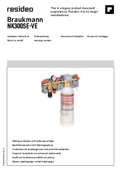
This is a legacy product document supported by Resideo. It is no longer manufactured.

Installation instructions Návod na montáz

Einbauanleitung Instrukcja montau

Instructions d'installation Istruzioni di montaggio

R32347753-001 Rev.A

Refilling combination with softening cartridge Nachfüllkombination mit Enthärtungspatrone Combinaison de remplissage avec cartouche d'adoucissement Gruppo di riempimento con cartuccia di addolcimento Doplovací kombinace se zmkcovací patrony Zespolu napelniajcego z wklad zmikczajcy

GB
1 Safety Guidelines . . . . . 3 2 Technical Data . . . . . . . . 3 3 Assembly . . . . . . . . . . . . 3 4 Start-up . . . . . . . . . . . . . 4 5 Maintenance . . . . . . . . . 4 6 Disposal. . . . . . . . . . . . . 4 7 Troubleshooting . . . . . . . 4 8 Spare Parts . . . . . . . . . . 4 9 Accessories . . . . . . . . . . 4
D
1 Sicherheitshinweise . . . . 5 2 Technische Daten . . . . . 5 3 Montage. . . . . . . . . . . . . 5 4 Inbetriebnahme . . . . . . . 6 5 Instandhaltung . . . . . . . . 6 6 Entsorgung . . . . . . . . . . 6 7 Fehlersuche. . . . . . . . . . 6 8 Ersatzteile . . . . . . . . . . . 6 9 Zubehör . . . . . . . . . . . . . 6
F
1 Règles de sécurité . . . . . 7 2 Caractéristiques
techniques . . . . . . . . . . . 7 3 Assemblage . . . . . . . . . . 7 4 Démarrage. . . . . . . . . . . 8 5 Maintenance . . . . . . . . . 8 6 Mise au rebut . . . . . . . . . 8 7 Dépannage . . . . . . . . . . 8 8 Pièces de rechange. . . . 8 9 Accessoires . . . . . . . . . . 8
I
1 Avvertenze di sicurezza . 9 2 Dati tecnici . . . . . . . . . . . 9 3 Montaggio . . . . . . . . . . . 9 4 Messa in servizio . . . . . 10 5 Manutenzione . . . . . . . 10 6 Smaltimento. . . . . . . . . 10 7 Risoluzione problemi . . 10 8 Pezzi di ricambio . . . . . 10 9 Accessori . . . . . . . . . . . 10

CZ
1 Bezpecnostní pokyny . . 11 2 Technické údaje . . . . . . 11 3 Montáz . . . . . . . . . . . . . 11 4 Spustní . . . . . . . . . . . .12 5 Údrzba . . . . . . . . . . . . .12 6 Likvidace . . . . . . . . . . .12 7 esení problém . . . . .12 8 Náhradní díly . . . . . . . .12 9 Píslusenství. . . . . . . . .12
PL
1 Wskazówki dotyczce bezpieczestwa . . . . . .13
2 Dane techniczne. . . . . .13 3 Monta . . . . . . . . . . . . .13 4 Uruchomienie . . . . . . . .14 5 Utrzymywanie w dobrym
stanie . . . . . . . . . . . . . .14 6 Utylizacja . . . . . . . . . . .14 7 Rozwizywanie
problemów . . . . . . . . . .15 8 Czci zamienne . . . . .14 9 Akcesoria . . . . . . . . . . .14

2

MU1H-1561GE23 R0240

GB

1 Safety Guidelines
1. Follow the installation instructions. 2. Use the appliance
· according to its intended use · in good condition · with due regard to safety and risk of danger. 3. Note that the appliance is exclusively for use in the applications detailed in these installation instructions (see 2 Technical Data). Any other use will not be considered to comply with requirements and would invalidate the warranty. 4. Please take note that any assembly, commissioning, servicing and adjustment work may only be carried out by authorized persons. 5. Immediately rectify any malfunctions which may influence safety.

2 Technical Data

Media

Medium:

Water

Freshwater hardness range*: 0°dH-26°dH 0°fH-46,4 °fH 0 mmol/l - 4,64 mmol/l

Connections/Sizes

Connection size discharge: HT40

Connection size:
Connection ball valve backflow preventer:

1/2" external thread G 1/4"

Pressure values

Max. inlet pressure:

10 bar

Outlet pressure:

1.5 - 4 bar

Preset outlet pressure:

1.5 bar

Operating temperatures

Max. operating temperature 30 °C medium:

Specifications

Liquid category backflow preventer BA:

4 (toxic, highly toxic, tumourigenic, radioactive materials)

Installation position:

horizontal pipework with discharge connection directed downwards

Suitable for heating systems with the following materials: aluminium, aluminium alloys, steel, copper, copper alloys and plastics.

Treated water has modified corrosive chemical parameters. Conditioning by means of inhibitors is to be provided for separately. * In order to estimate the capacity of the cartridge for fresh water hardness > 26°dH/46,4 °fH/4.64 mmol/l a manual calculation method has to be used. (see Installation Manual of the P300 cartridges incl. in the packaging of the cartridges)
3 Assembly
It is necessary during installation to follow the installation instructions, to comply with local requirements and to follow the codes of good practice.
3.1 Installation Guidelines · Installation in the inlet to the heating system, fasten
the refilling combination (VE300S) to the wall · Install in horizontal pipework with discharge
connection respectively cartridge connection directed downwards · Install at height of at least 610 mm from the ground to ensure that cartridges can be replaced · Downstream of the refilling combination (VE300S), provide settling section of at least 500 mm before integration in the heating circuit · The installation may not take place in areas or ducts where poisonous gases or vapours may be present or where flooding can occur · The installation environment should be protected against frost and ventilated well · The installation location has to be easily accessible ­ Simplified maintenance and cleaning ­ Pressure gauge at the pressure reducing valve
can be read off easily · According to EN 1717 in direction of flow, first install
the heatwater treatment unit (NK300S) and directly after it, the refill combination (VE300S) · The national installation regulations must be observed during the assembly · Requires regular maintenance in accordance with EN 806-5 · In order to avoid flooding, it is recommended to arrange a permanent, professionally dimensioned wastewater connection
3.2 Assembly instructions
To avoid stagnating water the refilling combination (NK300S must be attached as directly as possible to the service pipe! The national installation regulations apply during the assembly.

MU1H-1561GE23 R0240

3

GB

Only fasten the plastic sealing plugs by hand (without tools)
1. Thoroughly flush pipework 2. Install the refilling combination (see NK300S) 3. Install in horizontal pipework with discharge
connection directed downwards · Note flow direction (indicated by arrow) · Install in horizontal pipework with discharge
connection directed downwards · Installation height should be min. 55cm from the
floor in order to warrant safe replacement of the cartridge 4. Attach drain pipe to discharge connection (plastic pipe HT 50) 5. Install heater water treatment unit (VE300S) directly below the refilling combination (NK300S) and secure in place with the wall bracket · Install in horizontal pipeline · Note flow direction (indicated by arrow) · Install without tension or bending stresses 6. Screw the complete demineralisation cartridge (P300LES) into the heater water treatment unit (VE300) and tighten by hand.
4 Start-up
For information on start-up, see the instructions of the individual components (included in scope of delivery)
1. Adjust the back pressure (see NK300S) 2. Set to complete demineralisation (see VE300S) 3. Fill the system (see VE300S)
5 Maintenance
In order to comply with EN 806-5, water fixtures must be inspected and serviced on an annual basis. As all maintenance work must be carried out by an installation company, it is recommended that a servicing contract should be taken out.
In accordance with EN 806-5, the following measures must be taken:

5.2 Maintenance
Do not use any cleansers that contain solvents and/or alcohol for cleaning the plastic parts, because this can cause damage to the plastic components - water damage could result. Detergents must not be allowed to enter the environment or the sewerage system!
For information on maintenance, please refer to the instructions of the individual components (included in scope of delivery)
1. Valve insert and screen (see NK300S) 2. Maintenance and cleaning of cartridge insert
(see NK300S) 3. Check valve (see NK300S) 4. Replacement of the complete demineralisation
cartridge (see VE300S)
To determine the maximum capacity of the complete demineralisation cartridge, see instruction P300L
6 Disposal
For information on malfunctions / trouble shooting, please refer to the instructions of the individual components (included in scope of delivery) Observe the local requirements regarding correct waste recycling/disposal!
7 Troubleshooting
For information on malfunctions / trouble shooting, please refer to the instructions of the individual components (included in scope of delivery)
8 Spare Parts
For Spare Parts visit homecomfort.resideo.com/europe
9 Accessories
For Accessories visit homecomfort.resideo.com/europe

5.1 Inspection

For information on inspections, see the instructions of the individual components (included in scope of delivery)
1. Pressure reducing valve function control (see NK300S)
2. Drain valve function control (see NK300S)

4

MU1H-1561GE23 R0240

D

1 Sicherheitshinweise
1. Beachten Sie die Einbauanleitung. 2. Benutzen Sie das Gerät
· bestimmungsgemäß · in einwandfreiem Zustand · sicherheits- und gefahrenbewusst. 3. Beachten Sie, dass das Gerät ausschließlich für den in dieser Einbauanleitung genannten Verwendungsbereich bestimmt ist (siehe 2 Technische Daten). Eine andere oder darüber hinausgehende Benutzung gilt als nicht bestimmungsgemäß. 4. Beachten Sie, dass alle Montage-, Inbetriebnahme, Wartungs- und Justagearbeiten nur durch autorisierte Fachkräfte ausgeführt werden dürfen. 5. Lassen Sie Störungen, welche die Sicherheit beeinträchtigen können, sofort beseitigen.

2 Technische Daten

Medien

Medium:

Wasser

Frischwasserhärtebereich*: 0°dH-26°dH 0°fH-46,4 °fH 0 mmol/l - 4,64 mmol/l

Anschlüsse/Größen

Ablaufanschluss:

HT40

Anschlussgröße:

1/2" Außengewinde

Prüfanschlüsse:

G 1/4"

Druckwerte

Max. Eingangsdruck:

10 bar

Hinterdruck:

1,5 - 4 bar

Voreingestellter Ausgangsdruck:

1,5 bar

Betriebstemperaturen

Max. Betriebstemperatur des 30 °C Mediums:

Spezifikationen

Flüssigkeitskategorie Systemtrenner BA:

4 (giftige, sehr giftige, krebserzeugende, radioaktive Stoffe)

Einbaulage:

waagrecht mit Ablaufanschluss nach unten

Geeignet für Heizungsanlagen mit folgenden Materialien: Aluminium, Aluminiumlegierungen, Stahl, Kupfer, Kupferlegierungen und Kunststoffe.

MU1H-1561GE23 R0240

Aufbereitetes Wasser hat veränderte korrosionschemische Parameter. Eine Konditionierung mittels Inhibitoren ist separat vorzusehen. * Um die Kapazität der Kartusche für die Frischwasserhärte >26°dH/ 46,4°fH/4.64 mmol/la zu bestimmen, muss eine manuelle Berechnungsmethode verwendet werden (siehe Installationshandbuch der P300 Kartuschen inkl. Verpackung der Patronen)
3 Montage
Beim Einbau sind die Einbauanleitung, geltende Vorschriften sowie die allgemeinen Richtlinien zu beachten.
3.1 Einbauhinweise · Installation im Zulauf der Heizungsanlage,
Nachfülleinheit (VE300S) an der Wand befestigen · Einbau in waagrechte Rohrleitung mit
Kartuschenanschluss nach unten · Einbauhöhe min. 610 mm vom Boden aus vorsehen,
um Kartuschentausch sicher zu gewährleisten · Nach der Nachfülleinheit (VE300S) mind. 500 mm
Beruhigungsstrecke bis zur Einbindung in den Heizkreislauf vorsehen. · Der Einbau darf nicht in Räumen oder Schächten erfolgen, in denen giftige Gase oder Dämpfe auftreten und die überflutet werden können (Hochwasser) · Der Einbauort muss frostsicher und gut belüftet sein · Der Einbauort muss gut zugänglich sein ­ Vereinfacht Inspektion und Instandhaltung ­ Manometer am Druckminderer kann gut
beobachtet werden · Gemäß DIN EN 1717 in Durchflussrichtung zunächst
z.B. Nachfüllkombination (NK300S), dann unmittelbar danach Behandlungseinheit (VE300S) installieren · Instandhaltungspflichtige Armatur nach DIN EN 806-5 · Um Überflutungen zu vermeiden, empfiehlt es sich einen dauerhaften fachgerecht dimensionierten Abwasseranschluss herzustellen
3.2 Montageanleitung
Um stagnierendes Wasser zu vermeiden ist die Nachfüllkombination (NK300S) möglichst nah an die Versorgungsleitung anzuschließen! Bei der Montage gelten die nationalen Installationsvorschriften.
Kunststoff-Verschlussstopfen nur handfest anziehen (ohne Werkzeug)
Dies ist ein älteres Produktdokument, 5 das von Resideo unterstützt wird. Es
wird nicht mehr hergestellt.

D

1. Rohrleitung gut durchspülen 2. Nachfüllkombination einbauen (siehe NK300S) 3. Einbau in waagrechte Rohrleitung mit
Ablaufanschluss nach unten · Durchflussrichtung beachten (Pfeilrichtung) · Einbau in waagrechte Rohrleitung mit
Ablaufanschluss nach unten · Einbauhöhe min. 55cm von Boden aus vorsehen,
um Patronentausch sicher zu gewährleisten 4. Ablaufleitung an Ablaufanschluss anschließen
(Kunststoffrohr HT 50) 5. Heizungswasser-Behandlungseinheit (VE300)
unmittelbar nach der Nachfüllkombination (NK300) einbauen und mittels der Wandhalterung befestigen · Einbau in waagrechte Rohrleitung · Durchflussrichtung beachten (Pfeilrichtung) · Spannungs- und biegemomentfrei einbauen 6. Vollentsalzungspatrone (P300LES) in Heizungswasser-Behandlungseinheit (VE300) schrauben und handfest anziehen.
4 Inbetriebnahme
Informationen zu Inbetriebnahme siehe Anleitungen der Einzelkomponenten (im Lieferumfang enthalten)
1. Hinterdruck einstellen (siehe ) 2. Vollentsalzung einstellen (siehe VE300) 3. Anlage füllen (siehe VE300)
5 Instandhaltung
Nach DIN EN 806-5 sind Wasserarmaturen jährlich zu prüfen und instandzuhalten. Instandhaltungsarbeiten müssen durch ein Installationsunternehmen durchgeführt werden, es wird empfohlen einen Instandhaltungsvertrag mit einem Installationsunternehmen abzuschließen.
Entsprechend DIN EN 806-5 sind folgende Maßnahmen durchzuführen:

Es dürfen keine Reinigungsmittel in die Umwelt oder Kanalisation gelangen!
Informationen zur Wartung siehe Anleitungen der Einzelkomponenten (im Lieferumfang enthalten) 1. Ventileinsatz und Sieb (siehe NK300S) 2. Kartuscheneinsatz warten und reinigen (siehe NK300S) 3. Rückflussverhinderer (siehe NK300S) 4. Austausch Vollentsalzungspatrone (siehe VE300S)
Ermittlung der maximalen Kapazität der Vollentsalzungspatrone siehe EBA-P300L
6 Entsorgung
Informationen zu Störungen / Fehlersuche siehe Anleitungen der Einzelkomponenten (im Lieferumfang enthalten) Die örtlichen Vorschriften zur korrekten Abfallverwertung/entsorgung beachten!
7 Fehlersuche
Informationen zu Störungen / Fehlersuche siehe Anleitungen der Einzelkomponenten (im Lieferumfang enthalten)
8 Ersatzteile
Ersatzteile finden Sie unter homecomfort.resideo.com/ europe
9 Zubehör
Zubehör finden Sie unter homecomfort.resideo.com/europe

5.1 Inspektion

Informationen zur Inspektion siehe Anleitungen der Einzelkomponenten (im Lieferumfang enthalten)
1. Funktionskontrolle Druckminderer (siehe NK300S) 2. Funktionskontrolle Ablassventil (siehe NK300S)

5.2 Instandhaltung

Zum Reinigen der Kunststoffteile keine lösungsmittelund/oder alkoholhaltigen Reinigungsmittel benutzen, da dies zu Schädigung der Kunststoffbauteile führen kann - die Folge kann ein Wasserschaden sein!

6

MU1H-1561GE23 R0240

F

1 Règles de sécurité
1. Suivez les instructions d'installation. 2. Utilisez le dispositif
· Conformément à l'usage auquel il est destiné · Dans un bon état · En tenant dûment compte de la sécurité et des
risques. 3. Notez que le dispositif est exclusivement réservé à
une utilisation dans les applications décrites en détails dans les présentes instructions d'installation (Voir 2 Caractéristiques techniques). Toute autre utilisation sera considérée comme non conforme aux exigences et entraînera une annulation de la garantie. 4. Notez que seules les personnes autorisées sont habilitées à effectuer les travaux d'assemblage, de mise en service, de maintenance et de réglage. 5. Éliminez immédiatement tout dysfonctionnement susceptible d'entraver la sécurité.

2 Caractéristiques techniques

Fluides

Milieu:

Eau

Plage de dureté de l'eau 0°dH-26°dH

douce*:

0°fH-46,4 °fH

0 mmol/l - 4,64 mmol/l

Raccords/tailles

Taille du raccord de refoulement:

HT40

Taille du raccord:

Filetage extérieur 1/2"

Raccords de contrôle: G 1/4"

Valeurs de pression

Pression amont max.: 10 bar

Pression aval:

1,5 - 4 bar

Pression aval préréglée: 1,5 bar

Températures de fonctionnement

Température de

30 °C

fonctionnement max. du

fluide:

Spécifications

Catégorie de liquide disconnecteur BA:

4 (toxique, hautement toxique, tumorigène, matériaux radioactifs)

Position d'installation:

Tuyauterie horizontale avec raccord de refoulement dirigé vers le bas

Il s'agit d'un document produit hérité pris en charge par Resideo. Il n'est plus fabriqué.

MU1H-1561GE23 R0240

Destiné aux installations de chauffage contenant les éléments suivants : acier, cuivre, alliages cuivreux et matières plastique et aluminium, alliages d'aluminium, acier, cuivre, alliages cuivreux et matières plastique.
L'eau traitée a modifié les paramètres chimiques corrosifs. Le traitement par inhibiteurs doit avoir lieu séparément. *Il faut utiliser une méthode de calcul manuelle pour estimer la capacité de la cartouche pour la dureté de l'eau douce > 26°dH/ 46,4°fH/4,64 mmol/l. (voir le Manuel d'installation des cartouches P300 accompagnant les cartouches)

3 Assemblage
Pour le montage, respecter la notice d'installation, les consignes en vigueur et les directives générales.

3.1 · · · · ·
· ·
·
· · ·
7

Consignes d'installation Montage sur la conduite d'amenée de l'installation de chauffage, fixer l'unité de recharge (VE300S) au mur Montage dans la tuyauterie horizontale avec raccordement de la conduite d'écoulement ou de la cartouche vers le bas Prévoir une hauteur de montage minimale à 610 mm du sol afin de garantir un remplacement de la cartouche en toute sécurité Prévoir une distance de stabilisation d'au moins 500 mm en aval de la recharge (VE300S) jusqu'au raccordement au circuit de chauffage. L'installation ne doit pas être effectuée dans des lieux ou des conduits dans lesquels des gaz ou des vapeurs toxiques peuvent être présents ou en cas de risque d'inondation. L'environnement d'installation doit être protégé contre le gel et bien ventilé. Le lieu de montage doit être accessible facilement ­ Maintenance et nettoyage simplifiés ­ Pour observer facilement le manomètre situé sur
le réducteur de pression Installer d'abord la combinaison de recharge (NK300S), puis la recharge (VE300S) directement en aval dans le sens du débit conformément à la norme EN 1717 Lors du montage, les consignes d'installation nationales en vigueur doivent être respectées Nécessite un entretien régulier conformément à la norme EN 806-5 Afin d'éviter un débordement, il est recommandé d'installer un raccord d'eaux usées permanent aux dimensions professionnelles

F

3.2 Instructions d'assemblage
Pour éviter l'eau stagnante la combinaison de remplissage doit être raccordée le plus près possible sur la conduite d'alimentation! Les consignes d'installation nationales en vigueur prévalent lors du montage.

Les mesures ci-après doivent être effectuées conformément à EN 806-5 :
5.1 Inspection
Pour de plus amples informations sur les inspections à réaliser, se reporter aux instructions d'installation des différents éléments (comprises dans la livraison)

Serrer les bouchons de fermeture en plastique à la

1. Contrôler le fonctionnement du réducteur de pression

main uniquement (sans outil)

(voir NK300S)

1. Purgez entièrement la tuyauterie

2. Contrôler le fonctionnement de la vanne de purge

2. Monter la combinaison de remplissage (voir NK300S)

(voir NK300S)

3.

Montage dans une conduite horizontale avec raccord de sortie vers le bas

5.2 Maintenance

· Contrôlez la direction de l'écoulement (direction de

Pour le nettoyage des pièces en matière synthétique,

la flèche)

n'utilisez pas de produits solvants ni contenant de

· Montage dans une conduite horizontale avec

l'alcool, car cela pourrait provoquer des dégâts d'eau!

raccord de sortie vers le bas

Il est interdit de déverser les détergents dans

· Prévoir une hauteur de montage à 55cm min. du

l'environnement ou dans le réseau des égouts !

sol afin de permettre le remplacement des

cartouches

Pour de plus amples informations sur la maintenance

4. Raccorder la conduite de sortie au raccordement

à réaliser, se reporter aux instructions d'installation

(tuyau en plastique HT 50)

des différents éléments (comprises dans la livraison)

5. Monter l'appareil de traitement de l'eau de chauffage 1. Insert de soupape et tamis (voir NK300S)

(VE300) directement en aval de la combinaison de

2. Entretenir et nettoyer la cartouche (voir NK300S)

remplissage (NK300S) et l'immobiliser au moyen de la 3. Clapet anti-retour (voir NK300S)

fixation murale

4. Remplacer la cartouche d'adoucissement (voir

· Montage sur une conduite horizontale

VE300S)

· Contrôlez la direction de l'écoulement (direction de

la flèche)

Pour déterminer la capacité maximale de la cartouche

· Effectuez l'installation sans tension ni contraintes

d'adoucissement, se reporter aux instructions

de flexion

d'installation du P300L

6. Visser les cartouches de dessalement complet (P300LES) dans l'appareil de traitement de l'eau de chauffage (VE300) et les serrer à la main.

6 Mise au rebut
Pour de plus amples informations sur les défauts / la recherche de panne, se reporter aux instructions d'installation

4 Démarrage

des différents éléments (comprises dans la livraison)

Pour de plus amples informations sur la mise en service, se reporter aux instructions d'installation des différents éléments (comprises dans la livraison)

Observez les exigences locales en matière de recyclage / d'élimination conforme des déchets !
7 Dépannage

1. Régler la pression aval (voir NK300S) 2. Régler le dessalement complet (voir VE300) 3. Remplir l'installation (voir VE300)
5 Maintenance

Pour de plus amples informations sur les défauts / la recherche de panne, se reporter aux instructions d'installation des différents éléments (comprises dans la livraison)

Conformément à EN 806-5 les sraccords d'eau doivent être inspectées et entretenues une fois par an. Les travaux de maintenance doivent être réalisés par une société d'installation, nous recommandons de signer un contrat de maintenance planifiée avec une société d'installation.

8 Pièces de rechange
Pour les pièces de rechange, visitez homecomfort.resideo.com/europe
9 Accessoires
Pour les accessoires, visitez homecomfort.resideo.com/ europe

8

MU1H-1561GE23 R0240

I

1 Avvertenze di sicurezza

Adatto per impianti di

1. Rispettare le istruzioni di installazione.

riscaldamento con i seguenti

2. Utilizzare l'apparecchio

materiali: acciaio, rame,

· secondo la destinazione d'uso

leghe di rame e materiali

· solo se integro

sintetici e alluminio, leghe di

· in modo sicuro e consapevoli dei pericoli connessi.

alluminio, acciaio, rame,

3. Si prega di considerare che l'apparecchio è realizzato

leghe di rame e materiali

esclusivamente per gli impieghi riportati nelle presenti

sintetici.

istruzioni (Vedere 2 Dati tecnici). Un uso differente da

L'acqua trattata ha parametri

quello previsto è da considerarsi non conforme ai

chimici corrosivi modificati. Il

requisiti e annullerebbe la garanzia.

raffreddamento mediante

4. Osservare che tutti i lavori di montaggio, di messa in

inibitori deve essere fornito

funzione, di manutenzione e di regolazione devono

separatamente.

essere eseguiti soltanto da personale autorizzato.

* Per stimare la capacità della cartuccia per la durezza di acqua dolce

5. I guasti che potrebbero compromettere la sicurezza

> 26°dH/46,4 °fH/4,64 mmol/l è necessario utilizzare un metodo di

devono essere risolti immediatamente.

calcolo manuale. (vedere il Manuale di installazione delle cartucce P300 incluso nella confezione delle cartucce)

2 Dati tecnici

3 Montaggio

Fluidi Fluido:

Acqua

Al montaggio è necessario osservare il manuale di montaggio, le norme vigenti nonché le direttive generali.

Variazione durezza acqua dolce*:

0°dH-26°dH 0°fH-46,4 °fH 0 mmol/l - 4,64 mmol/l

Attacchi/dimensioni

Dimensione dell'attacco per HT40 scarico:

Dimensione dell'attacco: Connessione di controllo:

1 /2" filettatura esterna G 1/4"

Valori di pressione

Max. pressione a monte: 10 bar

Pressione a valle:

1,5 - 4 bar

Pressione a valle preimpostata:

1,5 bar

Temperature di esercizio

Max. temperatura di esercizio 30 °C fluido:

Specifiche

Categoria liquido disconnettore idraulico BA:

4 (materiali tossici, altamente tossici, cancerogeni, radioattivi)

Posizione di installazione:

tubatura orizzontale con connessione per lo scarico diretto verso il basso

Questo documento fa riferimento ad un dispositivo legacy non più in produzione.

3.1 Istruzioni di installazione · Installazione nella tubazione di mandata dell'impianto
di riscaldamento, fissare l'unità di trattamento dell'acqua di riscaldamento (VE300S) alla parete · Montaggio in tubazione orizzontale con attacco di scarico e/o attacco cartuccia verso il basso · Prevedere un'altezza d'installazione di min. 610 mm da terra, per garantire una sostituzione sicura della cartuccia · Dopo l'unità di riempimento (VE300S) prevedere un percorso di stabilizzazione di min. 500 mm fino all'integrazione nel circuito di riscaldamento · È vietata l'installazione in locali o pozzetti in cui si possano generare gas o vapori nocivi e soggetti a allagamento (acqua di piena) · Il luogo di installazione deve essere protetto dal gelo e deve essere ben ventilato · Il luogo di installazione deve essere di facile accesso ­ Manutenzione e pulizia semplificate ­ Il manometro del riduttore di pressione deve
essere facilmente controllabile · Secondo DIN EN 1717 installare nella direzione del
flusso prima il gruppo di riempimento (NK300S) e subito a valle l'unità di trattamento dell'acqua di riscaldamento (VE300S) · Durante il montaggio devono essere rispettate le norme di installazione nazionali. · Richiede una manutenzione regolare in conformità con la EN 806-5 · Per evitare allagamenti, si consiglia di predisporre un attacco per le acque reflue permanente e in modo professionale

MU1H-1561GE23 R0240

9

I

3.2 Istruzioni di montaggio
Per evitare acqua stagnante collegare il gruppo di riempimento (NK300S) il più vicino possibile alla tubazione di alimentazione! Durante il montaggio rispettare le norme di installazione nazionali.

In conformità alla norma EN 806-5, è necessario eseguire le seguenti operazioni:
5.1 Ispezione
Per le informazioni sui controlli, vedere le istruzioni per l'uso dei singoli componenti (comprese nel volume di fornitura)

Stringere i tappi in plastica esclusivamente a mano (senza attrezzi)

1. Controllo funzionale del riduttore di pressione (vedere NK300S)

1. Sciacquare bene la tubazione 2. Installare il gruppo di riempimento (vedere NK300S)

2. Controllo funzionale della valvola di scarico (vedere NK300S)

3.

Montaggio nelle tubazioni orizzontali con attacco dello scarico verso il basso

5.2 Manutenzione

· Osservare la direzione di flusso (direzione della freccia)
· Montaggio nelle tubazioni orizzontali con attacco dello scarico verso il basso
· Per assicurare la sostituzione della cartuccia in sicurezza, prevedere un'altezza di montaggio min. di 55 cm dal pavimento
4. Collegare il tubo di scarico all'attacco dello scarico (tubo di plastica HT 50)

Per pulire le parti in plastica non utilizzare alcun detergente contenente solvente o alcol, poiché questi potrebbero provocare danni all'acqua. Nell'ambiente o nella canalizzazione è necessario che non venga scaricato alcun detergente!
Per le informazioni sulla manutenzione, vedere le istruzioni per l'uso dei singoli componenti (comprese nel volume di fornitura)

5. Installare l'unità di trattamento dell'acqua di riscaldamento (VE300) immediatamente a valle del gruppo di riempimento (NK300S) e fissarla con il supporto a parete · Installazione su tubazione orizzontale · Osservare la direzione di flusso (direzione della freccia) · Montare senza tensione o sforzo di piegatura
6. Avvitare la cartuccia di demineralizzazione totale (P300LES) nell'unità di trattamento dell'acqua di

1. Inserto valvola e filtro (vedere NK300S) 2. Manutenzione e pulizia dell'inserto della cartuccia
(verdere NK300S) 3. Valvola di ritegno (verdere NK300S) 4. Sostituzione della cartuccia di addolcimento (vedere
VE300S)
Per la determinazione della capacità massima della cartuccia di addolcimento, vedere le istruzioni per P300L

riscaldamento (VE300) e serrarla a mano.

6 Smaltimento

4 Messa in servizio

Per le informazioni su guasti / ricerca ed eliminazione degli

Per le informazioni sulla messa in servizio, vedere le istruzioni per l'uso dei singoli componenti (comprese nel volume di fornitura)

errori, vedere le istruzioni per l'uso dei singoli componenti (comprese nel volume di fornitura) Rispettare le norme locali relative al corretto riciclaggio o smaltimento di rifiuti!

1. 2.

Regolare la pressione a valle (vedere NK300S) Regolazione della demineralizzazione totale (vedere

7

Risoluzione problemi

VE300) 3. Riempire l'impianto (vedere VE300)

Per le informazioni su guasti / ricerca ed eliminazione degli errori, vedere le istruzioni per l'uso dei singoli

5 Manutenzione

componenti (comprese nel volume di fornitura)

Stando ai requisiti posti dalle norme DIN EN 806-5 apparecchi per l'acqua vanno controllate e sottoposte a manutenzione una volta l'anno. I lavori di manutenzione devono essere eseguiti da un'azienda di installazione, consigliamo di stipulare un contratto di manutenzione con un'azienda di installazione.

8 Pezzi di ricambio
Per gli pezzi di ricambio, visita homecomfort.resideo.com/ europe
9 Accessori
Per gli accessori, visita homecomfort.resideo.com/europe

10

MU1H-1561GE23 R0240

CZ

1 Bezpecnostní pokyny
1. Respektujte návod k montázi. 2. Pouzívejte zaízení
· v souladu s urceným pouzitím · v dobrém stavu · s ohledem na bezpecnost a rizika nebezpecí. 3. Mjte na pamti, ze zaízení je urceno výhradn k pouzití v aplikacích, které jsou podrobn popsány v tomto návodu k montázi (viz 2 Technické údaje).
Jakékoliv jiné pouzití nebude povazováno za pouzití v
souladu s pozadavky a zneplatnilo by záruku. 4. Mjte prosím na pamti, ze jakákoliv montáz,
vychystávací práce, servisní práce a úpravy mohou vykonávat pouze povené osoby. 5. Okamzit opravte jakékoliv poruchy, které by mohly ovlivnit bezpecnost.

2 Technické údaje

Média

Médium:

voda

Rozsah tvrdosti vody*:

0°dH-26°dH 0°fH-46,4 °fH 0 mmol/l - 4,64 mmol/l

Pípojky/velikosti

Velikost výtlacné pípojky: HT40

Velikost pípojky: Zkusební pípojky:

1 /2" s vnjsím závitem G 1/4"

Hodnoty tlaku

Max. vstupní tlak:

10 bar

Výstupní tlak:

1,5 ­ 4 bar

Pednastavený výstupní tlak: 1,5 bar

Provozní teploty

*Aby bylo mozné odhadnout kapacitu zásobníku na cerstvou vodu o tvrdosti > 26°dH/46,4 °fH/4,64 mmol/l, je nutné pouzít rucní metodu výpoctu. (viz Návod k instalaci zásobník P300 pilozený v obalu zásobník)
3 Montáz
Pi montázi je nutné dodrzovat návod k montázi, platné pedpisy i vseobecné pokyny.
3.1 Pokyny k montázi · IInstalace v pívodu topného zaízení, upevnte
napoustcí jednotku (VE300S) na stnu · Vestavba do vodorovného potrubí s pípojkou odtoku,
pop. kartuse smující dol · Výska vestavby min. 610 mm od zem k zajistní
bezpecné výmny kartuse · Po napoustcí jednotce (VE300S) pipravit
vyrovnávací trasu dlouhou min. 500 mm az k napojení na topný okruh. · Montáz nesmí probíhat v prostorech nebo sachtách, v nichz se vyskytují plyny nebo páry, nebo které mohou být zatopeny (velká voda). · Místo montáze musí být mrazuvzdorné a dobe vtrané · Místo montáze musí být dobe pístupné ­ Zjednodusená údrzba a cistní ­ Manometr na redukcním ventilu je dobe viditelný · Podle SN EN 1717 instalujte ve smru prtoku nejprve doplovací kombinaci (NK300S), pak bezprostedn za ní napoustcí jednotku (VE300S) · U montáze je nutné dbát píslusných národních pedpis. · Vyzaduje pravidelnou údrzbu podle EN 806-5 · Aby se zamezilo vzniku zaplavení, doporucuje se zaídit permanentní, profesionáln vymené pipojení na odpad

Max. provozní teplota média: 30 °C

Specifikace

Kategorie kapalin pro potrubní oddlovac BA:

4 (toxické, vysoce toxické, karcinogenní, radioaktivní)

Montázní poloha:

vodorovné potrubí s výtlacnou pípojkou smující dol

Vhodné pro topná zaízení z tchto materiál: ocel, m, slitiny mdi a plasty; hliník, slitiny hliníku, ocel, m, slitiny mdi a plasty.

Upravená voda má zmnné korozní chemické parametry. Úpravu vlastností pomocí inhibitor je nutné zajistit zvlás.

3.2 Návod k montázi Kzabránní tvorb stagnující vody musí bt doplovací kombinace (NK300S) pipojena vco nejvtsí blízkosti napájecího potrubí! Pi montázi platí píslusné národní pedpisy. Plastovou uzavírací zátku dotahujte pouze rukou (bez náadí)
Dies ist ein älteres Produktdokument, das von Resideo unterstützt wird. Es wird nicht mehr hergestellt.

MU1H-1561GE23 R0240

11

CZ

1. Potrubí ádn vypláchnte 2. Montáz doplovací kombinace (viz NK300S) 3. Montáz do vodorovného potrubí s pípojkou odtoku
smující dol · Dejte pozor na správný smr prtoku (viz sipka) · Montáz do vodorovného potrubí s pípojkou
odtoku smující dol

Informace o údrzbáských pracích viz návody jednotlivých soucástí (jsou pilozeny k dodávce)
1. Ventilov vloka a stko (viz NK300S) 2. Údrzba a cistní kartuse (viz NK300S) 3. Zptný ventil (viz NK300S) 4. Výmna zmkovací patrony (viz VE300S)

· K zajistní moznosti výmny patron dodrzte montázní výsku min. 55 cm nad podlahou
4. Pipojte odtokové potrubí k pípojce odtoku (plastová

Urcení maximální kapacity zmkcovací patrony viz montázní návod P300L

trubka HT 50)

6 Likvidace

5. Jednotku na úpravu topné vody (VE300) instalujte

Informace o poruchách a vyhledávání závad viz návody

bezprostedn za doplovací kombinací (NK300S) a jednotlivých soucástí (jsou pilozeny k dodávce)

pipevnte ji pomocí nástnného drzáku

Respektujte místní pozadavky ohledn správné likvidace/

· Montáz do vodorovného úseku potrubí

recyklace odpad!

· Dejte pozor na správný smr prtoku (viz sipka)

· Nainstalujte bez tenze nebo naptí v ohybu

7 esení problém

6. Zasroubujte demineralizacní patronu (P300LES)

do jednotky na úpravu topné vody (VE300) a rukou ji

Informace o poruchách a vyhledávání závad viz

utáhnte.

návody jednotlivých soucástí (jsou pilozeny

k dodávce)

4 Spustní

8 Náhradní díly

Informace o uvedení do provozu viz návody

Náhradní díly viz homecomfort.resideo.com/europe

jednotlivých soucástí (jsou pilozeny k dodávce)
1. Nastavte zadní tlak (viz NK300S) 2. Nastavte úplnou demineralizaci (viz VE300)

9 Píslusenství
Píslusenství viz homecomfort.resideo.com/europe

3. Naplte zaízení (viz VE300)

5 Údrzba

Norma EN 806-5 vyzaduje kontrolní prohlídky a servis soucástí vodní soustavy jednou rocn. Jelikoz veskerou údrzbu musí provádt specializovaná instalatérská firma, doporucujeme uzavít píslusnou servisní smlouvu.
Podle normy EN 806-5 musí být provedena následující opatení:
5.1 Inspekce

Informace o kontrolních prohlídkách viz návody jednotlivých soucástí (jsou pilozeny k dodávce)
1. Kontrola funkce redukcního ventilu (viz NK300S) 2. Kontrola funkce vypoustcího ventilu (viz NK300S)
5.2 Údrzba
Soucásti z umlé hmoty necistte prostedky obsahujícími edidla ani alkohol. Mohly by je poskodit a zpsobit tak skody unikající vodou. Zádné cisticí prostedky se nesmjí dostat do kanalizace nebo okolí!

12

MU1H-1561GE23 R0240

PL

1 Wskazówki dotyczce bezpieczestwa
1. Przestrzega instrukcji montau. 2. Uywa urzdzenia
· zgodnie z jego przeznaczeniem; · w dobrym stanie; · ze wiadomoci bezpieczestwa i zagroe. 3. Naley pamita, e urzdzenie jest przeznaczone wylcznie do zastosowa okrelonych w niniejszej instrukcji montau (Patrz 2 Dane techniczne). Kade inne zastosowanie uznaje si za niezgodne z przeznaczeniem. 4. Naley równie pamita, e wszelkie prace zwizane z montaem, rozruchem, serwisowaniem i regulacj mog wykonywa wylcznie upowanieni do tego pracownicy. 5. Wszelkie usterki mogce stanowi zagroenie naley natychmiast usuwa.
2 Dane techniczne
Czynniki

Do instalacji grzewczych zawierajcych nastpujce materialy: stal, mied, stopy miedzi i tworzywa sztuczne oraz aluminium, stopy aluminium, stal, mied, stopy miedzi i tworzywa sztuczne.
Woda uzdatniona ma zmodyfikowane korozyjne parametry chemiczne. Kondycjonowanie przy uyciu czynników hamujcych ma by zapewnione oddzielnie. *Do oceny wydajnoci wkladu filtrujcego w przypadku wody slodkiej o twardoci > 26°dH/46,4 °fH/4,64 mmol/l naley zastosowa rczn metod obliczeniow. (patrz Instrukcja montau wkladów filtrujcych P300 umieszczona w opakowaniu wkladu filtrujcego)
3 Monta
Podczas montau przestrzega instrukcji montau, obowizujacych przepisów oraz ogólnych zasad

Czynnik:

Woda

Skala twardoci wody slodkiej*:

0°dH-26°dH 0°fH-46,4 °fH 0 mmol/l - 4,64 mmol/l

Przylcza/rozmiary

Rozmiar przylczy po stronie HT40

wyplywu:

Rozmiar przylczy:

1 /2", gwint zewntrzny

Polczenie testowe:

G 1/4"

Wartoci cinienia

Maks. cinienie wlotowe: 10 bar

Cinienie wylotowe:

1,5 - 4 bar

Wstpnie ustawione cinienie wylotowe:

1,5 bara

Temperatury robocze

Maks. temperatura robocza 30 °C czynnika:

Specyfikacja

Urzdzenie zapobiegajce przeplywowi wstecznemu BA, do pracy z cieczami:

4 (toksyczny, bardzo toksyczny, karcynogenny, materialy radioaktywne)

Pozycja montaowa:

System rur poziomych z przylczem wylotowym skierowanym w dól

To jest archiwalna dokumentacja produktu z portfolio Resideo. Produkt nie jest ju produkowany.

3.1 Wskazówki dotyczce montau · Monta w doplywie instalacji grzewczej, jednostka
napelniajca (VE300S) montowana na cianie · Monta w poziomym przewodzie rurowym z
przylczem odplywu lub przylczem wkladu demineralizacyjnego do dolu · W celu zapewnienia latwej wymiany wkladów demineralizacyjnych zaplanowa wysoko montau min. 610 mm od podlogi. · Za jednostk dopelniajc (VE300S) zaplanowa przed wlczeniem w obieg grzewczy odcinek uspokajajcy o dlugoci min. 500 mm. · Nie wolno montowa w pomieszczeniach lub szybach, w których wystpuj trujce gazy lub pary i które moglyby ulec zalaniu (powód) · Miejsce montau musi by wolne od mrozu i dobrze przewietrzane
· Miejsce montau musi by latwo dostpne ­ Uproszczona konserwacja i czyszczenie
­ Manometr przy reduktorze cinienia musi by dobrze widoczny
· Zgodnie z norm DIN EN 1717 w kierunku przeplywu naley najpierw zamontowa kombinacj napelniajc (NK300S), a bezporednio potem jednostk napelniajc (VE300S)
· Przy montau naley przestrzega lokalnych krajowych przepisów montaowych
· Wymaga regularnej konserwacji zgodnie z EN 806-5
· Aby zapobiec zalaniu, zaleca si przygotowanie stalego, fachowo zwymiarowanego zlcza odplywu kanalizacyjnego.

MU1H-1561GE23 R0240

13

PL

3.2 Instrukcja montau

5.1 Kontrola

Aby unikn stagnacji wody, zespól napelniajcy (NK300S) naley podlczy moliwie blisko instalacji zasilajcej! Przy montau naley przestrzega lokalnych krajowych przepisów montaowych.
Dokrci mocno zalepki, tylko rcznie (bez uycia narzdzi)
1. Dokladnie przepluka przewód przylczeniowy. 2. Wmontowa zespól napelniajcy (patrz NK300S) 3. Monta wpoziomym przewodzie rurowym
zprzylczem spustowym skierowanym wdól · Przeplyw w kierunku wskazanym przez strzalk · Monta wpoziomym przewodzie rurowym
zprzylczem spustowym skierowanym wdól · Wysoko montau od podloa powinna wynosi
min. 55 cm, zapewnia to latw wymian wkladu 4. Przylczy przewód odprowadzajcy do przylcza
wylotowego (rura z tworzywa sztucznego HT 50) 5. Jednostk przygotowania wody grzewczej (VE300)
wbudowa bezporednio po zespole napelniajcym (NK300S) i umocowa uchwytem ciennym · Montowa rurocig w poziomie · Przeplyw w kierunku wskazanym przez strzalk · Zamontowa w stanie wolnym od napre i
momentów zginajcych. 6. Wkrci wklad pelnego odsalania (P300LES) do
jednostki przygotowania wody grzewczej (VE300) i mocno dokrci rk.
4 Uruchomienie
Informacje dotyczce rozruchu znale mona w instrukcjach poszczególnych komponentów (nale do zakresu dostawy)
1. Ustawi cinienie wsteczne (patrz NK300S) 2. Ustawi pelne odsalanie (patrz VE300) 3. Napelni urzdzenie (patrz VE300)
5 Utrzymywanie w dobrym stanie
Aby zachowa zgodno z EN 806-5, armatura wodna musi by sprawdzana i serwisowana co roku. Prace konserwacyjne musz by wykonywane przez firm montaow, zalecamy zawarcie umowy serwisowej z firm instalacyjn.
Zgodnie z norm EN 806-5, naley wykona nastpujce czynnoci:

Informacje dotyczce inspekcji znale mona w instrukcjach poszczególnych komponentów (nale do zakresu dostawy)
1. Skontrolowa funkcjonowanie reduktora cinienia (patrz NK300S)
2. Skontrolowa funkcjonowanie zaworu spustowego (patrz NK300S)
5.2 Utrzymywanie w dobrym stanie
Do czyszczenia czci z tworzyw sztucznych nie naley uywa rozpuszczalników i/lub rodków zawi erajcych alkohol. Prowadzi to moe do uszkod zenia tych czci, a konsekwencj tego mog by szkody wodne! Nie wolno uwalnia detergentów do rodowiska ani do kanalizacji ciekowej!
Informacje dotyczce prac konserwacyjnych znale mona w instrukcjach poszczególnych komponentów (nale do zakresu dostawy)
1. Wkladka zaworu i sito (patrz NK300S) 2. Konserwacja i czyszczenia zespolu wkladki zaworu
(patrz NK300S) 3. Zawór kontrolny (patrz NK300S) 4. Wymiana wkladu zmikczajcego (patrz VE300S)
Ustalenie maksymalnej pojemnoci wkladu zmik czajcego, patrz instrukcja P300L
6 Utylizacja
Informacje dotyczce zaklóce / szukania bldów znale mona w instrukcjach poszczególnych komponentów (nale do zakresu dostawy) Naley stosowa si do miejscowych przepisów dotyczcych prawidlowego wykorzystania odpadów, wzgldnie ich utylizacji.
7 Rozwizywanie problemów
Informacje dotyczce zaklóce / szukania bldów znale mona w instrukcjach poszczególnych komponentów (nale do zakresu dostawy)
8 Czci zamienne
Czci zamienne zobacz stron homecomfort.resideo.com/ europe
9 Akcesoria
Akcesoria zobacz stron homecomfort.resideo.com/europe

14

MU1H-1561GE23 R0240

MU1H-1561GE23 R0240

15

Manufactured for and on behalf of
Pittway Sàrl, Z.A., La Pièce 4, 1180 Rolle, Switzerland
by its authorised representative Ademco 1 GmbH

For more information homecomfort.resideo.com/europe
Ademco 1 GmbH, Hardhofweg 40, 74821 MOSBACH, GERMANY
Phone: +49 6261 810 Fax: +49 6261 81309

© 2020 Resideo Technologies, Inc. All rights reserved.

Subject to change. MU1H-1561GE23 R0240


References

Acrobat Distiller 17.0 (Windows) FrameMaker 12.0