RELIABILT Electronic Deadbolt with Keypad
Model Numbers: 92640-025/92640-026/92640-027
Item Numbers: 5059215/5059216/5059217
Customer Service: 866-386-7941, 8:00 a.m. - 7:00 p.m. (Mon-Fri), 9:00 a.m. - 6:00 p.m. (Sat), 1:00 p.m. - 5:00 p.m. (Sun)
Email: ascs@lowes.com
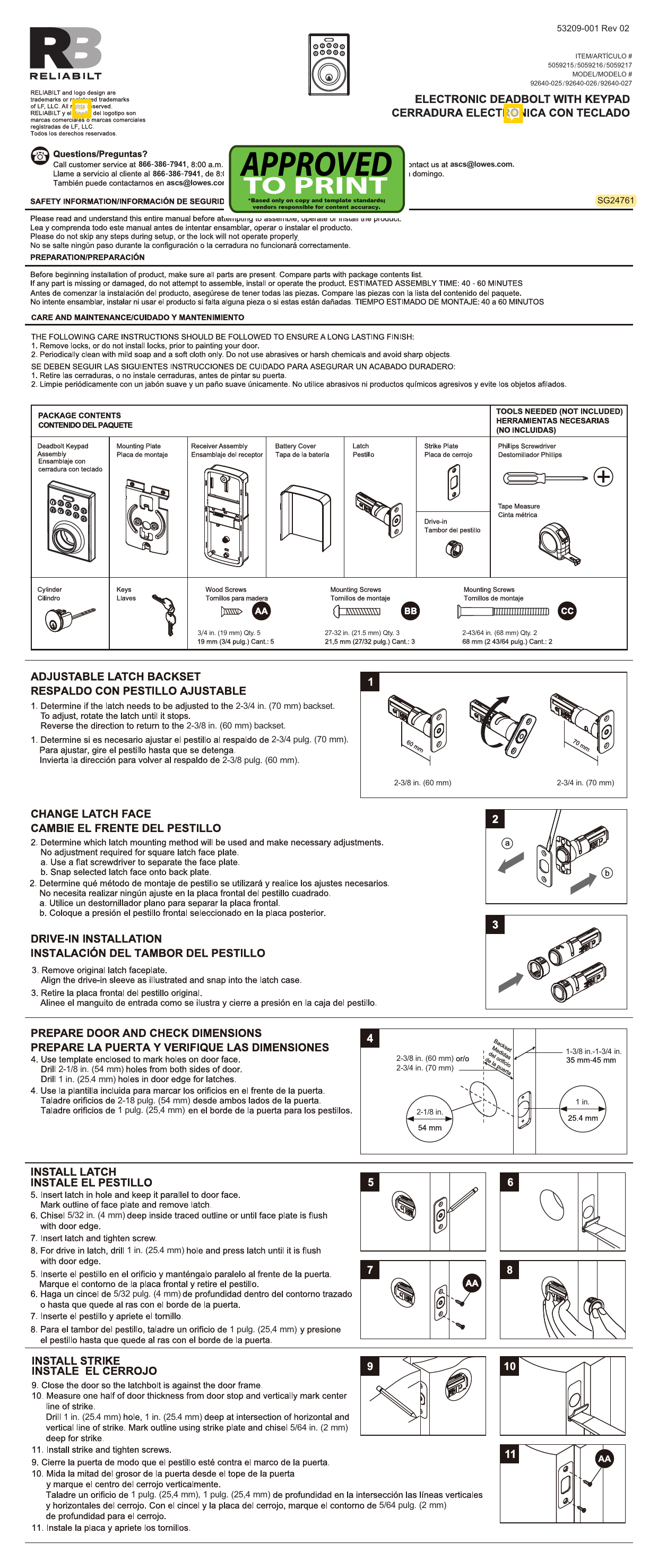
Safety Information: ⚠️ Please read and understand this entire manual before attempting to assemble, operate, or install the product. Do not skip any steps during setup, or the lock will not operate properly.
Preparation and Maintenance
Preparation
Before beginning installation, ensure all parts are present by comparing them with the package contents list. If any part is missing or damaged, do not attempt to assemble, install, or operate the product. Estimated assembly time: 40-60 minutes.
Care and Maintenance
To ensure a long-lasting finish:
- Remove locks or do not install locks prior to painting your door.
- Periodically clean with mild soap and a soft cloth only. Avoid abrasives, harsh chemicals, and sharp objects.
Package Contents
| Item | Description |
|---|---|
| 1 | Deadbolt Keypad Assembly |
| 2 | Mounting Plate |
| 3 | Receiver Assembly |
| 4 | Battery Cover |
| 5 | Latch |
| 6 | Strike Plate |
| 7 | Cylinder |
| 8 | Keys |
| 9 | Wood Screws |
| 10 | Mounting Screws (AA) - 3/4 in. (19 mm) Qty. 5 |
| 11 | Mounting Screws (BB) - 27-32 in. (21.5 mm) Qty. 3 |
| 12 | Mounting Screws (CC) - 2-43/64 in. (68 mm) Qty. 2 |
Tools Needed (Not Included)
- Phillips Screwdriver
- Tape Measure
Installation Steps
Step 1: Adjustable Latch Backset
Determine if the latch needs to be adjusted to the 2-3/4 in. (70 mm) backset. To adjust, rotate the latch until it stops. Reverse the direction to return to the 2-3/8 in. (60 mm) backset.
Diagram shows rotating the latch mechanism.
Step 2: Change Latch Face
Determine which latch mounting method will be used and make necessary adjustments. No adjustment is required for a square latch face plate. Use a flat screwdriver to separate the face plate from the back plate, then snap the selected latch face onto the back plate.
Diagram shows separating a latch faceplate and attaching it to the backplate.
Step 3: Drive-in Installation
Remove the original latch faceplate. Align the drive-in sleeve as illustrated and snap it into the latch case.
Diagram shows removing the original faceplate and fitting the drive-in sleeve.
Step 4: Prepare Door and Check Dimensions
Use the enclosed template to mark holes on the door face. Drill 2-1/8 in. (54 mm) holes from both sides of the door. Drill 1 in. (25.4 mm) holes in the door edge for the latch. Ensure door thickness is between 1-3/8 in. and 1-3/4 in. (35 mm - 45 mm).
Diagrams show template placement, drilling hole sizes (2-1/8 in. for face, 1 in. for edge), and door thickness.
Step 5: Install Latch
Insert the latch into the hole, keeping it parallel to the door face. Mark the outline of the faceplate and remove the latch. Chisel 5/32 in. (4 mm) deep inside the traced outline or until the faceplate is flush with the door edge. Insert the latch and tighten the screw. For drive-in latches, drill a 1 in. (25.4 mm) hole and press the latch until it is flush with the door edge.
Diagrams show inserting the latch, marking, chiseling, tightening screws, and drive-in installation.
Step 6: Install Strike
Close the door so the latchbolt is against the door frame. Measure half the door thickness from the door stop and mark the vertical center line of the strike. Drill a 1 in. (25.4 mm) hole, 1 in. (25.4 mm) deep at the intersection of the horizontal and vertical lines for the strike. Mark the outline using the strike plate and chisel 5/64 in. (2 mm) deep for the strike. Install the strike and tighten the screws.
Diagrams show positioning the strike, measuring, drilling, chiseling, and installing.
Step 7: Install Keypad Assembly
Pass the IC wire under the latch to the interior side of the door, and insert the tailpiece through the crank of the latch.
Diagram shows routing the wire and inserting the tailpiece.
Step 8: Install Inside Mounting Plate
Pass the IC wire through the wire hole of the mounting plate. Fix the mounting plate with screws (AA). If the outside lock assembly is lopsided, loosen the screws to adjust its position and tighten them again.
Diagram shows passing the wire and securing the mounting plate.
Step 9: Identify Door Handing
Face the door from the outside. The door is left-handed if the hinges are on the left side of the door. The door is right-handed if the hinges are on the right side of the door.
Diagrams illustrate left-handed and right-handed doors based on hinge location.
Step 10: Adjust Thumb Turn Piece
Rotate the thumb turn piece to the LEFT 45° for right-handed doors. Rotate the thumb turn piece to the RIGHT 45° for left-handed doors.
Diagrams show the 45° rotation for left and right-handed doors.
Step 11: Install Interior Assembly
To remove the battery cover, push up on the cover. Align the colored edges of the connectors and ensure a tight cable connection. Make sure the torque blade is still in the horizontal position and install the interior assembly. Test the turnpiece for smooth rotation. Secure the interior assembly with the supplied screws (CC).
Diagrams show battery cover removal, IC wire connection, interior assembly installation, and securing with screws.
Step 12: Insert Batteries
Insert 4 (AA) 1.5 V alkaline batteries. Place the battery cover and ensure the latch is still in the unlocked position.
Diagrams show battery insertion and cover placement.
Template
Use the provided template to mark holes on the door edge. Fold on the dotted lines and fit on the door edge. Mark the 1 in. (25.4 mm) hole at the center of the door edge for both 2-3/8 in. (60 mm) and 2-3/4 in. (70 mm) backsets. The template also indicates hole sizes for different door thicknesses (1-3/8 in. to 1-3/4 in.).
Diagram shows a circular template with markings for different backsets and door thicknesses.
Limited Lifetime Warranty
The Manufacturer extends a Limited Lifetime Mechanical and Finish Warranty to the original "User" of this product against defects in materials and workmanship as long as the User occupies the residential premises upon which the product was originally installed. Upon return of a defective product to the Manufacturer, the Manufacturer shall either replace, repair, or refund the purchase price in exchange for the product. This warranty does not cover abused or misused products or those products used in commercial applications. No other warranties, express or implied, are made with respect to the product, including but not limited to any implied warranty of merchantability or fitness for a particular purpose. The Manufacturer DOES NOT authorize any person to create for it any obligation or liability in connection with the product. The Manufacturer's maximum liability here under is limited to the purchase price of the product, and in no event shall the company be liable for any consequential, indirect, incidental, or special damages of any nature arising from the sale or use of this product, whether in contract, tort, strict liability, or otherwise.
This warranty is also provided in Spanish in the original document.
Printed in Taiwan.
