File info: application/pdf · 4 pages · 768.84KB
ESSENCE ELECTRICAL SPECS & DIAGRAMS
ESSENCE ELECTRICAL SPECS & DIAGRAMS - Big Ass Fans
© 2018 DELTA T LLC ALL RIGHTS RESERVED. ESS-INST-240-ENG-01 REV. B 02/07/2020 Terminal Description 1 0–10 VDC Speed Ref. 3 Status LED ( )
Full PDF Document

If the inline viewer fails, it will open the original document in compatibility mode automatically. You can also open the file directly.
Extracted Text
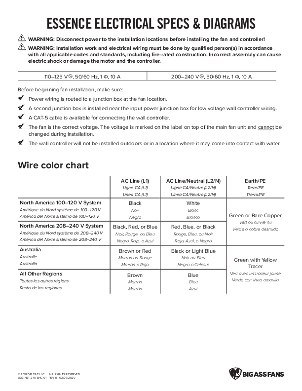
ESSENCE ELECTRICAL SPECS & DIAGRAMS
WARNING: Disconnect power to the installation locations before installing the fan and controller!
WARNING: Installation work and electrical wiring must be done by qualified person(s) in accordance with all applicable codes and standards, including fire-rated construction. Incorrect assembly can cause electric shock or damage the motor and the controller.

110�125 V , 50/60 Hz, 1 , 10 A

200�240 V , 50/60 Hz, 1 , 10 A

Before beginning fan installation, make sure: Power wiring is routed to a junction box at the fan location. A second junction box is installed near the input power junction box for low voltage wall controller wiring. A CAT-5 cable is available for connecting the wall controller. The fan is the correct voltage. The voltage is marked on the label on top of the main fan unit and cannot be changed during installation. The wall controller will not be installed outdoors or in a location where it may come into contact with water.

Wire color chart

North America 100�120 V System
Am�rique du Nord syst�me de 100�120 V Am�rica del Norte sistema de 100�120 V
North America 208�240 V System
Am�rique du Nord syst�me de 208�240 V Am�rica del Norte sistema de 208�240 V
Australia
Australie Australia
All Other Regions
Toutes les autres r�gions Resto de las regiones

AC Line (L1)
Ligne CA (L1) L�nea CA (L1)
Black
Noir Negro
Black, Red, or Blue
Noir, Rouge, ou Bleu Negro, Rojo, o Azul
Brown or Red
Marron ou Rouge Marr�n o Rojo
Brown
Marron Marr�n

AC Line/Neutral (L2/N)
Ligne CA/Neutre (L2/N) L�nea CA/Neutro (L2/N)
White
Blanc Blanco
Red, Blue, or Black
Rouge, Bleu, ou Noir Rojo, Azul, o Negro
Black or Light Blue
Noir ou Bleu Negro o Celeste
Blue
Bleu Azul

Earth/PE
Terre/PE Tierra/PE
Green or Bare Copper
Vert ou cuivre nu Verde o cobre desnudo
Green with Yellow Tracer
Vert avec un traceur jaune Verde con l�nea amarilla

� 2018 DELTA T LLC ALL RIGHTS RESERVED. ESS-INST-240-ENG-01 REV. B 02/07/2020

Fan and wall controller wiring

L1/AC LINE EARTH/PE L2/AC NEUTRAL

Power Supply
Power Cable
BLACK OR BROWN
GREEN OR GREEN/YELLOW
WHITE OR BLUE

WHITE

ORANGE
BROWN (Not Used)
Controller Input Cable

GREEN

RED

RJ45 Adapter Cable
Terminal Description 1 +0�10 VDC Speed Ref. 3 Status LED (+) 6 Status LED (-) 7 +10 VDC Supply 8 DC Common

BLACK

BLUE & YELLOW Fire Alarm Shutdown Closed: Fan Enabled Open: Fan Disabled To restart the fan, close the circuit and turn off power to the fan for 60 seconds.

To Wall Controller

CAT-5 Cable to Wall Controller

� 2018 DELTA T LLC ALL RIGHTS RESERVED. ESS-INST-240-ENG-01 REV. B 02/07/2020

Fire relay wiring (optional)
In the configuration shown, fan operation is disabled when power is applied to the fire relay. To restart the fan and clear the fire fault, close the circuit and turn off power to the fan for 60 seconds.

RED WHITE

From Main FACP or NAC Box (if applicable)

ORANGE (NO)

YELLOW (NC) BLUE (C)

RED (+) WHITE (-)

Controller Input Cable

YELLOW

Coil: 20�32 VDC @ 20 mA BLUE

See previous page for wall controller wiring

To Wall Controller

� 2018 DELTA T LLC ALL RIGHTS RESERVED. ESS-INST-240-ENG-01 REV. B 02/07/2020

0�10 VDC automation wiring (optional)

0�1 VDC = Fan off 1�10 VDC = Fan run and speed reference

Fan speed % per VDC applied

VDC In 0�1 1�10

% Speed Fan off 15�100%

100 90 80 70 60 50 40 30 20 10 0 0 1 2 3 4 5 6 7 8 9 10
VDC In

Controller input cable

1 White +0�10 VDC Speed Ref.

2 Brown Not Used

3 Orange Status LED (+)

4 Yellow Fire Alarm Shutdown

Closed: Fan Enabled

5 Blue

Open: Fan Disabled To restart the fan, close the circuit and

turn off power to the fan for 60 seconds.

6 Green Status LED (-)

7 Red

+10 VDC Supply

8 Black DC Common

1�10 V Analog Speed Reference

Speed %
WHITE

Controller Input Cable

BLUE & YELLOW Fire Alarm Shutdown Closed: Fan Enabled Open: Fan Disabled To restart the fan, close the circuit and turn off power to the fan for 60 seconds.

RED BLACK BLACK

BROWN, ORANGE, GREEN, RED (NOT USED)

� 2018 DELTA T LLC ALL RIGHTS RESERVED. ESS-INST-240-ENG-01 REV. B 02/07/2020