File info: application/pdf · 244 pages · 131.37MB
Document preview and download links are below.
Extracted Text
FOR ENG IN EER S AND EN GI NEER ING MANAGERS
JUNE 7, 1974
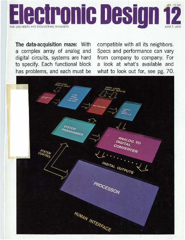
The data-acquisition maze: With a complex array of analog and digital circuits, systems are hard to specify. Each functional block
has problems, and each must be
compatible with all its neighbors. Specs and performance can vary from company to company. For a look at what's available and
what to .look out for, see pg. 70.
YOU HUM THC TUllC, CXAR PLL WILL SlllQ IT
XR-2567
XR-210
~ �XR-215
XR -567
Exar PLL
We have the broadest chorus line of Phase Lock Loop circuits available today. Take a brief look at our everexpanding PLL line:
The XR-210 is designed fo r FSK Modulation and Demodulation and feat ures a self-contained output logic driver, compatible with RS-232C requirements.
Use the XR-215 fo r FM or FSK demodulation , frequency synthesis and filter tracking . It has a 5V to 26V supply range and 0.5 Hz to 35 MHz frequency bandwidth. Whatsmore, it's bipolar logic compatible.
The XR-8200 is a do-it-yourself build ing block. With this you design you r own PLL c ircuits by selecting external connecti ons and components. You get instant pro-
totypes with minimum fuss and costs. Moving right along . .. the XR -567 PLL is designed for
tone and frequency decoding . It has a bandwidth adjustable from O to 14%, sinks up to 100 mA of load current and has a logic compatible output. Our dual version , the XR-2567, is a real hummer with even better temperature t rack ing and matching cl:laracteristics. Power supply rejection is improved by an order of magnitude over the single version. The dual outputs can switch up to 100 mA at 26 volts.
All together now. We would like to send you the complete musical score on our PLL products. Our data sheets are good and they 're filled with applications data. Write now, write.
r EXAR SPEAKS YOUR LANGUAGE
EXAR INTEGRATED SYSTEMS
A Su bsidiary of R-ohm Co rporation 16931 Mllllken Ave ., Irvine, CA. 92705 (714) 546-8780 TWX 910-595-1721
EXAR SALES REPRESENTATIVES Alabama , Georgia, Mississippi, North Carolina , South Carolina and Tenneasee: K & E Associates, Kennesaw, Georgia (404) 974-4264 Arkansas, Louisiana , Oklahoma and Texa1: Evans-M cDowell , Dallas, Texas (214) 238-7157 California: De Angelo, Rothman and Co .. Culver City (2 13) 398-6239 , Logan Sa les Co., Redwood City (415) 369-6726 Connecticut, Maine, Massachu setts, New Hampshire, Rhode Island and Vermont: Com-Sale, Waltham , Massachusetts (617) 890-0011 , Meriden, Conn. (203) 634-0179 Indiana, Kentucky and Ohio: McFadden Sales, Columbus, Ohio (614) 221 -3363 Idaho, Oregon and WHhington: SD � A'
:;~:~1~~to~, 5~~~� ~e8~~:'aun~' 1~~.s~n;!~"s~~Pn~, ~~~~~~ (~g~)1~9;-~~4~11~~':1~~,~~'-fs0o"u1~)5~~~aW!nn1~~1Va~1~~k~8r~li~o~:h (i~~oc~~~~~~~illo~8'l~~~:: ~~~~~~~v:~~
(215) 657-2213 New Jersey (North) and New York : MOS Associates, Floral Pa rk, New Yo rk (516) 694-5923 Canada: Harva rd Electronic Sales, Laval, Quebec (514) 681-1400 EXAR DISTRIBUTORS Californ ia : EEP Corporation, Culver City (213) 838-1912, lntermark Elect ronics, San Carlos (415) 592-1641 , San Diego (714) 279-5200, Sa nta Ana (714) 540-1322 Colorado: lntermark Electron ics, Denver (303) 936-8284 Indiana: Graham Electronics , Indianapolis {317) 634-8202 Massachuaelts: Gerber Electronics, Ded h~m (617) 329-2400 Washington : lntermark Electronics, Seattle (206) 767-3160
EL ECTRON IC D ESIGN 12, June 7, 1974
INFORMATION RETRIEVAL NUMBER '2
��� but we're pussycats to do business with
Our products are tough, but our people aren't. ..
who are really concerned about your problem ...
and that's the beauty of dealing with Cherry.
to production scheduling and customer service men
You see. we can control the quality of our switches who follow-up and expedite to make sure we keep
because we fabricate most of our own parts
our delivery promise to you .
(moldings, stampings, springs, printed circuits, etc.)
Of course we're proud of our modern facilities
And we can keep the price down because we 're
and equipment ... but what we 're proudest of is our
loaded with automatic equipment to handle
reputation for customer service. Try some.
high volume.
_.4 ��Test a free sample "tiger" from the pussycats at Cherry.
But the real difference is in the people you work
I Ask for our latest catalog which contains complete
with at Cherry ... from your first contact with a
... information on all our switches and keyboards,
, . . _ and we'll include a free sample switch . Just TWX
technically trained sales representative .. .through
910-235-1572 ... or PHONE 312-689-7700 ...
careful analysis and recommen~i�E~�;m1e the ceade< .eN;ce oumbe< below.
CHERRY ELECTRICAL PRODUCTS CORP. � 3609 Sunset Avenue , Waukegan , Illinois 60085
ELECTRONIC DATA ENTRY KEYBOARDS � ELECTRONIC DESK TOP CALCULATORS
INFORMATION RETRIEVAL NUMBER 3
~l~ctronic Design 12
NEWS
29 News Scope 34 Better and cheaper integrated circuits are on the way
with two advances in processing. 36 Electron-beam projection system gives 3-way improvement in ICs. 38 Domestic satellites promise to revolutionize communications. 44 Electrochromic display offers challenge to liquid crystals. 48 Low-cost, standard MIC packages are within the designer's reach. 55 Washington Report
TECHNOLOGY
70 FOCUS on data-acquisition equipment: This special report examines the maze of
.error sources that can plague data-acquisition equipment. Many subtleties and
tradeoffs in sub-system design and selection are also discussed.
92 Opto-isolator logic units add flexibility to digital design . They provide inputto-output isolation , low noise feedthrough and response to de and fast pulses.
100 MOS/LSI microprocessor selection: Here� are basic hardware, software and design points to consider before you start a microcomputer design.
116 Get standby LSI memory power, and you have a nonvolatile setup that competes with core. Pulsed refreshed cycles allow a small battery to preserve data.
124 Curb analog data errors with PCM recording techniques. They offer higher S/N ratios and accuracies than either AM or FM methods.
130 Calculate with a v/f converter. Only a few simple modifications are needed to allow accurate multiplication, division and square-root extraction :
136 Match impedances with tapered lines when you test microwave transistors,
and you 'll avoid the destruction of expens.ive devices.
142 Start your own electronics business-but look before you leap.
I
150 Ideas for Design: Current clamp blocks destructive discharges of large filter
capacitors ... A/d converter remembers signal peaks whose duration is less
t
than 50 ns ... Simplified biofeedback circuit detects alpha-wave activity. 156 International Technology
PRODUCTS
168 Modules & Subassemblies: High-speed s/h circuit gives gain up to 1000.
158 Data Processing
194 Microwaves & Lasers
179 Integrated Circuits
204 Instrumentation
184 Packaging & Materials
212 Discrete Semiconductors
190 Components
217 Power Sources
Departments
69 Editorial: The job that couldn 't be done
7 Across the Desk
236 Advertisers ' Index
224 Application Notes
238 Product Index
225 Design Aids
240 Information Retrieval Card
226 New Literature
Cover: Photo by Chadman Studios , Boston , courtesy of Datel Systems Inc.
ELECTRONIC DESIGN is published b iweekly by Hayden Publishing Company, Inc., 50 Essex St. , Rochelle Park,
N. J . 0 76 62. Jam es S. Mulholland Jr. , Presid ent. Printed at Brown Printing Co., Inc., Waseca, Minn . Controlled circulation postage pa id at Waseca, Minn ., and New York. N . Y., postage pending Rochelle Park. N . J . Copy.
right � 1974. Hayden Publishing Company, Inc. 84.392 copies this issue.
ELECTRO IC D ESIGN 12. June 7, 197 4
3
1� crocom
Intel's new 8080 n-channel microcomputer is hereincredibly easy to interface, simple to program and with up
to 100 times the performance of p-channel MOS microcomputers. Best of all, the 8080 is real - in production at Intel and available in volume quantities, today It's also available through distributors along with a growing line of peripheral circuits and a new version of the Intellec 8, a program and hardware development system for the 8080,
all supported with software packages, design documentation and manuals, and backed by more than 100 man years of microcomputer expertise.
The 8080 is the inevitable successor to complex custom MOS and many large discrete logic subsystems. It is the industry's first general purpose n-channel microcomputer and the first high performance -single-chip CPU, with extremely simple interface requirements and straightforward programming. It runs a full instruction cycle in 2 microseconds.
. As such, the 8080 extends the economic
benefits of Intel's p-channel microcomputers to a new universe of systems that need fast, multi-port controllers and processors.These systems include intelligent terminals, point of sale systems, process and numeric controllers, advanced
4
ELECTRON IC D ESIGN 12. June 7, 1974
to so tware,t
puter
� IS
ere.
calculators, word processors, self-calibrating instruments, d ata loggers, communica-
tions controllers, and many more.
You can use 256 input and 256
output channels, handle almost
unlimited interrupt levels, directly
access 64 kilobytes of memory;
and put many satellite 8080 proc-
essors around a single memory
Interfacing is minimal and
design is easy with the 8080
because all controls are fully
decoded on the CPU chip itself and inputs and outputs are TIL compatible.There are separate data, address and control buses.
The 8080 microcomputer has 78 basic instructions, including the
.
8205 8210 8212 8216 8201
'
. .. . . ~-'
'
'
. , "
. ";
'
AVL: AVL:
l..,.'
.
AVL: AVL:
AVL:
I
' � _,
NOW
NOW NOW 3RD Q
4TH Q
INTEL 8080 PRODUCT FAMILY
8008 set plus new ones that make possible such features as vectored multi-level
interrupt, unlimited subroutine nesting and very fast decimal and binary
arithmetic.
Program development for the 8080 can be done either on a large
computer using the Intel software cross products (PL/M systems language
compiler, macro-assembler and simulator), or on an Intellec 8 development
system with a resident monitor, text editor and macro- assembler
The new 8080 product family includes performance matched peripheral and
memory circuits configured to minimize design effort and maximize systerri
performance. Large, low cost RAMs, ROMs, PROMs and I/O devices are available
now and we will soon announce other 8080 LSI support circuits.
The 8080 is easier to use and more economical than any high performance
microcomputer in sight. It's here now, in volume, from the inventors.of the micro-
computer and the people who lead the industry in production and design support.
Intel Corporation, 3065 Bowers Avenue, Santa Clara, California 95051 .
(408) 246-7501 .
inter Microcompuiers. First from the beginning.
INFO RM A TION RETRI EVA L NUMBER 4
ELECTRON IC D ES IGN 12. Jun e 7, 1974
5
FLAT INTERCONNECTS YOUR COMPLETE SOURCE
Ribbon Cable I IC Interconnects I Custom Harnesses You're sold on flat cable. now buy it at its best.
Precise. compact cable packages to fit your specifications perfectly, computer-loomed for unmatched versatility by Woven Electronics.
Handling ease of independent non-bonded leads speeds production. cuts cost, while tecHnical characteristics outrank other flat cable forms.
Make Woven your source for jumpers, continuous rolls, special harnesses. all your interconnect needs.
WOUED ELEETRODIES
P.O. Box 189 Mauldin, South Carolina 29622 803/963-5131
INFORMATION RETRIEVAL NUMBER 5 6
Vice President, Publisher
Peter Coley
Editors
Editorial Offices 50 Essex St. Rochelle Park, N.J. 07662 (201) 843-0550 TWX: 710-990 5071 Cable: Haydenpubs Rochellepark Editor-in-Chief George Rostky Managing Editors: Ralph Dobriner Michael Elphick Associate Editors: Dave Bursky Jules H. Gilder Morris Grossman Seymour T. Levine John F. Mason Stanley Runyon Edward A. Terrero Richard L. Turmail
Contributing Editors: Peter N. Budzilovich Robert Wallins
Editorial Field Offices
East Jim McDermott, Eastern Editor P.O. Box 272 Easthampton, Mass. 01027 (413) 527-3632
West David N. Kaye, Senior Western Editor 2930 West Imperial Highway Inglewood, Calif. 90303 (213) 757-0183 Northe K. Osbrink, Western Editor 112 Coloma St. Santa Cruz, Calif. 95060 (408) 426-3211 Washington Heather M. David, Bureau Chief 2506 Eye St., N.W. Washington, D.C. 20037
Editorial Production
Marjorie A. Duffy
Art
Art Director, William Kelly Richard Luce Anthony J. Fischetto
Production
Manager, Dollie S. Vieblg Helen De Polo Anne Molfetas Christopher G. Hill
Circulation
Manager, Evan Phoutrides
Information Retrieval
Peggy Long
Promotion
Manager, Jeffrey A. Weiner Karen Kerrigan (Reprints)
ELECTRONIC DESIGN 12, June 7, 1974
(across the desk]
Nuclear transients can be complicated
on who supplies the data, this can result in a �40 % degradation in long-term component design toler-
The article "Protect Against ance. In addition, while semicon-
Nuclear Transients" (ED No. 4, ductor manufacturers may brag
Feb. 15, 1974, p. 64F ) is mislead- about their hardened devices, it's
ing. The technique, as presented, hard to pin them down to actual
considers only the upset aspect of figures, such as of merit, design
hardening and completelcy ignores and neutron-dosage levels. Some
neutron degradation and the latch- companies are actively engaged in
up phenomenon of junction-iso- large-scale testing programs to
lated integrated circuits. The latter establish reliability figures and ex-
effect is more detrimental and can posure rates. But these data are
I
occcur for radiation doses similar not easily available to outsiders.
to upset. The article presents the
As for the latchup phenomenon
radiation from nuclear blasts as a in junction-isolated integrated cir-
single entity, whereas there are cuits, I thought it was common
different particles and rays, each knowledge that this device is very
with its distinctive effects.
susceptible to scrambling at low-
The author does not mention dosage levels when used in regis-
that the discharge of capacitors by ters, latches and counters. This
ionization radiation is a limitation deficiency was known at least two
of the data-storage technique. The years ago, so the junction-isolated
increase in the size and weight of technique was replaced by other
systems in which this technique is hardening techniques.
used, and the reduction in speed
With regard to the discharge of
make shielding a definite tradeoff capacitors caused by ionizing ra-
in many cases.
Henry Kay
diation, a better choice of dielectrics-use of glass or ceramic
7261 SL 7263 7264 7265
Staff Engineer. capacitor.s rather than organic di-
Intelcom Rad Tech P.O. Box 80817 San Diego, Calif. 92138
The author replies
I do not believe the article was misleading. It was very clearly stated that my technique applied only to the transient-upset phenomenon.
As for neutron degradation, this is a long-term effect that should be clearly treated as such and included in other long-term aging effects. However, neutron degradation can be serious. Depending up-
electrics-is needed. Let me turn to the matter of
tradeoffs between size, weight and speed of circuits hardened by the RC storage network vs the use of shielding. First, Mr. Kay does not appear to have been exposed to contract requirements that forbid the use of shielding unless there is no other way to protect circuits; then it may be permitted by special contractor approval. Second, almost all communications systems for very-long-range and satellite applications do not make use of very high-speed toggle or through-
( continued on pg 8)
Giga-Trim� (gigahertz-trimmers) are tiny variable capacitors which provide a beautifully straight forward technique to fine tune RF hybrid circuits and MIC's into proper behavior. They replace time consuming ,cut-and-try adjustment techniques and trimming by interchange of fixed capacitors.
Applications include impedance matching of GHz transistor circuits, series or shunt "gap-trimming" of microstrips, external tweaking of cavities, and fine tuning of crystal oscillators.
Electronic Design welcomes the opinions of its readers on the issues raised in the magazine's editorial columns. Address letters to Managing Editor, Electronic Design, 50 Essex St. Rochelle Park, N.J. 07662. Try to keep letters
under 200 words. Letters must be signed. Names will be withheld on request.
INFORMATION RETRIEVAL NUMBER 6 ...
MANUFACTURING CORPORATION
BOONTON, NEW JERSEY 07005 201 I 334-2676
ACROSS THE DESK (continued from page 7)
put rates. The limitation here is not on internal-circuit performance but rf carrier bandwidth restrictions. Third, the RC storage hardening technique has been incorporated directly in the basic chip for a number of integrated circuits. Hence the increase in weight is negligible for these special IC devices.
Finally, let me assure Mr. Kay that I am neither a salesman for semiconductor devices nor am I interested in pushing the use of shielding. To each his own.
Antonie N. Paolantonio, P.E. 17806 Elkwood St. Reseda, Calif. 91335
The company's name is Process Computer
Discerning readers of our computer issue ( ED No. 9, April 26, 1974 ) may have noticed that Process Computer Systems-the company whose ad appears on pages 277 and 279-was somehow given a new name in the microprocessor story on page 90.
The caption on that page, and the references to the company in the text, referred to the company as Process Control Systems, instead of Process Computer Systems. Our apo}ogies.
Binary/BCD converter corrected by reader
Fig. 5 in "Fast BCD / Binary Conversions" ( ED No. 22, Oct. 25, 1973, pp. 84-89 ) raises a question. The ROM that takes care of the first seven bits (numbers up to 127 ) provides numbers up to only 99. How do you generate the numbers between 100 and 127?
A possible implementation (see figure ) uses two ROMs (256 X 8 bits) for the first 8 bits and three
for the next 8, instead of 3 (512 x
8) RQMs. Lucien I. Facchin
Dept. of Computer Science University of Illinois Urbana, Ill. 61801.
8
UNITS (4)
of drain. This won't usually squan-
2 ROMs TENS(4l 256�8
BITS
23
HUNDRE0(4l
BCD ADDERS SIGNETICS 82582182583
der your power budget or melt your CMOS, but it is a price you will pay when you try to avoid the use of pull-up resistors for the
24
TTL.
UNITS (4)
25
Rob ert A. Pease
2s
Staff Engineer
TENS (41
Teledyne Philbrick Allied Drive at Route 128
29
Dedham, Mass. 02026
2 10
HUNDREDS (41
2 13
3 ROMs 256�8
BITS
THOUSANDS (41
TEN THOUSANDS
(41
The author repli�es
Mr. Facchin's comment is correct.
The only thing I could suggest other than use of an additional ROM to obtain the one-bit output would be to use a hardware decoder. This could be less expensive and more efficient.
H. A. Raphae: Manag er, Processor Electronics The Singer Co. Business Machines Div. San Leandro, Calif. 94577,
A word of caution on CMOS and power
The article "Focus on CMOS" ( ED No. 6, March 15, 1974, p. 86 ) mentions that a CMOS digital IC has increased power-supply drain as its input or output frequency increases. It also notes that CMOS devices have a large noise immunity, so you can, in many cases, drive them from a TTL gate. The article does not mention, however, that if you do not drive the CMOS all the way to i1ts Vee level, it will draw more power on a de or quiescent basis.
For example, if a low-power TTL output at 3 V de drives a CMOS input gate, the CMOS gate may draw perhaps 0.05 to 0.5 mA
Those 'distracting' ads improve his thinking
With all due respect to the "future woman engineer" (see "Women in Ads leave Future Engineer Cold ," ED No. 5, March 1, 1974, p. 16 ) , I must differ with her sentiments on the use of women in professional advertising.
As one who conscientiously reads the dozen - or so technical magazines, journals and newspapers that cross my desk fortnightly, I find a definite need for the variety of color, style, size and approach exhibited by the advertisements that appear in ELECTRONIC DESIGN. What is more desensitizing, more boring than an advertising message devoid of impact, appeal and emotion ?
What Joyce Wetenkamp apparently does not yet realize is that good engineering, like any other logical thinking process, thrives not on a lack of noise-like irrelevancies but rather on an abundance of them. A thinking process with no noisy distractions soon grinds to an unproductive conclusiO!J. We need those jogs, those distractions to keep us "loose" and out of the ruts.
So here's a toast to the Guardian Angel, the Tektronix model, the Wavetek j}tter-buggers and pretty Heather David. May they continue to smile at us, catch our attention, distract us from our complacencies and remind us what it is all about. Here's to more, not less, pretty people in your ads.
George V. Colby Jr.
7 Hawthorne Road Lexington, Mass. 02173
EL ECTRONIC DESIGN 12, June 7, 1974
- mEA/UREmenT
'hP.' COffiPUTATIOn
innovations from Hewlett-Packard
JUNE, 1974
MEASUREMEN'fECOMPUTAT/ON' NEWS
New wave analyzer for precision and portability in the field
Here, the 3581A wave analyzer checks field equipment performance for the Omega navigation system, a global system that should become fully operational in 1975.
HP's new low-frequency analyzer has a built-in counter for frequency accuracy and a battery option for convenience and portability. Take the 18 lb. (8.1 kg) wave analyzer where you need it the most-out in the field-to check power or telephone Ii nes.
Accurate single-frequency measurements are fast and easy, from 15 Hz to 50 kHz with 1 Hz resolution and 3 Hz bandwidth. The built-in counter displays tuned frequency on a 5-digit LED readout. Signal amplitude appears on a four-scale analog meter. Two scales are for log displays of 90 dB and 10 dB (expanded), and the other two are Ii near with 1 or 3 fu ll scale.
(continued on page 3)
Super-counter for superb time interval measuring and easy system interface
New quality counters at surprisingly low prices
'��
-/ J ,i:,r Ci '-i 1:1 i
~~~~~~~~~~~-
e�~�� I
The HP 5345A counter's unmatched capabilities in time interval measurements and automatic systems operation pay off in applications such as the time interval jitter measuring system shown above.
... I
I .....
[
- :1J "' 5382A 22Sr.IH1 f'Rf0UfNC'I' COUNTfR �HW<flt '�C:U>OI
These new counters have 25 mV sensitivity, LED displays, measure ratio as well as frequency, and weigh just 4.75 lbs. (2.2 kg).
Precision time interval measurements ar~. central to measuring rise time, propagation delay, slew rate, and phase. These are just a few applications that can be served better than ever by the time interval capability of HP's new 5345A electronic counter.
Compatibility with the HP interface bus makes the counter a natural for systems applications. For example, the system shown above is easily assembled using an HP 9820A calculator, 9862A plotter, and the 5345A counter to analyze time interval jitter.
The 5345A offers 2 ns single-shot time interval resolution . With an improved averaging technique, resolutions to 2 ps are achieved for repetitive signals. High sensitivity of the 500 MHz input amplifiers (better than 10 mV rms) ensures accurate trigger level settings.
And for very fast pulses in son systems, you can switch to son impedance to
prevent error-causing reflections. The 5345A also makes frequency,
frequency average, period, period average, ratio, total ize, and gated measurements over the de to 500 MHz bandwidth. Plug-ins extend the counter's capability for communications and microwave measurements.
Calculator control and HP's new ASCII programmable modules that extend the 5345A's measurement capabilities are explained in a new series of application notes. The series includes: the characterization of voltage control led oscillators, determining probability density distribution of a series of measurements, frequency stability measurements, and the measurement of fractional frequency deviation and FM deviation. VCO characteristics covered are: the transfer function measurement, differential and integral non-linearity and dual VCO tracking error.
Each application note describes how to connect the necessary equipment, how to operate the resulting calculatorcontrolled system, and certain key measurement considerations that should be noted. The notes also include a complete listing of the HP 9820/21 calculator program and a flow diagram of the software.
Two new electronic counters carry extremely low price tags, yet offer highstabi Iity crystal time bases crucial to counter accuracy and usually found only in costlier models. Either new counter is ideal for production line test-' ing, frequency monitoring, service and calibration, training classes or-at this price-even for hobbyists and radio hams.
The 80-MHz model 5381 A has a 7-digit display. Model 5382A counts to 225 MHz and displays 8 digits. Resolution is 10 Hz at 0.1 sec gate time, 1 Hz at 1 sec, and 0.1 Hz in 10 sec.
Aging (drift) rate is <3 parts in 107 per month, reducing recalibration. Temperature-resistant and rugged, the two counters also protect against overload. Even in their wide-open settings, they'll take 200 Vdc without harm.
A three-position input attenuator lets you measure noisy or high voltage ihputs. Unlike other low-priced counters, these will also operate on an external precision time base through a built-in rear connector.
There's more. just check the HP Reply Card.
To learn more, check the HP Reply Card.
For more information, check the HP Reply Card
MEASUREMEN"fECOM PUTATION,NEWS
Get 4-channel lab quality recording with portable tape recorder
HP multiprogrammer system expands your 1/0 capability to 240 channels
The 3960A instrumentation tape recorder gives you portability along with performance and features found only in the most expensive laboratory machines. Portability is the ruggedness of the solid aluminum casting, the capability of operating from either ac or de power sources, and a built-in de calibrator.
Use the 3960A in data acquisition and data reproduction applications. Tape speeds range from 15116 ips for long-term FM recording of slowly changing phenomena to 3% ips for acoustic evaluation and up to 15 ips for vibration studies. The low-speed performance is outstanding, an important asset to medical researchers and others who record slowly changing variables.
The FM signal-to-noise ratio at 15/16 ips is 44 dB. At higher speeds, the FM signal-to-noise ratio is 48 dB. Data electronics for direct recording has a frequency response up to 60 kHz and up to 5 kHz for FM.
For more information, check the HP Reply Card.
COMPUTER DATA
* ~
r-6940A MULTIPROGRAMMER
�D igital Input
�Count Tota lizing �Voltage Monitor (N D) �Time Interval Measurement � Frequency Measurement �Event/Alarm Sensing
�Breadboard Input � S c a n n ing
~
�Voltage & Current OAC'S �Stepping Motor Control �Power Amplifier Control � Power Supply Control �Time Base Reference � Relay Switching � Digital Output
- - - - - - - - - �Pulse Output
UNIT UNDER TEST
Multiprogrammer mainframes and plug-in cards let you design and build low-cost automatic test systems more efficiently.
You'll never run out of computer 1/0 slots when you design your automatic test system around the 6940A multiprogrammer. You need just one 16-bit duplex computer 1/0 channel to interface with the multiprogrammer. The 6940A holds up to 15 plug-in analog and digital 1/0 cards, mixed in any combination. Some plug-ins convert programmed data into analog and digital output signals to stimulate units under test; others convert analog and digital responses into digital data for input to the computer.
If you need more than 15 programmable 1/0 channels, simply add 6941 A extender mainframes. Each extender
holds 15 plug-ins, and you can add up
tq 15 extenders-giving you a total of
240 plug-in cards controlled from one computer 1/0 slot.
Just one software driver controls any variety of multiprogrammer plug-ins. This lets you make changes and additions in the type and number of 110 cards without worrying about reconfiguring the software driver or operating system.
There's more. Just check the HP Reply Card.
The 3960A recorder uses 1/4 in . (0.6 cm) tape or standard 7 in. (17.8 cm) reels.
MEASUREMENTECOMPUTATI ON' NEWS
(continued from page 1)
It's ideal for harmonic analysis, fm and phase noise measurements of highfrequency signals, evaluating sonar devices, and analyzing low-frequency radio transmission systems. Portability lets you �check power line interference simply, accurately, on-site.
A communications version, model 3581 C, analyzes telephone voice channels, .both single and up to 12 multiplexed. You can also pinpoint interference on data channels, look for spu-
rious tones, and analyze levels of transmitted tones. We even provide a loudspeaker, headphone jack, and transformer so you can patch the 3581 C directly onto telephone lines. Optional rechargeable batteries run the analyzer for 12 hours.
To learn more, check the HP Reply Card.
Scope plug-in aids design and troubleshooting
New line printer handles calculator output
Accurate measurements in digital/ analog design and troubleshooting are supplied by the 183SA two-channel 200 MHz vertical plug-in for HP 183 series oscilloscopes. Wide bandwidth, coupled with the 1 ns/div sweep speed of HP's 1840A and 1841A time base plug-ins, is ideal for timing measurements in ECL and TTL circuits.
You can trigger from either channel A or B, maintaining true time relationship with the other channel. With the composite mode, each channel triggers independently in alternate or chopped displays. Either channel fnay be inverted, and an ADD mode lets you look at the two channels differentially (�A� B).
Integrated circuits provide 10 mV/div deflection factor, and a thick-film planar attenuator offers selectable 1 MO or SOO input impedance. The 1 MO (ac/dc) input has only 12 pf shunt capacitance for minimal loading. In probing applications, you can reduce this low capacitance even further by using 10: 1
The 1835A 200-MHz bandwidth plug-in displays glitches that could cause timing problems.
divider probes. The SOO input termination has low VSWR for pulse fidelity.
Send the HP Reply Card for details and specifications.
Universal card reader inputs 300 cards per minute
HP's 300 cards-per-minute optical mark reader is flexible as well as fast: the 7260A accepts all types of punched
This desktop serial card reader is quiet enough for the office , fast enough to keep up with your computer.
or marked card, even specially designed forms. With appropriate clock marks, single cards may be both punched and marked, in any number of columns from 1 to 80.
The 7260A can be used with terminals, computers br remote data systems via a modem or direct connection. Data rates are switchable from 11 O baud to 2400 baud. Data is stored in bunfers so that you can optimize the card feed rate for high transmission efficiency. The 7260A transmits 7-level ASCII code, but other decoding options are available.
Quantity and OEM discounts are also available.
Usually line printers are considered computer system peripherals; but now HP offers a reliable line printer for your 9830 calculator system.
The new HP 2607A line printer prints 200 lines per minute, has a full 132 colurnn line width, and 8-level tape control for vertical formatting. The 64 character set is standard USASCll code;
characters are styled from a S x 7 dot
matrix. The line printer is so compact, you can use it on a movable stand or keep it on a desktop or tabletop next to your calculator.
Installation is quick and easy. Simply plug an 11287A interface card into the 9830 calculator, connect the interface cable, and configure the system to your requirements. With the powerful programming capability of the 9830, it's difficult to tell where the calculator system ends and the computer system begins.
To learn more, check the HP Reply Card.
For more information, check the HP Reply Card.
This new line printer substantially increases the through-put of the 9800 series calculators .
MEASUREMENrEC;OM PUTA T ION: NEWS
New multiplexer options for HP 9600 systems
New low-cost microwave step-attenuators
Expedited entry keyboard speeds calculations
Each multiplexer input circuit provides high common mode rejection from transients and noise. Drift is eliminated by an offset sampling amplifier which further improves accuracy.
Two new multiplexer options for HP 9600 series computerized measurement and control systems let you input analog signals as low as 10 mV.
The 12760 is a relay low-level multiplexer while the 12761 A is a solid-state model. Either one switches low-level analog inputs to an HP 2313B ND interface subsystem. To install the multiplexer, simply slip a printed circuit card into the subsystem.
Both multiplexers accept .16 differential analog inputs and have programmable gains. The sol id-state model pro-
vides 8 low-level ranges from � 1av
to �800V full scale. Sampling rate is up to 50 Hz. The relay multiplexer provides 7 low-level ranges from � 1OmV to �400V full scale and offers protection again st high common mode voltage and rejection. Sampling rate is up to 20 Hz.
Automated manufacturing and testing procedures enable HP to offer precision coaxial step-attenuators with outstanding performance at attractive prices. There are two attenuation ranges, 0-70 dB and 0-110 dB in 10 dB steps. The units can be specified for either dc-18 GHz or dc-4 GHz frequency coverage. The HP 8495/8496 attenuators contain thin-film (tantalum or sapphire substrate) attenuation elements that are switched in or out with extremely high repeatabi Iity (typically within 0.02 dB), even after thousands of switching cycles.
Both units have high accuracy (typically 1.6% to 4 GHz, 4% to 18 GHz) and low VSWR (1.35 at 4 GHz, 1.7 at 18 GHz). Bench models have three connector types available: type N, SMA and APC-7. Step-attenuator versions for installation within equipment are also offered.
There 's more. Just check the HP Reply Card .
The new expedited entry keyboard for the HP-81 business calculator makes problem-solving even faster.
Thanks to a new optional expedited entry keyboard, the H P-81 business desktop calculator solves problems as fast as you can use it. The calculator stores up to 64 keystrokes while simultaneously performing your previous calculations. You can start a new problem while the calculation is solving another.
This preprogrammed business machine solves problems of investment analysis, loans, bonds, annuities, depreciation and statistic5. Simply key in your figures, and the calculator prints the answer. There's no programming involved-if you can use an adding machine, you can operate the HP-81.
Besides the built-in financial functions, the HP-81 can compute mean and standard deviation, correlation coefficient, and a two-variable trend line. If you make an error, such as dividing by zero, an error message tells
you why the operation cannot be per-
formed. All this computational power comes
in a small 13.5 lb (6.12 kg) machine that fits easily on a corner of your desk.
Send the HP Repl y Card for details and specifications.
MEASUREMEN~OMPUTA T/ON: NEWS
Compact size makes these precision attenuators ideal for beach use or installed in equipment.
For more information, check the HP Reply Card.
Digital triggering pinpoints analog problems
A handy new measurement technique: capture the analyzer's trigger signal on a scope display and 1,1se both to find the cause of trouble.
New low prices for HP-45, HP-35 pocket calculators
Twelve-bit parallel pattern recognition capability enables the 1601 L logic state analyzer to trigger on a particular logic pattern. The unique trigger signal, available as a front panel output, is an extremely powerful tool in digital circuit analysis. By applying this trigger signal to an oscilloscope, the scope's display is positioned in the same "time window" as the digital event.
let's look at a practical application of digital triggering. Functional checks of a two-decade BCD counter reveal that it is resetting to zero at state 89 rather
than 99. A problem on the reset line is the probable cause. However, when the oscilloscope is connected to the master reset line, several pulses that could cause the problem are displayed. The one that's causing the premature reset is not readily apparent. By connecting the analyzer trigger output to the scope's external input and setting the analyzer trigger switches to state 89, the glitch is readily apparent.
Send the HP Reply Card for details and specifications.
HP solid-state sweepers deliver high power output
In these days of rising inflation, powerful computation capability in the palm of your hand now costs less. Prices for the HP-45 and HP-35 have been reduced.
The HP-45 has a 4-register stack, 9 addressable memory registers, and more than 44 sophisticated functions. You can perform register arithmetic, polar/rectangular coordinate conversions, metric/U.S. conversions, logarithms, and trigonometric functions in 3 different input modes-degrees, radians and grads.
The HP-35-with 4-register stack and an addressable memory register_: handles logarithms, exponents and trigonometric functions within seconds.
Each calculator comes with a carrying case, an ac adapter/recharger, and an owner's handbook.
For more information, check the HP Reply Card.
High power output across all bands-a value feature of HP's 8620 solid-state plug-in sweeper.
The 8620 series sol id-state sweepers cover 3 MHz to 18 GHz with high power output that makes these solid-state
sweep oscillators comparable to BWOtype sweepers. Standard units deliver at least 40 mW to 4.2 GHz and ;;;.10 mW all the way to 18 GHz.
Modular design gives you unparalleled flexibility. Start with either of two mainframes, then choose from 9 singleband plug-ins or RF module combinations to get multi-band coverage conveniently and compactly. Standard features include 1% sweep linearity, low spurious signals, high stability, fully-calibrated Start/Stop, and M sweeps.
In 6 weeks or less, your 8620 sweeper will be delivered and operating.
Send the HP Reply Card for details and specifications.
New lower prices for the HP-45 and HP-35 are really something to smile about.
MEASUREMENrJl(;OMPUTATION' NEWS
Introducing three new isolators
Optoelectronics at a glance
New large-digit LED display
For maxi mum dc/ac isolation between each input and output, use HP's new 5082-4364 dual
isola~o r.
HP now offers the 5082-4370 series isolators containing a high gain, high speed photodetector that provides a minimum current transfer ratio (CTR) of 300% at input currents of 1.6 mA for the 5082-4370 and 400% at 0.5 mA for the �5082-4371. The excellent low input current CTR lets you use these devices in applications that require low power consumption. Separate pin connections for the photodiode and output transistor permit high speed operation and TTL-compatible output.
Also available is a dual version of our popular high-speed opticallycoupled isolator. The new 5082-4364 consists of a pair of optically-coupled gates in an 8-pin dual-in-line package. It's completely TTL compatible and has propagation delays of 50 ns. The high speed of this device makes it ideal for use as a line receiver in high noise environments.
There's more. Just check the HP Repl y Card.
HP's new short-form Optoelectronics Catalog describes our complete line of lamps, displays, and isolators-in just 6 pages. This concise guide contains the three latest additions to the HP optoelectron ics line: the 5082-7740 common cathode LED display, the 50824487 low-cost LED lamp, and the 50827430 low-power numeric display. For your free copy, check the HP Reply Card. �
New diode and transistor catalog now available
Which diode or transistor meets your design specs? Simply refer to HP's new Diode and Transistor Catalog, a comprehensive reference containing complete specifications on: � Microwave transistors � Schottky diodes � PIN diodes � lmpatt diodes � Step recovery diodes � High reliability devices The catalog includes packaging specifications and drawings to aid the circuit designer. For your free copy, check the HP Reply Card.
LEDs are growing-in size as well as popularity. Now, HP offers a sevensegment display with large .43 in. (1.1 cm) high numbers. The 5082-7750 series devices are common anode LED displays with a choice of right or left hand decimal point.
You can read these bright displays from upto20feetaway. Distance viewing is also enhanced by the high contrast ratio and wide viewing angle. IC compatibility makes the 5082-775.0 series ideal for electronic instrumentation, point of sale terminals, TVs, radios, and digital clocks.
Send the HP Reply Card for details and specifications .
Standard 0.3 in. (0.66 cm) dual-in-line package permits easy mounting on PC boards or in standard IC sockets.
MEASUREMEN"fE(;OMPUTATION' NEWS
New scientific minicomputer system performs maxi-computer information management tasks
Compact, streamlined , and capable : HP's new S/250 scientifip information management system.
If you are in charge of an engineering laboratory or research project, your data management procedures may be inadequate for the rapid accumulation of information . You need to store growing data files yet access them quickly. Not only do your variables change, but the data sets interact dynamically. Timely reporting gets difficult. Outside services may be unreliable and costly.
Then there's the security problempreventing unauthorized personnel from accessing sensitive data. Until now, you could find the capability that you need only in large, expensive computers.
The new HP 5/250 scientific data management system solves all these problem s. Thi s compact system combines a proven minicomputer with a
versatile disc operating system and powerful data base management software. You can use it in a dedicated environment or in multiple modes. You can write application program s in FORTRAN, ALGOL and assembly language. The built-in data manipulation software (IMAGE/2000) read s, updates, deletes and modifies data. Format the output for reports according to your preference, without knowledge of computer programming.
In the multiple user mode, 32 people can concurrently enter data, retrieve it and generate reports. In the data communications mode, a special telecommunications software package enables the 5/250 to communicate directl y with an IBM 360 or 370. And of course, the 5/250 interfaces with other HP systems.
Standard hardware features include floating point arithmetic, micro-programmed fast FORTRAN processor, 48K bytes of memory, removable cartridge di sc that stores 4 .8 million bytes (alternately expandable to 93 million bytes), keyboard di splay console, 200 lpm line printer, 1600 bpi magnetic tape drive, and microprogramming capability. Like all HP computer systems, the 5/250 is supported worldw.ide.
To learn more, check the HP Repl y Card.
Eas l� 200 1O Ce ntu ry Blvd. , Ge rm antown, MD 20 767, Ph. (301) 42B-0700. South�P.0 . Box 2834, Atlanta, Ga . 30328,
Ph. (404) 436-6181. Midwesl-5500 Howa rd Street, Skokie, 111. 60076,
Ph. (312) 677-0400. Wesl�3939 Lankers him Boul eva rd , North
Hollywood, Cali f. 91604, Ph . (213 ) 877: 1282. Europe-Post Office Box 85 , CH-12 17 Meyri n 2,
Geneva , Swi tz~rl and , Ph. (022 ) 41 54 00. Canada- 68 77 Gorew ay Dri ve, Mi ssissa uga, Toro nto , L4V 1L9, Ph. (416) 678-9430. Japan-Yokogawa-Hewlett-Packa rd, 1-59-1, , Yoyogi, Shi bu ya-ku, Tokyo, 151.
00471
now...
RESISTOR NETWORKS
from
J30URNS
The Leader in resistive component technology now brings you a line of thoroughly tested and qualified DIP and SIP Resistor Networks ... that live-up to their specifications, stand-up to your applications. BOURNS� Resistor Networks are available off-theshelf in a selection of standard configurations to replace the most popular Allen-Bradley, Beckman, Dale, Sprague, CTS, Centralab, and Mepco part numbers.
QUALITY SERVICE
VAWE
CONSIDER WHY BOURNS IS BETTER:
� Proven thick-film production expertise � Proprietary resistor ink system provides �100ppm/�C tempco through all resistances ... from 33!1 to 220K!1 � Better power handling characteristics � Design qualified and life tested to meet or exceed tough Mil-Standards. Inquiries for special values, schematics and specifications invited. ,Your local Bourns representative has complete specs, cross-reference data and order forms at the ready. Call him today ... or the factory direct.
BOURNS, INC., TRIMPOT PRODUCTS DIVISION 1200 COLUMBIA AVENUE RIVERSIDE, CALIF. 92507
INFORMATION RETRIEVAL NUMBER 7
We got the �sun in the morning and volumes of red, green and yellow LEDs at night.
There are bright spots during these days of shortages, crunches and allocations. LEDs, for instance. Motorola has volumes of red , green and ye llow LEDs in over a dozen different types in 15 different packages. Enough to keep you supplied for virtually all your panel mount, fault-indicating , high-ambient-light, low-ambientlight, backlighting, instrumentation, industrial control and appliance needs for 1974 and beyond . We've got volumes because we've got unmatched production capability to supply volumes. People, lines, engineering know-how, piece parts, etc. .. . all the things we've been noted for in so many other semiconductor successes. We'd like to show you more. Write for the Motorola Optoelectronic Selector/Cross-Reference Guide. Box 20912, Phoenix, AZ 85036. Contact your franchised Motorola distributor or factory representative for all the LEDs you need for all the designs you have. A warm experience ...
~
From Motorola, theflLED producer.
INFORMATION RETRIEVAL NUMBER 8
Interface your PDP�ll with a screwdriver.
Attention all you PDP-11 owners out there. We've been watching you. And a lot of you are doing the same kind of interfacing. Hooking up standard peripherals. Converting analog signals to serial ASCII. Directly accessing storage memory. Hooking up remote instruments and custom peripherals that have BCD outputs. Doing the same thing over and over. Hold it. Our new DECkits can save you a lot of time and frustration. DECkits are instant interfaces - basically just a few modules and a PDP-11 systems unit. Just plug the modules into the systems unit, screw the unit into the PDP-11, and attach the connectors. Your equipment is interfaced.
There's no design time. No breadboarding. No wirewrapping. The modules and design for each kit have been pretested and fully documented and are ready to solve your interface problem. Start your interface now. Pick up your pencil and circle our number on the readers service card. We'll send you a complete description of all the DECkit interfaces now available. We're Digital Equipment Corporation, Logic Products Group, Maynard, Massachusetts 01754. (617) 897-5111, extension 2785. In Canada: P.O. Box 11500 Ottawa, Ontario, K2H 8K8. (613) 592-5111. In Europe: 81 Route de l'Aire, 1211 Geneva 26. Telephone: 42 79 50.
We think interfacing is so important, we've devoted an entire department to it.
INFORMATION RETRIEVAL NUMBER 9
The R10: our compact, multi-purpose relay.
You might say we designed it to be many things to many people.
Copiers, computer peripherals, communication equipment, business machines, precision instruments-you'll find our R10 in a multitude of applications requiring a compact, reliable , multi-pole relay. That 's because it probably gives you more design options than any other single relay .
Consider these choices : Contact arrangements to SPOT. Ratings from dry circuit to 10 amperes. Six styles of contacts , including bifurcated . Sockets with solder or printed circuit terminals , including one for mounting the relay horizontal to a printed circuit boardand all with or without grounding provisions .
R10 relays have U/L Compo-
nent Recogn ition . Models to 6PDT have C.S.A. Component Recognition . Life expectancy is to 100 million operations, depending on contacts and load. The R10 is available with a voltage- or current-sensitive coil. Pick-up ranges from 2.25 to 86 VDC , 5 to 86 VAC , or 0.85 to 45 milliamp , with proper power sup ply. Depending on the number of contacts , the R10 weighs from 22 to 40 grams .
R10 relays are in stock at your leading electronic parts distributor;
or call your P&B representative . For your copy of the 226-page catalog showing the complete P&B line write Potter & Brumfield Division of AMF Incorporated , Princeton , Indiana 47670 ; or phone 812 385 5251.
A~F
Potter &Brumfield
Solving Switching Problems is what we're all about.
INFORMATION RETRIEVAL NUMBER 11
26
F l I CT RONIC D ESIGN 12, June 7, 1974
Look what 5 volts
can get you.
A low-cost 3112 digit DPM for OEM applications_ An advance in price/performance ca pabilities for 3V2 digit DPMs. LED display. Bipolar, single-ended input. Full scale range of 0 to � l99.9mV. 0.05% � 1 digit accuracy. Automatic zero and polarity. Normal mode rejection of 40dB at 60Hz or 50Hz. Common mode rejection of 60dB at � 200mV. Fully-latched DTL/TTL compatible outputs and control interface signals. Optional ratiometric input. Only 314" deep. $89 in lOO's. AD2010.
These five DPMs use the same 5VDC supply that powers the digital logic in your system.
This simplifies your design and improves reliability. It saves space , saves money, and reduces the amount of heat that's generated. And, because there's no linepower voltage near the DPM, internally generated noise is virtually eliminated .
So you get more reliable readings. And here's what else you can get for 5 volts. BCD outputs. Overvoltage, polarity, and status indication. Automati c zero correction and programmable decimal points. Aluminum cases that install in a snap. Each meter is given a seven-day burn-i n before shipping. And we're shipping right now. Our 5 volt DPMs are a whole new class of digital panel meters - a whole new way of thinking. Because now you can think of the DPM as a component, just like any other component in your system . Take a look below. You'll find a meter that so lves your particular problem. Then give us a call. Order a sample.
A high-performance 4112 digit DPM for
systems applications. Capable of per-
forming precision measurements of float-
ing differential voltages in noisy environ-
ments. LED display. Full sca le range of
0 to � l.9999V. O.Ql % � 1 digit accuracy.
Automatic zero and polarity. Normal mode
reject ion of 60dB at 60Hz or 50Hz.
Common mode rejection of 120dB at
� 300V. Optically-isolated analog section .~
Fully-latched DTL/TTL compatible BCD
outputs and control interface signals.
$199 in lOO's. AD2004.
-
A high-performance 3112 digit DPM for systems applications. The kind of performance you need for comp lex system interfacing and data wocessing. Incandescent display. True differential instrumentation amplifier input. Full scale range of 0 to � 199.9mV. 0.05% � 1 digit accuracy. Automatic zero and polarity. Normal mode rejec tion of 40dB at 60Hz or 50Hz. Common mode rejection of 80dB at j:.2.5V. Fully-!atched DTL/TTL compatible B.CD outputs and control interface signals. $99 in lOO's- AD2003.
A low-cost 2112 digit replacement for analog meters. rncandescent display. Unipolar, single-ended input. Full scale range of 0 to + l.99V. 0.5% � 1 digit accuracy. Optional: variable reading rates, BCD outputs, and control signals. $59 in lOO's. AD2002.
A simple, reliable 3112 digit DPM for highvisibility display applications. Incan descent display. Bipolar, single-ended input. Full scale range ofO to � l99.9mV. 0.05% � 1 digit accuracy.
$89 in lOO's. A: OOl. '�- - - -- -
ra...A.. NDEAVLICOEGS
Norwood, Mass. 02062.
Call 617-329-4700
for everything you need to know about 5 volt DC-powered DPMs.
INFORMATION RETRIEVAL NUMBER 12
ELECTRON IC DESIGN 12, June 7, 1974
27
Our Y:;" diameter variable resistors help you fight panel congestion. Type WR (lug terminals on side of case) and Type WRS (WR with rear mounted SPST switch). Both types give you famous Allen-Bradley hot molded composition resistance tracks for dependable, long term perform-
ance. Power rating 0.5 watt at 70� C. Linear taper available in values from 100 ohms to 5 megs. Four other standard tapers available from 500 ohms to 2.5 megs. Tolerance � 20% or �10%. Request specifications publication 5220. Contact your Aller'lBradley Electronic Distributor or
write Allen - Bradley Elec;tronics Division , 1201 South Second Street, Milwaukee, Wisconsin 53204. Export: Bloomfield , New Jersey 07003 . Canada: Allen-Bradley Canada Limited, Cambridge , Ontario . United Kingdom : Jarrow, Co .. Du r ham NE32 3EN .
INFORMATION RETRIEVAL NUMBER 13
EG_54
(news scopeJ
JUNE 7, 1974
Bubble memories advance from chip to module stage
Progress in magnetic bubble memories has advanced from the chip-fabrication stage to the development of bubble-memory modules.
At the International Magnetics Conference in Toronto, several researchers described their work. Among the developments discussed were these:
� A bubble memory from Hewlett-Packard, designed for use in calculators, computers and instruments.
� A simplified packaging method that uses flat-faced coils to produce the magnetic driving field.
� An experimental 460,544-bit mass memory that could replace fixed-head discs.
According to Richard B. Clover, an engineer at Hewlett-Packard Laboratories in Palo Alto, Calif., the HP memory module contains conventional garnet bubble chips, wire-wound coils that produce the magnetic driving field and a permanent magne�t structure to produce the bias field. The unit is housed in high permeability, magnetic shielding material.
A novel feature of the HP bubble memory is the double differential detection scheme used. This technique, Clover explained, uses two pairs of chevron stretcher detectors for each serial �data stream. By use of this approach, a nearly optimum signal-to-noise ratio is obtained, even in the presence of permalloy domain switching noise, flux pickup from the drive field and turn-on transients.
The differential detector, said Clover, produces a signal that is twice as large as it normally would be, and it yields a device that is independent of the bias field and temperature.
While he would not give the size of the module that was tested, Clover did indicate that the ultimate aim was to produce a memory
of several million bits that could be used with desk-~op electronic calculators, instruments and minicomputers.
At the same session, Harumi Maekawa, senior engineer at Fujitsu's Solid-State Laboratory in Japan, described a new method of packaging bubbles with flat-faced drive coils. The chief advantage of the coils, he said, is that they simplify the construction of bubble-memory modules.
The basic structure, Maekawa explained, consists of two sets of flat, elliptically shaped, spiral coils. Each set of coils is composed of two orthogonal coils. Up to 16 bubble chips can be mounted on a substrate, which is then sandwiched between the two sets of coils. The rotating drive field is generated when sine and cosine currents are applied to each set of coils.
In explaining why he chose this approach, Maekawa noted that the structure simplified module fabrication and made it possible to remove chips e,asily if needed. With the more convetnional solenoid coils now used, this is very difficult.
What is probably the largest working bubble-memory module to date was described by Paul Michaelis, a researcher at Bell Laboratories, Murray Hill, N.J. According to Michaelis, the experimental module contains 32,896 14bit words, for a memory size of nearly half a million bits. This capacity is provided by 28 chips, each of 16,448 bits, assembled on two substrates.
The memory is driven by a 102kHz rotating field, has an average access time of 2.7 ms and a read/ write time of 5 ms. �
CCDs proving worth in digital memories
When charge-coupled devices
ELECTRONIC DESIGN 12. June 7, 1974
were introduced four years ago, many designers said that they were good for imaging and linear applications but that they could never compete with standard technology in the digital memory area. Last month the advantages of CCDs in digital memories were underscored at the International Magnetics Conference in Toronto.
CCDs have distinct advantages for memory applications, particularly in the area of high density, papers at the conference indicated. In a presentation on mass-memory applications, Douglas Colton, a researcher from Bell-Northern Research, Ottawa, noted that the technology had advanced to the point where 16-kilobit chips could be fabricated on wafers about the same size as current 4-k RAMsand at between one-quarter and one-half the price.
Elaborating, Colton pointed out that a serial device could be fabricated on~ chip that is 20% smaller than current 4-k devices, while a decoded 16-k memory would require a chip about 10% larger.
In discussing costs, he noted that the serial 16-k unit would cost only one-fourth as much as 4-k RAMs, while a decoded version wou'ld be one-half the price.
As for operating characteristics, Colton said that such a 16-k chip could operate at data rates of between 5 and 10 MHz and have an access time of between 25 and 50 �,s.
Colton predicted that chips of this type would be announced by late this year or early 1975. Information from other sources indicates that the earlier date is more likely.
Peering further into the future, Colton said that with CCD technology, 32-k and 64-k memory chips would be possible. He noted, however, that electron-beam fabricacation would be necessary to achieve this density.
Joe E. Brewer, an engineer from Westinghouse's Defense and Electronic Systems Center in Baltimore, another speaker at the memory session, disagreed with Colton. He said that if CCD technology was combined with MNOS, cell areas of 0.5 square mils per bit would be possible. This he continued, would allow the fabrication of 64-bit devices on a chip 245 by 245 square mils.
29
Westinghouse is currently working on NOVCAM (nonvolatile charge-addressed memory) devices, Brewer reported. He stressed, however, that the company had not fabricated such large devices.
In explaining why such high density is possible with a NOVCAM device, Brewer said that much of the overhead circuitry required by CCDs is eliminated. This, he continued, is because the information is stored in a nonvolatile mode in the MNOS portion of the device.
Electron beam produces ICs of 0.2- � line width
With the introduction of the first commercial electron-beam micropattern generator, ICs with line widths down to 0.2 ,�, on 0.4-centers can be produced from stored digital patterns.
Shown at the Semicon-West '74 show in San Mateo, Calif., the generator-the EBMG 600-is built by Radiant Energy Systems in Newbury Park, Calif. It gives the . semiconductor industry a capability that existed before only in the research laboratories of companies like Hughes Aircraft, IBM and Texas Instruments.
Without such equipment, line }Vidths of less than 2 �, are impractical to produce. The width on the new ssytem is held to � 10 % .
The EBMG 600 can be used for the production of masks or for direct pattern writing on a silicon wafer.
In the direct-writing mode, a 2-1 / 2-in. wafer can be written in about one hour. According to William B. Livesay, vice president of engineering at Radiant Energy Systems, the process would take about four hours if conventional photolithigraphic techniques, including an optical pattern generator, were used.
The system includes a computeraided-design capability by which an opera.tor can develop and design the device structure on an interactive graphic display. Then with the push of a button, he can write the pattern directly into a silicon wafer.
The electron beam is produced by a tungsten field-emission cathode of about 0.5-,�, dia. The elec-
trons pass through an aperture, then through an electrostatic lens. After passing through the lens, the electrons are focused, through a set of deflection coils, past the secondary electron detector and then onto the substrate target. The substrate is mounted on an x-y movable table.
A Nova 800 minicomputer with 32 k of core, from Data General, Southboro, Mass., controls the system with the aid of a magnetic tape deck, a 1.2-megaword disc and an interactive graphic display.
The company expects to introduce the EPS-1200 and the EPS1500 electron-projection and alignment systems to do this job. (see p. 36 of this issue. )
T he 1978 automobile: Processing systems
" By 1978 automobiles will be testing on-board processing systems to handle such functions as electronic fuel control, ignition control with automatic spark advance, generator control and crujse control."
The prediction is made by Robert B. Hood, manager of advanced automotive products at Fairchild Camera and Instrument, Mountain View, Calif. Hood, who will speak at the Automotive Electronics Conference and Exposition in Detroit, June 11 to 13, says the auto industry will probably have a system in which all vehicle communications are handled via digital multiplexing.
The same box for on-board processing systems, he says, could also be part of a closed-loop servo control for the throttle position, for the distribution of cylinder-to-cylinder fueling and ignition selection, for signal processing for the dashboard tachometer, for diagnostic functions and for some emissions control-perhaps direct exhaust was feedback.
With digital multiplexing, Hood says, vehicle wiring harness will be reduced to perhaps four wires: positive power (battery), data bus, control bus and negative power (ground).
The problem, he explains, is not in the complex areas like LSI, as formerly believed, but in the sensing function and the development
of actuate functions. The actuate functions are particularly difficult, Hood says, because the load used by the automobile manufacturers for electric window motors and for electric seat controls are subject to large transients in current and voltage.
Electonics will dramatically improve safety, emissions and economy, Hood says, and "in the long run, electronics will decrease the cost of cars."
New switch cuts cost of liquid-crystal panel
Using liquid-crystal light valves and a new type of switch, Rockwell International has developed a portable control panel that it says is 10 times cheaper to produce than the mosaic of switches and lights now used.
According to Larry Tannas, head of the Display Technology Group in the Anaheim, Calif., company's Electronic Research Div., the panel -called a keyboard entry device-is a one-piece sandwich of plastics, glass and organic films. It is completely transparent.
The panel measures 4 by 8 in. and contains 64 separate switch/ display elements. Switches are composed of a layer of flexible plastic, on which are depo$ited indium-tin oxide contact, a liquid film of a transparent petroleum dielectric and another -indium-tin oxide electrode on a glass substrate. When pressure is applied to the switch, the liquid dielectric is forced out, and the two switch contacts come together.
The glass substrate of the switch is the top half of another sandwich, this one comprising the liquid-crystal light valve.
To use the keyboard entry device, the engineer places a sheet of paper that contains the data for display under the transparent panel. By appropriate circuit design, the panel can display information in a no�rmally visible mode or a normally blocked mode. In the blocked mode, the liquid-crystal light valves prevent the information from being viewed, notes Tannas.
The unit was originally developed for the Navy Electronics Laboratory Center in San Diego.
30
ELECTRONIC DESIGN 12, June 7. 1974
SerenDIP-itous
reminder
A .versatile family of solid state DIP relays
Serendipity is a gift for finding valuable or pleasant things you hadn't looked for. Teledyne, the world 's largest maker of solid state relays makes serendipity for engineers - We make SERENDIP�s. The SERENDIP�family includes four kinds of solid state DIP relays for different jobs. They up-grade, with all the advantages of solid-state - total input/output isolation, low-level logic input compatibility, fast response time, no "contact bounce" (drive IC's directly) , and long life dependability. All this in low profile T0-116 DIP packs with equally low cost. About those different jobs. The 640-1 features bi-polar output, AC or DC up to 50v/80Ma, with low ON resistance 2 ohms typical. Use it for isolated line drivers and data couplers, AID converters, modulators and demodulators. The 641 is a small AC powerhouse -1 AMP Triac output, 140 or 280 VAC with a 10 AMP surge rating. Try it for lamp or inductive load control - solenoids, motors, transformers , etc. And the 641 is now UL recognized . The 643's are DC versions capable of switching up to 60v/400Ma or 250v/100Ma. They actually exceed current and voltage switching capabilities of opto-isolators. In communications, use them for keyer switching - or as telegraph relays. Finally, the 644 is a low offset voltage unit that solves switching problems in instrumentation applications. Use it for low level transducer signal switching, series choppers, scanners, sample-and-hold, multiplexing, etc. The SERENDIP�family - a pleasant reminder from Teledyne Relays. Ask your rep or distributor, or call us.
~~ TELEDYNE RELAYS
3155 West El Segundo Boulevard Hawthorne, Cali fornia 90250 Telephone (213) 973-4545
INFORMATION RETRIEVAL NUMBER 15
ELECTRONIC D ESIGN 12, June 7, 1974
31
MOSTEK's 16-pin
4KRAM
ntakes tnetnory
design ea~
MOSfEK's MK4096P enables you to reduce memory board size by~-
With MOSTEK's MK4096P you can
a 16K by 8 memory matrix can be implemented with standard or "L..
series TTL, whereas .. H" or "S" series
reduce memory board is required by competitive 22-pin 4K
size by SO<ro and
RAMs.This is because the MK4096
power dissipation by 4S%over22-pin RAMs
requires decoded chip select information to be valid at the Column Address Strobe (CAS) leading edge
with no increase
which is 150 nsecs into the cycle.
in package count. Add up the advantages
The 22-pin alternates require valid chip select information no later than 70 nsecs after the cycle begins.
for yourself.
The MK4096 incorporates TTLcompatible clocks, eliminating the need for special high-voltage clock drivers required by 22-pin competitive
devices Low clock Ii ne capacitance
with the MK4096 means fewer drivers
and less delay.
TY PICAL 22�PIN RAM
TO 11 RA MS TO 11 RAMS
I'' SPARE 1''
+t>+ L, __ _ _ .J
TO 10 RAMS
WoHt CaH Drlv�r Delay~
PackagH l l
Typ, Pwr. Din. 240 mW
M K4096
r-O-T-O-� ,
~TOJ2RAMS
~T''032'' RAMS
-1-t>+ 'SPARE 1
+t>+ � SPARE 1 L. ___ J
Worat CaH Driver Delay~ Pack-vet ~ Typ. Pwr. DIH. 120 m W
Fewer signal lines and signal drivers required. Compared with 22-pin packages, the MK4096 requires six less address lines to be driven throughout the memory matrix. In addition to making PC layout easier, this means fewer address drivers are required .
~
Worst CHe Delayl2..!!!.
Pwr. Dlu.~
Worst Caae ONiy ~ Pwr . Oiss. ~
ili!lli..!!k Worst CaH Delay 13!!.!!!.
Pwr. DllL ~
STANDARD TTL
Worst c... Oetay ~
Pwt. Olsa. ~
No additional packages required for second strobe or clock signal. Timing specifications for the MK4096 allow use of the existi ng WRITE signal timing logic as the Column Address Strobe generator so no additional timing channel needs to beadded to the memory controller.Thus there is no requirement for additional packages.
CA'S SIG NAL GEN ER ATION
TVPICAL 22-PIN 4K RAM IT09
, , '
MK4096
150 n�
200 01
IT09
U. '
'
IT09
.
0
'
IT09
2 3
�
(r
Peckages i l l
Typ. Pwr. DIH. ~
Address multiplexing is accomplished easily. Multiplexing of addresses is common to all memory systems using dynamic RAMs due to the refreshing requirement. 22-pin 4K RAMs require a 6-bit refresh address as does the MK4096. The only additional requirement with the MK4096 is that the address be multiplexed in two 6-bit bytes, accomplished with a multiplexer that is 3-wide instead of 2-wide and a multiplexer control that is 2-bits wide instead of 1-bit wide.
Pack�V-� ~ Typ. Pwr. DIH. 1020 mW
Only standard TIL required for chip selectdecodelogic. Using MOSTEK's MK4096, two-level decode logic for
150 n�
COLUMN ADDRESS VAL.ID ONE� SHOT
TO SECOND MUX
CONT RO L INPUT�
("The flrlt mu1 control Input I� ul&d tor refTHh addreH control and 11 common to �It the dynamic RAMS)
PackegH l,& Typ. Power DIH . m.m.rt.
ADDRESS MULTIPLEXING
TO ADDRESS DRIVERS
PacUgea ]..:i Typ. Pwr. DIH . m.m.'tt Worst C.se Delay .21..nl
MK409&
TO ADDRESS DRIVERS
PKk9QH}& Typ. Pwr. Ot.L ~ Wor�I C�se Delay ~
Result? The MK4096 scores highest in density, lowest in power dissipation and requires no additional packages in the memory controller.
Total Packages
Total Tlf1ca1 Power laslpatlon Total Power Dissipation Including Rams
TYPICAL 22 PIN 4KRAM 7.25
1770 mW
23.53 w
MK4096 7.25
1561 mW 14.36W
Add up the advantages of MOSTEK's 4K RAM and you'll understand why it's al ready becoming the industry leader in design ease, performance and volume availability. Call your nearest MOSTEK distributor or representative for more details or contact MOSTEK, 1215 West Crosby Road, Carrollton ,Texas 75006, (214) 242-0444 . Now... alternate sourcing of the MK4096 by Fairchild'
(news)
Better and cheaper ICs on the way with two advances in processing
The first machines for fully automated processing of IC wafers are now commercially available, and the benefits for designers are expected to be substantial.
Dr. Sam Harrell, vice president of engineering for the Cobilt Div. of Computervision Corp., Sunnyvale, Calif., developer of the machines, sees a breakthrough in IC production speed, accuracy, uniformity and lower costs.
[In a related development, the first commercial electron-beamproj ection system is expected shortly, with promise of faster, denser, more reliable ICs. p. 36.]
"There are a number of important vat~iables in photoresist processing which are pinned down by automating the system," Harrell explains. "The automated processor assures the condition of the
Northe K. Osbrink Western Editor
wafer surface-protecting it from scratches and contamination from handling. Other parameters more closely controlled by the machine than by operators are: the uniformity of the resist coating, the time-temperature cycle in baking, and mask alignment, contact and exposure. Finally the small size of the machines permits a smaller, more controlled clean room."
Called the Autofab I and II, the two fabrication systems differ in layout but not in performance. Autofab I delivers the completed wafers at the opposite end from where they are loaded, and Autofab II uses a U-shaped process, deIi vering them at the same end of the system.
The systems are reported to process up to 180 l.5-to-4-in. silicon wafers an hour from raw material to the ready-to-diffuse state. The process is totally automatic, limiting the function of the operator to loading and unloading
SPINIOf\/ELOPE.A
61KE SOFT
O�EN \
AUTOUm~ MASK AUQt~ EFI
Automated wafer-fabrication system, the Cobilt Autofab II, measures 6 by 12 ft. It can process up to 180 IC wafers an hour.
wafer cassettes and watching fluid supplies.
In conventional IC production, a silicon wafer, containing a large number of potential chips, must go through the wafer fabrication step several times. Each time a layer is added or etched away-during oxide growth, epitaxial growth, diffusion or metallization-the waferfabrication process defines the limits of the area to be processed. A thin layer of photosensitive emulsion or resist is applied to the wafer. The wafer is coated with an emulsion while it spins, to produce a uniform thin layer.
Next, the coated wafer is softbaked to drive off the solvents from the resist, put in contact with a photo mask and exposed. After exposure, the wafer is developed and unexposed areas are removed by a solvent.
Finally the wafer is hard-baked 'to render it ready for processing. Errors produced by faulty coating, poor mask alignment or improper development are cumulative-making wafer fabrication a major factor in determining IC yield and quality.
Up to 2 5 steps automatically
In operation, a standard cassette holding 15 wafers is placed on an unloading station-and the system takes over. The cassette . is lowered, and a wafer is picked out by a drive belt and delivered to a photoresist spinning station. The spinning cycle has a controlled acceleration rate, and as the resist is applied, the wafer undergoes a programmed cycle of spinning at various speeds.
After spinning, the wafer is carried to the bake oven. Inside the oven, the wafer is handled by an Archimedes screw system, designed to allow the maximum number
34
INFORMATION RETRIEVAL NUMBER 16 ~
Picture video copies like these as part of your system.
$3395, single unit price~
Hard copies are the record keeper of modern display systems. They're a time -saver, too , providing output for busy people to read at their leisure . Unfortunately, however, copy quality has been inconsistent. Until now. Look at our versatile , lowcost 4632 Video Hard Copy Unit!
Our 4632 gives your systems consistent high quality, high resolution , grey scale and black and white copies on 8112"x 11 " paper. In other words , copies you can read .
It interfaces quickly to alphanumeric or graphic display terminals and scan converters . All you need is access to one of these video sources: 1. Composite video; 2. Video , horizontal drive, vertical drive; 3. Video , composite sync. And it operates at any standard line rate.
The 4632 is a dry process performer using 3M ~ Dry-Silver paper. It's light and compact , yet built sturdily for hard use and designed for easy servicing .
We have more display ideas for your system , too . Such as scan converters and a full line of monitors and displays. OEM and end user quant ity discount prices available. For the complete picture, phone your nearby Tektronix office or write: Tektronix Information Display Division, P. 0 . Box 500, Beaverton , Oregon 97005.
-TEKTRONIX�
Graphics. The mind's eye, for those who think tomorrow.
.. . �,
. ' '4 N , �-.�I/I
\
~
� I .....
'
1 �
,1.. ii
EL ECTRO IC D ESIGN 12. June 7. 1974
35
of wafers to fit in a limited area. Because of the better control of heat flow in the closed oven, the equipment is said to consume about half the electrical energy of a conventional open-ended tunnel oven.
At the oven output is a "buffer storage," which can hold up to 50 wafers.
Once coated and soft-baked, the
wafers are delivered to the Autolign machine by a series of rubber drive belts. The mask aligner uses a closed-loop position-sensing and control system to bring the wafer into alignment with the mask. The mask and wafer are brought into contact only during exposure, and a low-pressure nitrogen pi llow behind the wafer allows uniform contact with a minimum of pressure.
After exposure, the wafer is delivered to a spinner for solvent development, and finally to a hardbake oven and the output station.
Autofab I is about 3 ft wide and 22 ft long, and Autofab II is the same width and 11 ft long. Both units are in the $100,000 price range, with deliveries scheduled to start in the third quarter of this year. � �
Electron-beam-projection systeni gives 3-way improvement in ICs
Faster, denser and more reliable ICs are promised with the imminent availability of the first commercial electron-beam-projection system.
The new machine, called the EPS-1200, is being developed by Radiant Energy Systems, Inc., Newbury Park, Calif., and the company says it will be available before the end of the year. In addition to improving ICs, the machine is said to be capable of improving production by eliminating defects caused when masks wear out.
According to Evan Friedmann, the company's manager of electronic engineering, the EPS-1200 can handle 3.5-in. wafers. The throughput rate is currently 60 wafers an hour, but that should be increased soon to 180 wafers an hour, he says.
The electron-projection system, the result of four years of developmental work, uses a PDP 8/ E minicomputer to provide totally automatic operation. Several companies, including IBM and Thompson CSF, have tried to produce a commercial electron-beam-projection system, Friedmann reports, but have not yet been successful.
For a commercially acceptable system, he explains, two requirements must be met: A means of making high-speed, accurate alignments must be developed, and a way of making low-distortion image projections must be found.
Jules H. Gilder As sociate Editor
Friedmann says that Radiant Energy Systems achieved accurate, high-speed alignment by projecting an electron beam, detecting any error signal that results from misalignment and then feeding the error signal into the PDP 8/ E mini. The mini takes the signal, calculates where the electron beam should be and produces a signal that controls the magnetic field that steers the beam. Thus the computer closes the feedback loop to correct the beam position.
Why low distortion is important
Explaining why a low-distortion image is important, Friedmann points out that multiple alignments are necessary in the manufacture of a device. If there is localized distortion in the magnetic field, positioning of the wafer in the magnetic field becomes extremely difficult. To overcome the highly restrictive mechanical requirements of such a system, it is necessary to eliminate magnetic distortion in both the focusing and steering fields of the electron beam. Radiant Energy Systems does this by maintaining, as nearly as possible, a perfect axial electric field and by choosing the proper materials and geometrical configuration.
The electron-beam-projection system can produce ICs between 0.2 and 0.5 ,�i wide. This is an order of magnitude better than results with conventional photolithographic techniques. The smaller line widths mean that it is possible to produce higher-density devices that are faster and more reliable.
A one-order-of-magnitude decrease in line size means that theoretically it is possible to increase the density of ICs by two orders of magnitude. But, as Friedmann points out, that is not exactly so. The more devices that are fabricated on a chip, the more interconnects required. This increase in space-eating interconnects limits density increases to less than two orders of magnitude. Still, the space saving is great.
The increased density of electron-beam-fabricated circuits can result in simpler circuits. For example, with MOS devices, it often is necessary to "go o~ chip." This frequently means that additional driver circuits are required. But if the functions of several chips can be performed by a single device, it is possible to minimize the interface circuitry.
Another big plus for the electron-beam system, Friedmann says, is that infinite mask life is possible; there is no mechanical contact between the mask and the� substrate.
The highest resolution for an optical system is obtained when the mask comes in contact with the substrate. As soon as the mask moves away from the substrate, diffraction effects result in loss of resolution. This is because it is difficult to focus and control photons.
Electrons, however, do not suffer from these problems. They can be controlled both magnetically and electrically. As a result, it is possible to focus an image with extremely high resolution. � �
36
INFORMATION RETR IEVAL N UMBER 17 ...
Lu wig Lectures.
Getting a fix on fast settling.
In numerous linear-circuit applications where the nature of the signal is pulse-like or step-like it is essential to reach a new level quickly and accurately after a large signal transition. However, we find that we cannot predict this performance from the classical specifications of frequency response and slew rate. Therefore, a direct specification -settling time- was established which defines the maximum total time required from the occurrence of an abrupt input transition until change is satisfactorily complete.
A slight misunderstanding...
The major areas of concern are in defining the input conditions, and what it means for the output change to be satisfactorily complete.
The real settling spec ought to cover these by defining a settling time to within X% (for example .01 %) of final valu!! for a large signal change (usually 1OV) on the input. But both must be stated.
Close,but no cigar.
Some vendors base "Settling Time" specs on a small step change at the input and you still don 't know what will happen in the large signal case. But the issue of "satisfactorily complete" on the output is full of cute pitfalls- let me show you .
TIME -
'�
Notice in the curve that the output
first occurs with �X % of full-scale-error-to-
final-value at t0 but doesn't stay within this
error band. It thereafter bangs around due
to the underdamped nature of the system.
The real settling time should be stated as t1�
1 t -------- '!�X'lo FV v,....,.,-..-_1_----_-------~
Question, how long do you wait to define what V, (final level) really is? You have to figure that out.
This long settling "tail" often occurs with time constants long compared to any computable electrical time constants in the system and is usually the result of less than ideal thermal management or slight pole/
zero mismatch. If you're trusting your ven-
dor's settling time measurements, make sure that you (and your vendor) understand his definition and their use of it, otherwise you're in trouble.
Who needs it?
Anyone handling signals having discontinuities needs fast settling. For example, following a multiplexer, on a PAM Bus, at the output of a DAC, in building a precision square wave, at the input to an oscilloscope, etc.
How good can you have it?
At Philbrick we give you guaranteed settling time because we figure your system has to always meet its spec- not just typically and that's more than just important. We offer a host of op amps, discrete modules, hybrid IC 's and monolithic IC's with state of the art settling including our T0-99 units, 1322 (300nsto .1%), 1324 ( I �sec. to .0 I%) guaranteed. The star of the show is our new DIP unit with FET inputs, the 1430, which offers I00 ns to . I% and 200 ns max to .0 I% . And you
don't give up de performance to get it. The 200 ns to .01 % is just what you need for a fast 12 bit system. The open loop gain of ZOOK, input currents of lSOpA, and an offset voltage of lmV give you the de accuracy to go with it. The SO mA output capability will let you drive almost anything, but you don't pay for it with high quiescent current and its attendant power consumption.
Don't settle for less.
You could have the fastest settling op amp in the world and get lousy system settling unless you're very careful. Some of the common pitfalls that catch people are things like too much load capacity, too much summing point capacity, too high a circuit impedance for the stray and input capacities, use of inductive wire-wound resistors, and not figuring on the effect of current source output capacities in current-to-voltage converter applications. You've got to handle your power supplies very carefully too, by bypassing up close to the unit with the right kind of capacitor.
In any event, to make sure you get the right story on settling time and use the
information properly, telephone, ( 617) 329-1600. Or write us, Dedham, Mass. 02026. In Europe, Tel. 73.99.88, Telex: 25881. Or write, 1170 Brussels, Belgium.
~"TELEDYNE
PHILBRICK
Dave Ludwig Director of Engineering
~
TIME -
Now look at graph B. The response is critically damped and settling seems to
occur at t0 � But watch out. If we look far
down scale we note that the apparent final level V 1 wasn't the final level at all.
NEWS
Comes the satellite revolution in American communications
At first glance, domestic satel- as business demands.
graph and General Telephone and
lites are only a small part of the
CML, a joint venture composed Electronics. This -system will con-
nation's communications network. of Comsat General, MCI and Lock- sist of three satellites in orbit,
Just one such American satellite is heed, is an approved participant in with a fourth held in reserve :for
up-Westar-and only one other the competitive satellite arena but immediate launching, if needed.
satellite-another Westar-is has not formally asked for ap- AT&T and GTE will build a mini-
scheduled for launching this year. proval of a technical design. "We mum of nine earth stations for
But that's just the tip of the wi ll do this sometime this year," a their satellites, which they will
iceberg.
.
spokesman for the joint venture operate themselves.
Within three years at least five says. "We hope to have a system
AT&T and GTE's satellite
other domestic communications up in early 1977."
channels will provide, by satellite,
satellites will be launched. And by
A fifth satellite system, not in more of the same data-transmis-
then, the state of communications competition for private business sion service now available with
in the United States will have been with these four-at least for the their land lines-telephone, televi-
changed unalterably. A new era of first three years of operation- sion and telecopier. They will sim-
faster, cheaper, more versatile will be put up by Comsat General ply accommodate the normal,
communications is opening.
for American Telephone & Tele- expected growth in domestic com-
Four corporate organizations are
munications, and they may even
now either providing communica-
bring down the prices a little.
tion services via satellite or are
The competing systems, on the
preparing to. Some are leasing
other hand, promise new services.
channels from Canada's Telesat
Voice, video and digital data trans-
Anik II satellite. One plans to lease
mission, which now costs industry
channels from Western Union's
billions of dollars a year via non-
Westar. Three are building satel-
competitively operated land lines,
lites of their own. And they all
will be much cheaper and there-
have their own earth stations and
fore will be used to a much greater
will build more in response to demand.
Western Union's system, which is holding a third Westar in re-
extent. Western Union says its
satellite services will cut costs to industry by 50 % .
Instead of buying these services
r
serve, uses five earth stations.
from AT&T, a company will be
American Satellite Corp. and
able to lease channels from com-
RCA both lease channels from
petitive carriers and set up its
Canada's Telesat Anik II satellite.
own internal network. A big corpo-
American Satellite, a subsidiary
ration, for example, will be able
of Fairchild Industries, plans to
to bring together its far-flung
cancel its channels with Anik II
division managers for conferences
and lease channels from Westar.
via satellite and closed-circuit tele-
RCA Globcom has four earth
vision.
stations working with its Anik II
Reports, designs and schematics
channels and will soon build two
can be facsimiled from one plant
more to serve Alaska. By early
to another over a company's own
1976, RCA expects to have three
leased network, instead of being
satellites of its own in orbit, with
plans to bui ld more earth stations
Roaring into orbit in April, Westar is
the first of four planned domestic
communication satellite systems.
John F. Mason
Westar, owned by Western Union,
Associate Editor
has 12 channels .
38
ELECTRONIC DESIGN 12. June 7, 1974
r
, Due to a
major Industry breakthrough It Is now possible to
get 9C1Ssed autolllldlcally.
The breakthrough: $990 for a full-blown OEM computer in quantities of 200- the NAKED MINI�/ LSI. The possibilities? Virtually endless.
With our new mini, for example , you can build the gas station of the future. Right now. Because the NAKED MINI/LSI makes it economically feasible to handle even the most mundane jobs by computer.
For instance: complete self-service gas pumping by inserting credit cards or cash. Automatic card verification. Taking "bad" cards out of circulation. Volume profiling by hour, day, month or year. Round-the-clock monitoring of activities. Alerting security centrals to vandalism, excessive gas fumes or fires .
But there's a lot more. Our computer can also run station vending machines. Help plan gas delivery schedules. Talk to motel/hotel computers so the traveler can make advance reservations by credit card.
Still, with all these added tasks, you're only using a small percentage of our available computer power. The power of our full-scale LSI processor with 168 instructions, 4Kx 16 memory and fully implemented input/ output for low-cost interfacing. At $990 per mini, you can afford to take new design routes. Develop new functions that result in better mileage and more convenience for you and your customers. It could be an innovative drive for gas stations or any other business that would profit from computer automation. Write or call: Computer Automation, Inc., 18651 Von Karman, Irvine, California 92664. Tel. (714) 833-8830. TWX 910-595-1767.
THE NAKED MINI COMPANY Computer Automation,Inc.
"'NAKED MINI is a registered tradema rk of Computer Automa tion. Inc. INFORMATION RETRIEVAL N UMBER 18
fl.tM~POINT ..... -,JrzEsul:' \
BARROW
~ 'H
aGALENA
';? aANIAK
"'-di.UNALASKA!., g1LUNGHAN
<;{ING SALMONa
SAND POINT /a."'.1. /KODIAK!!'
110�
100�
.0 PHASE TWO :Wilt utilize RCA Satellites as shown.
90�
800
700 f./JO
RCA Globcom now leases channels from Telesat Canada's Anik II satellite. With Phase 11, Globcom will use its own 24-channel stations with a number of new earth stations, as shown.
sent by mail. And the Federal Government will get data around the country faster and cheaper than it now does.
Cable television will get a boost from these commercially owned networks, especially with the aid of single-channel-per-carrier devices-equipment that enables a ground station to receive a channel addressed specifically to it.
All this has been slow in coming because the Federal Communications Commission has moved with caution, big companies have jockied around with first one joint-venture partner and then another, the potential market has been hard to pin down, and powerful pressure groups have been at work. One big potential customer the carriers had counted on for a long time slipped right through their fingers-the television networks.
"TV was interested until AT&T cut the land-line rates so drastically they cooled off," one carrier representative says.
Meanwhile designers didn't know what to .d.o. Some companies thought a 124-channel satellite would be about right.
What finally went up was Western Union's 12-channel Westar, built by Hughes Aircraft and al-
most identical to the Canadian Anik II, which also has 12 channels and also was built by Hughes.
CML's design is not final yet, but it will probably operate at 12 and 14 GHz, instead of the 4 and 6 being used by the other ' stations. And it will use "between four and 12 wide transponders-transponders 105 MHz wide rathe1� than the 36 MHz �width being used by the others," a spokesman says.
RCA's Globcom is going a step beyond its competitors. Its satellites, now being built by the RCA Astra-Electronics Div., Princeton, N.J., will each have 24 channels. It will weigh 2000 pounds, light enough to be lifted into orbit by the relatively inexpensive ThorDelta 3914 rocket.
Comsat General's satellite being built for AT&T and GTE will also provide 24 channels but will weigh 3700 pounds and will be boosted into orbit by the more expensive Centaur rocket.
What today's network is like
Westar, like all domestic communications satellites in orbit or planned for orbit, is synchronous, hanging over a fixed position on the earth. Each transponder is
capable of relaying to any of its five earth stations data at 50 megabits per second, one color television signal with program audio or 1200 one-way voice channels .
The spacecraft is spin-stabilized. Electrical power is supplied by approximately 20,500 solar cells, which cover the drum-shaped spinning body. Approximately 200 W of prime power are needed for proper operation of all its communications systems, and this should still be available after seven years of operation.
The heart of the system is a communications repeater, which consists of 12 independent, fixedgain amplifiers, each with a bandwidth of 36 MHz. Common to all transponders is a wideband receiver that establishes the system noise temperature, translates 6-GHz receiver carriers to 4 GHz for down transmission and amplifies the 4GHz carriers to an intermediate power level prior to channeling the transmission.
Two multiplexers, each incorporating six waveguide filters, allot received signals to odd and even transponders. High-efficiency TWT amplifiers boost the signals.
The Westar satellite antenna is a lightweight, five-foot-diameter parabolic reflector skeleton with supporting ribs fabricated of an aluminum honeycomb graphitefiber composite. A gold-plated, metallic-knit material covers the parabolic skeleton.
The antenna feed consists of four horns, common to both transmit and receive, and of separate feeddrive networks for incoming and outgoing signals. Transmit signals are polarized parallel to the satellite spin axis and receive signals perpendicular to it.
Each of the five earth stations has a single 50-foot-diameter antenna pointed at the prime trafficcarrying satellite. A second 50-foot antenna will be installed at all earth stations during the first quarter of 1975 to provide access to the second satellite.
The earth stations will be equipped with either analog or digital multiplex, as required. They initially will access five transponders, through appropriate transmitters and receivers to provide a network for voice and data traffic.
RCA's 24-transponder system,
40
INFORMATION ~ETRIEVAL NUMBER 19 ....
A new generation of domestic communications satellites will emerge with RCA Globcom 's 24-channel satellite, scheduled to go up in early 1976.
still under development, will incorporate three features not found in the 12-channel domestic communication satellites:
1. Three-axis attitude control, which allows extra weight in the communications payload and power margins over current dual-spin satellites.
2. Cross-polarized signals to enable frequency reuse.
3. Graphite-fiber, epoxy-compos-
fte material for each of 24 input
and output filters. These are considerably lighter than the invar filters normally used.
"Three-axis stability was not formally requested in Globcom's performance r uirements," says C. R. Hume, m ,nager of the RCA Satcom satellit program in Princeton. "It just turned out to be the best solution. It provides more power and enables us to operate all 24 transponders at once. You don't get the power out of a spinner that you do out of a three-axis craft, whose panels are pointed toward the sun all the time."
Cross-polarization has allowed RCA to get twice the amount of channels from the same frequency band, Hume says. "What we've done," he explains, "is arrange the antenna reflector so that one paraboloid overlaps the other."
The 500-MHz band is divided into 12 channels, spaced 40 MHz apart and polarized. A second group of 12 interstitial channels is cross-polarized with respect to the first group.
"If you feed one reflector from a horn with rf that is polarized in one direction, the wires will reflect those waves," Hume notes. "If, however, you also illuminate it with a signal that is polarized in the other direction, the wires will not
reflect that polarization; the signal passes through because the material is rf transparent. But you're getting reflection from both antennas, one from the back and one from the front."
Significant weight reduction was achieved by switching from invar to graphite-fiber, epoxy-composite filters as the basic material for waveguides. The material consists of layers of graphite fibers bonded with interleaved layers of cured epoxy resin. This factor, coupled with constraints associated with the mechanics of fiber application to the waveguide cross-section, results in a waveguide laminate design that provides a coefficient of thermal expansion similar to that of invar along the length of the waveguide and across the waveguide width. The thickness of the material used in the waveguide, however, has a significantly different expansion characteristic.
RCA considered going even further in reducing the weight of the filters, by examining an elliptical design. "But there are still electrical design problems not solved in such a configuration," Hume says. "There are more couplings between the sections than there are using the Chebyshev approach."
RCA's satellites are also designed for operation in the 4 and 6 GHz bands- 4 GHz down and 6 GHz up.
Looking to the future
RCA considered going to the relatively unused 14-GHz frequency rather than the much-used 4 and 6-GHz band, which is the ~tandard frequency for commoncarrier microwave links. Using 4
and 6 GHz means building earth stations far enough outside of a city to avoid interference with the normal microwave communications. And this, in turn, means building costly communications from the earth station to the city.
"The 14-GHz band wouldn't have interfered with anything in a city and could have been brought right into town," Hume says. "But the cost of putting 14-GHz equipment in the satellite outweighed all these advantages and 4/ 6 GHz equipment was used.
"Eventually we'll probably go to 40 GHz, using a completely digital mode. But technologically, 40 GHz isn't quite here yet."
AT&T is going to experiment with 32 GHz in the satellite that Comsat General is building for it.
"Advanced technology is used throughout the design where it pays to do so," Hume says. "ICs and CMOS are common. There may be some LSI, but no significant amount. LSI doesn't really pay off in a package. this small."
"We're using a 98-foot antenna now because we happen to have one," Hume says. "But generally speaking, for four or five circuits, you need a 15-foot antenna. When you have 50 or more circuits, a 33foot antenna is useful. And for thousands of circuits, you need a 98-footer."
Hume adds: "With FCC approval we propose to use 10-foot antennas in places like Alaska, where they have to be taken in by helicopter."
The big innovation in ground networks is the single-channel-percarrier technique, which is incorporated in earth stations being built by the General Electric Space Div. in Valley Forge, Pa. The stations are equipped with a Demand Assigned Multiple-Access capability, a GE spokesman explains, which permits any incoming trunk at any location to be connected to any other trunk. The transmission link consists of a pair of simplex satellite circuits allocated from the pool of circuits. The selection and allocation of these circuits is managed by a system routing center, where the satellite transponders are divided into multiple simplex channels. Thus the system is capable of communicating with multiple satellites as well as multiple transponders within a satellite. � �
42
ELECTRONIC DESIGN 12, June 7, 1974
Noise has a way of showing up in circuits. Bendix has a way of preventing it. Filter connectors. Boasting some of the best attenuation curves available, Bendix filter connectors solve a wide range of low-pass filter problems. Small wonder Bendix is first choice in the fight against snap, crackle and pop. These versatile connectors, production tooled , are available in a wide range of cylindrical and rectangular configurations designed to meet most any industrial , commercial and military application .
Configurations that can be intermateable with most MIL-Spec and popular commercial connectors and special designs for advanced state-of-the-art equipment. There 's sure to be one that meets your attenuation and frequency requirements . You 'll like what you h~ar when it comes to the price, too. And that goes for delivery as well. Write for our new catalog . It's yours for the asking. The Bendix Corporation , Electrical Components Division, Sidney, New York 13838.
INFORMATION RETRIEVAL NUMBER 20
NEWS
Electrochromic display offers challenge to liquid crystals
The strong lead held by liquid crystals in low-power display applications may soon be challenged by a new device known as the electrochromic display.
In a presentation at the recent Electronic Components Conference in Washington, D. C., Satyen K. Deb, director of research for the Optel Corp. , Princeton, N .J., noted that like the liquid crystal, the electrochromic display is passivedoesn't emit light-and can be used either in a transmissive or refl ecti ve mode. Although still in the laboratory, the device has several advantages that make it more attractive than liquid crystals. These include data-storage capability, wide viewing angle and a wider temperature range of operation.
In explaining what an electrochromic display is, Deb says that it is made from a material whose light-abso rption properties are changed by an externally applied electric field. Ordinarily, he continues, electrochromic materials do not absorb light in the visible range of the spectrum ; so they are completely transparent. But when a moderate electric field is applied, the material develops an absorption band in the visible spectrum and takes on a color, Deb reports.
This color change remains even after the electric field is r emoved and lasts from minutes to months ; hence the memory capability of the display. The color change can be reversed and the display returned to its original state when the polarity of the applied electric field is simply reversed.
which ranges in thickness from 0.3 to 1 �,, can be deposited either by sputtering or thermal evaporation, D~b says. A second layer of insulating material is then deposited over the oxide layer. The sandwich like structure is completed by the third layer-a transparent gold electrode.
When a de voltage is applied to this structure so the electrode adjacent to the electrochromic layer is made negative, electron injection occurs, and the material turns deep blue. When the polarity of the voltage is reversed, no electron injection is possible. This happens because an electron-blocking layer is present near the second electrode, and the injected electrons are extracted back to the newly formed anode.
Since this display is absorpti ve, it does not have the disadvantage of a narrow viewing angle, like liquid crystals.
The electrochromic display also has a clearly defined threshold voltage that determines the point at which coloration will occur. The existence of this threshold makes it easy to matrix- address the display. The threshold voltage is a function of the electrochromic ma-
( continued on page 47 )
Fabrication is simple
As with liquid-cr ystal di splays, the fabrication of electrochromic devices is relatively simple. A thin film of electrochromic materialsuch as tungsten trioxide-is evaporated onto a transparent, conducting glass substrate. The film,
44
The electrochromic display is a solid-state passive display. When the lower electrode is negative, the electroch romic film turns deep blue. Reversing the polarity makes it clear again .
Your closest SIGNETICS distributor is .��
ARIZONA
,
Phoenix : Hamilton/ Avnet Eleclronics (602) 275-7851
Phoenix: Kierulll Electronics (602) 273-7331
CALIFORNIA Culver City: Hamilton Electro Sales (213) 870-7171 El Segundo: Liberty Electronics (213) 322-8100 Los Angeles : Kierulff Electronics (213) 685-9525
Mountain View: Hamilton/ Avnet Electronics (415) 961-7000 Palo Alto : Kierulff Electronics (415) 968-6292 San Diego: Cramer Electronics (714) 565-1881 San Diego: Hamilton/ Avnet Electronics (714) 279-2421 San Diego: Kierultf Electronics (714 ) 278-2112
Sunnyvale: Cramer Electronics {408) 739-3011
CAN AO A Downsview: Cesco Electronics (416) 661-0220 Downsview : Cramer Electronics (416) 661-9222 Montreal: Cesco Electronics (51 <I) 735-5511 Montreal: Hamilton/ Avnet Electronics (514) 735-6393 Ottawa: Cesco Electronics (613) 729-5118 Ottawa: Hamilton/ Avnet Electronics (613) 725-3071
Quebec: Cesco Electronics (418) 524-3518 Vancouver : Bowtek Electrlc Co. Ltd. (604) 736-7677
COLORADO Denver: Cramer Electronics (303) 758-2100 Denver: Hamilton/ Avnet Electronics (303) 534-1212
CONNECTICUT Hamden: Arrow Electronics {203) 248-3801 Georgetown: Hamilton/ Avnet Electronics (203) 762-0361
North Haven: Cramer Electronics (203) 239-5641
FLORIDA Hollywooa: Hamilton/ Avnel Electronics (305) 925-5401 Hollywood: Schweber Electronics (305) 927-0511 Orlando: Hammond Electronics (305) 241-6601
GEORGIA Atlanta : Schweber Electronics (404) 449- 9170 Norcross: Hamilton/ Avnet Electronics (404) 448-0800
ILLINOIS Elk Grove� Schweber Electronics (312) 593-2740 Elmhurst: Semiconductor Specialists (312) 279-1000 Schiller Park: Hamilton/Avnet Electronics (312) 678-6310
INOIANA Indianapolis: Semiconductor Specialists (317) 243-8271
KANSAS Lenexa: Hamilton/Avnet Electronics (913) 888-8900
MARYLAND Hanover: Hamilton/ Avnet Electronics (301) 796-5000 Rockville : Pioneer Washington Electronics (301) 424-3300 Rockville : Schweber Electronics (301) 881-2970
MASSACHUSETTS Burlington: Hamilton/ Avnet Electronics (617) 273-2120 Newton: Cramer Electronics {617) 969-nOO Waltham : Schweber Electronics (617) 890-8484
MICHIGAN Detroit: Semiconductor Specialists, Inc. (313) 255-0300 Livonia: Hamilton/ Avnet Electronics (313) 522-4700 Troy: Schweber Electronics (313) 583-9242
MINNESOTA Edina: Hamilton/ Avnet Electronics (612) 941-3801 Minneapolis: Semiconductor Specialists (612) 854-8844
MISSOURI Hazelwood: Hamilton/Avnet Electronics (314) 731-1 144
NEW MEXICO Albuquerque: Hamilton/Avnet Electronics (505) 765-1500
NEW YORK Buffalo: Summit Distributors (716) 884-3450 Farmingdale. L.1 .: Arrow Electronics (516) 694-6800 Rochester: Schweber Electronics (716) 328-4180 Syracuse: Hamilton/ Avnet Electronics (315) 437-2642
Westbury : Hamilton/ Avnet Electronics (516) 333-5800 Westbury: Schweber Electronics (516) 334-7474
NORTHERN NEW JERSEY Cedar Grove: Hamilton/ Avnet Electronics (201) 239-0800 Saddlebrook: Arrow Electronics (201) 797-5800
SOUTHERN NEW JERSEY ANO PENNSYLVANIA
~~~:ls~~!n~�~;~~~~~~~~e~~:'c~~n~~~1(iJ~f~~~~tJgoo
Mt. Laurel , N.J.: Hamilton/ Avnet Electronics (609) 234-2133
CENTRAL NEW JERSEY ANO PENNSYLVANIA Somerset. N.J.: Schweber Electronics (201) 469-6008 NORTH CAROLINA Greensboro: Hammond Electronics (919) 275-6391
OHIO Beechwood: Schweber Electronics (216) 464-2970 Dayton: Hamilton/ Avnet Electronics (513) 433-0610 Cleveland: Arrow Electronics {216) 464-2000 Cleveland: Pioneer Standard Electronics (216) 587-3600 Kettering : Arrow Electronics {513) 253-9176
TEXAS Dallas: Cramer Electronics (214) 350-1355
Dallas: Hamilton/Avnet Electronics (214) 661-8661
~~~:~~~; ~~~r.~~/l~g:,c~~~~~~o~r~lln;~~~:4661
UTAH Salt Lake City: Alta Electronics (801) 486�7227 Sall Lake City: Hamilton/ Avnet Electronics (801) 262-8451
WASHINGTON Bellevue: Hamilton/ Avnet Electronics (206) 746-8750 Seattle: Cramer Electronics (206) 762-5722
ELECTRONIC DESIGN 12, June 7, 1974
Now, a576-bit RAM for men of few words.
Target-designed 64x9for45ns buffers and scratch pads.
Making small talk just got easier. With still another world's first from Signetics. Our 82S09 RAM of 576 bits: the largest bit count ever put into a bipolar RAM with more than one bit per word. This 64 x 9 is available now in volume, and multiple-sourced.
What's in it for you? Say you've got a scratch pad or buffer that only calls for 16to128 words. Till now your choices were all bad news. Either you wasted memory capacity with oversized organization and gadgety multiplexing schemes, or you strung together a lot of little RAMs. Either way, you lost. In terms of high tabs for extra circuitry, bigger boards, and the power to keep them going. Not to mention penalties in memory speed.
AFTER
BEFORE
For small, dense memory applications, the unique 82S09 RAM-with new cell design and enhanced 64 x 9 organization-shrinks board space requirements, lowers component count and power cost, but slams out all the speed you can handle. (Schottky technology delivers 45ns, worst case.) With all the traditional bipolar RAM features in the bargain. Full decoding. Chip enable. Open collector. And a vital bonus, the ninth bit for parity.
If the picture still needs a little focussing , take a minute to scan our Comparison Chart, based on production of 200 systems.
~~ ~,[~<:~ '
Parts Cost�
�,.,, ''-�'<'" '
Decoder 8225/7489
., ~�.:. :lu."b �:.�:r.�::�: :�t
...---,
$ 2.80 96.00
$98.80
$ 0.00 85.20
$85.20
Board Space
Access Time (1 l
Decoder 8225/7489
1.5
20ns sons 70ns
1.0
0 45ns 45ns
Power Dissipation
Decoder 8225/7489
0.1 Watt 6.4 Watts 6.5 Watts
0. 1.7 Watts 1.7 Watts
Solder
Decoder
16
0
Connections
8225/7489
256
56
272
56
(1) Even with 3101A(35na), the total 84x 18arrayacceaa time la 65ne.
......... 10Q.up publllhed prlae.
Okay, talk may be cheap. So make us lay it on the line. Today, from your local distributor.
CLIP THI& COUPON AllD ATTACH TO LflTIRHUD FOR fMf ACTION.
Slgnetlca-RAMa P.O. Box 3004-12
Menlo Park, Callfomla 94025 Spec aheeta first, please, on the 82S09, the new bipolar 4&'8
Schottky RAM you've raved about and uld la available now.
Name
11tle
MallStOD
'_.:_
...
____
-~�-ldlarJof
sagnotiC!i
INFORMATION RETRIEVAL NUMBER 21
ELECTRON IC D ESIGN 12, June 7, 1974
45
AMP gives you 60 minutes to put 3,000 sockets intheir place.
Because that's all the time you need with our high-speed socket applicator. The sockets themselves give you easy pluggability.
And easy mounting of leaded devices
such as transistors, crystals, plug-in
relays and integrated circuit packages.
AMP sockets have closed or knockout bottoms, plus posted versions. They can take round or rectangular leads. And their low profile offers high packaging density. Gold- and tin-plated sockets are available, and all have excellent solderability.
So if you want quick, reliable loading of miniature spring sockets into dielectric panels, at low applied cost, call (717) 564-0100. Or write AMP Incorporated, Harrisburg, Pa. 17105.
AMP is a tradema rk o f AMP Incorporated .
~IVIP INCORPORATED INFORMATION RETRIEVAL NUMBER 22
EUROPE
Austria - AMP Austria. Branch of AMP Deutschland G.m.b.H.. Markgraf-Ruediger Str. 6-8. 1150 Vienna. Phone : 924 19 1/ 92 Belgium - AMP Belgium . Branch o f AMPHo ll and .V.. Rue de Brabant 62-66. Brussels. Pho ne: 19.36.07 France - AMP de France. 29. Chaussee JulesCesar. Boite Postale No. 39. 9530 1-Pontoise tVal d' Oisel. France. Phone: 464-92-20. 464-92-JO Germany - AMP Deutschl and G.m.b. H.. Amperestrasse 7-11. fl.J7 Langen. B. FFM .. West Germany. Phone: (06 103) 709 1 G reat Britain -AMP of Great Britai n Limited. Tem1inal Ho use. Stanmore. Middlesex. England . Pho ne : 0 1-954-2..150 Holland - AMP Ho lland N.V.. Papie rstraat 2. s-He rt ogenbosc h. Holland . Phone: (0-l HXll 2522 1 Italy - AM P Ital ia S.p.A.. Via Fratelli Cervi 15. 1009J Collegno (Torino). Italy. Phone: 785-056
Spain - AMP Espanola. S.A.. Apartado 5294. Pedro IV. -19 1. -195. Barcelona 5. Spain . Pho ne: 307-75-SO
Sweden- AMP Scandinavia AB. Datavagen 5. 175 00 Jakobsbc rg. Sweden. Mailing Address: Fack S- 175 20 JARFALLA I. Sweden. Pho ne: 0758/ 104 00 Switzerland - AMP A.G .. Haldenstrasse 11. t\006 Luzern . Switzerl and. Phone: 104 1\ 2..15-121. 235422. 235423
NORTH AMERICA
Canada - AMP OF CANADA LT D.. 20 Esna Park Drive. Markham. Ontario. Phone: 4 16-499- 125 1 Mexico -AMP de Mexico. S.A.. Apartado Postal 179. aucalpan de Juarez. Edo. de Mexico. Pho ne: Mexico City 576-4 1-55
Puerto Rico - AMP OF CANADA LTD.. 677 Cale de Diego. Rio Piedras. Puerto Rico 00924. Phone : (809) 766-2346
United States-AMP Incorporated. Harrisburg. Pa. 17105. Phone: 717-564-0 100
SOUTH AMERICA Argentina - AMPS. A. Argentina 4 de Feb.rero. 7() Vill a Zagla- SAN MARTIN. Buenos Aires. Argentina. Pho ne: 752-46 12
Brasil- AMP do Brasil Ltda.. Rua 7 de Abril 355. Sao Paulo. Brasil. Phone: 335204
PACIFIC
Australia -Australian AMP Pty. Limited. 155 Briens Road. Northmead. N.S.W. 2152 Australi a. Mailing Address: P.O. Box 194. Ba ulkha m Hills. N.S.W. 2153 Australia. Phone: 630-7377 Japan - AMP (Japan). Ltd.. No. 15- 14. 7-Cho me. Ro ppongi Minato-Ku . To kyo. Japan. Phone : 404-7 171
For AMP prod ucts and services in most other countries. there's a netwo rk of offi cial di stributors. To get more information about the m. please write: AMP Internatio nal Division. Harrisburg. Pa. 17 105. USA.
ANIP INCORPORATED
( conti nued f rom page 44)
terial used, the t hickness of the electrochromic layer, the thickness of the insulating layer and the materials from which t he electrodes are constructed.
The response time of the display varies over a wide range depending on the fabrication , the materials and the mode of operation. Because of the relatively high charge density required for a high� contrast display, t he writing speed is relatively low (200 ms) .
They consume less power
E lectrochromic displays look so good that, in an informal evening panel session, even Robert Young, a senior scientist with American Microsystems in Sunnyvale, Calif. (and a proponent of liquid-crystal technology ) admitted t hat the new display could outshine liquid crystals in some ways. Specifi.cally, Young noted that because of its memory capability, the electrochromic display could consume less power than a liquid crystal one. Explaining further, he noted that while higher peak power is needed to operate the device, t his power is only needed to change information. No power is required to retain the information in memory. Thus the average power consumed could be lower. Another advantage,
Young admits, is that the electrochromic device described by Deb is a solid-state unit, and has a broader range of operating temperatures than liquid crystals_
Electrochromic displays do have some problems, however. They are not as fast as liquid crystals, says Young. And because they require an erase signal, circuits will have to be redesigned to use , them.
James � H. Becker, principal scientist for Xerox Information Systems, Dallas, T exas, also sees some problems with electrochromic displays . The main one is that t he displays operate in a current instead of a field mode_ T he currentmode operation can resu lt in unwanted and uncontrollable space charge in the device_ The space charge could move around and disrupt t he operation of the di splay. Another possible problem, notes Becker, is that since evaporation is used to fabricate t he device, its size is limited to t hat of a CRT .
Despite the disadvantages, the consensus of the engineers present was that electroch romic displays could become very important. Whether they do or not, however, depends on how many companies get involved. According to Becker , only a few companies have publicly acknowledged that they a re working on these displays. If they are to become commercially s uccessful, a much more concerted effort is needed, he says. � �
COMPARI SON OF SEV ERAL TYPES OF DISPLAYS
Display
PlaSlll& Discharge
Active
LED Active
Liguid Cr:lstals
OS
FE
Passive Passive
Electrochromics Inorganic Organic
Passive Passive
State
Gas
Solid Liquid Liquid
Sol/Liq Liquid.
Voltage (Volts) Current/cm2 or
Charge
Response Time
Threshold
Storage
200-300 1.5-5
0. 1 mA 10-100 mAi
15- 20 10 mA
3- 8 1.5 mA
10 �Sec 0 . 1 pSec . 10-100 mSec 200 mSec
Yes
Yes
No
Yes
No
No
No
No
0. 25-20 .2-1.5 2-20 me ..-2 me
200 mSec 20 mSec
Yes
Yes
Yes
Ye s
High Amb i ent Light
Directionality
Poor None
Poor None
Good Yes
Good Yes
Good None
Good Se> ne
ELECTRON IC D ESIGN 12, June 7 , 1974
47
Low-cost, standard MIC units are within designer's reach
Two approaches to the solution of a pressing problem in the microwave industry-the lack of a lowcost standard microstrip integrated-circuit (MIC ) packagewill be discussed at this month's International Microwave Symposium at the Georgia Institute of Technology in Atlanta. Both of the new packages are reported ready for production.
Present custom versions of MIC packages are expensive, and this is limiting their use.
Bendix offers a package
One new approach to a standard MIC package will be described by Dean Nelson, an engineer with the Bendix Electrical Components Div., Sidney, N.Y., in a paper on "Microwave Planar Packages." The principal advantage of the Bendix approach, called a Controlled Impedance Package, are reductions in space, weight and cost, according to Nelson.
The package, he points out, is
sq uare (See figure ). It has a flat, glass base, with the leads fabricated on the base. The sides of the package are of glass, and a metal cover is hermetically sealed on top of the sides.
The MIC substrate carrying the microwave circuitry is set inside the glass housing, and the substrate's microstrip leads are connected to those of the package.
The Bendix package costs less, he says, than buying a custommachined box and putting a number of coaxial connectors on it. In quantities of 1000, the package costs about $11. This includes the tooling costs, Nelson says, pointing out that for higher production runs, the cost drops considerably.
"Our package uses no coaxial connectors or coaxial feed lines, which means that the total package can be made much smaller and lighter," the Bendix engineei'� says. "Instead, based upon microwave stripline theory, we have developed a package in which leads coming
Ci rcu it connections to the Bendix microwave IC packages are made by means of striplines. No coax connectors are used. The Controlled Impedance Package is mounted on a special mother board prepared for this system .
~ INFORMATION RETRIEVAL N UMBER 24
49
Solid Tantalums for Solid Performa�nce
MOLDED, PLASTIC-ENCASED ECONOLINETM TANTALEX� CAPACITORS
Type1980 Economically priced . Flame-retardant case has flatted section and polarity indicator for easy-to-read
.,,.
marking and error-free inserti on . High volume
production-o riented design fo r effi ci ent assembly.
Molded straight-wall case eliminates cracking as well
as soldering problems associated with epoxy rundown.
ASK FOR BULLETIN 3546
INFORMATION RETRIEVAL NUMBER 174
EPOXY-DIPPED TANTALEX�CAPACITORS
Type1960 Low-cost capacitors that utilize high-quality tantalum pellet construction. Dipped coating is hard insulating resin highly resistant to moisture and mec han ical damage. Designed for printed ci rcuit board applications. Wide range of capac itance values with vol tage rat ings from 4 to 50 voe .
ASK FOR BULLETIN 3545B
INFORMATION RETRIEVAL NUMBER 175
HERMETICALLY-SEALED METAL-ENCASED
~
TANTALEX�TUBULAR CAPACITORS ~===-~
Type1500 Polarized units offer high capacitance , long life, low leakage current, low dissipation factor, and high stability. Also available
TY 1510 to Spec. MIL-C-39003 as CSR09, CSR13, and CSR23.
9
�
Non-polarized capacitors with the same outstand ing characteristics as Type 1500 units. Also availab le to Spec .
MIL-C-39003 as CSR91.
ASK FOR BULLETINS 3520G, 3520.2A, 3521B, 3521.7
INFORMATION RETRIEVAL NUMBER 176
MOLDED DOMINO�TANTALEX�CAPACITORS
Type193 For hybrid c ircuit and low-profile printed circuit board applications. Offer superior mechanical protection
as well as excellent stab ility in severe operating and
storage environments. Can be attached to substrates
or circuit boards by conventional methods.
ASK FOR BULLETIN 3532A
INFORMATION RETRIEVAL NUMBER 177
ULTRA-MINIATURE TANTALEX�CAPACITORS
FOR MINIATURE CIRCUITS
TypeS 1820 Cylindrical-shaped Type 1820 and rectangularshaped Type 1830 capacitors , ideal for subminiature and 1830 assemblies requiring the ultimate in componen t density, offer high volumetric efficiency. Housed in
~�
polyester-film sleeving with epoxy resin end seals,
ensuring excellent mo isture resistance.
ASK FOR BULLETIN 3517
INFORMATION RETRIEVAL NUMBER 178
MINIATURE RED TOP� TANTALEX�TUBULAR CAPACITORS
Type1620 Capacitors in res in-sealed cases offer excellent stabil ity. For use on printed w iring boards, in packaged circu it modules, and in applications where space is at a premium. Priced competit ively with axial lead molded case un its. Available on reels, with taped leads, for automatic machine insertion on PC boards.
ASK FOR BULLETIN 3536B
INFORMATION RETRIEVAL NUMBER 179
For complete technical data on any of
these Sprague solid tantalum capac-
itor types, write tor the applicable
Engineering Bulletln(s) to Technical Uterature Service, Sprague Electric Company, 347 Marshall Street, North
Adams, Mass. 01247.
NEWS
out of the package are of very tightly controlled dimensions and spacing. And the dielectric material we use between the leads furt her a ids in controlling the feedline impedance.
"Because of this particular design, you can couple directly from the feed line to the circuitry inside the package without the need for coaxial connectors.
Nelson points out that the excellent impedance matching provided by the package minimizes distortion of microwave pu lses.
The package is supplied as a basic unit without internal circuitry. The MIC circuitry is provided by the purchaser.
"Our package is deve loped around MIL-Standard 883," Nelson says, "and is hermetically sealed. It meets the maximum leakage requirements of 1 x 10-' cm"/s."
Packages stamped out
A second approach to a standard MIC package-a hermetically sealed MIC formed by impact extrusion-is a high-production, lowcost process, according to two representatives of Microwave Associates, Burlington, Mass.
The two--John Miley, engineering group leader, and Kachas Derdiarian, manager of mechanical engineering-wi ll tell the symposium of the company's approach in a session on "The Real World of MIC Packaging."
"The government is looking for some way to mass-produce a standard, low-cost MIC box that will meet environmental specs and provide a hermetic or vacuum sealsimilar to MIL-Standard 883, which is the monolithic-chip military standard," Mi ley notes .
"Our package, developed under a production-engineering-measures contract for the Army E lectronics Command in Ft. Monmouth, N.J., can be punched out in large quantities. We compared housings for a 1-by-2-in. ceramic MIC substrate, .and in quantities of about 1000-which includes tooling costs. Our package runs about $11.50, while the custom-machined version is �about $29.
50
ELECTRONIC DESIGN 12. June 7, 1974
"For prod�ction in the many thousands, we see the cost, depen.ding on package s ize, goi ng as low as $1.50 to $3.
Miley says the production process is cold-flow. A slug of aluminum with the same surface area as t he final package is used. The thickness of the slug depends upon the required side-wall thickness. Under very hi gh pressure, the aluminum cold-flows to fin al dime n s i o n s.
Some machinin g has to be done, Miley notes. The piece comes out of the press with a mounting flange on all four sides. The inside mounting area must be machined, because the MIC ceramic circuit
The impact-extruded case and lid provide a hermetically sealed micro� strip integrated circuit package.
requires a very fl at surface. Also, holes for mounting and for coaxial connectors must be driiled. Special 3-mm coaxial connectors were developed, the engineering leader points out, to ease repair of the MIC.
The lid of the package is coined and drawn, Miley says. After the ceramic MIC and connectors have been assembled, the cover is welded onto the package. The cover is designed with a lip, so it can be opened and resealed at least once for repair, and possibly twice.
Whi le the MIC can be mounted directly to the base of the housing, provisions are also made for use of a carrier-a metal substrate on which the MIC is placed . The carrier can be removed easi ly to gain access for repairs. � �
INFORMATION RETRIEVAL NUMBER 26 ...
.TEKTRONIX .HAS A NEW LINE TO TEST YOUR MEMORY
Meet the latest additions to the growing lines ofTEKTRONIX Automated Test Equipment, the S-3400 Series of Semiconductor Memory Test Systems. These S-3400 systems are modularly constructed, fully programmable, stand alone semiconductor memory testers; capable of performing de parametric, and functional tests on sem iconductor memory devices.
The S-3400 systems have been designed and built to give you a system that can completely and effectively test all semiconductor memories. With interfaces available for wafer probers and automatic device handlers, a total package may be configured to supply you with a complete solution for your semiconductor memory testing requirements.
The S-3400 series joins with ou r S-3100 series and S-3260 Automated Test Systems to bring to you a wide range of test and measurement solutions. For more information contact the Systems Applications Engineer nearest you listed on the opposite page, circle the reader service card or write Box 500 A, Beaverton , OR 97005
TEKTRONIX�
commilled to tec hnical excellence
INFORMATION RETRIEVAL NUMBER 27
52
ELECTRON IC D ESIGN 12, June 7, 1974
NEWS
Cadmium-telluride detector has highest sensitivity yet
A cadmium-telluride photoconductive sensor has been developed that exhibits substantial sensitivity at the highest continuous operating teinperature yet recorded for an IR semiconductor.
The new detector, developed by Tyco Research Laboratories, Waltham, Mass., is reported to operate continuously in a 750-F ambient and to be able to detect a six-inchdiameter flame 10 feet away against a background of 1000 F.
"Cadmium telluride is one of the few new semiconductors developed for practical uses in the last few years," says Dr. Gerald Entine, senior scientist at Tyco. He points out that the material was developed under Air Force sponsorship for a jet-engine fire detector.
"The electronic properties of cadmium telluride make it useful in devices such as infrared, nuclear-radiation and gamma-ray detectors and solar cells," Entine points out. He notes that cadmium telluride has a crystal structure Rimi lar to that of silicon and gal-
10
N
E
.u...
U...I.
~ 1r!'
31:
- RELATIVE SPECTRAL
IO
RES PONSE OF CdTe PHOTO DETECTO R
AT 750 �F
IOL.....1--L- -L.._ _.__ ..____..___..._ _.
0 .5
1.5 2 2.5 3 3.5 4
WAVELENGTH , �.m
The narm w spectral response of cadmium telluride at 0.975 �,m makes it suitable tor detecting flames against a hot, broad-band infrared background radiation.
lium arsenide, and can be produced in both P and N-type material.
But most important, Entine says, cadmium telluride has two characteristics needed for the high-temperature applications like the fire detector.
High temperature sensitivity
First, it has a wide energy band gap. The wider the gap, the higher the temperature at which the material retains useful sensitivity. For example, cadmium telluride has a band gap of 1.44 electron volts. A telluride sensor properly doped for this application has a room-temperature resistance of about 50 Mn. The resistance decreases exponentially with temperature increase, typically to 500 n at 750 F. But the cell is still sensitive enough to detect a 50�,W / cm2 infrared signal with a signal-to-noise ratio of better than 20 to 1.
By contrast, silicon, which has a band gap of 1.1 electron volts, has an upper useful operating temperature of about 450 F. At 750 F its sensitivity is destroyed.
Secondly, instead of having a broad response in the near-infrared, cadmium telluride has a narrow spectral peak response at 0.975 ,�,m. This pennits it to discriminate between the temperature of a burning jet-fuel flame and the broad infrared radiation of a 1000F background.
Chlorine-doped cadmium tellu-
lryidfe~rwghaicmhmwaa-rsaydedveetloecpteodrso,rpigroinvaeld-
to be particularly effective for the infrared fire detector.
Each fire-detector unit contains two separate cadmium cells for redundancy. The finished assembly is comprised of two hermetically sealed sensors- in T0-5 headers with windows-secured in a hermeti cally sealed housing. The latter seal was included for maximum reliability. � �
Call the Tektronix Systems Application Engineer nearest you.
CALIFORNIA
Palo Alto 94303
3750 Fabian Way Phone (415) 326-8500 (Info. Disp. Prod. 415-321-7728)
Van Nuys 91406
16930 Sherman Way Phone (213) 987-2600 From L.A. call : 873-6868
GEORGIA
Atlanta 30341
2251 Perimeter Park Phone (404) 451 -7241
MARYLAND
Baltimore
1526 York Road Lutherville 21093 Phone (301) 825-9000 From Harrisburg, Lancaster and
Yo rk Area call : ENterprise 1-0631
MASSACHUSETTS
Boston
244 Second Avenue Waltham 02154 Phone (617) 890-4550
NEW MEXICO
Albuquerque 87108
1258 Ortiz Drive, S.E. Phone (505) 268-3373 Southern N.M. Area: ENterprlse 678
NEW YORK
Endicott
3214 Watson Blvd. Endwell 13760 Phone (607) 748-8291
TEXAS
Dallas 75240
4315 Alpha Road Phone (214) 233-7791
HOME OFFICE
Tektronix Industrial Park
Box 500 Beaverton, Oregon 97005 Phone (503) 644-0161
I sl
TEKTRONIX�
committed to technlc�I excellence
ELECTRONIC DESIGN 12, June 7, 1974
53
Its like lightning striking twice.
Tl's new 3N225 and 3N225A ... and theres lots more�uses for them than just TV.
900 MHz noise fig�ure-4.5 dB typical. 900 MHz gai n - 15 dB typical. That's what the 3N225 and 3N225A deliver-consistently and reliably. Virtually nothing in the industry comes close to this capability.
The 3N225 and 3N225A need no special handling procedures either. Integrated back-to-back diodes between gates and source protect against excessive voltage.
And designers also get high stage gain and excellent stability without neutralizationbecause fetidback capacity is so extremely low.
Right now, leading TV manufacturers are designing with 3N225
and 3N225A in a big way. Especially in tuners, IF strips and UHF pre-amplifiers where linear, low noise is really an important requirement. A requirement that includes more applications than just TV, however.
Comparative Performance Data
3N201
series
45-MHz
200-MHz
450-MHz
900-MHz
Noise
Noise
No ise
Noise
Ga in Figure Ga in Figure Ga in Flgure Gain flgure
25 1.8 24 2.7 - - - -
3N204
series
30
1.8
24 2
18 3.2 - -
3N211
series
33
1.8
28 2.2
21
5
--
3N225
series
32
1.8
28 2
21 3
15 4.5
For instance 3N225 and 3N225A can be designed into CATV. Detection alarm systems. Medical e lectronic devices. Measuring instrumentation. Plate-wire memories. Video signal processors. And all types of mobile and fixed receivers.
Many applications that could only be realized by using vacuum tubes can now use MOS FETs like the 3N225 and 3N225A-often at significant cost savings.
For data sheet, write Texas Instruments Incorporated, P.O. Box 5012, M/S 308, Dallas, Texas 75222.
TEXAS INSTRUMENTS
� 1974 Texas lhstruments Incorporated
INCORPORATED
83019
washington report Heather M. David
Washington Bureau
NASA seeks communications advances
The national space agency is trying to transmit more data in the same bandwidth by developing a 16-level modulation communication system that combines four levels of amplitude with four levels of phase modulation. The combination was chosen after a series of tests at Jet Propulsion Laboratory with many combinations of amplitude, frequency and phase modulation.
NASA also reports gains in antenna design. Aided by an advanced computer program, antennas have been designed to generate beam contours that can conform to prescribed, irregular boundaries of time zones or states. This will permit neighboring satellites to work well without interfering with each other.
Both efforts are part of NASA's advanced communications research program, which wiill continue despite the fact that the agency has retired from the business of actually producing and launching communications satellites.
A new U.S. earth-resources agency proposed
A bill to establish an Earth Resources Observation Administration has been introduced in the Senate and is being considered by the Senate Aeronautical and Space Sciences Committee. According to its principaJ sponsor, Sen. James Abouresk (D-S.D.), the new administration would be part of the Interior Dept. and would have primary responsibility in the Government for "turning remote sensing technology into an operational reality." The administration would be empowered to contract with NASA for the design, development and launching of future earthresources satellites. While-the present Earth Resources Satellite System (ERTS) has produced some spectacular results, Senator Abouresk says, data flows are running two months late and potential users are being discouraged from using the satellite system operationally because of the danger of termination or interruption of data.
AWACS countermeasures key to its future
The fate of the Airborne Warning and Control System (AWACS), with its huge lookdown radar designed to pick out enemy aircraft from ground clutter, will hinge on whether the Air Force can convince Congress that the radar cannot be jammed effectively. Sen. Thomas Eagleton (D-Mo.) says that a classified report by the General Accounting Office shows that the AWACS radar could be completely blacked out by inexpensive ground-based jammers. The Air Force admits that radar could be jammed, but it says this would take large numbers of jammers. The House Armed Services Committee slashed the AWACS fund request and
ELECTRONIC D ESIGN 12, June 7, 1974
55
says it won't give full authority until the R&D program is further along and the additional electronics, recently ordered when the Pentagon decided to put AWACS in a tactical role, have been fully tested. The results of the tests, including new counter-countermeasures gear, should be avail.. able by December.
An 'agile' airborne radar to be developed
Westinghouse Electric has been selected to develop what promises to be the Defense Dept.'s most advanced airborne radar, officially named the Electronically Agile Radar. The company was one of four-which included Goodyear Aerospace, Hughes, and Raytheon-that performed advance studies to see whether a multimode, phased-array radar could be developed to combine all the various airborne radar tasks, including both air-to-air and air-to-ground functions. Westinghouse, under a $2.8million contract, will deliver two systems by 1978 for ground and flight tests. The U.S. is not presently planning any new aircraft capable of carrying the multimode radar, although the radar could go on later models of the B-1 bomber.
U.S. to study t rain automation
The Office of Technology Assessment, the agency set up by Congress to provide expert advice on technical subjects, plans to examine the state of technology of automatic train controls. Its interest reportedly is being spurred by problems with the California Bay Area Rapid Transit system and other smaller systems. The office will issue a contract for a comprehensive analysis of all the basic hardware systems installed or planned for major transit systems in the U.S. But it has not yet decided who will do the study.
Capital Capsules: The Air Force is planning advanced computer research with an eye
toward development of a radiation-hardened computer for an advanced ICBM that could one day replace the Minuteman III. The program includes definition of an advanced computer and the development and testing of CMOS and MNOS devices.... The National Science Foundation is sponsoring a study of computer science research aimed at defining what computer science is, what major research problems are under investigation and the relationship between research and application of computers to national needs. The principal investigator, Dr. Bruce W. Arden, Chairman of Princeton University's Electrical Engineering Dept., is seeking suggestions and ideas.... NASA has completed agreements with seven colleges and universities to award 20 aerospace fellowships to encourage women and members of minority groups to seek careers in engineering and certain scientific fields.... The Defense Dept.'s air-to-air radar homing missile, the Hughes Erazo, has passed its first flight test. The missile designed to� lock onto an aircraft fire-control radar, is a joint Navy-Air Force developmental effort.... The Environmental Protection Agency is looking for a contractor with capability in remotemonitoring instruments and techniques to determine how monitoring instrumentation can be used to enforce clean-air programs.... The Navy Regional Procurement Office, Long Beach, Calif., plans to invite industry bids for a contract to develop an improved LED. Use of a higher modulation bandwidth in the near-infrared spectrum allows the new diode to have increased radiance and longer life than present LEDs. . . . Aerospace Corp., acting as a prime contractor to the Law Enforcement Assistance Administration, will subcontract for the design and fabrication of a low cost, prototype electric field-sensor system, for use with low-cost residential and small-business security systems.
56
ELECTRONIC DESIGN 12, June 7, 1974
Fingertip signal averaging...
...and a lot more
-
Any signal that can be displayed can be digitized, stored, and processed by the TEKTRONIX Digital Processing Oscilloscope.
A noisy signal .. .
---- -
JQ�V
500nS
-
~-
~
--
. .. is made useful by signal averaging with the DPO.
Over 30 TEKTRONIX 7000-Series oscilloscope plug-ins give the DPO unmatched acquisition flexibility. Signals from microvolts to kilovolts in amplitude, from picoseconds to seconds in duration, and from de to 14 GHz are now .available for computer analysis.
The range of possible measurements is almost unlimited. Program call buttons on the DPO give you fingertip access to waveform processing from simple multipl ication , addition, and su btraction to integration, differentiation, Fourier transforms, and correlation.
Get all the details from your local Tektronix Digital Applications Eng ineer. For your copy of the " Digital Processing Oscilloscope" brochure, contact: Tektronix, Inc. , P.O. Box 500A, Beaverton, OR 97005. Phone : (503) 644-0161. In Europe: Tektronix Ltd., Guernsey, C.1., U.K.
INFORMATION RETRIEVAL NUMBER 30
FOR DEMONSTRATION, CIRCLE 208
Dia light sees a need:
(Need: Single source supply for all indicator lights.)
See Dialight.
INCANDESCENT OR NEON MINIATURE AND LARGE INDICATORS Designed to accommodate either incandescent (2-250V) or neon (105- finishes and terminations. Many lenses may be hot stamped, engraved or 250V) lamps for panel mounting in 11 / 16" or l" clearance holes. Units offered with film legend discs. Oil-tight units with unique "O" ring meet or exceed MIL-L-3661 requirements; all are listed in Underwriter's construction make them oil, water and dust tight on the face of the Recognized Components Index. Wide selection of lens shapes, colors, panel. Available off the shelf for prompt delivery.
ON
l1
LED, INCANDESCENT OR NEON ULTRA-MINIATURE DATALITES�
Meet or exceed MIL-L-3661. Replaceable plug-in cartridges for l.35-125V
operation. Indicators mount as close as l/ 2" centers; available with red ,
green, amber, blue, white translucent, light yellow or colorless lenses in wide range of lens shapes, legends and finishes. Off-the-shelf.
DIAL/GI-IT
Dialight, A North American Philips Company 203 Harrison Place, Brooklyn, N. Y. 11237 (212) 497-7600 SEND ME FREE INDICATOR LIGHT PRODUCT SELECTOR GUIDE.
INCANDESCENT OR NEON SUB-MINIATURE INDICATORS Meet or exceed MIL-L-3661. Mounts in 15/ 32", 1/ 2" or 17/ 32" clearance holes. Incandescent for l.35-28V; neon has patented built-in current limiting resistor. Choi ce of cylindrical, faceted, convex, flat, square and round lens shapes, colors, finishes, legends. Off-the-shelf.
INFORMATION RETRIEVAL NUMBER 31
Capture ose Hard to View Signals
at Low Cost
Single shot events; high speed, low repetition rate signals; changes in successive sweeps, very slow signals; repetitive signals obscured by random noise-all of those hard to display waveforms are easy to view using the new 5403/041 Variable Persistence Storage Oscilloscope from Tektronix.
You vary waveform storage time for the 5403/041 simply by turning a dial. Normal intensity viewing time ranges from milliseconds up to 5 minutes and a waveform can be saved for up to an hour by simply pushing a button .
With a writing speed of 5 div/�.s, 60 MHz bandwidth and the added convenience of a 3 plug -i n mainframe, the 5403/041 saves you hundreds of dollars over the price of other variable persistence storage oscilloscopes. Complete with 60 MHz vertical amplifier and 10 ns/div time base, the 5403/041 is priced from only $2450. What's more; with the flexible, easyto-use 5403/041 you can add unique
convenience features : CAT readout of deflection factors, and user programmable CRT readout of test identification data.
Versatile, Modular Family. The 5403/041 Variable Persistence Storage Oscilloscope is the latest addition to the versatile, modular 5000 Series. With this flexible family you can tailor the oscilloscope best suited to your measurement needs by choosing from 2 mainframes (60 MHz or 2 MHz bandwidth) , 7 display modules, and 21 diverse plug-ins. 5000 Series measurement flexibility includes a 60 MHz dual trace amplifier, a 10 ns/div sweep rate delayed time base, an easy-to-use de to 1 GHz sampler, a de to 100 kHz spectrum
analyzer, a 10 �.VI div differential
amplifier, a differential comparator accurate to 0.20%, a four trace amplifier (8 traces with two amplifiers), and a semiconductor curve tracer.
The flexible 5000 Series is designed to handle your present measurements and is expanding to meet your future needs.
To learn more about the new 5403/041 Variable Persistence Storage Oscilloscope and how this low cost instrument can make difficult signals easy to measure, contact your local Tektronix Field Engineer or write Tektronix, Inc., P.O. Box 500, Beaverton, Oregon 97005. In Europe write Tektronix, Ltd., P.O. Box 36, St. Peters Port, Guernsey, C.I., United Kingdom.
INFORMATION RETRIEVAL NUMBER 32
FOR DEMONSTRATION, CIRCLE 206
��TEKTRONIX� commltt9d to technk�I excellence
-
The new Keithley
Model 168 autoranging DMM... ..Yive la difference!
There really is a difference in Digital Multimeters, and once you've experienced Keithley's 168 you 'll know why we say vive! If you 're tired of "generalpurpose" promises that turn into run-of-the-mill
performances; if you want that bit extra that'll make your job easier, then vive la difference . . . here 's the DMM for you! Send for our DMM Selector Guide or call us for demo now. Phone (216) 248-0400.
HI
two�termlnal Input
Simple to connect. You
can 't get it wrong . Eliminates the word "whoops" from your vocabulary. Saves
temper. too.
~ hl�loohms ~
Selecteitheroftwo voltage levels, 1 V or 100 mV. for ohms measurements. You can have your PN Junc-
tions either way you want 'em . . .on oro ff.
options &accessories
Rechargeable batteries l���-~llli that you can install
anytime. An RF probe for high frequencies. Test leads. A 50-amp current shunt too.
I B KE IT::E-1 LEY INSTRUl\AENTS U.S.A., 28775AURORA ROAD . CLEVELAND, OH1044139 EUROPE, 14, AVENUE VILLARDIN, 1009 PULLY, SUISSE
INFORMATION RETRIEVAL NUMBER 33
62
ELECTRONIC D ESIGN 12, June 7, 1974
FOR PEOPLE WHO WAIT TO
HEAD ALL ABOUl IT I
We have nothing less than a fully illustrated, systematic, easy-to-use survey of the entire field of data management as it exists today. It covers it all, from A to Z, so it's for everybody. The programmer tightening up his files. The analyst working out a workable timesharing program. Top management needing industry-wide perspective on competitive system designs.
It's a rare publication that takes a unique "blueprint approach" to current know-how. Beginning with the sirigle data item as the first building block in total system design. And progressing through specific techniques for data structures, streams, files ... total hardware and operating system control ... the latest advances in timesharing and multiprogramming ... system modeling and simulation ... complete
designs for various types of commercial accounting and document-oriented storage and retrieval systems. It all adds up to a vast and impressive "top to bottom" view.
And it does it all in fresh, jargon-free language, with scores of illustrations and diagrams for a rapid, visual grasp.
Whether you use it as an on-the-job manual, a�s a desk-top reference, or as a conference room companion with all the answers, it's an indispensable tool guaranteed to broaden your perspective and practical skill in a field that knows. no limits to growth and progress. And generally give you the professional confidence that comes from knowing just about everything that's going on.
#5100-X, 6 x 91 300 pages, cloth $14.95
To Order:
Circle the Information Retrieval Number to order your 15-day free examination copy of Data Management for On-line Systems �by David Lefkovitz. At the end of that time please remit payment or return the book with no further obligation.
c::J Hayden Book Company, Inc., 50 Essex Street, Rochelle Park, N. J. 07662
INFORMATION RETRIEVAL NUMBER 34
SIEMENS
The unvarying ingredient
in every Siemens component:
batch-to-batch quality.
Even though Siemens makes 50,000 different shapes and sizes of components, to meet virtually any need and the reality of your economics, we're best known for the efforts we devote to quality. Year after year, batch after batch. (We've made 500 million pot cores in the last 5 years alone.)
One of the reasons for our high level of quality and reliability is the two million dollars we invest every working day in research and development. Our R&D program has paid off well-90% of the components we offer today were not available 1O years ago.
R&D has also enabled Siemens to pioneer metallized polyester-film (MYLAR*) capacitors, tuning-diodes, gas-filled SVP's�and cradle relays. And there are more innovations on the way.
If you depend on electronic components, you can depend on Siemens. Batch after batch, the quality never varies.
*DuPont registered trademark.
For details, get in touch with your local Siemens specialist, or fill in the coupon below.
---------------------------------------------------------Please indicate your specific area of interest and mail to: Siemens Corporation, Components Division 186 Wood Avenue South, lselin, N.J. 08830
O BWO's
0 LCD's
O Capacitors
0 LED's
O Ferrites
0 Planar Triodes
0 Gas� Filled Surge
0 Relays
Voltage Protectors (SVP�)
0 Semiconductors 0 Opto-Electronics
Name_ _ __ _ _ _ _ _ _Title _ __ _ _ __ _ _ Company_ _ _ _ _ _ _ _ _ _ _ _ Tel. _ _ _ _ __ Address _ _ __ __ __ _ __ __ __ _ _ _ __ City_ _ _ _ _ _ _ _ _ _ _ State _ _ _ _ Zip_ __
ED
Siemens Corporation
Components Division
186 Wood Avenue South, lselin, N.J. 08830 (201) 494-1000
INFORMATION RETRIEVAL NUMBER 35
Youcant.e
-f-ro~mh.-
Auaat.
The blank card you see above has
120 connector contacts and 'L2
built-in test points. It will accept a fantastic variety of sockets, microboards, and discrete components .
It is our 3-D Dual -in-Line Socket Card. You can buy it blank and install only the sockets you need. Or you can buy it with sockets
already installed in a variety of standard configurations. You get what you need, and you pay for no more. And it will liberate your design ideas as no Augat board can.
Try us. We'll see you
through.
EECD
1441 Eosl Chesfnul Avenue Santo Ano, California 92701 Phone 714/835-6000 Also from G . S. Marshall Company nationwide .
r--- ----- ------- --- 1
FREE SOCKET BOARD AND PACKAG ING HARDWARE CATALOG! We' ll send it to you if you'll send us the information below .
: Position _ _ _ _ _ _ _ __
: Company_ _ _ _ _ _ _ __
1L A_d_dre_ss__-_- __-_- _ _-_- _ _-_- __-_ J
INFORMATION RETRIEVAL NUMBER 36
ELECTRONIC D ESIGN 12, June 7, 1974
67
FETCHIPS
For Hybrids
from the industry leader in high-quality FET products
When your hybrid design calls for FET chips to a JEDEC specification , your first choice should be Siliconix JEDECequivalent dice. You can select from more than 500 different JEDEC-type FET chips, all manufactured with the same meticulous attention to product quality which has made Siliconix a byword in the industry.
FET Input Op Amp
FET Analog Switch
All standard Siliconix FET chips are equivalent to their JEDEC or housenumbered parents on all testable pa rameters . We have hundreds ofJED EC and house-numbered parts in our product line. To specify a JEDEC-equivalent
chip simply add the suffix " CHP," as in 2N4416 (JEDEC registration) = 2N4416CHP (chip form). When
your design calls for a special device , remember that we ' ve produced over 4000 different FETs sorted to custom electrical specifications-We ' ll be happy to select to your individual requirements.
For additional information on chips recommended for new equipment design or replacement service , plus a list of tested parameters and test conditions
write for data
FET Applications Engineering (408) 246-8000, Ext.
Siliconix incorporated
220 I Laurel wood Road , Santa Clara , California 95054
INFORMATION RETRIEVAL NUMBER 37
68
E L ECTRON IC D ESIGN 12, June 7, 1974
(editorial)
The job that couldn't be done
I don't know who wrote it, nor where. But ages ago I read a little ditty that went something like this : The experts said it couldn't be done./ A nd to look at the job, who wouldn't ?I But I tri ed the job that couldn't be done./ And what do you know ?I It couldn't. That seems to prove once again, that the experts are right. But they aren't always. There's a wonderful repudiation of experts in Thor Heyerdahl's The Ra E xpeditions, published by Doubleday & Co., Garden City, N.Y., 1971. Heyerdahl wanted to prove that the ancient Egyptians could have brought their culture to South America in boats made of papyrus-yes, the stuff they made paper from. Well the experts assured him that it couldn't be done. The president of the Egyptian Papyrus Institute insisted that papyrus sinks after two weeks, even on a river. And archaeologists said th.at papyrus dissolves in sea water and breaks up in the waves. The experts placed papyrus reeds in a bathtub and, by golly, they sunk-proving that a papyrus boat couldn't cross the Atlantic.
But Heyerdahl wasn't smart enough to listen to the experts. With a crew of seven men in 1969 and eight men in 1970, he lllade two trips in papyrus boats from the Moroccan city of Safi. With the first, he almost reached, and with the second, he succeeded in reaching Barbadoo, off the coast of Venezuela. Each voyage covered almost 3300 miles in eight weeks.
The experts had learned than an individual papyrus reed is soft and sappy, so it will absorb water and sink. But when many reeds are roped tightly together, water won't penetrate their ends, so they'll float. Such experts, in an earlier era, might have proven that a steel ship can't float because a slab of steel sinks. As they often do, the experts performed the wrong experiment. They drew conclusions from partial evidence and incomplete experience.
Are most of us any better? How often do we reject design approaches because experts proved they can't work. How often do we as~:ume that unexplored avenues must lead to dead ends? How many of us have the guts to say: "I know this can't work, but I'm going to try it?" The "impossible" design can be the most brilliant.
GEORGE: ROSTKY
Editor-in-Chief
ELECTRONI C D ESIGN 12. June 7, 1974
69
Plants halted. Products ruined. Thousands of dollars 1.ost-just because something went wrong with a data-acquisition system. It may sound incredible but it often happens. With many data-acquisition systems, a slight inaccuracy can bloS>som into a system shutdown.
System accuracy can never be better than the sum of its parts-and it's usually worse. Inaccuracies don't just add up. Often they are multiplied by factors like amplifier gain. Whether you build or buy a system, you need more than casual care.
Basically you ha.ve two options. And no matter which you choose, problems are certain. You can buy a complete system, where all you have to do is turn a key; or you can piece together a system from parts, and worry about matching component specs and doing the programming.
Usually a data-acquisition system will contain the following :
� Specialized amplifiers or other circuits to
Dave Bursk31 Associate Editor
condition sensor outputs so that they can be either transmitted or converted.
� Multiplexers to combine many data signals onto one line.
� Sample-and-hold (s/ h) circuits to hold analog voltages steady long enough for conversion.
� Analog-to-dig.ital (a/ d) or voltage-to-frequency (v/ f) converters to convert the analog into digital form for either transmission or analysis.
Problems? Vendors have been known to exaggerate or overestimate the performance of their equipment, and this can be especially troublesome if you piece one circuit from Company A to another from Company B.
Here are some areas of potential confusion : � System accuracy. Should individual errors be worst-case summed? Averaged? Rms'd? � Over-all system throughput. Measurement speed depends on various settling times, conversion times and multiplexing delays.
Plug-in circuit cards (left) are used in the Datel-256
data-acquisition system to perform all signal-conversion and sampling functions. This system can be expanded up to 256 channels due to its structure. Some of the front-panel options are shown above �. including channelselect and manual controls.
70
ELECTRONIC DESIGN 12, June 7, 1974
� Noise immunity. Spikes and common-mode
or sign als may be present on one more of t h e
input channels. � T emperature � st ability. Voltage offsets and
other errors of the individual circuits dr.ift with temperat ure.
� Computer programming. Does t he computer have enough memory, is it fast enough, are there enough input/ output lines ?
� Real system cost. This includes installation, setup, progr amming and maintenance.
System accuracy disappears in many ways
A data-acquisition system's accuracy depends upon many factors: signal losses during transmission, multiplexing '.inaccuracies, 1amplifier errors, s/ h circuit errors, .a / d converter errors and computational round-off error s. The over-all system spec should be a combinat ion of all t he possible error sources.
Errors due to transmission signal losses are easily overlooked because they occur outside the equipment. If long leads are required in a plant or lab, losses will, of course, result from line resistance, inductance, and shunt capacitance. F urt hermore signals can become garbled by noise picked up from power lines, machinery or electrical �equipment.
No matter what the equipment, the site at which it operates has a great deal to do with its performa nce. The electrical conditions of the plant or lab, power-line conditions, temperature, corrosive gases and moisture can all deteriorate system performance.
Wires scattered about in a plant or lab are apt t o pick up stray noise or induced voltages if they are nea r power lines or heavy equipment . Even data-acquisition systems that are mounted on circuit cards in a computer mainframe have to be shielded against the heavy digital switching
noise from the memory circuits and the logic. Induced voltages in the signal lines can be
filtered out if their signal spectrum differs widely from the signal to be measured. You can minimize the unwanted noise with either a low-pass, bandpass, high-pass or notch type filter. Noise generated by equipment operating from the same power line can also find its way into the system if special line filters are not used or if the unit is operated in an environment for which it wasn't designed.
Noise and voltage spikes on the signal lines pose a threat to any computer system. If t he spikes are large, there's a good chance they can reach all the way into the processor and burn out logic circuits. To avoid this, various isolation techniques have been developed-optical couplers are becoming increasingly popular. System operation can also be maintained by use of floating, fully differential instrumentation amplifiers, with high common-mode rejection and filtering.
The plant layout may affect operation in strange ways. With the centralization of control rooms, the sensors, in many cases, must be placed far from the mainframe equipment. Long cable runs are then required, and increased resi�stance and capacitance result. In some systems this increase can slow the over-all loop response or cause reading errors. Imbalances in therm ocouple wire and changes in lead lengths are not always compensated for, and this can lead to calibration and accuracy problems.
Any or all of four input channels can be displayed by the Macrodyne ERDAC Ill data -acquisition system. The instrument digitizes and stores incoming analog signals .
ELECTRONIC DESIGN 12, June 7, 1974
The RTP series of ci rcuit cards and card cages, fro m Computer Products, covers alm ost any data-acq uisition problem you might encounter.
71
If you ,do the signal oonversion at the sensor instead of at the computer, you can save on signal conditioning circuitry-by using more converters-and reap the benefit of digital data transmission. The choice is yours-you can use an a/ d or a v/ f converter to transmit the signal digitally.
For slowly varying signals either an a/ d or v/ f converter can produce accurate results. But, as signal frequencies increase, a/ d converters can't follow the signal, and converter digital outputs may have substantial errors. (For more about converters see "Focus on A I D and D/ A Converters," ED No. 1, Jan. 4, 1973, p. 56.)
V/ f converters usually respond faster than a/ d's, but they introduce their own problemslinearity errors and temperature drifts. The linearity spec defines the accuracy with which the converter will change a voltage into a corresponding frequency. And the temperature coefficients tell you how much the circuit drifts with temperature.
Most manufacturers sell units that are a compromise between good linearity and temperature drift. For example, you can buy a converter that
has a linearity error of 0.05 % maximum, but
has a temperature drift of, say, 100 to 200 partsper-million (ppm) for every degree change in temperature. Thus, for a 10-C change the frequency might drift by as much as 2 kHz if you use a 1 MHz converter. The linearity of this converter also causes an inaccuracy of 500 Hz even before the drift errors are added in.
On the other hand, you can buy a unit that has a 0.5 % linearity but has a 10 to 50 ppm/� C temperature drift. Here repeatability is the key. Linearity error may not be important if you still get the same output frequency five or ten minutes later.
Tradeoffs are everywhere-even the power supply sensitivity is important. You must examine how the units react to power-supply changes. Simple op amps have high rejection ratios, but more complex circuits can have drifts
of 500 ppm/ l % change in Vcc, or higher. If
standard � 15 V supplies are used, a 0.15 V change in their output could produce a 500-Hz variation in output frequency for a v/ f converter.
Several units have evolved-with a line offered by Teledyne-Philbrick typical of what's available. The Philbrick units are linear, voltage-controlled oscillators that can rapidly change output frequency over various voltage or frequency ranges. The unit with the widest range is the Model 4705, covering a frequency span of six decades from 1 Hz to 1 MHz. It has a guaranteed linearity over a six-decade input-voltage span
of 0.001 %. Resolution of this unit is equivalent
to a 14-bit a/ d converter, a stability of 44 ppm/� C and hook-up that permits unipolar or bi-
72
Large rack-mounted systems, such as these from Foxboro Corp., provide data-acquisition and control functions for large plants where safe equipment is needed.
The flow of data at either a laboratory or plant site can be controlled by the Digital Equipment PDM -70 programmable data mover. It uses simple programming.
polar, voltage or current, inputs. Cost for the 4705 module is $125 in singles.
Other modular circuits are not only making inroads, but in some cases are taking over areas such as voltage-to-frequency and frequency-tovoltage conversion. One of the newest products that can encode analog signals into digital form is the Deltaverta encoder from Hybrid Systems.
This encoder uses a form of delta-sigma modulation to produce a pulse train output that is both proportional to the input voltage and synchronous with an externally applied clock frequency. The DV-610 and DV-611 encoder and decoder modules can form a two-way data-acquisition and control system by use of time-division multiplexing. The encoding scheme is a low-cost
way of acquiring analog data, with 0.01 % linear-
ELECTRONIC DESIGN 12, June 7, 1974
ity and minimal signal conditioning (see "The Low-Cost Way to Send Digital Data," ED No. 2, Jan. 18, 1974, p. 68.)
At present the Deltaverta modules can accept only 0 to - 10 V and deliver a TTL-compatible output. Speed is also on the low side with the optimum clock frequency for conversion about 10 kHz. If high resolution isn't necessary, these units, at $39 apiece, should prove quite useful.
Advances in a/ d conversion circuitry are also taking place. Low-power circuits like CMOS are used for digital control functions within the converter. Hybrid Systems, for example, has the Model 575-12, a 12-bit, low-speed a/ d converter that draws only a few milliwatts. This converter circuit has good linearity ( � 0.5 LSB) and is priced under $200.
Other advances are shrinking converters. Twelve-bit successive approximation converters can now fit in small, dual-inline packages. Micro Networks' MN series of DIP packaged converters are complete circuits with reference elements and amplifiers. Available in a wide var.iety of formats and input ranges, they are trimmed to minimize offsets and drifts.
As we've already seen, most conversion schemes work well with slowly changing inputs, but the converter outputs can't easily follow rapid voltage fluctuations.
This Bell & Howell data-acquisition system makes possible a variety of applications. The multichannel inputs can be plotted on the X-Y recorders housed in the rack.
Freeze the converter input
To freeze rapidly changing inputs, s/ h circuits are often used in front of the a/ d converter. But this doesn't completely solve the accuracy problem. The sample-and-hold circuits introduce other errors. And some of these errors aren't always mentioned on manufacturers' data sheets. A pedestal error occurs in s/ h circuits each time the circuit switches from the track to the hold state. This stems from the capacitive transfer of residual charge across the turned-off switch onto the holding capacitor. The same switch signal that controls the s/ h circuit causes a small voltage spike when the circuit switches to the track mode.
How long can the s/ h circuit hold the captured voltage? This depends, among other things, on the dielectric absorption effects of the holding capacitor. The capacitor must be of high quality to retain a sampled voltage accurately. This is especially important in multichannel simultaneous-sampling systems, where the individual s/ h circuits may not be immediately polled for data-there may be a delay of a millisecond or so. Another thing: Voltage droop, caused by input leakage currents in the sampling circuit, can also affect systems accuracy.
Does the device driven by the s/ h circuit have any pump-out current? Pump-out current feeds
ELECTRONIC D ESIGN 12, June 7, 1974
When connected to a 7000 series scope and a PDP-8 computer, the Tektronix digital-processing plug-in, Model 7001 , does a multitude of data-acquisition tasks when hooked up to the desired scope plug-ins.
back into the s/ h circuit and produces an error voltage, or it causes errors within the signal source--ringing, noise or distortion.
As an example of how pump-out current can affect precision amplifiers, consider the following : Assume a signal source has an output resistance of 1 k.!1, a full-scale input signal amplitude of 10 mV and an operating temperature of 40 C. These conditions could produce a pump-out current of "only" 4 nA from the load device. But this would cause a 4-�,V error voltage across
1
the 1 kn input source impedance--a 0.04 % error
based on the 10-mV full-scale. To avoid results like these you must be careful when interfacing different system components to avoid accuracy losses. An amplifier that's accurate to 0.01 % won't necessarily give you that system accuracy.
73
What about overload of the s/ h or amplifier circuits? How fast do the circuits recover from voltage overloads? When amplifiers or s/ h units are switched from channel to channel, are they going to face wide signal level variations? Look for all this information on the data sheets, but you'll rarely find any of it. Component heating can affect the accuracy of low-level signals and amplifier response: so ask the manufacturer about it if you have any doubts.
Modular s/ h circuits are available from many companies. Most of the larger manufacturers of a/ d converter modules, such as Teledyne-Philbrick, Analog Devices, Hybrid Systems, BurrBrown and Intech, also have modular s/ h circuits that include the holding capacitor. And some companies offer s/ h modules with pinouts for an external holding capacitor.
Burr-Brown, for example, has a hybrid IC ~/h circuit that requires only a holding capacitor
SERDEX data-manipulation modules from Analog Devices can transform parallel binary or BCD data into serial. ASCII-coded binary for simple data transmission.
to function. The voltage �droop of this amplifier is a low 0.1 mV/ ms, and the capacitor determines the rest of the hold characteristics. This unit, Model SHC-23, costs $45 in singles and is housed in a T0-8 metal can.
Several companies have fabricated pairs of amplifiers with the necessary FET switches as single-chip circuits which they sell as generalpurpose s/ h amplifiers.
Multiplexer and scanner problems
To collect many channels of data and combine them onto a single line, you will need either a multiplexer or relay scanner. Of recent advances in multiplexers, the single-chip, 16-channel analog IC dominates; older modular circuits are slowly giving way to this new unit. Relay scanning circuits are advancing too, with better thermal design, isolation and shielding methods, but scan-
74
ners may be fighting a losing battle in the long run as solid-state multiplexers move in to replace them in all systems except those that involve extremely low level signals (below, say, 10 mV).
When trying to decide which multiplexer or scanner to select, make sure you check these operating requirements :
� Can you randomly access each channel or must you sequentially scan all inputs?
� Are you mixing low-level signals? � How much noise do the solid-state or relay switches create? � How does voltage overload affect the unit? � Does thermal heating from overloads affect operation? � How much control circuitry do you need to support the multiplexer or scanner? � Can the multiplexer be expanded? Can you daisy-chain several units for easy system expansion? Problems faced when analyzing multiplexer specs include thermal and voltage offsets, contact resistance, switch resistance, contact bounce, switching time and level matching. To preserve signals buried in noise--especially low-level signals-avoid solid-state switches. Noise in semiconductor materials often overrides low-level analog signals. Mercury-wetted reed relays with switched ground shields offer the best solution. Since low-level analog signals are usually of very low frequency, the slowness (100 operations/ s) of mercury-wetted relays shouldn't pose any serious problems. For low-level transducer signals, signal conditioning at the sensor location usually allows the most accurate data acquisition. If many lowlevel points are grouped near each other, a lowlevel signal scanner or multiplexer can minimize the number of amplifiers needed. You can first multiplex the signals, then feed them through a single amplifier. In this single-amplifier approach, crosstalk within the multiplexer, bandwidth limiting of the amplifier, settling time of both the amplifier and multiplexer and other factors can destroy the signals. Other problems, like the need to run a line to the sensor to supply power for the conditioning equipment, must also be considered. The signal conditioning boxes go by different names, but they all include amplifiers, gain controls and, sometimes, reference elements-such as thermocouple reference junctions or a voltage reference. Most data sheets claim dazzling system throughputs. Make sure that the speed given is for the entire system arid not just for the system's heart-the a / d converter. Not only shou1d the spec include the a/ d conversion time but also the acquisition time of the s/ h circuit, the com-
ELECTRONIC DESIGN 12, June 7, 1974
puter delays, the processing time and the settling times.
System speed: How fast can you move data?
In a computer-based system, you can't always enter data as fast as the information arrives. Make sure the computer can handle the data while it still contro,ls the system. If your data rate is too high, software delays can cause the system to bog down, even though you haven't exceeded the converter or front end throughput rate.
If raw input data must be processed on a real-time basis, the number of sensors to be handled should not exceed 1000. Thus if you want to sample all the points in one second and do some processing of the data, 1 ms per point would probably allow between 10 and 60 operations to be completed under computer control. Of course, the exact number of operations and points depends upon the speed of the processor.
For more than 1000 points, you'll be better off using direct memory access (DMA). This computer feature permits the raw digital data to be stored sequentially, directly into the memory. With this option, your system speed depends more upon converter and s/ h circuit delays than on software limitations.
Can you talk to the system?
Putting together a system isn't the only problem. How do you control it once it's wired? Should you use a hard-wired controller with switch-selectable speeds? Or should you use program control to tell the system what, and when, to sample?
Software control is, of course, the most flexible: All you do is tell the computer which lines to switch and where to store the data. But you still have problems. In what language must the control sequence be written? How many control lines are available? Can you skip several channels or are you stuck with "dead time" (the time it takes to cycle through unused channels)? Does the system include a time clock? If it does, can the clock be computer controlled or is it under manual control? Does it have a battery back-Uip?
Many of the new systems use programmable read-only memories to hold control instructions. Can the memories be .altered at the site? Are they inexpensive enough to be "throw away" units?
Are all your incoming data in the right form for the computer? Data may be transmitted as straight binary, binary-coded decimal, ASCII coded binary or some other form. Of course, the computer should have the processing and storage
ELECTRONIC D ESIGN 12, June 7, 1974
The modularized construction of the Monitor Labs Model9400 data-acquisition system can be seen in this front view. CMOS circuitry keeps the power dissipation low.
Time, channel number and parameter value are displayed on the front panel of the Digitec Model 1266 data logger. It has a built-in system clock and manual switches to control the scan rate and the scan mode.
Low-cost alternatives to a/d and v/f converters for serial data transmission are available with Deltaverta encoder and decoder modules from Hybrid Systems.
capability for the data. Other desirable features in a data-acquisition
system include some storage registers so the computer doesn't have to hold a request until the data are available. Adjustable time delays in the system can help the computer match the speed of the various subsystems. Suitable propagation delays also help guara.ntee that the data on the inpu.t lines have settled before they are sent to the computer for processing.
In any data acquisition setup-especially if
75
Frequency spans from de to 1 MHz and voltage or current spans are handled with very low drift by TeledynePhilbrick's line of v/f and f/v converters.
The A-880 sample-and-hold circuit, by lntech, provides a sample acquisition time of 1.4-,�,s and a voltage droop of only 1 mV /ms.
you assemble it yourself-many different specs must be matched.
The pieces must work together
As a start check the input circuits. There are many types of input amplifiers. You can have a flying-capacitor differential input, a true instrumentation-amplifier, or a three-wire system with or without a switched ground line. You can also have a chopper-stabilized, transformercoupled input.
If the system has an analog output, it's wise to have a differential common-mode return for the d/ a converter output-most don't. Most use a system ground that tends to be very noisy.
In the system controller, you should have blanking and unblanking signals for the analog outputs. Usually these are never spec'd. If they are, manufacturers usually don't bother to say whether they are nanosecond pulses (which are too short for most modular converters) or 5-ms pulses (which are too long to give any useful information). By the time 5-ms have elapsed everything is settled, and you've lest any transient data you might have been collecting.
Asynchronous serial lines can also present problems. What types of line drivers and receivers are used? If the data sheet lists a 20-mA current loop, this can mean any of myriad drivers and receivers-some compatible with long lines, some with short, some with coax, etc. Some lines are optically coupled and are touted for their isolation. But when manufacturers tell you they're optically coupled, they don't say you can run only 300 baud because optical coupling reduces the speed.
Signal conditioning amplifiers, whether in modular or rack-mounting form offer you many forms and quality levels to choose from. Regardless of which form you use, in data acquisition, certain specs predominate as the most critical.
For good accuracy and stability, common-mode
76
rejection should be high and stability drift low. Rack mounted units are capable of 126 dB
or better of CMRR and 0.001 % gain stability.
Modular units are ra.pidly approaching these performance levels, but still have a little way to go.
So called "instrumentation amplifiers," known for their high precision, have a major advantage over high quality op amp&-ease of gain setting without deterioration of the CMRR or input impedance. All you have to change on an instrumentation amp is a single resistor--on a typical op amp you would have to tweak anywhere from two to five resistors to do the same job.
All forms of signal conditioning amplifiers are notorious for their drift, noise and other error sources (see "Focus on Analog Function Modules," ED No. 21, Oct. 11, 19'73, p. 64).
High quality rack-type amplifiers usually offer the best performance--but at a price. Their voltage drifts range from one or two microvolts per degree of temperature change to less than 0.1 �,V/� C. Modular devices typically have drifts that range from tens of microvolts down to about 1 �,V. Some of the companies that make the precision rack signal conditioners include Ectron, Computer Products, Newport Labs, Preston Scientific, Dynamics Electronic Products, Hawkeye Instruments and Scientific Columbus.
Module houses like Analog Dev.ices, TeledynePhilbrick, Date! and Analogic offer modular instrumentation amplifiers that also qualify as "precision" units. Today there are even a few monolithic instrumentation amplifiers, including chopper-stabilized versions.
Watch out for high precision specs, though. An amplifier's common-mode rejection might be listed as 120 dB (a million-to-one ratio). But if we look at a 10-mV input signal and aRRume that a 100-V common-mode voltage exists-a likely possibility at industrial sites-a false signal of 100 .f-lV will also app~ar on the input. This
ELECTRONIC DESIGN 12. June 7' 1974
additional signal actually amounts to a 1% error,
thus "wasting" the 0.1 % or better accuracy of the amplifier.
Not only must the common-mode rejection ratio be greater than 120 dB, it must also hold up for large line unbalance and different frequency ranges. Unfortunately the CMRR drops off rather sharply as� the frequency increases above about 10 Hz.
The temperature stability is also critical. Over varying temperatures, the set gain of the amplifier can change. Usually the better the amplifier, the less the change. Temperature coefficients of commercial units are now down to numbers like 0.001 or 0.003 %/� C. Nevertheless, a temperature variation of, say, 40 C would change the gain by 0.12 %-a large variation if
we're talking about 0.001 % accuracy.
Many temperature errors are referred to the input (RTI) while others look better if they are referred to the output (RTO). To compare "ap~ ples with apples," RTI errors can be multiplied by the amplifier gain to obtain the equivalent RTO errors.
To counter losses in precision due to temperature drift, the easiest solution would be to build better units. One example of what's available in rack-mounting precision amplifiers, is the 700 series of units from Ectron. These amplifiers are wideband, de differential circuits that are available in over 500 configurations.
Basic amplifiers have common-mode voltages of 300 V, rejection ratios of 126 dB, 0.005 % linearities, 0.01 % gain accuracies, 0.003 %/� C gain stabilities, 1 � V/� C zero stabilities and bandwidths of greater than 100 kHz.
Some options include manual or computercontrolled gain, selectable three-pole active fil-
.. i i
' - - - - - - - - ' 0ATOS- 306Al�t���1111_111_"'
A multichannel data-acquisition system is formed when
the Datos 306 cassette recorder-player and Datos 901
scanner-digitizer are combined. The equipment is from
Data Graphics Corp.
�
EL ECTRONI C D ESIGN 12, June 7, 1974
Radial arrangement of components in the Computer Labs Model 711 O a/ d converter keeps propagation delays constant between all the converter signal paths. This unit converts 10 bits at 10 MHz.
ters, six gain ranges, a gain-range display, four or 10-line control and manual overrides. Prices for the manually controlled models start at $330, while the computer-controlled versions start at $640.
Another interesting unit is the triple-mode charge amplifier Model 7350 from Dynamics Electronic Products. This instrument can be used as an ac line amplifier or a strain gauge or thermocouple instrument. It has a gain of 1 to 1000, a gain charge of 0.1 to 1000 mV/ pC. The 7350 has a 120-dB common-mode rejection, a 100-kHz frequency response and 5 �,V of noise (referred to the input).
A differential charge amplifier permits the use of grounded transducers. This allows the transducer mass to be minimized and can also eliminate problems caused by mounting insulation. Differential action allows common-mode signals to be rejected by use of conventional guard techniques.
Other features like filters, calibrators, gaincontrol options are all available. The Tri-mode amplifier has a base price of $665, plus options that can range from $20 to $110. All circuits are protected against excessive input signals � and output short circuits. This type of instrument is best suited for multiple applications where you cannot justify dedicated instruments for each measurement function you must perform.
Standardization does exist somewhere
About 60 companies have started to standardize their product lines to Computer Automated Measurement and Control (CAMAC) guidelines. These guidelines include standards for module sizes, card cages, specifications, ground planes, connector pinouts and methods of data communication between modules.
CAMAC equipment can mate with just about anybody's computer. This lets industry fix the design of front ends without freezing the processor design.
77
An automatic weighing system from Martin-Decker uses pressure transducers to acquire data through a central. digitizing controller.
If you're not sure which CAMAC specs to call out, you can get a copy by writing to 'the Government Printing Office, Washington, D.C. 20402. Ask for documents TID-25875, 25876, 25877 and 26488.
Each modular instrument designed for CAMAC use is housed in �a rack-mountable case that is 12 in. long x 8.75 in. high. The w.idths come in multiples of 0.7 in. Included within each module are control circuits that can decode the function requested, recognize the address being requested, generate interrupts and detect errors. This circuitry is included in the module in addition to the circuitry for the unit's specific function-a/ cl converter, d/ a converter, multiplexer, shift register, etc.
Each module has a front panel with room for indicators, control switches and monitor points. Up to 32 different functions, in different modules, can be selected with a five-bit function code. Functions are defined for such actions as write, read, selective set, selective clear, clear, test status, enable, disable and execute.
Kinetic Systems, one of the many companies that offer CAMAC-compatible units, has over 50 different types. The CAMAC card cage, commonly called a "crate," can hold up to 23 unit widths (0.7 in.); costs range from about $3000 to over $10,000. The price includes cabling, power supplies and computer interface. The company's higher priced systems also include a microprogrammable branch driver, complete with its own power supplies. The individual CAMAC modules cost anywhere from $250 to ~1500, depending upon the function desired.
As an example of the available modules, let's look at Kinetic Systems' 3500 series. In it are four a/ d converter cards-two with 10-bit resolution and two with 12-bit. Each pair of modules offers either a single converter or a dual converter on a single card. Prices range from $850
78
Several switch-selectable scan speeds are available with the Kaye Instruments Digistrip transmitter. The unit handles 15 data channels and outputs them in ASCII.
for the single 10-bit unit to $1260 for the dual 12-bit unit. The conversion time for any of the units is less than 25 �,s, and the resolution accuracy is better than � 0.5 LSB. The input impedance is greater than 100 M.n, and input ranges of either 0 to 10 V or � 5 or � 10 V are jumper-selectable. Outputs are coded in 2's complement, when the converters are used in the bipolar mode.
Other types of CAMAC modules available include digital output registers, d/ a converters, input registers, relay multiplexers, digital frequency scale11s, counters, timers and controllers.
The full system: Endless varieties
When you buy a full system from one manufacturer, you eliminate the need to match many different specs. Many companies make dataacquisition systems that have tremendous flexibility through use of computer controls.
Let's look, for example, at the System 9400 from Monitor Labs. The system interfaces directly with a Nova minicomputer. Software programs are included so the unit can be controlled in assembly language, Basic or Fortran. Other features include: a low-power CMOS time clock with battery backup that lasts for days; individual channel skipping; function programming; monitoring mode; either analog or digital input acceptance; choice of input function digitizers ; and multifunction capability, in which two internal a/ d converters can be controlled at the same time.
The 9400, which can be purchased with or without the minicomputer, has an optimum sample rate of 1 kHz. The price of the basic system, $5650, includes software, the digital interface, a column printer, a controller board, the digital time clock and 10 input channels. Starting with this basic package, expander-controller boards
EL ECTRONIC D ESIGN 12, June 7, 1974
and analog input boards can be added to increase
the number of channels to 1000.
Monitor offers four types of input boards that
can accommodate signals from microvolts to tens of volts. These analog-signal boards are made
:
�
I
�
. I
I
I
�
� �
I
. I
�'
~I�-~
'
f. I
for 10 three-wire or 10 four-wire sensor inputs.
i
Special signal-conditioning circuits can also be
connected to shape or attenuate signal levels un-
der computer control. The digitizing circuits
within the 9400 resolve analog signals to one
part in 40,000, using either dual-slope or suc-
cessive-approximation conversion techniques.
Expandability and flexibility are necessities
for data-acquisition systems. Aside from expansion capabilities of up to 1000 points, programmable read-only memories are used for system control in Monitor's 9400 and similar systems.
The Analogic 5800 data-conversion system can combine both a/ d and d /a converters, sample-and-hold circuits and multiplexers to handle up to 64 channels of data .
Thus if the control sequence has to be altered,
you just plug in another set of ROMs, and your system is back on line. Skip and control-function programming are done on special cards that contain banks of switches. This means that channels can be added or taken off-line in the field-with no wiring changes.
console or a printer. The display tube is a 20in.-diagonal CRT that provides an accuracy of
1 % of full scale. Standard systems come with
50-channel capability, with automatic brightening of every fifth channel for easy identification.
Signal conditioners are also available in the
PCM for data acquisition
M/ S 20D for thermocouple inputs. The unit is pretty large--the display measures 19 x 17.5
Pulse-code modulation (PCM) is gaining favor
x 13 in., and the control section is made for
for systems that involve serial-data telemetry. 19-in. rack-mounting. The cost of the basic sys-
The Data Manager II, made by Tetrahedron, tem is $4000, and conditioning options add sev-
offers a PCM encoding scheme to give high sig- eral" hundred to thousands of dollars to the price.
nal-to-noise ratios and automatic ranging for a
very wide dynamic range. It also has a parity check for error suppression and an incremental
Versatility in compact units
motor that offers flexible recording rates for
The Gould 6000 data-acquisition system has
low sampling times and long recording times. a fully floating front end that provides 120-to-
The system has 14 channels for analog inputs, 140-dB common-mode rejection. The system can
a time channel, a maximum input range of � 10 be operated up to 200 V off ground, and it has
V, a scanning rate that can vary from 0.01 to 20 up to a 200-V input protection circuit to prevent
scans / s and recording times from 800 to 4 mil- overload damage. It also has an amplifier with
lion seconds per tape.
high input impedance and programmable gain.
Options for the Data Manager system include Input impedance is greater than 100 Mn, and
computer interfaces for either EBCIDIC or each analog input has four gain ranges.
ASCII codes; or a true digital integrator to re-
The 6000 system accepts both analog and
cord the difference between the digital values digital input signals-analog signals from � 10
on any two channels and accumulate the sum V, full scale, down to 5 � V can be mixed with
of the difference.
3-digit hexadecimal, BCD or octal digital inputs.
� ,
The basic system w.ith 14 channels sells for $9300. The maximum frequency that the equip-
There is a choice of real-time monitoring for a single channel or all channels. You can also se-
ment can handle though is quite low-only about lect a local display for a single channel of all
5 to 7 Hz.
the channels you are monitoring, or you can
One of the most unusual systems for data monitor the channels on a video or teleprinter
acquisition and display is the M/ S 20D, made display.
by Metra Instruments. This instrument accepts
The built-in tape deck for a 3M cartridge can
transducer signals in the 5-mV-to-5-V range and store 500,000 readings of 16 bits each. The Sys-
provides bar-graph CRT disp1ays and digital tem 6000 operates from 0 to 50 C, has 0.05 %
readout in engineering units. It also has both resolution and weighs less than 40 lb. It can
BCD and serial outputs for other interfaces.
handle from 8 to 128 channels.
The M/ S 20D can handle 20 to 80 points, and
System-6000 options include interfaces for a
it provides a permanent record on either a tape tape deck, a PDP-8 computer parallel input, and
"ELECTRONIC DESIGN 12, June 7, 1974
79
For field data-logging applications, the Model 4434 dataacquisition system from lncredata has all the necessary equipment in a sturdy case.
a general-purpose serial-data input to hook up an ASCII port. You can slave extra scanners to the master unit for additional channel data acquisition. Data are recorded on the unit with a four-track, 800-bit range-encoding signal. Recording time can range from 43 minutes for a 200 point/ s scan to 225 days for one scan every 10 minutes. Prices for the basic unit and some of the option cards are as follows: The 6000 mainframe costs $3400, the analog input analog cards $450, and the output interface cards for the minicomputer or general-purpose computer about $1100, respectively.
Sometimes the collection of image data is a necessity. The IDAS image data-acquisition system from Kantronics collects video data ,in digital form. IDAS uses a camera and a video quantizer to interface with a computer. Typical uses for the system include measurement of the contents of assembly-line products, alignment of visual video signals, enlargement of microscopic images and tracking and monitoring of laboratory-stimulated animals. The basic cost of IDAS is $3325. This includes a camera, quantizer, TV monitor, computer interface and a sync generator.
The ERDAC III system from Macrodyne is a self-contained transient recording data acquisition system. It can capture, digitize, record, display, measure and recall data. All collected data can be stored on a 3M tape cartridge.
Data that the ERDAC stores are first helu in
80
a 4-kword-by-10-bit memory and can be transferred to the tape at any time. Four analog input channels provide the display with 100-kHz maximum signals and still give a 1-MHz time resolution. To ease data transfer, ERDAC has both serial and parallel data outputs.
For data display, a built-in 4 x 5 in. CRT can be controlled to show either one or all four data channels. A moveable cursor for the display can be shifted along the X-axis (time) to set the desired triggering point. The cursor appears as a bright spot on the display. Its position is also displayed on a LED numeric readout for both time and amplitude.
But the ERDAC III doesn't come cheap-the digital scope and amplifier channels cost $12,500. The package is fairly large--10 x 16 x 22 in. and weighs about 40 lb.
Some other medium-priced systems include: Datagraphics' Models 701 and 305, Digitec's Models 1200 and 1500, Dorie's Digitrend 200 and 210, Data Technology's Milliverter and DLlOOO, Electronic Modules' Minimux, Esterline's Model D2020 and Neff's Model 620_ Most mediumpriced units ($2000 to $7000) offer input ranges from 10 mV to 10 V, 3-1/ 2 or 4-1 / 2-digit reso-
lution, 100 to 200 % overranging, 0.1 % or better
accuracy, differential voltage between channels of from 12 to 300 V, and varying degrees of expansion capability and control options.
The more you pay, the more you get
Many computer manufacturers also offer data acquisition front ends for the units. Companies like Digital Equipment (DEC), IBM, General Automation, Data General, Texas Instruments, Modular Computer, Interdata and Hewlett-Packard sell full-sized data-acquisition systems that are used to monitor large industrial processes or to collect huge amounts of data for analysis.
Texas Instruments' TIMAP, CFS I and DFS IV are some of the largest systems. They're made for field use-on the back of a trailertruck. These systems cost upward of $100,000 and are used mainly for geophysical data collection and analysis. IBM's System 7 also can collect, control and analyze data, but at a price of $70,000.
DEC offers many different systems based on either its PDP-8 or 11 minicomputers. For the most part, these are plant-based systems intended for collecting data from processes for subsequent control and analysis. Typical of DEC control systems is the IDACS 8/ C. This PDP-8 based system offers complete control of any process by programming of input and output conditions with an industrial form of the BASIC language. A typical system consists of a PDP8F computer, a dual tape drive, a terminal and
ELECTRONIC DESIGN 12, June 7. 1974
input/ output boards. Modular Computer's data-acquisition front
end for its Modcomp minicomputers includes analog input options that allow inputs from potentiometers, amplifiers, accelerometers, flow meters, thermocouples, strain gauges, RTDs, pressure transducers, analyzers, chromatographs, spectrometers and more. Accuracy for the frontend equipment is specified at 0.05 % �0.5 LSB.
Each subsystem board for the analog inputs includes its own a/ d converter and optical isolation between the controller interface and the subsystem to prevent transients from damaging the computer system or the controller. The controller can handle eight to 128 high-level analog inputs, eight to 512 wide-range medium-level signals and eight to 512 other wide-range analog inputs (mainly for low-level signals). Other optional features of these analog boards are automatic gain ranging under computer control, 15-bit resolution and �200-V signal-handling capability.
If such large system capability isn't needed, Modular Computer also offers the MODAC subsystem. This provides 16 or 32 input channels and two, four or eight analog outputs. A serial data link allows for placement of the subsystem up to one mile from the computer.
What about plant control?
Looking for large plant control and acquisition systems? Check into equipment made by companies like Foxboro Corp. Foxboro's Spee-200 system uses a building-block approach and a bus-oriented structure to facilitate assembly of a system. Rack units accept plug-in amplifiers, conditioners, converters, multiplexers, controllers, etc.-all designed to work together with almost any computer system.
Spec-200 hardware, since it is made for industrial environments, is designed to be intrinsically safe. All units comply with Underwriters Labs (U.S.), PTB (German), CSA (Canadian) and BASEEFA (English) and other safety and electrical standards around the world.
If you already own a computer system, there are peripherals that can be added to provide data acquisition and control functions. For instance, Hewlett-Packard has just introduced a front-end-the HP 30300A-for the HP-3000 minfoomputer-;based time-sharing system. This unit is a programmable controller with an input/ output structure designed for on-line instrument connection.
The 30300A uses the HP 2100 minicomputer as its controller. The basic system comes with 8 kwords of memory, a dual-port controller, a programmable time-base generator, a self-contained power supply, a paper-tape reader and an inter-
ELECTRONIC D ESIGN 12. .June 7, 1974
This CAMAC system crate, manufactured by Kinetic Sys� terns, uses standardized plug-in modules. The modules are typically 0.7 in . wide and have uniform terminations for hook-up.
face kit. It also has 11 input/ output channels available for data inputs. This system has a cost of about $18,000.
One of the options available for the 30300A is a 16-channel analog input card made for highlevel signal acquisition. It contains a 12-bit a/ d converter, has a 20-kHz conversion rate and costs $2000. The HP-3000 computer system, which includes a central processor with 96 kbytes of memory, a card reader, a line printer, a tape drive and 9.4 Mbytes of disc storage costs $165,000. The 3000 can be programmed in highlevel COBOL, FORTRAN, BASIC and a systems program language.
Vidar Corp. offers both complete systems and individual components for data-logging or control systems. These systems range in complexity from a close-to-$1-million FM-multiplex recording system for rocket-engine measurements to a $5000 system for logging data from production lines.
One of the systems made by Vidar is the 5400 programmable data logger. It uses a minicomputer to control and supervise the monitoring of 1000 channels of low or high-level signals.
Another Vidar system, the 600 / 6403, designed for low-level data acquisition, can handle 20,000 channels a second and deliver 12-bit data words. It also has 10 programmable gain ranges, with autoranging capability to 12,000 samples/ s.
Tektronix offers a digital-processing oscilloscope. This unit, designed for laboratory data acquisition and analysis, uses a DEC minicomputer to process digitized signals from the scope. The data are handled with any mathematical algorithm you write and are displayed on the oscilloscope.
A precision data-acquisition system can be built with an ordinary Tektronix 7000 scope, a
81
digital interface box, the P7001, and any range of scope plug-ins, along with a mini or calculator interface. You can add a variety of input/ output devices and peripherals for system flexibility. Cassette or high-speed paper-tape reader/ punch units can be used for program loading or data Jogging. A graphics terminal and hard-copy printer can give printed copies of the raw data or plotted results.
The basic processor box that fits into the Series 7000 scope costs about $5200. A barebones system, including the processor and a terminal to communicate with the scope, costs about $20,000.
You've got to move the data
In industrial or laboratory situations it isn't enough to acquire the data; you must also send it to the processor. To do this, Analog Devices has developed the Serdex line of industrial data.acquisition and control modules. The Serdex transmitter, Model STX-1003, converts the 4digit parallel BCD code that a/ d converters can output into two-wire, compatible, serial ASCII code. This coded output is compatible with either a computer serial link or a data terminal serial link. The receiver module, Model SRX-1005, does the reverse; it converts serial ASCII to 4-digit parallel BCD for possible d/ a conversion into a control signal.
The other modules in the Serdex series include a multiplexer pair, SMX-1004 and SMC-1007, which can combine up to 16 process lines onto a two-wire cable, and a clock module, SCL-1006, which can supply all the timing and control signals for all the other units. The clock module also supplies the operating voltages needed by the other units. The transmitter or receiver costs $179, the multiplexer pair $214 and the clock module $65.
Another recently developed system for serial data exchange is DEC's PDM-70-a programmable data mover with input/ output slots that accept up to seven boards. The boards accept either digital or analog data. The PDM-70 takes these data and converts them into serial ASCII for two-wire transmission.
Each of the option boards contains a universal asynchronous receiver-transmitter that does the actual code conversion. The options available include a BCD or binary input board that will accept up to a 32-bit parallel word and reformat it into serial ASCII. The BCD/ binary output board does just the reverse. The analog input board can handle up to four differential channels and can convert the analog signals into serial ASCII. The converter boards have programmable gains and full-scale voltage ranges of �1.999 V, �199.9 mV, and �19.99 mV.
82
A carburetor test stand, made by General Automation, controlled by a computer-based data-acquisition system, not only tests the units but also keeps track of all the test data.
This board also has a mirror image board-the analog output option.
The control circuits within the PDM-70 let you change the control, scan sequence or routing of the signals at a moment's notice. This eliminates a Jot of the down time when changes must be made in a controller. The basic main chassis, with the built-in control keyboard and alphanumeric display, costs $2050. The optional analog-signal input boards are priced at $650, and their matching analog output boards $450.
There is still another connecting link between the sensor and .the computer-the card and rack system. One, manufactured by Computer Products, has real-time peripheral cards and racks that can be assembled into any type of dataacquisition or control system.
The RTP 7400 series of subsystem cards includes such functions as a / d conversion, sample/ hold and low-level multiplexing control cards. Computer input/ output interface cards for almost any manufacturer's computer are available from Computer Products.
In the 7400 series each functional circuit card comes completely documented, so all controls and specs can be defined. This subsystem buildingblock approach is a step toward standardization. At least you know which pins represent control data, power-supply and other lines. This allows rapid system changes.
The input/ output expander card, which differs for each computer, controls all the cards plui.rged into the system chassis. Each expander board can handle up to eight peripheral subchassis, which can hold up to 16 circuit boards to perform any desired function.
One of the analog front ends is the 7480-a wide-range analog input system. This card cage
ELECTRONIC DESIGN 12, June 7, 1974
system uses either dry or mercury-wetted, threepole reed relays, with eight relay input channels to a circuit card. Operating speed of the relay switches is 200 samples/ s for the dry relays and 100 for the mercury-wetted ones.
Each sampled signal then gets amplified by a programmable gain amplifier and digitized by an integrating 13 or 15-bit a / d converter, depending upon sampling speed. The system can be expanded to handle a maximum of 512 multiplexed input channels.
The 7470 system, designed for low-level signal acquisition, uses field-effect transistor switches and transformer coupling. Common-mode rejection at 60 Hz is a comfortable 120 dB, with a 1-kfl input unbalance. Each channel input is on a separate circuit card,. but this gives a very high degree of isolation and a 300-V common-mode range.
The 7470 system includes the low-level amplifiers, multiplexer, a/ d converter and computer interface/ controller. This front-end system offers
an over-all accuracy of � 0.05 % of full scale, referred to the output; linearity of 0.03 % of full
scale, from best straight line; differential feedback current (pump-out) of 5 nA for any channel that is sampled 100 times a second or less, and a channel sampling rate of 8000, 4000, 2000, or 1000 channels/ s. The channel sampling speed includes a/ d conversion and data-transfer times.
Prices for Computer Products' RTP-series equipment start at about $900 for the input/ output control boards, and $120 and up for cabling, depending upon length. The analog input subsystems, made for wide-range input signals, use expansion chassis that can hold 16 eight-channel cards and the empty chassis costs about $800.
Prices for the eight-channel input cards range from $240 a card to over $400, depending upon filtering options. The main chassis, which includes the multiplexer, a/ d converter and the control circuitry, costs about $2500 and can control up to 128 channels. Prices for the low-level system mainframe are in the area of $Z700 for the 64 input-channel version, with the channel cards about $100 each.
Options for the equipment line include higherresolution converters, single or double-pole filters, automatic gain ranging, manual controllers and voltage calibrators.
� Systems, but not quite systems
Many data-acquisition systems are sold without the computer, though they're designed for a direct computer interface. These usually are a "mix and match" network of specially designed circuit functions that are meant to work together to acquire data.
For instance, the Datel 256 and the Analogic
ELECTRONIC DESIGN 12, June 7, 1974
5800 are rack-mounted units that can contain a / d and d/ a converters, sample-and-hold circuits, storage registers, multiplexers and the control circuitry needed to sequence all these blocks. System prices range from $1500 to $7000.
Datel's System 256 offers several options on the front panel and many internal converter arrangements. Since these rack units are arranged on a bus--oriented structure, system expandability and modifications are as simple as pulling out one card and plugging another in.
Depending upon your application, the system mainframe for the Analogic 5800 can handle up to 64 channels, while the Datel 256 system can handle up to 256. Either system can be expanded with additional chassis to handle another 256 channels for the Datel 256 system or to over 4000 channels for the Analogic 5800. Both systems also have simultaneous s/ h capability.
Smaller than a rack
� There are several smaller data-acquisition units that .are not quite as flexible as the systems we've just looked at but which are much lower priced. These are the single-card dataacquisition systems such as the Analogic MP6912, the Data Translation DT1610 and the Date! DAS-16-LP.
Both the Analogic and Data Translation units are basically 16-channel data-acquisition systems on 3 x 5 in. circuit cards each 0.375 in. high. These systems cost about $700 for a throughput rate of 100 kHz (12-bit words). Each unit, though, contains a 16-channel solid-state high level multiplexer, instrumentation amplifier, sample/ hold circuit and 12-bit a/ d converter.
The Date! DAS-16-LP is slightly different. It also is a 16-channel system, but it draws very little power and is much slower than the other units-with a 2.2 kHz throughput. It uses CMOS circuitry to keep power requirements down to the microwatt level (120 � W standby). The DAS-16-LP is also a bit larger than the other two units; it measures 4.5 x 6 x 1 in., but includes all control circuitry for the a / d converter, s / h circuit and multiplexer. The unit costs about $750.
Present systems and circuit trends for data acquisition favor greater versatility and smaller packages. Many circuits-amplifiers, a/ d converters, v/ f converters, multiplexers and sampleand-holds-are appearing as monolithic or hybrid ICs. System throughput speeds are on the increase, allowing more points to be sampled in less time. The use of CMOS circuits has reduced power consumption and size a hundredfold, and in the next few years further advances appear assured. ��
( conti nued on n ext pag eJ
83
Need more information?
We wish to thank the many companies that provided information used for this report. The products cited in the report were selected for t heir illustrative, or in some cases, unique qualities. However, manufacturers not mentioned in the report may offer similar products. Readers may wish to consult manufacturers listed� here for further details. Coding: (D)-full computer based system available with or without the computer, (M) -modular PC mounting subsystems, (R)-rack type card subsystems and (S)-stand-alone, noncomputer-controlled
systems.
A. D. Data Systems, Inc., 830 Linden Ave .. Rochester, N.Y. 14625. (716) 381-2370. (R. Van Gelder). (M) Circle No. 338
Acromag, Inc., 30765 Wixom Rd .. Wixom, Mich. 48096 . (313)
624-1541. (R. Hennings). (Ml
Circle No. 339
Active Control Instrumentation, Box 194, East Northport,
N.Y. 11731. (516) 864-2111. (M)
Circle No 340
Acurex Corp.. 485 Clyde Ave., Mountain View, Calif. 94040.
(415) 964-3200. (J. Dennis). (M,R,S)
Circle No. 341
Allis-Chalmers, Box 512, Milwaukee, Wis. 53201. (414) 475�
2000. (D. Gibson). (D,R,S)
Circle No. 342
American Astrionics, Div. of Technicolor, 291 Kalmus Dr.�
Costa Mesa, Calif. 92626. (714) 557-84-80. (N . Vogel ).
(M,R)
Circle No. 343
American Electronic Labs., Inc.. Box 552, Lansdale, Pa . 19446. (215) 822-2929 . (K. Farber) . (R,S) Circle No. 344
American Instrument Co.. Div. Travenol Labs.. Inc., 8030
Georgia Ave .. Dl6-2, Silver Spring, Md . 20910. (301 ) 589�
1727. (R. Reich). (D,S)
Circle No. 345
Analog Devices, Inc.. Box 280, Route 1 Industrial Park, Nor-
wood, Mass. 02062. (617) 329-4700. (M. Klapfish , Serdex;
F. Pouliot, Modules). (Ml
Circle No. 346
Analogic, Audubon Rd .. Wakefield, Mass. 01880. (617 ) 246-
0300. (P. Pollins) . (M,R,S)
Circle No. 347
Bailey Meter Co., Sub. Babcock & Wilcox, 29801 Euclid Ave .
Wickliffe, Ohio 44092. (216) 943-5500. (E. Gabrosek).
(D,R, S)
Circle No. 348
Beckman Instruments, Helipot Div.. 2500 Harbor Blvd .. Ful lerton , Calif. 92634. (714) 871 -4844 . (H . Frazier). (M,S) Circle No. 349
Bell & Howell Co.. Electronic & Instr. Group, 360 Sierra
Madre Villa, Pasadena, Calif. 91109. (213) 796-9381. (R.
Batiste). (D,R,S)
Circle No. 350
Betatronic!l Inc.. 9440 Lincolnwood, Evanston, Ill. 60230.
(312) 676-1747. (H. Allen). (M)
Circle No. 351
Biocom, Inc.. 9522 W. Jefferson Blvd. , Culver City, Calif. 90230. (213) 836-7263. (8. Dickey) . (M) Circle No. 352
Biomation Corp. 10411 Bubb Rd .. Cupertino, Calif. 95014.
(408) 255-9500. (D. Blecki). (S)
Circle No. 353
Burr-Brown Research Corp..� International Airport lnd ' I Park, Tucson , Ariz. 85706. (602) 274�1431. (R. Gadway). (M,R) Circle No. 354
Burroughs Corp.. 1649 Wilshire Blvd ., Los Angeles, Calif. 90017 . (213) 488-4520. (P. Meninger). (D) Circle No. 355
Calex, Box 555, Alamo, Calif. 94507 . (415) 932-3911. (S.
Cuff). (M,R)
Circle No. 356
Chrono-Log Corp.. 2583 W. Chester Pike, Broomall , Pa . 19008. (215) 356-6771. (D. Viberman). (R) Circle No. 357
Columbia Research Labs.. MacDade Blvd . & Sullens La .. Woodlyn , Pa . 19094. (215) 532-9464. (J. Sarty) . (M,R) Circle No. 358
Computer Automation, Inc., 186!'1 Von Karman, Irvine, Calif. 92664. (714) 833-8830. (R. Drew) . (D) Circle No. 359
Computer Conversions Corp .. 6 Dunton Ct ., East Northport, N .Y. 11731. (516) 261-3300. (S. Renard). (M) Circle No. 360
Computer Labs., 1109 S. Chapman St.. Greensboro, N.C. 27403. (919) 292-6427. (D. Brockman). (M,R)
Circle No. 361
Computer Products, Box 23849, Ft. Lauderdale, Fla. 33307.
(305) 974-5500. (L. Buck). (D,R)
Circle No. 362
Computer Signal Processors, 209 Middlesex Turnpike, Bur-
63 lington, Mass. 01803. (617) 272-6020. ( L. Gcfr~l~� ~~:Sj
Conrac Corp.. Sherwood Lane, Fairfield, N .J. 07006. (201)
575-8000. (P. Daro) . (D,S)
Circle No. 364
Consolidated Controls Corp.. 12 Durant Ave .. Bethel, Conn . 06801. (203) 743-6721. (H. Drucker). (D,S) Circle No. 365
Control Data Corp .. P.O. Box 0, Minneapolis, Minn. 55440.
(612) 853-5508. (K. Nichols). (D,S)
Circle No. 366
Control Equipment Corp .. 171 Lincoln St.. LowelL, Mass. 01851. (617) 459-0573 . (G. Stephens) . (D,S) Circle No. 367
Control Logic Corp.. 9 Tech Circle, Natick, Mass. 01760.
(617) 655-1170. (A. Ross). (D,R)
Circle No. 368
. Cunningham , Sub. Gleason Works, 10 Carriage St.. Honeoye Falls, N.Y. 14472. (716) 624-2000. (G. Appleton) . (R) Circle No. 369
Custer Research Inc.. P.O. Box 305, Fleetwood, Pa . 19522.
(215) 376-2842. (l. Lewis). (R)
Circle No. 389
Cycon Inc.. 1080 E. Duane Ave .. Sunnyvale, Calif. 94086.
(408) 732-8311. (W. Peacock) . (Ml
Circle No. 370
Data Control Systems, Commerce Dr.. Box 584, Danbury, Conn. 06810. (203) 743-9241. (J. Lombardo). (D,M,R,S)
Circle No. 371
84
Data General Corp., Rte. 9, Southboro, Mass. 01772. (617)
485-9100. (A. Ashton) . (D)
Circle No. 372
Data Graphics, 8402 Speedway Dr.. San Antonio, Tex. 78230.
(512) 342-9486. (J. Peddie). (D,S)
Circle No. 373
Data Systems Engineering, 1620 E. Ball Rd .. Anaheim, Calif. 92805. (714) 535-2894. (S. Reese). (D,S) Circle No. 374
Data Technology, 2700 S. Fairview, Santa Ana, Calif. 9�706 .
(714) 546-7160. (D. Cappelletti). (D,M,S)
Circle No. 375
Data Translation, 109 Concord St., Framingham, Mass.
01701. (617) 879-3595. (F. Molinari). (M,R) Circle No. 376
Datacom , Inc., Box 278, Fort Walton Beach, Fla . 32548 .
(904) 242-3113. (T. Jaye). (D,R,S)
Circle No. 377 '
Datametrics Inc.. 340 Fordham Rd.. Wilmington , Mass. 01887. (617) 658-5410. (H. Grey). (D,R,S) Circle No. 378
Datascan, Electronic Prod., Box 785, Clifton, N.J. 07013.
(201) 478-2800. (G. Moore) . (M)
Circle No. 379
Datel Systems Inc.. 1020 Turnpike St. Canton, Mass. 02021. (617) 828-8000. (L. Copeland). (D,M,R,S) Circle No. 380
Datum Inc., 170 E. Liberty Ave., Anaheim, Calif. (714) 533�
6333. (8. DeVito). (D,S)
Circle No. 381
Delco Electronics Div., General Motors Corp .. 700 E. Firmin St.. Kokomo, Ind. 46901. (317) 459-2175 . (J. Polhamus) (S)
Circle No. 382
Design Automation , Inc., 809 Massachusetts Ave., Lexington, Mass. 02173. (617) 862-8998. (N. Sokal). (D)
Circle No. 383
Digital Equipment Corp., Main St.. Maynard, Mass. 01754.
(617) 897-5111. (P. Connell ). (D)
Circle No. 384
Doric Sci . Corp.. 3883 Ruffin Rd., San Diego, Calif. 92123.
(714) 277-8421. (G. Shockey) . (D,S)
Circle No. 385
Dynalab Corp.. 7808 Gloria Ave., Van Nuys, Calif. 91406 .
(213) 781-3151. (D. Espy). (M)
Circle No. 386
Dynamic Measurements Corp.. 6 Lowell Ave.. Winchester,
Mass. 01890. (617) 729-7870. (M)
Circle No. 387
Dynamics Electronic Products, Inc., 12117 E. Slauson Ave ..
Santa Fe Springs, Calif. 90670. (213) 945-2493. (D. Can�
trell). (R,S)
Circle No. 388
EMR Telemetry, Box 3041, Sarasota, Fla. 33578. (813) 958�
0811. (S. Bass) . (D,S)
Circle No. 390
Ectron Corp., 8133 Engineer Rd .. San Diego, Calif. 92111.
(714) 278-0600. (J. JaQuay). (D,R)
Circle No. 391
Edmac Assoc., Inc. , 333 W. Commercial St., East Rocheste r, N .Y. 14445. (716) 381 -5472. (R. Boisvert). (D, S)
Circle No. 392
Electronic Modules Corp.. Box 141 , Timonium, Md. 21093.
(301) 666-3300. (A. Rutledge). (M,R,S)
Circle No. 393
Esterline Angus Div.. Esterline Corp.. Box 24000, Indianapolis, Ind. 46224. (317) 244-7611. (R. Moore). (D,S)
Circle No. 394
Fluidyne Instrumentation, 470 27th St .. Oakland, Calif. 94612.
(415) 444-2 376. (R. Jennings) . (D,S)
Circle No. 395
Fogg Systems Co .. 1380 S. Dahlia St., Denver, Colo . 80222 .
(303) 758-2979. (H. Fogg). (M,S)
Circle No. 396
Foxboro Co.. 38 Neponset Ave .. Foxboro, Mass. 02035. (617)
543-8750. (D. Aiken). (D,S)
Circle No. 397
Function Modules, Inc.. 2441 Campus Dr., Irvine, Calif. 92664.
(714) 833-8314. (S. Osgood). (M)
Circle No. 398
G B Instruments, 2030 Coolidge, Hollywood_.. Fla. 33020.
(305) 944-7144. (8. Richard ). (D)
<;ircle No. 399
General Automation , Inc.. 1055 East St.. Anaheim, Calif.
92805. (714) 778-4800. (D)
Circle No. 400
General Devices, Inc., P.O. Box 253, Princeton, N .J . 08540.
(609) 924-2 500. (M. Medvin) . (M)
Circle No. 401
Geo Space Systems, Div. of Trak Microwave, 4722 Eisen-
hower Blvd.. Tampa, Fla . 33614. (813) 884-0492.
(J. McNabb). (D,R,S)
Circle No. 402
Gould Inc.. Instrument Systems Div.. 3631 Perkins Ave .. Cleveland, Ohio 44114. (216) 361-3315. (Mr. Swyt). (D,S)
Circle No. 403
Gulton Ind ., Inc.. Controls & Instrument Group, 1644 Whittier
Ave .. Costa Mesa , Calif. 92627 . (714) 642-2400. (J . Hayer).
(D,S)
Circle No. 4J4
Gulton Inds., Data Systems Div.. 15000 Central, East Albuquerque, N .M. 87112. (505) 299-7601. (D. Thomas) . (D, S)
Circle No. 405
Hawkeye Instruments, Inc., 3545 Third Ave., Marion, Iowa.
52302. (319) 377-8241. (D. Meuler) . (D.R,S) Circle No. 406
Hewlett-Packard , 1501 Page Mill Rd .. Palo Alto , Calif. 94304.
(415) 493-1501. (M. Fourneli). (D,R,S)
Circle No. 407
Holt Instrument Labs.. Box 230, Oconto, Wis. 54153. (414)
834-2222. (C. Howells) (S)
Circe No. 408
Honeywell, lndl. Div .. 1100 Virginia Dr.. Fort Washington , Pa . 19034. (215) 643-1300. (J. Turner) . (M) Circle No. 409
Honeywell, Process Controls Div., 2255 W . Desert Cove Rd .,
0 Phoenix , Ariz . 85029. (602) 943-2341. (J. Hoac~Vrc\~,S~ 410
Honeywell Inc.. Test Instr. Div., Box 5227, Denver, Colo. 80217. (303) 771-4700. (A. Tucker) . (D,R) Circle No. 411
Hughes Industrial Prod . Div.. 2020 Oceanside Blvd .. Oceanside, Calif. 92054 . (714) 757-1200. (8. Curry). (D,R,S) Circle No. 412
Hybrid Systems Corp.. 87 Second Ave., Burlington, Mass.
01803 . (617) 272- 1522. (C. Kramer) . (M)
Circle No. 413
Hycomp, Inc., Box 250, Maynard , Mass. 01754. (617) 877-
4578. (N. Palazzini). (M)
Circle No. 414
IBM Systems Product Div.. 1000 Westchester Ave., White Plains, N.Y. 10604. (914) 696-1900. (8. Connelly). (S)
Circle No. 415
lncre-Data Corp .. 6405 Acoma Rd ., S.E., Albuquerque, N . M.
(505) 265-9575. (S)
Circle No. 416
Industrial Measurements & Controls Div., lnt'I Rectifier, 250
N. Thomas St.. Pomona, Calif. 91766 . (714) 6'.?3-4371.
(J. Jones). (M,R)
Circle No. 417
Information Transfer, Inc.. Box 357, Holcomb, N.Y. 14469.
(315) 657-7074. (M. Tubinis). (D,S,R)
Circle No. 418
ELECTRONIC DESIGN I 2, June 7 ' 1974
lntech, 1220 Coleman Ave., Santa Clara, Calif. 95050. (408)
244-0500. (B. Jumper). (M)
Circle No. 419
Integrated Systems, Inc., 6528 Interstate 85 , Norcross, Ga . 30071. (404) 448-8302. (D. Bergert). (D,R,S) Circle No. 420
Inter-Computer Electronics, Sub. AEL, Box 507, Lansdale , Pa. 19446. (215) 855-0922. (H . Anderson) . (M,R) Circle No. 421
Interdata, 2 Crescent Pl. , Oceanport, N.J. 07757. (201) 229-
4040. (C. Hoppin) . (0)
Circle No. 510
Interface Engineering Inc., 386 Lindelof Ave., Stoughton,
Mass. 02072 . (617) 344-7383 . (T. Scanlon). (M) Circle No. 422
lthaco, Inc ., 735 W. Clinton St., Ithaca, N.Y. 14850. (607)
272-7640. (0. Chandler). (D,R)
Circle No. 423
John Fluke Mfg. Co., Inc., Box 7428, Seattle, Wash. 98133.
(206) 774-2211. (J. Froland) . (D, R,S)
Circle No. 424
Julie Research Labs, Inc., 21 W. 6lst St., New York, N.Y. 10023. (212) 245-2727. (0. McBride). (D,R,S) Circle No. 425
Kantronics Co., 1202 E. 23rd St., Laurence, Kan. 66044. (913)
842-7745. (P. Anderson) . (D,S)
Circle No. 426
Kaye Instruments, Inc., 737 Concord Ave ., Cambridge, Mass. 02138 . (617) 868-7080. (P. Thomas) . (D,S) Circle No. 427
Keithley Instruments, Inc., 28775 Aurora Rd ., Cleveland, Ohio. 44139. (216) 248-0400. (A. Oiverio). (D,R,S) Circle No. 428
M. S. Kennedy Corp., Pickard Dr., Syracuse, N.Y. 13211.
(315) 455-7077 . (B. Lesjack). (M}
Circle No. 506
Kinetic Systems, Maryknoll Dr., Lockport, Ill. 60441. (815)
838-0005. (L. Klaisner). (D,R,S)
Circle No. 429
Lancer Electronics Corp., 1416 W. Main St. , Norristown, Pa .
19401. (215) 539-4410. (C. Spilman). (D,M,R,S) Circle No. 430
Lear Siegler, Instr. Div., 4141 Eastern Ave ., S.E., Grand
0 Rapids, Mich . 49508. (616) 241-7000. (C. Voi'i:'\~cl~M~ � 431
Lecroy Research Systems Corp., 126 N. Rte . 303, West Nyack, N .Y. 10994. (914) 358-7900. (A . Michawoski ). (D,M,R,S) Circle No. 432
Leeds & Northrup Corp., Sumneytown Pike, No. Wales, Pa . 19454. (215) 643-2000. (R. Dorris) . (D,R,S) Circle No. 433
Macrodyne, 1900 Maxon Rd., Box 1079, Schenectady, N.Y.
12301. (518) 372-5619. (D. Antos) . (D,S)
Circle No. 434
Martin-Decker Co., 1928 S. Grand Ave., Santa Ana, Calif.
92705. (714) 540-9220. (D. Moore). (D,S)
Circle No. 435
Mecca Electronics, 270 N. 4 West, Hyrum, Utah 84319. (801 )
245-6911. (F. Brown). (M)
Circle No. 507
Metra Instr. Inc., 1240 Space Park Way, Mountain View, Calif. 94040. (415) 961 -7249 . (M . Fitting). (S) Circle No. 436
Metric Systems, 736 N. Beal St., Fort Walton Beach, Fla. 32548. (904) 242-2111. (D. Gardner). (D,R,S) Circle No. 437
Metrix Inst. Co., Box 36501, Houston, Tex. 77036. (713) 668-
2386. (B. Lacy). (D,R)
Circle No. 438
Micro Networks, 5 Barbara Lane, Worcester, Mass. 01604.
(617) 756-4635. (B. Smith). (M)
Circle No. 439
Mini-Systems, Inc., 20 David Rd., North Attleboro, Mass.
02761. (617) 695-0206. (D. Allen). {M)
Circle No. 440
Modular Computer Systems, 1660 W. McNab Rd ., Fort Lauderdale, Fla. 33309 . (305) 974-1380. (P. Haller). (D,R,S) Circle No. 441
Monitor Labs, Inc., 4202 Sorrento Valley Blvd ., San Diego, Calif. 92121. (714) 453-6260. (F. Mazanec). (D,S) Circle No. 442
Montedoro-Whitney Corp ., 2740 McMillan Rd ., San Luis Obispo, Calif. 93401. (805) 543-1233. (J. Palmer). (D,R,S) 'Circle No. 443
Natel Engineering Co ., Inc., 8944 Mason Ave., Canoga Park , Calif. 91306. (213) 882-9620. (J . Naster) . (R,S) Circle No. 444
Nationwide Electronic Systems, Inc., 7N662 Route 53, Itasca,
Ill. 60143. (312) 289-8820. (R. Einsiedel) . (D,R,S)
.
Circle No. 445
Neff Instruments Corp., 1088 E. Hamilton Rd ., Duarte, Calif. 91010. (213) 357-2281. (J. Hueckel). (D,S) Circle No. 446
Newport Labs, Inc., 630 E. Young St., Santa Ana, Calif. 92705. (714) 540-4914. (L. Kin ney). (D,R,S) Circle No. 447
Nicolet Instrument Corp., 5225 Verona Rd ., Madison , Wis .
53711. (608) 271-3333. (R. Penrod). (S)
Circle No. 448
Non-Linear Systems Inc., Box N, Del Mar, Calif. 92014. (714)
755-1134. (B. Fisher). (D,R,S)
Circle No. 449
North Atlantic Inds., 200 Terminal Dr., Plainview, N.Y. 11803.
(516) 681-8600. (P. Wittenberg) . (M,R)
Circle No. 450
North Hills Electronics, Inc., Alexander Pl. , Glen Cove, N .Y. 11542. (516) 671 -5 700. (V. Macri) . (M,R) Circle No. 451
Omega Engineering Inc., Box 4047, Stamford , Conn . 06907 .
(203) 359- 1660. (B. Hollander). (M, R)
Circle No. 452
OpAmp Labs., Inc., 172 S. Alta Vista Blvd., Los Angeles, Calif. 90036. (213) 934-3566. (B. Losmandy). (M)
Circle No. 453
Optical Electronics Inc., Box 11140, Tucson, Ariz. 85706.
(602) 624-8358. (S. Day). (M)
Circle No. 454
PCB Piezotronics Inc., P.O. Box 33 , Buffalo , N .Y. 14225.
(716) 684-0001. (J. Lally). (M,R)
Circle No. 508
PPM Inc., 32 W. Monroe St., Bedford , Ohio 44146. (216) 232�
1880. (A . Bletcher) . (R,S)
Circle No. 455
PRO Electronics, Inc., Systems Div., 6801 Jericho Tpk ., Syosset, N.Y. 11791. (516) 364-0400. (A. McArthy). (S)
Circle No. 456
Perkin-Elmer Corp., Main Ave., Norwalk, Conn. 06856. (203)
762-4786. (L. Kovarovic). (M,S)
Circle No. 457
Phoenix Data Inc., 3384 W. Osborne Rd., Phoenix, Ariz. 85017.
(602) 278-8528. (B. Nelson). (M,R)
Circle No. 458
Plessey Semiconductors, 170 Finn Ct., Farmingdale, N.Y.
11735. (516) 694-7377. (B. Erde). (M)
Circle No. 459
Preston Scientific, 805 E. Cerritos Ave., Anaheim , Calif.
92805 . (714) 776-6400. (B . Spear) . (R)
Circle No. 460
Prime Computer Inc., 23 Strassmore Rd ., Natick, Mass.
01760. (617) 655-6988 . (G. Dannunzio) . (0) Circle No. 461
Princeton Applied Research Corp., Box 2565, Princeton, N.J. 08540. (609) 452-2111. (R. Reggeu). (0,R,S) Circle No. 462
Quantalog, Box 1523, Ann Arbor, Mich . 48106. (313) 769-
4936. (E. Therkelsen). (D,R,S)
Circle No. 463
Quan-Tech, Randolph Park West, Route 10, Randolph Town ship, N .J. 07801. (201) 361-3100. (L. Kniep) . (M,R) Circle No. 509
Radiometric Technology, Inc., 28 Vernon St., Wakefield ,
Mass. (617) 245-8070. ( R. Porter). (D,S)
Circle No. 464
Raytheon Data Systems, 1415 Boston-Providence Turnpike, Norwood, Mass. 02062 . (617) 862-6600. (C. Donahue) . (D) Circle No. 465
Recorder Systems Div ., Gulton, Ind., Inc., Gulton, Ind . Park,
East Greenwich, R.I. 02818. (401) 884-6800. (J. Charney).
(R, S)
Circle No_ 466
Richard Lee Co., Box 724, New Providence, N.J . 07974.
(201) 665-1333. (H. Kundrat). (M,R)
Circle No. 467
Rochester Instrument Systems, Inc., 275 N . Union St. , Rochester, N.Y. 14605. (716) 325-5120. (R. Mercier) (M) Circle No. 468
Rohde & Schwarz Sales, 111-A Lexington Ave., Passaic, N.J.
07055. (201) 773-8010. (C. Barlow) . (R)
Circle No. 469
Rolm Corp., 18922 Forge, Cupertino, Calif. 95014. (408) 257-
6440. (T. Blackley). (0,M.,S)
Circle No. 470
SCI Systems Inc., 8330 Broadway, Houston, Tex. 77017
(713) 641-0211. (D. Beck). (D,M,R,S)
Circle No. 471
SCR Div., Moxon, Inc., 2222 Michelson Dr., Irvine, Calif. 92664. (714) 833-2000. (J . Heyer). (D,M,R,S) Circle No. 472
Scientific Columbus, Div. Esterline Corp., 1035 W . 3rd Ave. ,
Columbus, Ohio 43212. (614) 294-5671. (W. Traetow).
(M , R)
Circle No. 473
Sensotec, Inc., 1400 Holly Ave., Columbus, Ohio 43212.
(614) 294-5436. (C. Easton) . (M,R)
Circle No. 474
Singer Co., Kearfott Div., 1150 McBride Ave., Little Falls, N .J. 07424. (201) 256-4000. (G. Tiker). (M) Circle No. 475
Solid State Electronics Corp ., 15321 Rayen St., Sepulveda, Calif. 91343 . (213) 894-2271. (E. Politi). (M) Circle No. 476
Spacetac, Inc., Sub. Corning Glass Works, Burlington Rd ., Bedford, Mass 01730. (617) 275-1710. (R. Reed). (D,M,S)
Circle No. 477
Spatial Data Systems, Inc., 132 Aero Camino, Goleta, Calif.
93017. (805) 967-2383 (F. Clarke). (D)
Circle No. 478
Sprague Electric Co., 481 Marshall St., No. Adams, Mass. 01247. (413) 664-4411. (S. Chertok). (M) Circle No. 479
Struthers-Dunn, 411-14th St., Bettendorf, Iowa 52722. (319)
359-0318. (R. Alessandrini). (M,S)
Circle No. 480
Systron Donner Computer Systems Div., 10 Systron Dr.,
Concord, Calif. 94518. (415) 682-6161. (J. Cunningham) .
(D,R,S)
Circle No. 481
TRW Industrial Applications, 9841 Airport Blvd ., Los Angeles,
Calif. 90045. (213) 535-2212.
Circle No. 483
TRW System Engineering and Integration, l Space Park,
Redondo Beach, Calif. 90278. (213) 535-0374. (B. Gordon).
(D,S)
Circle No. 482
Taylor Inst. Process Control Div., Sybron Corp., 95 Ames St.,
Rochester, N .Y. 14601. (716) 235-5000. (D. Osborne).
(D,M,R,S)
Circle No. 484
Tech-S, Inc., 37720 Plymouth Rd ., Livonia, Mich. 48150.
(313) 425-9800. (B. Emerson). (D,S)
Circle No. 485
Tektronix, Inc., Box 500, Beaverton , Ore. 97005 . (503) 644-
0161. (D. Butts). (D,S)
Circle No_ 486
Teledyne Geotech, Box 28277, Dallas, Tex. 75228. (214) 271-
2561. (B. Rhoads). ( D)
Circle No. 487
Teledyne Philbrick, Allied Dr. at Rte 128, Dedham Mass. 02026. (617) 329-1600. (F. Goodenough). (M) Circle No. 488
Telstar Electronics Corp ., 700 Hummel Ave ., Dept. EB, Southold, N.Y. 11971. (516) 765-9292. (R. Marston). (S)
Circle No. 489
Tempo Instrument Inc., 51 E. Bethpage Rd ., Plainview, N .Y.
11803. (516) 694-4400. (H. White). (M)
Circle No. 490
Tetrahedron Assoc., 7605 Convoy Court, San Diego, Calif.
92111. (714) 277-2820. (S. Valot) . (D,S)
Circle No. 491
Texas Instruments, P.O. Box 1444, Houston, Tex. 77001.
713 777-1301. (H. Labban). (0,S)
Circle No. 492
Unholtz-Dickie Corp., 3000 Whitney Ave., Hamden, Conn ."
06518. (203) 288-3358 . (L. Shaw) . (M,R)
Circle No. 493
United Systems Corp ., 918 Woodley Rd ., Dayton, Ohio 45403.
(513) 254-6251. (B. Slemmer). (M,R,S)
Circle No. 494
Validyne Engineering Corp ., 19414 Londelius St., Northridge, Calif. 91324. (213) 886-8488. (M. Kopp). (M,R)
Circle No. 495
Varian Data Machines, 2722 Michelson Dr., Irvine, Calif.
92664. (714) 833-2400. (H. Stover). (D)
Circle No. 496
Vega Servo-Control, Inc., 2611 Elliott Ave., Troy, Mich. 48084.
(313) 585-3600. (H . Moulds). (S)
Circle No. 497
Vernitech , Div. of Vernitron Corp ., 300 Marcus Blvd., Deer Park, N.Y. 11729. (516) 586-5100. (0. O'Neal). (M)
Circle No. 498
Vibration Instr. Co., 1614 Orangethorp Way, Anaheim, Calif.
92801. (714) 879-6085. (M . Marsh ). (M, R)
Circle No. 499
Vidar Corp., 265 N . Whisman Rd., Mountain View, Calif. 94040. (415) 965-3050. (E. Scott). (0,S,R) Circle No. 500
West Coast Research Corp., Box 25061, Los Angeles, Calif. 90025. (213) 478-8833. (H. Spivack). (R,S) Circle No. 501
Westinghouse Electric Corp., Industry Systems Div., 200
Bader Dr., Pittsburgh , Pa . 15238. (412) 782-1 730. (R.
Masterson). (D,M,R)
Circle No. 502
Weston Instruments, Inc., 614 Frelinghuxsen Ave., Newark , N .J. 07114. (201) 243-4700. (R. Bilby). (0,R) Circle No. 503
Xerox Data Systems, Systems Prod . Dept., 701 S. Aviation
Blvd ., El Segundo, Calif. 90245 . (213) 679-4511. (M.
Lazdins). (D)
Circle No. 504
Zeltex, Inc., 1000 Chalomar Rd ., Concord, Calif. 94520. (415)
686-6660. (D. Terry). (M,R)
Circle No. 505
ELECTRONIC DESIGN 12, June 7, 1974
85
John Donohue's "blue line" turns out keyboard switches
faster than you can say oak.
John Donohue, Director of Manufac.turing here at Oak, is mighty proud of his "blue line'.' He ought to be. It's the most sophisticated fully-automated keyboard switch assembly facility in the industry. It was designed with the customer in mind. We wanted to make sure we'd be able to meet his demands for huge quantities of our popular keyboard switches.
And popular they are. We build keyboard switches for everything from miniature calculators to data entry systems to point-of-sale terminals. You can buy them individually or in completely assembled custom keyboards.
If you need low-profile keyboard switches-we have 'em. Our Series 415 switches have a'Profile of less than ~inch. And they're
available in either single or double "human engineered" keycaps that
dress up any product design.
�
Series 400 and 475 keyboard switches are built with self-cleaning gold cross-bar wiping contacts. You're
assured of trouble-free operation through millions of cycles. And our variety of contact arrangements gives you true design versatility.
We also offer a full selection of lighted and unlighted pushbutton switches plus almost any other type of switch you can put your finger on. Let us know your needs.
Write Lou Roels at Oak for product literature, helpful keyboard design tips and free samples of our keyboard switches.
IIAI~ l11tl11~tries l11c.
SWITCH DIVISION/cRVSTAL LAKE, ILLINOIS soo14
TELEPHONE:81S�459�5000 a TINX:910�634�3353 � TELEX:72�2447
INFORMATION RETIUEVAL NUMBER 38
�
SR
EU:CT ROl" IC D ES IGN 12. Jun e 7. 1974
~ I
Low-noise, Microwave Transistors
It's been said a manufacturer needs "magic" to make microwave transistors. It would appear, however, it takes even more than magic to make dependable deliveries.
AVANTEK IS DELIVERING. You'll find unbelievable inventbries, along with some very impressive specifications. Take our AT-4641 for example. It offers a guaranteed noise figure of 3.5 dB maximum at 4 GHz-and it's available from stock! Just phone or return our coupon. We'll send complete data on the AT-4641 and other lownoise transistors in the 60 to 8000 MHz range. For a good measure, we'll also throw in ourTRANSISTOR PRIMER,
P arts I and II.
Mini Magic Marriage. Combine the fantastic low-noise' capability of Avantek transistors with thin film technology -and you've got a real mini magic marriage. Avantek miniature microwave amplifiers and oscillators offer the designer a new level of versatility, with NO compromises in performance.
UTO
Looking for low-noise and high dynamic range from 5 to 2300 MHz? You'll find it in Avantek T0-8 packaged UTO amplifiers. All models are available in Hi Rel UTO "R" counterparts. Check our UTO "R" Series Brochure. It describes the manufacturing processes and screening procedures for standard and "R" version UTO's. Data sheets also available for the asking.
VTO
Avantek VTO's offer you the latest in microwave technology at remarkably lowcost: eight tunable, overlapping bands from 600 to 6600 MHz. They're the
+ + SMALLEST varactor-tuned units
around, delivering power at 10 to 13 dBm. You'll find all the facts in our VTO Applications Brochure and Data Sheets.
GPD
This "tame transistor" brings more than SIX OCTAVES of flat RF bandwidth to your circuit designs. You get the same UTO and VTO thin film constructionbut in a tiny T0-12 can. A GPD-401 can give you 13 dB gain and 4.5 dB noise figure at 5 to 400 MHz. The Avantek GPD, priced at $30 or less in quantities of one to nine, clearly represents the best miniature amplifier buy today. Ask for Data Sheets and our 18-page booklet, DESIGNING WITH GPD AMPLIFIERS.
Avantek ... years ahead today.
3175 BOWERS AVENUE SANTA CLARA, CALIFORNIA 95051
(408) 249-0700
TWX 910-339-9274
DOMESTIC REPRESENTATIVES
ALABAMA (205) 534-9771 MINNESOTA
Gentry Associates, Inc.
(612) 884-4336/ 4337
2109 W. Clinton Ave., Room 422 Cozzens / Cudahy, Inc.
Huntsville, AL 35805
10800 Lyndale Avenue South
ARIZONA (602) 956-5300 The Thorson Company
Minneapolis, MN 55420 MISSOURI (314) 837-0597
2505 E. Thomas Road Phoenix, AZ 85016
E.I.R. Company 47 Village Square Shopping Center
CALIFORNIA (213) 476-2251
Cain Technology 522 S. Sepulveda Blvd. Suite 107 Los Angeles, CA 90049
Hazelwood, MO 63042
(314) 423-1234
Cozzens/ Cudahy, Inc. 10534 Natural Bridges R'.d . St. Louis, MO 63134
(415) 948-6533
Cain-White & Company 175 S. San Antonio Road Los Altos, CA 94022
COLORADO (303) 355-3521 The Thorson Company 5040 E. 41st Avenue Denver, CO 80216
D.C. and VIRGINIA (202) 783-7319
NEW JERSEY (L.I. & N.Y.C.) (201) 224-6911 Technical Marketing Associates 2460 Lemoine Avenue Fort Lee, NJ 07024
NEW MEXICO (505) 265-5655 The Thorson Company 5921 Lomas Blvd., N.E. Albuquerque, NM 87110
NEW YORK (315) 685-5731
Applied Engineering Consultants Washington, DC
FLORIDA (305) 894-4401 Gentry Associates, Inc. 550 North Bumby Avenue Orlando, FL 32803
ILLINOIS (312) 298-3600 thru 3603
Robtron 2-4 Fennell Street Suite 209 Skaneateles, NY 13152
NORTH CAROLINA (919) 227-3639 Gentry Associates, Inc. 420 Almance Road Burlington, NC 27215
Cozzens/ Cudahy, Inc. 1301 North Rand Road
OHIO (513) 298-3033
Des Plaines, IL 60016
Micro Sales Corporation
INDIANA
(317) 244-2456/ 1879
1250 West Dorothy Lane Dayton, OH 45409
Cozzens/ Cudahy, Inc.
21 Beachway Drive
(216) 243-7430
Indianapolis, IN 46224
Micro Sales Corporation
2085 Riverside Drive
KANSAS (913) 362-0919
Cleveland, OH 44107
E.I.R. Company 6405 Metcalf, Suite 205 Shawnee Mission, KS 66202
PENNSYLVANIA (215) 927-7777
Eastern Instrumentation of
MARYLAND (301) 465-1272
Applied Engineering Consultants 9051 Baltimore National Pike Building 3, Office A Ellicott City, MD 21043
Philadelphia 613 W. Cheltenham Avenue Philadelphia, PA 19126
TEXAS (214) 233-5744 thru 46 The Thorson Company
MASSACHUSETTS (617) 272-4550
4400 Sigma Road Dallas, TX 75240
Tritek, Inc. 165A Bedford Street Burlington, MA 01830
(713) 771-3504 The Thorson Company 6655 Hillcroft, Suite 224
MICHIGAN (313) 482-1229 Houston, TX 77036 �
Micro Sales Corporation 7522 Emily Detroit, Ml 48234
WASHINGTON (206) 632-0710
The Thorson Company 909 Northeast 43rd Street Suite 206
Seattle, WA 98105
� � � � LITERATURE COUPON� � � �
SEND DATA SHEETS AND BROCHURES
0 TRANSISTORS 0 UTO
0 VTO
0 GPD
0 HAVE REPRESENTATIVE CALL
NAME COMPANY NAME ADDRESS MAIL STOP PHONE
TITLE EXT.
INFORMATION RETRIEVAL NUMBER 40
ELECTRONIC D ESIGN 12, June 7, 1974
89
Start with our new Blue StreakTM cable
... it's loaded with features designed to lower your
installed costs. For instance, every fifth conductor is color coded for quick identification and the Blue Streak immediately identifies polarity. The unique cable construction permits clean conductor separation for breakouts and easy insertion into connector assemblies. Available in 50 conductors or less - solid or stranded wire - this U/L listed self-extinguishing cable is the perfect companion for the new one-piece connectors.
NeVI cabl8 connector syste111��� lt's clesignecl to loVler your installed costs.
A perfect crimp every time
. . . because our Blue Streak hand tools feature the Shure-Stake� principle which makes the tool responsible (not the installer) for the compression connection. Your installer must complete the set compression stroke before the connector can be removed. It's as fool proof and reliable as a compression connector tool can be. A full line of bench mounted tools with interchangeable dies are also available.
The Ansley Team - One Piece Connectors - Shure Stake� Hand Tools and Blue StreakTM Cable - all combine to offer you the most reliable connection package at the lowest installed cost.
Our new insulation
displacing flat cable
connectors install in
1/3 the time
... simply because they come to you in one piece. Two
benefits result; assembly of the connector itself is eliminated and the time consuming job of lining up the cable on the connector is no longer necessary.
To install - simply insert the cable end into the connector and crimp. It's that easy - fast - and reliable! Speaking of reliable - our new connectors feature an exclusive "tulip" contact design which provides 4 contact points per conductor. In addition, the front of the "tulip" contact is designed to act as a strain relief on the wire.
We'll be more than happy to send you a test report on contact reliability.
ANSLEY ELECTRONICS CORP.
0
Bub�ldlery of Thamas & Be!:t9 c:.:n,:...,...t:lon
3208 Humboldt St., Los Angeles, Ca. 90031 Tel. (213) 223-2331, TWX 910-321-3938
SOLD COAST TO COAST THROUGH AUTHORIZED ANSLEY DISTRIBUTORS. INFORMATION RETRIEVAL NUMBER 41
Here are two of the world's best oscilloscopes.
Hewlett-Packard 1707B
Tektronix 465
Here's whyyou shouldn't own either one.
You can lease one for as little as
Call your closest Instant Inven-
$45 per month.
tory Center and ask us about short
We can give you immediate
term rentals, delivery, and other
delivery on either the Hewlett-
lease terms for scopes or any other
Packard 1707B or the Tektronix 465, electronic equipment you need, up
in quantity.
to and including minicomputers.
The Hewlett-Packard scope lease is $45 per month for 36 months. The Tektronix 465 is $50 per month for 36 months.
Anyway you choose, leasing is the best thing that ever happened to a
Anaheim, California (714 ) 879-0561 Dallas, Texas (214 ) 661-8082 Fort Lauderdale, Florida (305 ) 771-3500 Gaithersburg, Maryland (301 ) 948-0620 Burlington, Massachusetts (617) 273-2770 Mountain View, California (415 ) 968-8845 Oakland, New Jersey (201 ) 337-3757 Rexdale (Toronto ) Ont., Canada (416 ) 677-7513
tight capital equipment budget.
Des Plaines, Illinois (312) 827-6670
You pay for your scope as you use it . . .and you pay for it out of the
Rental Electronics,Inc.
profits it generates.
A E;!EPSl(Q leasing company.
INFORMATION RETRIEVAL NUMBER 42
ELECTRONIC DESIGN 12. June 7. 1974
91
Opto-isolator logic units add flexibility to
digital design. They provide input-to-output isolation, low
noise feedthrough and response�to de and fast pulses.
There are several ways to isolate a digital circuit's output from its input, but only one-the optically coupled isolator-gives you high de voltage isolation and low capacitive coupling simply and directly.
Electromechanical relays can provide de isolation, but relays are limited by slow response. Transformers can do the isolation job, too, but they cannot properly reproduce digital signals, and they tend to have high interwinding capacitance.
The optically coupled isolator, however, can provide up to 10 12-fl input/ output resistance and only 1 pF of capacitive coupling. It has rapid response and is particularly suited for coupling digital signals. In addition it provides high 1input-noise rejection capability.
An isolated diigital coupler can be used for applications such as these:
� Coupling data to and from data-transmission lines.
� Controlling signaling attachments to telephone lines.
� Controlling switching in high-voltage and high-power circuits.
� Acting as a feedback element in regulated de power supplies.
� Replacing polar relays in teletypewriter communications systems.
� Converting sine waves to square waves, and coupling logic circuitR to power lines or other sine-wave systems for synchronization.
These digital circuits require de isolation, which the ordinary solid-state circuit, with its common de path between input and output, can't provide.
Light makes the connection
The basic opto-isol.ator combines a fast LED with an equally fast photodiode. Often the photodiode is coupled to a differential-input amplifier,
Grant C. Riddle, Applications Engineering Manager, Monsanto Commercial Products Corp., Palo Alto, Calif. 94304
92
which then can control a Schmitt-trigger circuit. The Schmitt circuit can provide rise and fall times in the range of 10 ns, and its threshold and hysteresis effects are advantageous in many applications (Fig. 1).
The Schmitt-trigger output can be connected to a TTL-compatible output circuit. One version has a totem-pole output circuit (MCL610), another an open collector (MCL611). Other optocouplers, such as the HP5982-4352 and HP50824360, provide similar characteristics, except that they do not include Schmitt circuits.
Opto-isolation circuit design differs from ordinary methods, because the opto-isolator's input operates in a current mode while its output is a voltage response. The LED input die-
G +VF
IF+-
~
OOUT
5V
A� AMPLIFIER S� SCHMITT TRIGGER G�CURRENT- SINKING OUTPUT
Vee
GND
1. Opto�isolator logic couplers (a) can have an opencollector, current-sinking output (b) or a TTL-compatible, totem-pole output (c).
ELECTRONIC DESIGN 12, June 7, 1974
tates the use of the current input. This is an important advantage, because com-
mon-mode noise voltages, which usually have little current capability, are easily rejected. Common-mode variations of hundreds orf volts and even fast-rising noise spikes are easily handled.
Therefore for direct-logic drive, the opfoisolator input isn't specified as HIGH or LOW, as in normal gate inputs. Instead the LED input is ON or OFF as determined by the current flow through the LED. The input LED is a forward-biased diode. It has a threshold voltage, VFT, of about 1.1 V. At the operating point, VF = 1.2 to 1.3 V, the typical current for an MCL-
600 series unit is h = 10 mA. The diode's
74HOO LOW -LEVEL CHARACTtRISTICS
0.6....-.......-T""-....................................r-...-~
'*�6Y.
I 0
O 5 IO 15 20 25 30 35 40 45 SINK CURRENT-mA
Ycc1
Vccz
.......
0 02 0 .4 0.6 0.8 1.0 l2 l3 VF� FORWARD INPUT VOLTS
+
tVF
RE~ I T05n
0
vv...
IF)
(IDEAL)
0
I~
EQUIVALENT INPUT CIRCUIT
lr LIV +THRESHOLD VOLTAGE
2. The LED input of an opto-isolator behaves as a diode with a threshold voltage of about 1.1 V and a dynamic
resistance of between 1 and 5 n.
E L ECTRONI C D ESIGN 12, June 7, 1974
4.5
~o
>
..I.. 3.5 ror:r-.-:.
g~ 3.0 ~~~-t-,-r
~ 201----.11"--N~-+~-+~-+-~~
�
:c
30 LOAD CURRENT mA
3. The input current to the opto-isolator can be derived from a TTL element and controlled by a resistor, R1, , in either a pull�down or pull -up configuration .
93
o---
I_____ +3.5V - - - - -.. +o.2v ..
HVSTERESIS,41F
MCL610
3.5
)T
FT
3.0
~
1::1
~
t::1
0.6
t::l
0.4
t:=1
~
t::=
l=1
0.2
0 I 2 3 4 5 6 7 8 9101112 INPUT IF (mA)
MCL600
3.5
IFT
~
2 .5
~..... i:::
;; E
0 .8 0.4
:..:.:..i. kI== ~ ~
0.2
0
234 56
INPUT IF (mAI
THRESHOLD AND HYSTERESIS OF INPUT /OUTPUT
4. A Schmitt-trigger circuit sharpens slowly changing voltages and provides a hysteresis effect between the
rise and fall of the signal edges. This squaring effect is useful in analog/digital interfacing.
700
..�c
I
l.
600 ~EADIN8 ioeE-t1
5oa
I
~
_J l&I
0
l&I Cl) _J
:a:..I
~
400
~
Tr1LIN8 EDGE t2 -::l
~ ~
300 200
.....I--'~~F---N
100
0 1.0 I.I l.Z 1.3 1;4 1.0 1.6 1.7 1.8 1.9 2.0 NORMALIZED INPUT DRIVE CURRENT- (IF/lri
5. The opto-isolator's output delay can be different for the output signal 's leading and trailing edges.
TWISTED PAIR LINE
6. Data line coupling is an important application that takes full advantage of an opto-isolator's input/output isolation and its pulse-sharpening and noise-rejection capabilities to couple lines to digital circuits.
94
equivalent dynamic resistance, RE, is 1 to 5 n
(Fig. 2). When the input to the isolator is driven from
a normal TTL output circuit, the drive circuit's logic LOW output (current-sinking state) is controlled by the value of RL (Fig. 3a).
V ee - VF - VoL
RL=
h
For an input current, h, of 10 mA and a typical VoL (low output voltage) of 0.2 V for 7400 series logic,
R L
=
5 - 1.3 - 0.2 -
0.010
-
350 ("\
H,
which is a typical value. An alternate method of driving the isolator
is shown in Fig. 3b, where the drive-logic's HIGH output sources current to the isolator directly. However, h would be about 16 mA for
= the 74HOO series of TTL gates, with RL 0.
An RL = 200 .fl would limit the h current to about 8 mA.
The circuit of Fig. 3a is preferred because it is the more stable design, with minimum power dissipated in the input driving circuit. Further, any inversion of the input logic gate is retained.
As a convention, the pull-down output of Fig. 3a, or logic LOW, is considered ON, and a logic HIGH is OFF.
Some input sources can't provide fast current transition pulses but have sloped rise and fall times (Fig. 4). However, the isolator logic element's output still has 10-ns transition times because of the unit's internal Schmitt-trigger circuit. Note that the two trigger levels differ because of the circuit's hysteresis. Thus this
ELECTRONIC DESIGN 12, June 7 , 1974
opto-isolator is an excellent signal wave-clipping, or "squarer,,,. circuit that can~easily convert sine to square waves.
However, for fast rise-time inputs, the threshold levels and Schmitt circuit produce a time delay between input and output transition �times (Fig. 5). The leading and trailing delay times, t 1 and t 2, are not necessarily equal. They both depend on the drive current that is delivered to the input LED in excess of the threshold current, IFT� Though overdrive speeds the leading edge, it extends the trailing-edge time.
From the graph in Fig. 5, note the typical relationship between delay times and the ratio of IF/ IFT� Equal delay on the graph occurs when the ratio h / IFT equals 1.3. This ratio corresponds to values of h in the 10-to-12-mA range for the MCL600 opto-isolators. Equal delays distort the original pulse width least. A note of caution : The pulse width must always be greater than the leading-edge delay time, to allow time for the delays of the isolator circuits to stabilize.
Also, when the opto-isolator is driven at the end of a long transmission line, a series resistance in the line is not recommended. Overvoltage would then be required. Higher voltages charge the line more, and this charge must then be discharged when the logic level reverses. For maximum line speed, it is best to allow the LED to function as a voltage clamp. A silicon diode, connected in parallel opposition to the LED, serves both to clamp negative voltage swings and to protect the LED from reverse-voltage breakdown (Fig. 6). Of course, because of its squaring ability, the opto-isolator will reconstitute any distorted input signals to TTL compatibility.
Another practical application of the device's squaring ability occurs in a sine-wave-to-TTL signal shaper for conversion of 60 Hz to accurate timing and synchronizing pulses (Fig. 7).
Coupling to phone circuits
The opto-isolator is particularly useful in telephone circuits. A series circuit can monitor and record dialing pulses and indicate on-line conditions without disturbing the system (Fig. 8a). The resistor, R, shunts- most of � the line current and provides line continuity for currents below the LED's threshold. The inverse parallelconnected diode conducts the reverse phase of the ac current used in the ring circuit.
However, to detect the ringing condition of the phone, the cricuit in Fig. 8b would be used. The ring signal is 100 V rms at 20 Hz and activates a mechanical bell. The 10-mA load of the opto-isolator would not affect this ring voltage. The 1-�F capacitor presents a 10-kn impedance at 20 Hz and acts as the current-limiting device for the LED input. The bridge rectifier
ELECTRONIC D ESIGN 12, June 7. 1974
7. Conversion of sine waves to square waves makes use of the opto-isolator's Schmitt-trigger circuit.
PLHINOENE{+
o------.
100
PHONE TERMINAL
lf.LF 400WVDC
PHONE TERMINAL
+ MCL600
I k
RESET
~
CLOCK COUNTER
MN. ONLY
CLOCK
COUNTER
DUPLICATE
DECADE COUNTER
BCD
HRS .
MIN .
8 . The isolation of the optocoupler 1s needed in phone line circuits to detect the off -hook condition (a), the ringing signal (b) or to build a phone timekeeper (c) .
95
r-- - --- - - - - - - - - - - - - - -- --- - - - -- - -- - --- -,
--J-- ISOLATl(!N
I
>1500V
I
Ill
EKG
TEflMWALS
9. Medical electronic instruments when linked to patients need the high-isolation qualities of opto-isolators.
provides frequency doubling and consequently its output is a more audible 40 Hz.
This output signal can be used to trigger other devices or circuits, such as a large bell and a flashing light in extra-noisy surroundings. A similar sensor circuit can be' used in a modem terminal to answer incoming calls automatically.
Another possible use of an opto-isolator on a telephone line is shown in Fig. Sc. Such a circuit can keep an accurate record of the cumulative time spent on the phone.
On-line phone current causes an opto-isolator, such as the MCL600, to enable an AND gate to pass 10-ppm clock pulses. The clock pulses are derived from the power line by counting down the 60 Hz after squaring with a second MCL600. The gated signal is then counted by a decade counter in tenths of minutes, minutes and hours in a clock counter circuit, and displayed on seven-segment numeric devices. A duplicate counter with an automatic reset from the gating control can display the duration of
+
5V
~ INPUT DRIVE
+
H.V. POWER TRANSISTOR SWITCH
POWER INVERTER SN75450
�---------------
' I
MCL610
I
I I + I I sv
SWITCH
I
I
I
IL ___ _
- - ..,
I I
I
L----, I
2N3440
I
OR HIGHER
I
RATED UNIT I
r ___ J
I I I
DC REGULATED
...J
+
.---~+__, +
500 v
DC
IOV
P.S
UN REG
10. Sens!ng and controlling regulated high-voltage, high power supplies require the isolation properties that the
96
opto-isolator can provide . The isolator can couple a high voltage level to a low-level control circuit.
ELECTRONIC D ESIGN 12, June 7, 1974
any individual call. One application where high isolation is ab-
solutely essential is the monitoring of electrocardiograms. During EKG measurements without isolation, improperly grounded line-powered equipment can kill the patient.
In Fig. 9, the EKG voltage is converted to pulse-width modulation, which then po�wers the LED. The patient-connected system is powered by .a battery pack, and the optocoupler provides
1012 .n isolation that can withstand 1500-V-dc
stress between the patient and the recording equipment.
Isolated power switch of many uses
The opto-isolator's frequency response extends down to de, so it can be used wherever longterm signal levels must be maintained. In Fig. lOa the logic isolator drives an SN75450 power inverter, which, in turn, drives a power-transistor switch. The power transistor can be a high-voltage unit. Since the 75450 can supply 500 mA into the power-transistor's base, the transistor can easily handle to 5 A in the saturation mode. In the turn-off condition, the inverter clamps the power-transistor's base to help reduce the transistor's recovery time.
This basic circuit has many applications. For example, in a switching-regulator power supply (Fig. lOb), the isolator circuit of Fig. lOa is used to couple pulse-width-modulated pulses from the low-level error-feedback circuits to the high-voltage, high-power switching device that controls the output. The isolator's low coupling input/ output capacitance, typically 1 pF, prevents high-voltage spikes from feeding back and interfering with the modulator's operation.
Also, two power-switch circuits can be combined to make a de teletypewriter polar-transmitter "relay" (Fig. lla). In this circuit the input LEDs are connected in parallel but with opposite reversed polarity to sense the polarity of the input voltage.
Since MCL600 units provide a logic HIGH with no input current, both switching transistors (Q2 and Q.) are OFF for a no-input condition. Q" or Q, is turned ON only when its respective LED is ON, and only one LED can be on at a time. The input RC filter provides a time delay when the polarity changes to allow the conducting transistor to recover before the cut-off transistor starts to conduct. And the associated power sources are current-limited to 60 mA and adjusted for the particular line-load conditions.
A matching polar receiving "relay" is arranged with two LEDs connected in inverseseries. Opposing silicon diodes provide a current path until the threshold current of the LED
ELECTRONIC DESIGN 12. June 7. 1974
11,IZ : MCL6001el
R
---60mA
---somA
lk 1.Sk
LINE
lk
INPUT
CD
MCL610
A
B
~ BA
11. Opto-isolator circuits can function as polar transmitter relays (a) and polar receiver relays (b).
begins (Fig. llb). The EXCLUSIVE-OR circuit provides an indication of an open-line condition when both opto-isolator units have logic HIGH outputs. Thus a three-state logic output can be obtained or the EXCLUSIVE-OR output can be used as an alarm signal for open-line conditions. ���
Bibliography
1. McDermott, J., "Standardization of Opto-isolators Is Beginning," Electr onic Design, Feb. 1, 1974, pp. 26-34. 2. Cushman, R.H., "Designer's Guide to Optical Couplers," EDN, July 20, 1973, pp. 50-57. 3. Monsanto E.S.P. , Application Notes Series 500 through 520.
97
WHICH BRIDGE RECTIFIER MANUFACTURER GIVES YOU THE MOST FOR YOUR MONEY?
1-Which is the first and only company using flame-retarding materials (classified 94V-0) in the construction of all its rectifiers and bridge rectifiers? ........................................... .
2-Who can replace 4 rectifiers with a bridge rectifier at no additional cost? ... . .. ..... ....... ... ...... . . 3-Who has bridge rectifiers ranging from 3/4A to 25A? .............. ..... . .. .. .. .. . ..... ....... ....... . 4-Who delivers bridge rectifiers within 30 days A.R.O.? .............................................. . 5-Whose bridge rectifiers contain Ratented glass passivated rectifiers? .......... ... ..... . ... ... ...... . 6-Whose AOL is lower using a bridge rectifier instead of 4 rectifiers? .... . ............................ . 7-Which company should be checked for the lowest priced bridges, anywhere? . ..... . .. . ......... . .... .
r:;,~. 'l'r-,0.
'\..,.~,"r' '1i
</)Q ....
*' I I*' Ill ~*' '\~Q
'\...~,,"r~' r'~1-i>.'"b1'o."'
~~r-'~1>i".'
'\~~
..... ~tr-
~�
.{!'"
~ '\....,...,"r'
'\~'oOO~ .:ii
<.j~
'O
<?"i�'"r'
</)Co
u
<.j~
'O
"'"r'
'?!'
g,O
.{9
'O"'~
<?"i�'"r'
*~' o"
�PRV@ 400V or lower, 10,000 units scheduled within 60 days.
98
ELECTRONIC DESJl;N 12. June 7. 1974
GENERAL INSTRUMENT
MOTOROLA
VARO
UNITRODE
SEMTECH
DIODES INC.
......... ~
D
D
D
D
D
......... Ii(
D
~
D
D
D
........ . Ii(
~
~
D
D
D
......... ~
D
D
D
D
D
..... .. .. ~
D
D
D
D
D
......... Ii(
[i(
~
~
~
~
.... . ... . [i(
D
~
D
D
, D
D
'
' e
r ------------------------------1-- Fill out coupon and mall. Or call toll-free 800-645-1247 (In New York State call 516-733-3235)
~
I
General Instrument Corporati on
o 0 75KBD .75A
75WOM 75A 0 KBPC1 3 OA
0 KBH 10 OA
I I
Semiconductor Components D1v1 sion 600 W. John St , Hicksville, NY 11802
0 KBD 1 SA 0 75KBP .75A O KBP 1.5A
0 WOM 0 KBS O KBPC
1.5A 3 OA 3.0A
0 KBL 4 OA 0 KBPC6 8 OA
o KBPC8 8.0A
0 KBH25 25 OA 0 Bridge Reference
Guide
I
Check! I want the most for my mo ney.
I
Please send me complete information on
General In strument 's bridge rectifiers (those
I
I've checked):
NAME COMPANY CITY
TITLE
I
ADDRESS
I
STATE
ZIP
I
L--------------------------------~
Lr=!!.II GENERAL INSTRUMENT CORPORATION SEMICONDUCTOR COMPONENTS
INFORMATION RETRIEVAL NUMBER 43
ELECTRON IC DESIGN 12. June 7. 1974
99
MOS/ LSI microprocessor selection: Here
are basic hardware, software and design points to consider before you start a microcomputer design .
With the suddenly popular MOS/ LSI microprocessor turning up in many new and intriguing applications, some down-to-earth questions are confronting designers: Is a microprocessor right for my application? If it is, which one should I choose?
Microprocessors are used primarily to replace or upgrade random-logic des.igns. 1 Selection problems can be s,implified by careful analysis of hardware requirements, software capabilities and the design aids offered by manufacturers.
A microprocessor is more efficient than a random-logic design when the following conditions are present:
� About 50 or more ICs are used in sequential or combinational designs to perform many functions.
� Functional flexibility or expansion capability is desired.
� Random collection and routing of data are required.
Alan J. Weissberger, Microp rocessor Applications Engi� nee r, National Sem iconductor, 2900 Semi conductor Dr., Santa Cl ara , Calif. 9505 1.
� Complex, logic decisions must be made. (Array logic-in the form of ROMs, pROMs and PLAs, or programmable logic arrays-is another alternative for this condition.)
� Arithmetic computations are needed. (Bipolar 4-bit arithmetic logic units and some of the newer logic devices can also fulfill this need.)
� Speed requirements are not excessive. Although microprocessor speeds are not high, the use of wide-word, or multiple microprocessors, can increase throughput.
Microprocessors can be used in any quantity. For high-volume-more than 25,000 units-a small number of microprocessors can be used for prototyping or pre-production runs before you go to a custom LSI design.
A listing of some microprocessors and vendors appears in Table 1.
What are the key features?
The importance of individual microprocessor characteristics depends heavily on the application. Here is a checklist of key features to consider before making a selection.
Table 1. Some microprocessors announced and expected
4 bit Structured chips, cards,
systems
4 bit Bui lding block
chips
B bit Chips, cards ,
systems
* Rockwell PPS-4,
20102D02
* Applied Computing
Technology
* National
PPS-4MP,
Semiconductor
CBC-4, prototyping RALU , CROM
systems (for PPS-4 Monolithic
and MCS-4)
Memories
* Intel 4004,
bipolar
MCS-4, lntellec 4 LSI cont roller
* Fairchild PPS-25 6701
National
Semiconductor
IMP-4, FILU
* Intel BOOB, MCS�B, lntellec B, BOBO
* National Semiconductor IMP-BC, IMP-BP Signetics Pl P Motorola M6BOO RCA COSMAC DEC MPS, PDP�BA Pro-Log MPS-B03, MPS-B05 Rockwell PPS�B General Automation (Rockwell ci rcuits)
LSI 12/ 16
12 bit Chips
Toshiba LCS -12 lntersil CMOS LSI PDP B�A
16 bit Cards
Custom Chips
* National Semiconductor IMP-16C, IMP-16L, IMP-16P Computer Automation Naked Mini LSI 1 Raytheon RP16 (bipolar LSI)
American Microsystems (used by Frigidaire) Western Digital (used by DEC) Mostek Rockwell (used by General Automation)
� Introduced com m ercially
100
EL ECTRONIC DESIGN 12, June 7, 1974
� Word length. � Architecture. � Speed. � Programming flexibility. � Completeness. (How many additional circuits �are needed to make it work?) � Available desjgn aids (both hardware and software). Word length should be the first feature to consider (Table 2) . The determining requirements are analog resolution, computational accuracy, character length and width of parallel digital inputs or outputs. Microprocessors are structured for fixed word lengths or for modular expansion by a parallel combination of buildingblock chips. In the latter category, National Semiconductor and Monolithic Memories have 4-bit "slices" of a CPU, or central processing unit. In some microprocessors the word lengths for addresses exceed those for instructions-for example, General Automation's LSI 12/ 26, Intersil's LSI PDP 8-A and R'Ockwell's PPS-4. A large address word eliminates the need to manipulate smaller-4 and 8-bit-data registers to obtain 12-to-16-bit addresses. Higher-speed parallel, rather than time-multiplexed serial, addressing is a resulting benefit. In general, longer word lengths for either addresses or instructions provide higher system throughput and more powerful memory addressing, while shorter word lengths require somewhat less hardware and smaller memories.2 Architectural features include general-purpose registers, stacks, interrupts, interface structure and choice of memories. General-purpose registers are used for addressing, indexing, status and as multiple accumulators. They simplify programming and conserve main memory by eliminating memory buffering of data. Multiple accumulators are especially important for ROM programs that have no writable memory. Stacks can be used for nesting subroutines and interrupts and for temporary storage of data when programs reside in ROMs. Stacks consist of read/ write (RAM) memory locations maintained by software--called a pointer stack---or by registers built into the processor chi~led
ELECTRONI C D ESIGN 12, June 7, 1974
Microprocessors: Some ABC's
All microprocessors use large-scale integratedcircuit technology. Silicon-gate, p-channel MOS is the most commonly used process. But manufacturers also employ n-channel MOS, siliconon-sapphire MOS and bipolar processes for increased speed. And they use complementary MOS for lowered power dissipation.
Programmability-that flexible feature not found in random-logic designs--can be obtained on one of two levels. A very detailed level of control is provided at the micro-instruction level. These micro-instructions may be used to obtain a macro, or machine-language, instruction set, which is then used to write control programs for the microprocessor. New machine-language instructions may be defined by coding new microroutines. In this way an instruction set can be tailored to an application.
Control programs can also be written in microcode. This provides increased execution speed and more detailed control at the expense of more difficult programming. Microprocessors that are not microprogrammable contain fixed, generalpurpose instruction sets, which are often adequate for most applications.
a hardware stack. The pointer stack-found in the Intel 8080-offers size restricted only by the external RAM, but it must be maintained by software. The hardware stack-found in National Semiconductor's IMP, Rockwell's PPS-4, and Signetics' PIP-is faster, but its size is limited. An additional advantage of the hardware stack is that RAM is not required.
For applications where asynchronous or unpredictable events occur, an interrupt capability is valuable. Throughput increases, since the processor can perform useful work concurrent with I/O (input/ output) operations. The major characteristic.s of this capability include inter-
rupt latency (time to recognize the interrupt
and branch to the service routine) , response (time to identify the interrupted device and be-
IOI
Table 2. Applications and characteristics depend on word length
4 -bit Arithmetic or simple
control functions
Typical applications
BCD display control or calculation
Electronic cash registers Business and accounting systems Credit card verification Intelligent instruments Appliances
Game machines
Key characteristics
Controller or arithmetic processor
Simplified I I 0
BCD arithmetic instructions Address formation capability
Small parts count for minimum systems Low cost and easy to use
8-bit
Controller
Intelligent terminals and instruments Data concentrators or front-ends (communications pre-processor) On-board computer (automobile) Process, numeric and machine control Text editing typewriters Traffic control Educationcomputer science courses or computer design projects Medical electronics Measurement systems
16-bit
General Purpose
Data acquisition systems-a/d, d/a processing Process monitoring and alarm Supervisory control -gas, power, water distri bution Navigational systems Automatic test systems (particularly in-house LSI testing by semiconductor manufacturers) Word processing systems Peripheral control
Flexible I /0 Hardware to reduce software overhead and simplify 1/0 Mu ltiple addressing modes Interrupt feature
Speed
20, 24, 32-bit Special purpose
Digital signal processing-FFT, auto correlation Digital filtering Interfaces to larger computers (wider word length)
Higher throughput and/or speed requirements Modular LSI building blocks Multiprocessor configurations Special math instructions or routines
gin execution of the dev.ioe service code) and software overhead (to get to the service routine and return to the main program). Single line, multilevel and vectored interrupts offer various speed-hardware tradeoffs. Cascaded interrupt capability (interrupting an interrupt) is essential if slow and fast devices are to be mixed in a system. Interrupt enable flags are used to mask or unmask individual levels.
In a single-line interrupt system, all deviceinterrupt requests are ORed together to form one request line. The program must identify the device interrupting and resolve P'riority. This may be done by issuance of a device-select status order, in which all devices report their interrupt status on an assigned bit of the I/ 0 bus. Multiple sense (multilevel) lines are sometimes provided for this function. These lines are interrogated by individual device-select status orders. A vectored interrupt offers very fast response by directly branching to a memory location that corresponds to a specific interrupt. Request/ acknowledge and interrupt identification use external hardware, thus alleviating software overhead and increasing speed.
Consider the latency and response times of National Semiconductor's IMP-16C single-line and
102
vectored interrupts (Table 3). The total time to get to the service routine for the device can be as high as 34.85 �,s for single-line interrupts, but only 4.55 �s for vectored interrupts.
The choice of memories is important because the memory section often represents a major portion of hardware cost. Read/ write memories are commonly used for variable data storage and for program storage during software develop~ ment. Field-programmable ROMs have become quite popular for program storage in small and intermediate-volume systems and for high-volume prototype systems. MOS pROMs may be erased by ultraviolet light and then reprogrammed. For ease of des.ign, memory modular blocks should be used; the memory-address bus width determines the upper limit of expansion (maximum number of addressable locations). Available microprocessor cards include ROM, pROM and RAM memories and eliminate the need to design or specify a memory system for limited storage requirements.
The interface structure should be easy to use for simple, low-cost applications (parallel or serial). Separate busses for data, addresses, memory and peripheral input and output are most appropriate in this case.
ELECTRONIC DESIGN 12, June 7, 1974
While the type of control depends on the processor, higher throughput results from the use of a diirect-memory-access (DMA) bus. In this arrangement, a peripheral device communicates directly with memory without disturbing the CPU. Interfacing is more complex because request and acknowledge signals must be exchanged between the device and an autonomous bus controller. When a single bus is used, data and addresses must be time-multiplexed, and latches must be provided to hold the address stable while memory or a peripheral are accessed.
Provision for handshake I/ 0 oontrol allows convenient interfacing with peripherals of varying response time. Control flags and jump condition inputs are useful to reduce hardware decoding and software overhead. If multiple devices are to be connected over the same I/O lines, three-state or open-collector TTL logic is required to drive the bus. The microprocessor I / 0 circuitry should directly interface with these signals.
How do you measure speed?
Cycle time, state time, minimum instruction time, time to add two numbers, and interrupt response time have been giv�en to measure speed. These numbers are rather meaningless, for they do not measure the power of the instruction set. Benchmark programs for a specific task should be coded and the execution times compared to determine which microprocessor meets the speed requirements.
The degree of programming flexibility can be determined from an examination of the instruction set.3 Multiple addressing modes conserve main memory, simplify programming and increase speed through single-word memory-reference instructions. For programs stored in ROM or pROM, indexing or pointer addressing are the only means to access data tables in program loops. Other useful capabilities include bit and byte manipulation, multiply and divide, doubleprecision arithmetic, normalize and I/ 0 control instructions.
Custom instructions through microprogramming can upgrade performance by optimizing the microprocessor architecture. In some cases other processors, including minicomputers, may be emulated with the microprogram oontrol technique, thereby enabling software built for a larger machine to run on a microprogrammed microprocessor.
The number of additional IC packages required provides an indication of the completeness of the mioroprocessor set. For example, the Intel 8080, a one-chip microprocessor, requires six logic circuits, nine memory packages and two clocks for a minimum system. To drive more than one TTL
ELECTRONIC DESIGN 12, June 7, 1974
Table 3. Latency .and response times: Keys to speed
Single�lin~
interrupt
Vectored interrupt
* Latency time--,�,s
5.95
4.55
Response time--,�,s
0-28.9 (1 to 16 devices)
0 (independent of number of
devices)
Total interrupt overhead time---;�s 5 . 9 5 - 3 4 .8 5
4.55
� Pl u s time to co mplete current instructio n
load, address and data buffering must be supplied.� In many cases a morie powerful multichip processor may be used with no increase in total component count.
Functions generally requiring additional components include clock gener.ation and timing, memory and I/ 0 control, data and address buffering, multiplexer inputs, interrupt control, and sometimes memory refresh control (for dynamic MOS RAMs) and additional power-supply voltages.
What support do you need?
In addition to the microprocessor itself, support should be provided by the manufacturer to simplify the application of the processor and the development and prototyping of the end product. This category includes documented manuals, ap~ plication literature, area field specialists, prot~ typing systems-such as National Semioonduer tor's IMP 8P and 16P, Intel's Intellec 4 and 8 and Applied Computing Technology1s PPS-4MP (for Rockwell PPS-4). Also generally useful are program-development software and the ability � to fashion the microprocessor into different configurations.
Prototyping systems are essential to develop and debug hardware, firmware and software for the end product. The ingredients of such a pro~ typing system include ~xpanded memory caipability, a teletypewriter or card-reader interface, power supply, chassis, �control panel and support software (assemblers, compilers, loaders, debug and edit packages). A pROM programmer pr~ vides very fast turnaround time when oontrol programs are modified.
With a prooossor card, you get an assembled and tested microprocessor system, comp�lete with memory. Cards are often more economical than chips for low-volume aipplications. They may be used for development of early production models for high-volume applications, before they are replaced by an in-house design.
103
SCR CONTROLLED BRIDGE RECTIFIERS
& PO ER SWITCHES
ID~
25 AMP COMMON CATHODE CONTROllED BRIDGE
V ACI~ ACIXAC2 _NEG Voltage(VM) VC8252-4 60VMllVCB254.. J20VMn VCB 2564 230Y Max
AMP AMP
COMMON CATHOO� CONTROLLED BRIOGE
WITH FRU WHEEUNG DIOOC
mPOS+
ACI
ACl~t
Yollai'IV""J (25AMPI VC82Sz.1 60VMu VC82S4 7 120V ~VCB 2S67 230\I Mu
(SO AMP)
NEG_ :g~g 1: : : :
VCBS067 230VMn
AClnpu1 Voltait'(Y.-.s )
VC8252-12 60VMv VC82S412 l20VMa1 VCB25612 230VMa,
TYPICAL CIRCUITS
COMPLETE STANDARD LINE INCLUDES: IN PRESS-FIT PACKAGES: 25A AC POWER SWITCH; 25A HALF-WAVE POWER SWITCH; 25A CENTER TAP CONTROLLED BRIDGE AND 25 AMP COMMON CATHODE CONTROLLED BRIDGE. IN ELECTRICALLY ISOLATED EPOXY BARRIER PACKAGES WITH INTEGRAL MOUNTING PAD: 25A & SOA COMMON CATHODE CONTROLLED BRIDGE WITH FREE WHEELING DIODE, SINGLE AND THREE PHASE; SOA COMMON CATHODE CONTROLLED BRIDGE, SINGLE AND THREE PHASE; 25A SCR CONTROLLED BRIDGE, SINGLE AND THREE PHASE. CUSTOM DESIGN AVAILABLE.
The VCB series of 25A and 50A controlled bridges and power switch.es are .available in a �.!" press-fit package, with three mounting options and in epoxy packages. All units are hermetically sealed.
The epoxy packages are explosion proof and electrically isolated with double isolation available. SCR's are glass passi".'ated. All chips are soldered to an integral copper
<mounting pad for improved thermal characteristics, typically 1� C/W(RIJJc). Epoxy barriers have been placed between standard .250" Faston and/or # 10-32 terminals. Spacing exceeds NEMA standards.
Typical applications include DC motor speed controls, tem-
G perature controllers, battery chargers, inverters, frequency
changers, D.C. power supplies, and servo systems.
All units are available in GOV, 120V or 230V, (V...s), with 200V, 400V and 600V DC Blocking Voltages.
Typical economical pricing:
VCB252-7 (200V, 25A} $9.00 ea., 100 qnty.
Design us in ... we'll stay there
VARO
VARO SEMICONDUCTOR, INC.
P.O. BOX 676, 1000 N. SHILOH, GARLAND, TEX. 75040 (214) 272-4551 TWX 910-860-5178
104
INFORMATION RETRIEVAL NUMBER 44
Of course, chips represent the ultimate in low oost and small size, but the designer must inter:.. face them with additional components and perform the necessary tea.ts. The components selected must meet exact speed, power and functional specifications.
Manufacturers often point to such features as the number of instructions and registers, memory bandwidth and speed to measure computing power. These criteria are often misleading because they are defined differently by various manufacturers. The only real way to determine the effectiveness of a microprocessor is to code benchmark programs or experiment with repre-
sentative logic designs. � �
References
1. Lewis, D.R. and Siena, W.R., "Microprocessors or Random Logic" (three-part series), Electronic Design, Sept. 1, 1973, p. 106. 2. Reyling, G., "Microprocessors-Next Generation in Digital Design,'' EE Systems E ngineering Today, November, 1973, pp. 86-90. 3. Weiss, D., "Software for MOS / LSI Microprocessors" (three-part series), Electronic Design, April 1, 1974, p. 50. 4. Mazor, S., "A New Single Chip CPU," COMPCON 1974 Proceedings, pp. 177-180.
Need more information?
Readers may obtain more information on
manufacturers' mi croprocessor products by
circling the appropriate information retrieval
number.
� America n M icrosystems, Inc., 3800 Homestead Rd ., Santa
Clara, Calif. 95051. (408) 246-0330.
Circle No. 320
�� Applied Comfuting Technology, 17961 Sky Park Circle,
Irvine, Cali . 9 2707 . (714) 557-9972 .
Circle No. 321
Computer Automation , Inc., 895 W. 16th St., Newport
Beach , Calif. 92660. (714) 642-9630.
Circle No. 322
Digital Equipm ent Corp., 146 Main St., Maynard Mass.
01754. (61 7) 897-5111.
Circle No. 323
Fairchild Semiconductor, 464 Ell is St., Mountain View,
Calif. 94040. (41 5) 962-5011.
Circle No. 324
General Automation , 1055 S. East St., Anah ei m , Calif.
92805. (714) 778-4800.
Circle No. 325
Intel, 3065 Bowers Ave., Santa Clara, Calif. 95051. (408)
246-7501.
Circle No. 326
lntersil, 10900 N. Tantau Ave., Cupertino, Calif. 95014.
(408) 257-5450.
Circle No. 327
Microsystems International Ltd ., P.O . Box 3529, Station C,
Ottawa, Canada KIY 4JI.
Circle No. 328
Monolithic Memories, 1165 E. Arques Ave., Sunnyvale,
Calif. 94086. (408) 739-3535.
Circle No. 329
0 Mostek Corp., 121 5 W . Crosby Rd., Carrollton, Tex. 75006.
(2 14) 242-0444.
Circle No. 330
Motorola Semi conductor Products, P.O. Box 2091 2., 5005
E. McDowell Rd ., Phoeni x, Ariz. 85036 . (602) 244-3465. Circle No. 331
National Semiconductor Corp., 2900 Semiconductor Dr., Santa Clara, Calif. 95051. (408) 732- 5000. INQUIRE DIRECT
.. Pro-Log Corp., 85 2 Airport Rd ., Monterey , Calif. 93940.
(408) 372-4593.
Circle No. 332
RCA Solid State Div., Route 202, Somerville, N .J . 08876.
(2 01 ) 722-3200.
Circle No. 333
Raytheon Semiconductor, 350 Ellis St., Mountain View,
Calif. 94040. (415) 968-9211.
Circle No. 334
Rockwell Microelectronics Div., P.O . Box 3669, 3430 Mira loma Ave., Aanaheim, Calif. 92803. (714) 632-2321.
Circle No. 335
Signetics, 811 E. Arques Ave., Sunnyvale, Calif. 94086.
(408) 739-7700.
INQUIRE DIRECT
Toshiba Transistor Works , 1-Komukai, Toshiba -Cho, Kawa -
sak1-Ch1, Japan.
Circle No. 336
� western Digital , Box 2180, 19242 Red Hill Ave ., Newport
Beach, Cal if . 92663. (714) 557-3550.
Circle No. 337
' Primarily engaged in custom chips.
.. Primarily engaged in prototype development systems.
INFORMATION RETRIEVAL NUMBER 45 ...
Control Logic: Programming for DIP set-up switches
New CTS 206 Series switches will streamline your logic programming. These dual-in-line packages mount on the same PC board as other circuit components , eliminating the need for special mounting hardware/ interconnection wiring . Program up to 10 different functions and/or signal levels with one compact switch.
CTS offers 7 different packages with 4 through 10 individual SPST slide switches per package. Automatic insertion saves you time and money. Units have .100" x .300 " centers for inserting into either PC boards or standard IC sockets. Gold plated contacts that wipe on make and break assure low contact resistance over long life.
Designed for computer, computer peripheral , communication , test equipment and numerous other programming applications. Use good logic , turn to CTS. Find out more about our new, economical 206 series switch today. CTS Keene , Inc., 3230 Riverside Av~nue , Paso Robles, Californ ia 93446. Phone: (805) 238-0350.
CTS CORPORATION �
ELKHART. INOIANA
�
A world leader in cermet and variable resis tor technology.
Type UPG/APG
Electromagnetic Circuit Protectors
with patented Inertial Delay.
Typical XFMR Transients (Peak currents to 20X nominal) results in
NUISANCE TRIPS. Solution : Use Airpax Inertial Delay.
Airpax Type UPG/ APG circuit protectors assure positive protection without nuisance tripping. This is accomplished by an exclusive Airpax inertial delay that provides tolerance of short duration inrush currents without decreasing steady
state protection. The UPG/ APG line of low cost, compact circuit protec-
tors offers series, shunt, and relay configurations with a choice of delays and ratings. Ratings are from 20 milliamperes to 30 amperes, 250 volts maximum at 60Hz, 250 volts at 400Hz, and 65 volts de maximum. A SPOT auxiliary switch, for remote signalling or alarm, rated at 5 amperes, can be supplied with series trip types.
Available in 1, 2, and 3 pole versions, UPG/APG circuit protectors offer a choice of toggle, rocker arm, or thumbwheel actuators. All multi pole assemblies can be furnished with a mix of current ratings, delays, internal circuit configurations, and terminal styles.
To get the full story on Airpax Type UPG/ APG electromagnetic circuit protectors, write for Bulletin 2003.
AIRPA8�
Airpax Electronics
CAMBRIDGE DIVISION
Cambridge, Maryland 21613 Phone (301) 228-4600
INFORMATION RETRIEVAL NUMBER 46
106
�
INFORMATION RETRIEVAL NUMBER 47 ...
TltmMUNE SERIES DISTINCTIVE ELECTRONIC ENCLOSURES
ACDC ANMOUMCES THE GRAMD OPEMIMG OF OUR MEW HIGH EFFICIEMCV POWER SUPPLY.
We've opened it up to give you an inside look at things like the modular construction that adds to reliability and simplifies circuit check out. ..the low voltage drop, high speed rectifiers that combine the best elements of ~eliability, speed and low forward voltage drop. .. the low impedance output capacitors that reduce high frequency ripple to about SmV peak-to-peak... and the sealed input EMI filter that minimizes conducted RFI.
These 20KHz inaudible switchers operate from 115/ 230VAC, 47-63Hz or from 150VDC with 70%efficiency and 0.1 % regulation . (100VAC also available}.
Overvoltage and overload protection is standard and EMI is minimized by shielding and filtering. (We even offer an optional built-in filter for compliance with Mil-Std 461, CE03). You get low inrush on turn on for soft start and can parallel up to six switchers in masterslave configuration.
There are 10 models in this new series. Five 300 watt
models range from SV at 60A to 24V at 14A. Five 500
watt models range from SV at 100A to 24V at 23A.
They' re all in our
new brochure. Just circle
the reader service
number and we ' ll get a
copy to you right
away. However, if you
would like a copy
of our 64-page cata-
log containing
information and tech-
nical data on our
complete line, fill-
out the coupon
or write to us on your
company letter-
head.
Name Company Name
Address
INFORMATION RETRIEVAL NUMBER 4 8
108
INFORMATION RETRIEVAL NUMBER 49 ....
Vactec npn epitaxial large chip, high sensitivity phototransistor. An enlarged section of the wafer forms the colorful background.
cu
�"' 60 ~-- +
+---
Q.
"cu'
.-e:c:lu:l;: 40
~ 20
o~~~~~~~~~~~~
400 600 800 1000 1200 Wavelength - nm
.. � ~~ W"!.ill
Standard Vactec phototransistors provide very high sensitivity and good blue response. Liberal design flexibility is also offered with trade-off for some characteristics, including: light current; response time; spectral sensitivity; and breakdown voltage. Selection of packages are T0-18, co-axial, pill, non-hermetic T0-18 size and special arrays on 50-mil or 25-mil centers.
Custom design is practical for quantities as low as 10M per year. Masking charges are nominal. Our automatic test capability includes 100% sort (with light applied) for Icm, breakdown voltage and dark current. Vactec can also second-source practically anyone's phototransistors. Write for Bulletin VTTA-1 today.
A flexcircuit to fit new camera technology.
We did Itfor
laroid.
Polaroid's SX-'70 Land camera. More revolutionary than the first camera marketed
by Polaroid. And more demanding in terms of technology.
Just distributing battery power to electronics, switches, film roller motor and
shutter solenoid requires connecting 30 points. And in a camera housing measur-
ing 4112 x 7 x 1Va inches you can bet that space is at a premium.
Polaroid engineers needed a wiring harness that almost didn't have a third
dimension. And they got it in a Schjeldahl flexcircuit only eight mils thick. Fully in-
sulated both sides with Kapton� polyimide film. Fused solder on all pads for clean
reflow soldering. Flexes into 5 planes.
Fits the space available. Designed for
volume production. That's using flexcircuitry as it should be used.
Northfield, Minnesota 55057 Phone: (507) 645-5633
Schjeldahl did it for Polaroid.
The state of the art people in volume flexible circuits
And we can do It for you.
� DU PONT TRADEM ARK
INFORMATION RETRIEVAL NUMBER 50
� 1973 GTS Co.
NEW
Automatically feeds cable tie around the bundle, tensions the tie, and cuts it off flush-all in less than 1 second!
Panduit introduces the first lightweight fully automatic cable tie installation tool to be conveniently hand held. Now you can gain high-volume production with minimum fatigue.
Lightest, Most Compact. The PAT1M tool weighs just 13/4 lbs. - a fraction of competitive tools - and is sized to fit the operator's hand. Separate dispenser unit can be conveniently placed out of the way.
Fast Operation. Simply place jaws around the bundle and touch the start button. The tool automatically installs a one-piece PAN-TY� cable tie
Dispenser Unit
around the bundle, tensions the tie and cuts it off flush - all in less than
1 second. The all-nylon tie meets MIL. STD. MS3367-4. The dispenser
magazine holds 100 ties, twice the capacity of competitive units, reducing reload time by 50%.
Versatile. The unique design of the PAT1 M allows cable tie installation closer to harness board accessories. The tool and dispenser operate in any angle or position. This tool can be used on bundle diameters from 1/16" to 3/4".
The PAT1 M automatic tool is part of a complete line of cable tie installation tools including PPTS pneumatic, GS2B and GS4H hand operated. The PAT1M tool is available for lease from Panduit Corp. Panduit's full line of wiring components, including PAN-TY� and STA-STRAP�cable ties, PAN DUCT�plastic wiring duct and PAN-TERM� terminals, is sold through authorized Panduit Stocking Distributors.
Ask for descriptive bulletins and a complete demonstration
ffiJrnJDu CORP.
Tinley Park, Illinois 60477 Phone: (312) 532-1800 In Canada: Panduit (Canada) Ltd.
INFORMATION RETRIEVAL NUMBER 51
�
+ r
... when one has a sure thing it is hard to resist showing off a little. Just as the royal flush is a guaranteed winner in poker, Futaba parts mean the same certainty for most major Japanese manufacturers. Precision manufacturing and reliability of performance are two reasons. Another great reason is constancy of supply. No matter how good parts are, this means nothing if they are not available when needed. With modern, high-capacity manufacturing facilities, this is where Futaba holds a real winning hand . Futaba parts- just ask for them.
WE DON'T MEAN TO SHOW OUR HAND, BUT. ..
Standard keyboard switches and key tops available from FUTABA stock for instant keyboard layout on your mounting plate.
OTHER FUTABA PRODUCTS: � Press die sets. � Mold bases for plastics. � Material feeders for press work. �Automatic stopping devices for automatic machinery. �Radio control for hobby aircraft, race cars, etc .
"FUTABA-THE BRIGHT PRODUCER"
�For additional information, please contact,�
FuTABA INDUSTRIES U.S. A.
630 West Carob Street. Compton, California 90220, U.S.A. Phone: (213) 537-9610 Telex: 69-1227
FuTABA ELECTRONIC INDUSTRIES LIMITED
Super Bldg., 1-11 -5, Sotokanda. Chiyoda-ku, Tokyo, Japan . Phon e: 255 -5881 TPlex� J2 6532
INFORMATION RETRIEVAL NUMBER 52
112
E L ECTRON IC D l:S IGN 12. June 7, 1974
CJ-/T .,,a1ur..s
YOU'RE LOOKING at the PERFECT SOURCE for CRYSTALS, OSCILLATORS and CRYSTAL FILTERS
ERIE is bursting with a full line of QUARTZ CRYSTALS . .. with deliveries to meet your production
schedules. 1 kHz to 200 MHz ... AT. JT. DT. NT. SL. 5�X, GT.
We have exotic crystals and very simple crystals. low frequency and high frequency crystals. And we
manufacture and test to meet or exceed Mil - C-3098 standards. ERIE provides a better crystal because
we control our total manufacturing process in - house .
Our br.oad line of CRYSTAL OSCILLATORS range from low cost TTL dip package types to complex
high stability, high reliability oscillators ... both military and industrial types.
When it comes to CRYSTAL FILTERS. ERIE can design and manufacture the filter best suited to your application. There is virtually no limit to the variety we produce .. . including Monolithic Crystal Filters.
So come to ERIE for a fast. accurate and down-to-earth answer to your
WRITE FOR OUR CATALOG OR CALL 717/ 249-2232 FOR ENGINEER/NG AND PRICING HELP.
frequency control problem . One factor remains constant ... you'll get a fair.
cost-conscious answer. We have the technology and the products to
E implement effective crystal performance . ERIE FREQUENCY CONTROL 453 LINCOLN ST.. CARLISLE, PENNSYLVANIA 17013
INFORMATION RETRIEVAL NUMBER 54
DIVISION OF ERIE TECHNOLOGICAL PRODUCTS, INC .
The widest selection of analog CMOS switches
and multiplexers.
Available now.
The multiplexers:
AD7501 8-channel
Get it only from us.
AD7502 differential
Again, only from
4-channel.
us.
AD7503 8-channel.
A replacement for
Hl1818.
AD7506 16-channel.
Replaces DG506.
AD7507 differential
Replaces DG507.
8-channel.
The switches:
tf ocn . AD7510/AD7511/AD7519 You can't get them
ow
quads.
anywhere else.
cl~ AD7512 dual SPOT
Another that's ours
Get them all from one source. And get
�8 - ~ ~~ AD7513 dual.
alone. Use it instead of
c_,>~ 1.� � � nU r AD7516 quad.
DG200. Instead of
D Z
C
w0~r
CD4016A. The price is right.
So give us a call - to order or to ask for our new
them fast. 4-, 8- and 16-channel .
catalog. It'll tell you everything you need to know
multiplexers. Quad and dual SPOT switches.
about our entire line of analog CMOS switches
Some of our designs you've never seen before. and multiplexers.
They'll give you specs, functions, and package East Coast: (617) 329-4700.
options you can't order anywhere else.
Midwest: (312) 297-8710.
And we've got other designs you'll recognize West Coast: (213) 595-1783.
right away. You probably ordered them from
Our analog CMOS switches and r:nultiplexers,
someone else a while ago - and you 're still
like our AD7520 CMOS DAC, are more innovative
waiting for delivery.
uses of advanced technology - to keep you (and
Check them out. They'll give you the design
us) a step ahead of everyone else.
benefits of CMOS - and the lowest power dissipa- Analog Devices, Inc., Norwood, Mass. 02062.
tion you can get.
ra..A..NDEAVLICOEGS
INFORMATION RETRIEVAL NUMBER SS
ELECTRON IC D ESIGN 12, June 7' 1974
115
Get standby LSI memory power_, and you have
a nonvolatile setup that can compete with core. Pulsed refresh
cycles allow a small battery to preserve data for over a month.
A small, low-cost battery system can keep a large-scale-integrated memory nonvolatile if the power goes out or is reduced critically. The standby system will provide timed bursts of refresh cycles to keep the data intact for more than a month, while consuming a minimum of power from the battery.
With the battery setup, LSI memories can compete fully with core on the basis of price and reliability-especially in view of the volume production promised by the recent introduction of 4-k RAMs.
The nonvolatile LSI memory system has two modes of operation. In the normal mode the memory operates on de power derived from �an ac power line. During this time the memory serves the central processing unit or another memory user. Manufacturers' spec sheets and applications notes adequately describe the device's operation in this mode.
In the standby mode, the memory system operates on a battery, and it performs only the refresh cycles required to maintain data integrity. Such a system has the following requirements:
� LSI memory arrays capable of operation at low power in a standby mode.
1� A battery capable of supplying current for the duration of the nonvolatile period (see box).
� A voltage regulator to supply logic and MOS power from the battery.
,. A power supply to charge the battery during the normal operating mode.
� Power-switching circuits to provide pulsed logic power.
� Control logic to perform the required memory refresh sequence.
� MOS driver circuits that can be operated on pulsed power.
� A refresh timing circuit that can operate at low power levels.
Unlike the operating mode, the standby mode is usually overlooked in the data provided by
Daren Appelt, Member of the Technical Staff, Texas In� struments, Inc., Digital Systems Div., P.O. Box 2909, Austin, Tex. 78767.
116
MOS P<MER
8,120R
16 v
CONTROLS
1. Battery-regulator combination furnishes logic power (5 V) and MOS power. The memory is refreshed in pulsed cycles by the timer to conserve the battery. Relatively simple circuits suffice.
semiconductor houses. Consider the standby system in Fig. 1. Two power voltages are provided by the battery-regulator combination-logic power and MOS power. Logic power, typically +5 V, runs the standby refresh timer .and, through a switch, the control logic and the interface drivers for the MOS arrays. MOS power, typically + 12 or + 16 V, runs the MOS LSI memory arrays and the interface drivers between the control logic and the memory arrays. Some MOS LSI memories require a third or fourth voltage for operation. These extra voltages are normally used only by the memory arrays.
Logic power for the refresh logic and for the driver circuits, in most cases, is pulsed on for a low duty cycle to minimize power consumption. The switch that applies the pulsed power is controlled by a timer. The pulse rate is such that the particular memory array type used maintains data integrity. When logic power is pulsed on, the control logic for the refresh sequence steps through a series of operations to refresh the data in the memory arrays. The refresh timer then turns off the pulsed logic power until it is time for the next refresh sequence.
ELECTRONIC DESIGN 12, June 7, 1974
Most 1024-bit memory arrays require 32 memory cycles to complete memory refresh-that is, to address all 32 rows; 4096-bit arrays require 64 cycles. During the normal operating mode the refresh cycles are spaced evenly in time to create the least interference with the CPU. In the standby mode these cycles are performed in a burst, during the time when the standby pulsed logic power is on.
Transition between the two modes, operating and standby, is another aspect to consider. Fig. 2
There are eight subsystems that must be considered for a viable memory unit. The subsystem requirements include:
Memory array requirements-To be useful in a nonvolatile memory system, an LSI memory array must satisfy the cost/ performance and� reliability required of it in the normal operating mode in addition to providing low-power standby operation. The details of the standby mode are often hidden in the vendor's specification sheet. First, there must be a zero Q-current state (low
ON
ON
MAIN CPU POWER
POWER RESET PULSED LOGIC POWER
\ OFF
IRESET
ON OFF
''
fl
~. n ON
ON
OFF
OFF/
I RESET
ON OFF
. . . . . REFRESH CYCLES ~'~'~1_m_111_11~~~-'"'-"11 11~~~n_111_m.__~~~-'"-'"~'~'~
NORMAL MOOE
- - -.....-
t - - - ----STANDBY MOOE---- -- - - - - - -- -- NORMAL MOOE
2. Control of the transition between the memory's stand� by and normal operating modes is via a power-reset signal furnished by the main system supply. During the standby mode, refresh cycles are performed in bursts;
in the normal mode they are spaced out to avoid interference with the CPU . The bursts continue until main pqwer is restored which clears the power-reset signal. Normal operation begins after one last refresh burst.
shows the transitions from normal to standby and back to normal again. Control of the transitions is accomplished by a power-reset signal generated by the main system power supply to indicate when main power is unstable. When the reset signal is applied, the memory system immediately enters the standby mode, does a burst of refresh cycles and then switches off the pulsed logic power. The refresh bursts repeat, as determined by the standby refresh timer, until main power is restored. When main system power is restored and stable, the main system power supply clears the power reset signal. Upon completion of the next r�efresh burst, the pulsed logic power will stay on, and the memory system will re-enter its normal mode.
Design elements of standby mode
Each of the elements in the standby system has special design requirements for effective standby-mode performance (Table 1). The major design objective is to reduce the standby power consumption so that a small, low-cost battery will provide a long nonvolatile period.
ELECTRONIC D ESIGN 12, June 7, 1974
quiescent current state) for the device, in which the current drawn from the power lead or leads is near zero. (Some 1103-type devices require one of the address leads to be pulsed to reach this state.) Second, the device should have reasonably low input capacitance, particularly if the inputs require large voltage swings. The power burned just driving the input capacitance can be a significant factor-CV2 multiplied by the repetition rate, for resistive driver circuits.
Battery requirements-Batteries for application in nonvolatile LSI memory systems should be sealed, rechargeable cells that offer long service life. Five-year service without maintenance is a good goal. Standby memory power use is characterized by repeated periods of light discharge and long periods of slight overcharge. Under these conditions, most NiCd batteries cannot deliver their rated capacity on the first full-depth discharge. If the memory is being designed for more than a month of nonvolatility, the self-discharge characteristics of the NiCd system may also become significant. Some of the newer, sealed leadacid batteries do not have these drawbacks. Their capacity, however, is greatly reduced at low tern-
117
Table I. System design elements
Memory component LSI Memory array Battery Voltage regulation Main system power supply Power switching Refresh control logic MOS driver circuits
Condensed design characteristics
Special requirements in nonvolatile system Low power standby operation 3-5 Year service life, sealed, low self-discharge Efficient at low supply currents Maintains battery charge, generates a power failure reset signal Provides pulsed logic power, has local energy storage distributed near loads Low power, operates on pulsed power Zero quiescent-current operation with logic power off, must not "glitch" as logic power is pulsed
peratures. Even so, requirements for low-temperature operation are rare, and the lead-acid batteries are usually preferred for memory applications.
Voltage regulation requirements-The current used in standby is typically a few tens of milliamperes. A voltage regulator that is efficient at thi�s low current can have an important effect on the duration of the nonvolatile period, so long as there is a fixed battery capacity. In addition, some LSI memories can be operated at reduced voltage in the standby mode. For these memories the standby voltage regulator can be designed to operate with a lower voltage battery in order to conserve power.
Main system power-supply requirements-The main power supply must provide power to charge the battery when ac power is on. This source can take the form of a simple trickle-charge circuit, unless ac power is expected to be off for most of the time. The main power supply must also generate a power failure reset signal, which is activated as soon as ac power failure is detected and then deactivated when power is restored and all derived de power voltages are stable. This is the signal that causes the memory system to enter the standby mode. The importance of the correct sequencing of the power reset signal cannot be overstated.
Power-switching requirements-The powerswitching circuitry applies the logic power from the standby regulator to the refresh control logic in pmses, as demanded by the standby refresh timer. This ability to switch off the power to the control logic and driver circuits reduces the power they require by a factor of 1000 in some cases.
But power switching is complicated by the fact that control logic (especially TTL) and driver circuits require bypass capacitors from power to ground. High peak currents result when power is switched on to capacitors from power to ground. In addition the MOS drivers draw high peak currents as they charge MOS circuit input capaci-
11 x
tance. Because it is necessary to switch these currents at high speed without significant voltage drop, the power switching must be done near the circuitry that is using the power.
The use of a number of power switches, each supplying power to a portion of the load, is preferred to a central power switch (Fig. 3). Bulk power storage in the form of electrolytic bypass capacitors is required immediately upstream of each local power switch. The amount of bypass capacitance at the load must be kept as small as possible, to reduce the peak current required of the power switch and to reduce the power used in charging the bypass capacitance for each refresh event. Multilayer printed-circuit boards with ground and power planes provide an efficient power-switching system for this application.
Refresh control-logic requirements-The refresh-control logic performs a series of memory cycles to particular memory addresses. The sequence allows the dynamic cells of the MOS memory to be recharged. Power needed for this pur-
CONsTvINUOUS
SMALL C
3. The switched power is subdivided near the loads to avoid voltage drops from the high peak currents drawn by bypass capacitors (with TTL logic) and MOS input capacitance. Simple transistor switches suffice for control of the de power.
ELECTRONIC DESIGN 12, June 7, 1974
Table 2. Power budget for an 8-k memory
Function
Control logic Driver circuits Clock capacitance Address capacitance MOS arrays Power switching MOS leakage Refresh timer Voltage regulator Battery power (total)
8k x 17 bit, 1103 memories used
Refresh rate dependent
Power at room temp
Yes
3.8 mW
Yes
5.7 mW
Yes
1.8 mW
Yes
2.2 �.,W
Yes
40.2 mW
Yes
0.13 mW
No
10.0 �.,W
Yes
25.0 �.,W
Yes
61.7 mW
Yes
113.33 mW
System percent
3.4 % 5.0 % 1.6 %
-
35 .5 % 0.1 %
-
54.4 % 100.0 %
Percent of MOS
9.5 % 14.2 %
4.5 % 100.0 % 0.3 % -
-
153.5 % 281.9 %
pose may be reduced in several ways. Intelligent logic design can reduce the number of logic elements required. The technique used to generate memory timing signals is another factor. Delayline or precision-RC timing are favored over digitally generated memory timing to reduce power consumption. Low-power logic elements, MSI counters, and even discrete components can often be used to advantage.
MOS driver circuit considerations-The memory driver circuits must have a zero Q-current state so they will not draw power between refresh cycles. In the zero Q-current state, the driver's output should be biased to maintain a ZERO signal to the memory arrays. Drivers must also be insensitive to their logic inputs when the control logic that feeds them is powered down. The insensitivity can usually be achieved by switching one or more of the driver supply voltages off dur-
HIGH
ing the interval between refresh events. When the supply voltages are switched, the drivers must not generate "glitches" on their outputs, since these will most probably affect the viability of memory data.
Refresh timer considerations-The refresh timer is a key element of the standby system. It is the only circuit that operates continuously. It cannot use low duty-cycle switched power and therefore must be a very low-power design. The refresh timer should also sense the temperature of the memory, so that the refresh rate can be reduced at low temperatures. Fig. 4 shows the refresh rate requirement as a function of temperature for a typical MOS LSI dynamic memory. Most device manufacturers specify the refresh rate at 70 C.
Because of the cost of testing at high temperatures, the devices are tested in production at room temperature at a low refresh rate. A refresh timer designed to sense temperature can reduce the refresh rate by a large factor. This can extend the nonvolatile period by a factor of 20 in some systems-a technique patented by Texas Instruments. In practice, the memory system designer must characterize the memory devices and apply a large measure of conservatism, because the LSI memory manufacturers do not currently specify or guarantee the entire temperature curve.
lDFERJmJRE
4 . To further decrease battery drain, the refresh cycles are spaced in accordance with the memory temperature. Charge leakage decreases with temperature , but most rnanufacturers only guarantee the value at 70 C; so be sure to choose a conservative model.
ELECTRONIC DESIGN 12, June 7, 1974
Standby power in the 960A mini
An example of how standby power can make an LSI memory nonvolatile is Tl's 960A minicomputer. Table 2 shows the sample power budget in the standby mode of an 8 k x 17, Model 960A, minicomputer memory. A 4.5 A-h , 24-V battery is used. At room temperature the nonvolatile period is a little over a month. The memory is built
119
How long are data kept?_
Just how long should a memory system be designed to operate without normal power? For some applications five minutes is sufficient. For others, a month or more of power outage must be tolerated. The plot shows the results of an informal survey of minicomputer applications. The number of computers in the field is plotted against the required nonvolatile memory time. Most minicomputer memory requirements are for between a day and a week of nonvolatility. Typical of these are data communication, process control, and automation applications.
Radio Links ��� !! We Got 'Em
If you're designing telemetry or data acquisition systems requiring tone, voice, or low-speed digital data transmission ... or combinations . . . and don't have Repco's modular radio links in the design, you're missing a lot. Low cost, small size, reliability, easy installation, low battery drain, and virtually unlimited design freedom.
These stable, FCC type accepted radio links are made up of plug-in modules, each a complete state-of-the-art circuit. Servicing is as uncomplicated as unplugging a module and re-plugging another.
Take a look at the specs to see what isn't missing:
Transmitters <Typical>
2 millisecond turn on time, .5 up to 25 .watt RF output available. Current drain .as low as 180 ma.; 12v and 15v models available, size 3.32" x 3.32" x 1" .
Receivers <Typical>
12v and 15v models, current drain as low as 4.6 ma. (standby) . Frequency stability VHF -+- .001 % - UHF -+- .00005 % (-30 to + 60�C) Size 3.32" x 3.32 " x 1".
For use under FCC parts 21, 81, 89, 91, 93, 95(A) , and U.S. Government Services (non-tactical).
Write today
for complete information on low (25-50MHz). mid (66-88MHz) , high band (132-174MHz) , and UHF (450-470MHz) transmitters and receivers. All at prices which will surprise you .
Repco REPCO Incorporated
Special Products Department P.o . Box 7065 Orlando. Florida 32804 Telephone (305) 843�8484
INFORMATION RETRIEVAL NUMBER 56
120
SEC. MIN. HOUR DAY WEEK MONTH YEAR REQUIRED NON\IOLATILE PERIOD
of 1103-type devices. Consider the power budget of the 960A standby
system with a view toward reducing power consumption even further. The voltage regulation
requires 54 % of the power from the battery ;
a highly efficient regulator would double the nonvolatile period. Of the power not wasted by the
regulation, 82 % is used by the memory devices themselves, 11 % by the MOS drivers and a mere 7 o/o by the control logic. Possibilities for further
reductions in standby power consumption lie, for the most part, with the LSI memory device manufacturers.
What's ahead for LSI memory
AB advances are made in the memory devices themselves, the requirements for a complex control sequence for each refresh event will likely disappear. Refresh will involve no more than pulsing a single clock input to the memory device.
Conceivably memory devices could be built with extra storage cells that would indicate when refresh was required. Then every memory device in the system could be refreshed at the rate that its leakage required, thereby reducing refresh rates by a factor of perhaps 100. At such a low refresh rate, it would be easy to achieve many months of nonvolatility at very low cost. � �
ELECTRONIC D ESIGN 12. June 7. 1974
llaudios
Visit our hospitality suite Chicago Spring Conference, June 10th and 11th, 1974.
&packages
countless applications
TBA 820
2w - 12v - an 0.75W - 6V 40
TAA 621 A12
2.2W - 1aV - 16!1
TAA 611 B12
usw - 9V - an
TBA 641 Bl 1
4.5W - 14V - 4fl
TAA 621 Al 1
4W - 24V - 16!2
TBA 8105
6W - 14.4V - 4n Thermal shut-down
TBA 800
5W - 24V - 16n 4.7W - 1av - an
TCA 830
3.4W - 12V - 4n 2W - 9V - 4n Thermal shut-down
TCA 940
lOW - 20V - 4n 6.5W - 20V - Bfl Fully protected
TBA 810AS
6W - 14.4V - 4n Thermal shut-down
TOA 2020
15W - � 15V - 4n
CTHD = 1%l
lOW - � 15V - an
CTHD = 1%l
Fully protected
Intercom systems.Two-way radios. Paging systems. Walkie - talkies. Alarm systems. Loudspeaking telephones. Telephone answering systems ... And, of course, battery or line operated TVs, record players, car radios, tape recorders, home radios, stereo equipment... You name the audio application - we have the monolithic audio
ELECTRONIC D ESIGN 12, June 7, 1974
amplifier to meet your particular requirements for cost and performance. SGS-ATES is the world's largest supplier of monolithic audio power amplifiers. Our range covers more devices than can be offered by any other manufacturer, and includes circuits featuring thermal shut-down, complete short-circuit
INFORMATION RETRIEVAL NUMBER 57
protection and output power up to 20W.
SGS-ATES Semiconductor Corporation 435 Newtonville Avenue Newtonville, Mass. 02160 Phone: 617-9691610
121
We've lined up
some great ways for you to
You've got a direct line to the best possible RF and microwave power amplifiers. At competitive prices. Because TRW makes the best- and broadest- line of competitively priced RF transistors.
That means performance, ruggedness and reliability. It means gold metallization, ballasted emitters and the best thermal dissipation characteristics.
Reliability is designed right in. Along with top performance.
From the highest powers with the lowest IMD's at HF - to microwave with highest powers and lowest 9j-c.
So no matter what you 're making, new design or current production item, you'll make it better...with the best.
If you make RF and microwave amplifiers, use these TRW transistors to make them better
OSCILLATORS 1.5-3.0 GHz
PT5784 1.5-2.0 GHz
2N5482 1.8-2.3 GHz
PT5798 2.3-3.0 GHz
For complete set of data sheets, circle Reader Service Card number 210
Features: 300mW -1 W output. Low noise figure . Gold metallized for reliability.
SINGLE SIDEBAND RADI0-12V. Marine, mobile, amateur 1.5-30 MHz
10mW-?PT5701
2N6458
using two
2N6460
120 WATTS MIN.
-32 Db IMO 1.5-30 MHz
For data sheets and 1OOW application note CT-129, circle Reader Service Card number 211
Features:
Up to 75W per device-PEP or CW. Infin ite VSWR . Better than -32Db IMO. High gain, broadband design .
SINGLE SIDEBAND RADI0-28V. High power base stations, marine radio 1.5-30 MHz
25mW~
1' 1
PT8551
2N5707
using two
PT6665A
For data sheets, 320W and 1KW application note CT-129, circle Reader Service Card number 212
Features: Full 1KW broadband amplifier easily made from combination of four 320W modules. Up to 1DOW per device- PEP or CW. Infinite VSWR . Better than -32Db IMO . High gain, broadband design .
122
Eu.CTRON IC DL SIGN 12. June 7. 1974
VHF/UHF AMPLIFIERS-VHF/UHF communications, tactical radio, instrumentation. VHF, 30-200 MHz:
2oomw--~-
PT9732 UHF, 200-600 MHz:
---�- ~ .-..,,..,_. ---~ 125 WATTS MIN.
AT175MHz
using two
PT9733
J01001
--------o- 55 WATTS MIN .
AT 400 MHz
PT9700
PT9703
using two
PT9704A
For complete data sheets, circle Reader Service Card number 213
UHF TACTICAL RADI0-225-400 MHz broadband operation
1mW-?-
CA870
PT9701 J02005
J02015
using four
J02015
For data sheets and broadband 120W/60W amplifier application note CT130, circle Reader Service Card number 214
MOBILE BASE STATION-RADIO RELAY-ECM-600-1000 MHz (28V)
r 1W------~
cr l
rd_--~-36WATTSMIN. AT1000MHz
2N5482
2N5595
using two
2N5596
For complete set of data sheets , circle Reader Service Card number 215
ECM-TELEMETRY-RADIO RELAY-INSTRUMENTATION-400-1000 MHz
Features: High gain. High power. Ballasted for ruggedness. Get required output with fewer devices.
Features: Designed for high power broadband operation. Drivers and finals input matched.* TRW gold system for reliability.
Features: High gain. Ballasted for ruggedness. Gold metallized for long life . Tru e hermetic package.
10omw--~
PT9700
PT9703
---~ 35 WATTS
400-600 MHz
J02401
300mW--------~ iiillllliiil ----;- liiilf:-~I _ _ __,_ 18 WATTS
600-1000 MHz
MRA0610-3
MRA0610-18
For complete set of data sheets, circle Reader Service Card number 216
Features:
Broadband high power. Gold metallized . Ballasted for ruggedness. Internally matched final devices.*
RADIO RELAY-TELEMETRY-ECM-INSTRUMENTATION-1-2.3 GHz
TRW2001E
TRW2003
TRW2010
9 ~ 20WATTS
using two
AT 2.3 GHz
TRW2010
For complete set of data sheets, circle Reader Service Card number 217
Features:
Will withstand infinite VSWR. Highest gain. Gold metallized for long life.
Your TRW Distributor has data sheets and application notes on the full line of TRW RF power transistors. For additional information, write TRW Semiconductors, an Electronic Components Division of TRW, Inc., 14520 Aviation Blvd ., Lawndale , California 90260. Or call Don Comm at (213) 679-4561.
*TRW Patent 3,317,006
T R WSEMICONDUCTORS
These products are available through the following authorized distributors:
Almo Electronics Bell Industries Cramer Electronics Inc.
Electronics Marketing Corp. Elmar Electronics Inc. Hall-Mark Electronics Corp.
Pyttronic Industries Inc. Rochester Radio Semiconductor Concepts Inc.
R. V. Weatherford Co. Westates Electronics Corp. Wilshire Electronics
ELECTRON IC D ES IGN 12, Jun e 7. 1974
12 .
Curb analog data- errors with PCM
recording techniques. They offer higher S/N ratios and accuracies than either AM or FM methods.
Tired of errors in recording or replaying analog data? Try encoding the analog data with pulse-code-modulation (PCM) techniques. You'll bypass such problems as tape-deck speed variations, magnetic tape-head wear, tape stretch and head-alignment variations.
Alternatively, you can use the newer directrecording AM units or the more complex FM units, but they'll only reduce, not eliminate, the problems.
By directly encoding and recording the data in digital form, you can. output the data as either digitail (for analysis) or analog (to depict trends). PCM- recording also has advantages over the FM or AM methods because of its accuracy, signal-to-noise (S/ N) ratio, portability, reproducibility, ease of operation and competitive pricing.
Since the data are placed on the tape as binary bits, recorder speed variation becomes less important; inexpensive audio tape recorders with
speed variations of up to 15 % can be used. The
digitized data can be transmitted over long distances without deterioration, since the digital signals, unlike analog, can be regenerated with only a small probability of error. And, of course, information in digital form can be P'rocessed by computers with almost no modifications.
With PCM, you get the best of two worldsdigital and analog. The technique requires analog signal sampling at regular discrete intervals and subsequent encoding of the &ignal amplitudes into a digital format. Although digital processing offers far greater accuracy, analog presentation has the advantage of descriptive clarity (Fig. 1). A glance at a graph clearly conveys meaningful trends.
What range of data?
Analog data often cover wide frequency and voltage spans. -For ease of comparison, let's first consider the collection of a restricted range of
Stan Valot, President, and Louis Shrlnkle, Design Engineer, Tetrahedron Associates, 7605 Convoy Ct., San Diego, Calif. 92111.
124
1. A typical strain-vs-time measurement can be represented either by a computer's numerical output or a plot of the analog data on a graph.
data from sensors, especially those that have frequency outputs below about 5 kHz. This re-
stricts the region covered to about 90 % of the
data-handling requirements for laboratory analysis, chemical and physical process control, geophysical fieldwork, engine testing and medical applications. And many of these � signals are below 2 kHz.
The number of channels you need depends, of course, upon your application-from one to several hundred channels. For many applications, the total probably would be from 3 to 30.
The pros and cons
Of the three maj Cir recording methods (Fig.
are 2), AM has the lowest S/ N ratio. Its only ad-
vantages wide bandwidths and the simplicity of the equipment. For precision, AM recording doesn't work too well, since it can't reach de.
FM systems offer high S/ N ratios (50 dB) where voltage-to-frequency � and freque�1cy-tovoltage converters are used. These circuits fill the tape's dynamic range with the FM signal thus eliminating biasing problems, and providing a frequency response down to de. But the limitation imposed on the S/ N ratio by flutter or fiuotuating speed can give the frequency-tovoltage converter false information (similar to Doppler shifting) .
Most data-acquisition requirements for a good S/ N ratio from de to 5 kHz and for multichannel
ELECTRONIC DESIGN 12, June 7, 1974
performance virtually rule out AM recording and leave only FM and PCM as possible techniques to work with.
For many circumstances, the choice is clear: If S/ N ratio requirements are above 50 dB and high accuracies are required at any frequency, PCM recorders must be used.
The S/ N ratios of PCM systems are .about 74 dB, compared with FM ratios of about 50 dB (see fable). With auto-ranging, the I:'CM dynamic range can be extended to more than 100 dB. However, if you can take a lot of noise and
[ �~M T.T~ "
'
.
CODED SIGMAL. OM TAP�
CHANNEL ADDRESS
" " - . -END
,J' l.Jl~T~~ ANO RANGING BITS \
' ~RD
DIRECT RSCOROIHG INPUT ANALDG SIGNAL -+---"'-"'~-__..
N ~DING
2. The three methods of data recording differ in performance when they are all plotted on a signal-voltagevs-time display and compared.
ELECTRON IC D ESIGN 12. Jun e 7 0 197 4
Comparison of the basic recording methods
Bandwidth Dynamic Range
TSignal Accuracy To Noise. Raili>-
DC~ 2
PCM
kHz
72 dB
72 dB
Depends upo~
� DC~ 500 S/N tolerance 34-51
FM
kHz
ratio
dB
Depends upo~ 200 Hz~ S/N tolerance 23-38
Direct 2 MHz
ratio
dB
�.025% of F.S.
�1% of F.S.
�3% of F.S.
need many channels of data on tape at the high end of the frequency range, FM recording has a definite cost advantage; high~speed analog-todigi.tal converters for the PCM recording method are expensive.
You can get higher speed
To achieve higher input frequencies, you can increase the speed of the tape, but at the sacrifice of storage space. To do this, though, you must switch from incremental to continuous recorder drive.
The advantages of PCM over FM (Fig. 3) in bandwidths up to 5 kHz can be illustrated as follows: When you record two channels of data at a 1-kHz bandwidth, a serial PCM code can give a bit-packing density of 5 kbit/ in. If each channel has 18 bits per wor.d and the required sampling rate is 3000 (3 X f max ), the mfoimum tape speed needed becomes
= S (2 words) (18 bits/ word) (3000 words/ s)
(5 kbit/ in.) = 21 in./s. A tape transport that has the industry standard speed of 30 in./ s can easily handle this and still provide a 1-kHz bandwidth at a 74-dB S/ N ratio. And if the word length is increased by three bits, the dynamic range of the system can be raised by more than 30 dB. This can easily be done with digitally controlled amplifier gains. On the other hand, if you use FM techniques at the same speed and bandwidth, you would get a . 50-dB S/ N ratio. For high-performance PCM, let's consider a single system, assembled to Inter-Range Instrumentation Group (IRIG) standards.� 2 This system uses commercially available a/ d convertrs and recorder mechanisms. It could use a 120 in. / s, 12-track head and recorder with a 30-to-40 kbit/ in. packing density (readily available with special coding). Performance can now be calculated as :
(120 in./s ) (30 kbit/ in.) (12 tracks) (16 bits/ word)
= 2.75 x 166 conversions/ s.
With throughput this high, the a/ d converter
125
must have a 0.3-�s conversion time and a band-
width of
= 2.75 x 10⁶ conv/ s 3 conv/ cycle
900 kHz.
Depending upon the formatting, the S/ N ratio
can still be up around 74 dB3 � If the number of
channels is increased to 12, you have an ap-
proximate bandwidth per channel of 80 kHz with
a 74-dB S/ N ratio.
By comparison, a high-performance FM. sys-
tem that uses the same speed of tape equip-
ment can provide dc-to-80 kHz performance with
a 51-dB S/ N ratio, or dc-to-500-kHz perform-
ance at a 35-dB S/ N ratio.
Either system costs a lot if PCM techniques
are used. For bandwidths above 80 kHz, FM is
the best choice. And at or below 80 kHz, PCM
has performance advantages, which, if required,
would make it the better choice. Below about
5 kHz, PCM tends to have all the advantages.
A need for data scaling
To store analog data correctly (Fig. 4), especially with AM or FM recorders, you must know beforehand approximately what the data will look like. This is essential for proper scaling to prevent distortion (such as that caused by clipping). Lacking knowledge of the data's characteristics, you must repeat test runs until the data are scaled correctly.
If after examining recorded data, you wish to compare the results with some other variable--time, temperature, frequency or stressyou usually have to set up or repeat a test. This is wasteful and not alw:ays possible.
For many mechanical, medical and geophysical tests, which usually hav'e frequencies below 2 kHz, PCM recording techniques offer the most advantages. With PCM, you pay for bandwidth with data bits, although it is practical to push performance way up into the megahertz region.
For example, the French exhibited PCM telev.ision at Expo '67 in Montreal, NASA uses highfrequency PCM for telemetry, and Bell Telephone uses it as a carrier system. It also is employed in these applications :
� Automotive-for engine-combustion, shock and vibration monitoring.
� Aviation-in flight and wind-tunnel crash recording.
� Biological-for neurological signals. � Chemical-for laboratory-instrument process monitoring. � Structural engineering-for recording mechanical properties, shock and vibration. � Geophysics-in seismic monitoring and data logging. � Medical-in cardio-neurological and metabolic monitoring for patient care.
126
INCREASING BANDWIDTHS
DIGITAL DEVICE COST REOUCTIONS
ACCURACY COMPUTER COMPATIBILITY
TIME SEARCH
TIME BASE
ASSIST IN REPLAY
WIDE DYNAMIC RANGE
3. PCM has more to offer than FM recording when frequencies are low, as this comparison shows.
� Mining-in data logging. Let's consider a medical application-cardiography. A doctor might record your cardiogram and compare it with your previous year's signal by use of FM recording techniques. The data cannot be faithfully reproduced on another machine, and indeed the same machine a year later will have to be carefully aligned to compensate for head wear. Can we assume that there won't be any tape s.tretch? On the other hand by using PCM, you get out exactly what you put in. Within the limits of digital encoding, accuracies and signal-to-noise ratios typically range from 0.1 to 0.025 % of fs and 54 to 72 dB, respectively. PCM units are not much more difficult to operate than a digital voltmeter, and the data can be entered into computers later, if desiradall without loss of accuracy. The data can be compressed or expanded in time. Time compression facilitates entry into the computer; time dilation slows the data until they can be handled by slow, conventional analog recorders.
How PCM units work
Several types of instruments are available for data collection and replay. Most take in multiple channels of analog data directly from other
ELECTRONIC D ESIGN 12, June 7, I 974
FRONT PANEL CONTROL
RECORD REPLAY
TIME SEARCH
START OVER
4. The game ot data collection is one of chance-unless you use the right system for your needs.
instruments, some can automatically switch gain range and all store the data digitally on magnetic tape. Then data can be delivered in either analog or digital form.
The sequence of operations and 1the controls for a typical system are shown in Fig. 5. The unit here uses a blockwdata sequence, while a much more simple PCM unit would trade the versatility of front-panel controls and autoranging for a larger operating bandwidth.
The various controls on the front panel direct digital and analog circuitry to perform recording, replay, time search and tape direction control. The circuitry consists of two networks: one for power and control, the other for conveying data signals. Since there is considerable interplay between many of these functions, it is difficult to segregate these into particular blocks.
The cycle-select logic synchronizes the activities of the various blocks, with sequencing a.ssistance from the time comparator. The recording sequence begins with inputs from up to N channels of analog data through the input-scaling block. The inputs are scanned at seleotable rates and translated into a digital word by an a / d converter. The converter assigns most of the bits to the value and sign of the analog input. .The other bits are assigned for autoranging, for
ELECTRONIC DESIGN 12, June 7, 1974
5. Control and operating sections of a recorder work together to acquire and scale data for analysis.
the channel address, and for parity to aid in error detection in the data words.
The digital words are passed through the signal network into the tape recorder. In this way up to a million coded words can be stored in block or on a tape cassette. On replay, the procedure is reversed, and the recorder can output (through the decoder) several channels of data and time in either analog or digital format. With this approach, data are inputted, stored and automatically outputted with no loss of accuracy.
Onward to the limit
Commercially available a/ d converters have typical sample word rates from 20 kHz, with resolution up to 15 bits, to 100 MHz at four bits of resolution. Some researchers �, 5� 6 � ; even claim to have attained 20-bit resolution at 100 MHz by use of an 84-track, 180-in./s recorder.8� 0 The recorder has a bit-packing density of 40 kbit<:i / in./ track with a reported bit error rate of 5 x 10⁶ � The bandwidth and S/ N ratio of a single channel work out to
(40 kbits/ in.) (84 tracks) (180 in. / s) (20 bits/ wordf- (3 conv/ cycle)
= 10 x 106 Hz.
This bandwidth even exceeds that of FM and results in an S/ N ratio greater than 100 dB. � '�
References
1. "Test Methods for Telemetry Systems and Sub Systems," Inter-Range Instrumentation Group (!RIG), Document #118-73.
2. Telemetry Standards," /RIG Document # 106-73. 3. Bessette, 0. E., "A High-Capacity, High-Rate Instrumentation Tape-Recorder System," International Telemetry Conference, 1973, pp. 74-79. 4. Wells, Jon V., "High Density PCM Magnetic Tape Recording," International Telemetary Conference, 1973, pp. 66-73. 5. "Magnetic Tape Recording Handbook," HewlettPackard Application Note 89. 6. Gili, Paul, "Getting the Drift of VCO Instability, Microwaves, Mar. , 1974, pp. 42-45. 7. Review of specifications contained in data sheets supplied by: Ampex, Bell & Howell, Hewlett-Packard, Philips, Sangamo, Tandburg and Tetrahedron Associates. 8. Staff, "Analog-to-Digital Converter Survey," Instrument & Control Systems, Sept. 1969, pp. 115-138. 9. Spitzer, Charles F., "Digital Magnetic Recording of Wide-Band Analog Signals," Computer Design, Oct., 1973, pp. 83-90.
127
Ceramie sandwich construction with epoxy coating. Suitable1or automatic insertion. Available with 14, 16, 18 pins on .100" spacings. .125 watt max. per resistor. 1, 1Ve, 1V� watts per network. �
Double width DIP network designed for precision DIA conversion. Resistance: 1K, SK, 10K, 20K. Accuracy: :t:V2, 1, 2 LSB. Tolerance: :!:::5%
typ~cal.
Ceramic sandwich construction. Suitable for automatic insertion. Available with 14, 16, 18 pins on .100" spacings. .125 watt max. per resistor. 1Ve, 1V., 1V2 watts per network.
Flame retardant epoxy
coated package with
built-in standoffs (lead
frame). Available with
4, 6, 8, 10 pins on .100"
and .125" spacings. Ve
watt max. per resistor.
V2 through 1Y4 watts
per package.
'
the people who really know resistors.
Ceramic flatpack. Resistance range: 20 ohms to 1 Meg. Power: .2 watt or .1 watt per resistor, depending on configuration ..65 watt max. per network at 25�C.
Solid block ceramic single in-line package with built in ceramic standoffs. Available with 4, 6, 8, 10 pins on .100", .125" and .150" spacings..125 watt max. per resistor. :Y4 through 2 watts per network.
Meets requirements of MIL-R-83401. Ceramic sandwich construction. Suitable for automatic insertion. Available with 14, 16, 18 pins on .100" spacings. .1 0 watt max. per resistor.�1Y4 watts max. per network.
Ceramic sandwich construction with epoxy coating. Suitable for automatic insertion. Available with 14, 16, 18 pins on .100" spacings. .10 watt max. per resistor. 1Y4 watts max. per network. Designed to meet MIL-R83401.
Tolerance: :�1%, 2%, ,5%, 10%, 20% T.C.: :�300 PPM/� C (lower available) �
THICK FILM CHIP RESISTORS 75, 100, 150, 300 mw sizes available in 100 ohms to SOOK ohms range. . Tolerance as above. T.C.: :�200 PPM.
DALE ELECTRONICS, INC. A sub.sidiary of The Lionel Corporation
P.O. Box 74, Norfolk, Nebraska 68701. In Canada: Dale Electronics Canada Ltd. In Germany: Dale Electronics GMBH, 8 Munchen 60, Falkweg 51
For the name of your nearest Dale representative, phone 800-645-9200
Calculate with a v/f converter. Only a few
simple modifications are needed to allow accurate multiplication, division and square-root extraction.
With a few simple modifications, a wide-range
voltage-to-frequency converter can be used to
form accurate ratios or products or to take the
square root of a voltage. Several companies offer suitable vI f converter
modules. Or you can build your own.1 The modifi-
cations that allow you to perform calculations
stem from the basic operation of the converter
(Fig. 1). A voltage, V, at the input causes a current, I,
to charge capacitor, C, and thereby vary the out-
put voltage, V0, of the integrator. When Vo pass-
es a reference level, v ...r, a comparator triggers
and, in turn, initiates a timing circuit.
The timing circuit controls a current generator
whose output is a current pulse of length, T d�
and amplitude, Id. Consequently during the cy-
cling time, T, the capacitor discharges by an
amount, Icl x T,h and collects a charge of I x T.
Since the input charge equals that put out (for
full discharge) , we get I x T - Id x Td = 0.
Consequently the frequency of the output voltage
is given by
1
I
If =T = Id x T<I '
and the output frequency is proportional to the
ratio of the two currents I and Id.
Modifications yield arithmetic operations
If the converter is fitted with input circuits, so that currents I and Id are proportional to two � input signals, V, and V2 (Fig. 2), then I= V1I R1 and Ict = V2IR2, and
f �= R2 x Vi
( l)
Rix Tel V2 .
The ratio of two voltages i.s thus obtained.
With a Td of 100 �,s (Fig. 3) and the component
values shown in Fig. 2, ratios can be formed with
less than 0.15 % deviation (least mean square)
over a one~decade range (Table 1). Since Td is
Bengt Alvsten, University of Lund, Solvegatan 14, S�223 62, Lund, Sweden.
130
...!.... R + v
_ _c.....11---
TIME CIRCUIT
1. A linear, wide-range voltage-to-frequency converter can be built by use of a constant-current generator, (Id), to control the discharge of an integrating capacitor (a) . The output voltage shows the capacitor charge/ discharge cycle (b). Frequency depends on Td.
less than T, current Id must be greater than I. This inequality sets the lower limit of V2�
The vI f converter is also useful as an active component to obtain square roots and products. If the voltage at input 2 (V2) is made proportional to the output frequency, f, then from Eq. 1,
f = K1 ~:
= K1
V1 K 2f
.". f ex: '/ V1.
(2)
To realize this relationship with hardware, first
convert the output pulse train to a de level, V.
This is necessary because the vI f accepts only de
or a slowly varying voltage at input 2. A simple
RC filter will perform the conversion adequately,
provided that the amplitude of the pulse train is
constant and that the change in output imped-
ance of the timing flip-flop (CD 4013) is small
compared with Rs (Fig. 4).
The output voltage of the RC filter is then fed
ELECTRONIC DESIGN 12, June 7, 1974
directly into input 2. With the values given in Fig. 4 for R and C, the output frequency is proportional to the square root of the input level over about a 10-to-1 span of input. Dev.iation from an ideal straight line is less than 0.07 % over this span (Table 2).
Multiplication is also possible
It is well known that the inverse characteristic of an active circuit can be produced if the circuit
is placed in the feedback loop of an amplifier. Thus if the v/ f and low-pass filter combination connects the output of an op amp with its input (Fig. 5), we get
But
V cx: -vV1 cx: -Vvout '
2
(2
so
(3)
0.ot#'F
7.S Ill
RI 4.7k
2N!5457
8CI07
IN4148 R2 2.2k
OUTPIJ.T
CLOCK IO KHZ
2. Modified v/f converter accepts two input levels, V1
and V2 , and outputs a frequency proportional to the
ELECTRONIC DESJ(;N 12. June 7, 1974
ratio of the two inputs. The discharge period of the integrating capacitor is fixed by the clock.
131
1Ln
-j j-100 �s
i v -I 2 (volt)-1 5.000 2.500 1.667 1.250 1.000 0.8333 0.7143 0.6250 0.5556 0.5000
Table 1
f mf'aMurcd
Hz
2394 1196
796.8 597.4 477.9 398.2 341.4 298.7 265.5 238.9
Deviation
% 0.02 -0.06 -0.08 -0.05 -0.02 0.01 0.07
0.10 0.12 0.15
3. Performance of the ratio circuit: With a Td of 100 �.s, the data show a maximum deviation of 0.15% over a one-decade span (Table 1).
Table 2
vV.
(volt) 112 0.4472 0.6325 0.7746 0.8944 1.0000 1.0954 1.1832 1.2649 1.3416 1.4142
f nu�a .. ured
Hz
1526 2153 2633 3037 3393 3714 4007 4282 4540 4784
Deviation
% -0.20 -0.00
0.05 0.06 0.07 0.05 -0.02 -0.02 -0.03 -0.03
4. To take square roots, a low-pass filter is added at the v /f's output. Results of an output/ input test show a linearity of 0.2% (Table 2) .
R5
R6
C5
C6 0.2�F
R6 IOOk
+
Table 3
v, = 0.250 v
v,
volts
Vout Deviation
(volts)'
%
0.250 0.500 0.750 1.000 1.250 1.500 1.750 2.000
0.0355 0.0706 0.1057 0.1409 0.1761 0.2114 0.2465 0.2815
0.14 -0.02 -0.07 -0.03
0.00 0.06 0.03 -0.04
v,
volts
0.250 0.500 0.750 1.000 1.250 1.500 1.750 2.000
V, = 2.000 V
Vout (volts)'
Deviation
%
0.2825 0.5650 0.8471 1.128 1.410 1.692 1.974 2.255
-0.3 0.02 0.05 0.07 0.00 0.03 0.00
-0.03
5. By placing the converter in an op amp's feedback loop, you can design a multiplier that exhibits less than
0.3 % deviation (Table 3). In this case, the output is a
voltage rather than a frequency.
The performance of the multiplier is shown in Table 3. (Note that the Rs - Cs combination may not be needed.) With the least-square method, the measured values deviate not more than the
error of the instruments used-0.3 %, or one
digit. The circuits outlined presuppose a v/ f that
has two inputs-one to control the charge and the other the discharge process. Since such a con-
132
verter .is usually very linear, the ratio, squareroot and multiplication circuits can also be extremely accurate. Of course, the associated circuitry-the voltage-to-converters and the filters -must also be linear. � �
Reference 1. "Linearize Your V / F Converter, Electronic Design,
No. 23, Nov. 8, 1973, p. 112.
ELECTRONIC DESIGN 12, June 7, 1974
Why Remex is the bee's knees in digital cassette systems
� Get speed, reliability, to keep your system humming
� Low cost takes the sting out of upgrading your great punched tape system
� And what you miss without Remex is really a-pollen.
Remex offers you the world's most advanced, innovative digital cassette mechanism and systems including complete, compatible interface packages tailored to popular minicomputers.
REMEX DIGITAL CASSETTE TAPE DRIVES pack highly advanced features into a small, economical package, offering unexcelled reliability in data handling.
REMEX DIGITAL CASSETTE TRANSPORTS combine precision tape drives with necessary read/write and control electronics. An excellent module for building high reliability/high performance systems, at a low O.E.M. price.
THE COMPLETE DIGITAL CASSETTE SYSTEM with one, two or three drives to give you full parallel data storage with phase encoding, error detection and correction. DTL/TTL compatibility and with complete interface packages. Very competitively economical.
THE EXCLUSIVE REMEX Punched Tape Emulator that simply plugs into your punched tape system to increase its read/write speed up to four times, and its storage capacity up to 10 times. And you use both your existing hardware and software!
AND NOW, advanced floppy disk drives and floppy disk systems. They're real honeys.
For full information on all or any part of the complete Remex line, write Remex, 1733 Alton St., Santa Ana, California 92705. (714) 557-6860. In Europe and the U.K., contact S.p .A., Microtecnica, Torino, Italy.
-�
-�
Digital cassette tape system with complete interface package.
Plug-compatible Punched Tape Emulator
Digital cassette tape drives
Digital cassette transports
e work with you!
/(.EMEX
~ Ex-Cell~O
�~ Corporation
Not just a second source. But a
n ro ucln arrls'
Here they are-22 device types offering true alternatesource availability for 54C/74C CMOS. Combined with our existing 4000 series and custom LSI capability, addition of these new units makes Harris one of the few suppliers with total CMOS capability. So, choose from our 54C/74C series-44 devices with more on the way.
Our 54C/74C series, designed to reduce system costs, is pin-for-pin and function-for-function equivalent to T2L 7400 devices. Among their cost-saving features are low power supply requirements, less power supply regulation, fewer bypass capacitors, simpler design, and simplified power
distribution. The units also offer high noise immunitytypically 45% of supply voltage, and they have a guaranteed 1V noise margin. This means that 1V of noise at the input will not cause the output to rise beyond T2L levels. As a result, logic errors are less likely.
Applications are easy, too, with industry standardized input and output characteristics. Experience acquired with the 7400 series can also be applied directly to use of the 54C/ 74C's. For details, see your Harris distributor or representative .
100.999 UNITS -55�Cto +125�C 0�Cto +70�C
HD-54C00/74COO Quad 2 NAND Gate HD-54C02/74C02 Quad 2 NOR Gate HD-54C04/74C04 Hex Inverter HD-54C10/74C10 Triple 3 NAND Gate HD-54C20/74C20 Dual 4 NAND Gate HD-54C42/74C42 BCD to Decimal Decoder HD-54C73/74C73 Dual J-K Flip Flop with Clear HD-54C74/74C74 Dual D Flip Flop HD-54C76/74C76 Dual J-K Flip Flop with Clear and Preset HD-54C107/74C107 Dual J-K Flip Flop with Clear HD-54C151/74C151 8 Channel Digital Multiplexer HD-54C154/74C154 4-Une to 16-Line Decoder/Demultiplexer _ _ HD-54C157/74C157 Quad 2 Multiplexer HD-54C160/74C160 Decade Counter with Asynchronous Clear _ _ HD-54C161/74C161 Binary Counter with Asynchronous Clear _ _ HD-54C162/74C162 Decade Counter with Synchronous Clear _ _ HD-54C163/74C163 Binary Counter with Synchronous Clear HD-54C164/74C164 8-Bit Parallel Out Serial Shift Register HD-54C173/74C173 Three State Quad/D Flip Flop HD-54C192/74C192 Synchronous 4-Bit Up/Down Decade Counter_ HD-54C193/74C193 Synchronous 4-Bit Up/Down Binary Counter_ HD-54C195/74C195 4-Bit Register
2.98 2.98 3.30 2.98 2.98 7.15 4.75 4.20 4.75 4.75 6.40 16.20 5.10 10.40 10.40 10.40 10.40 11.00 9.15 10.30 10,30 5.70
.69 .69 1.04 .69 .69 3.30 2.26 1.45 2.26 2.26 3.95 5.40 2.88 5.70 5.70 5.70 5.70 4.35 3.80 5.65 5.65 3.75
WHERE TO BUY THEM : ARIZONA: Phoemx-Ham1tton. Liberty. Weatherford, Scottsdale-HAR (602) 94&3556 CALIFORNIA: Anaheim - Weatherford , El Segundo-Liberty, Glendale-Weatherford, Long Beach HAR (2 13) 42&7687 , Mountain V1ew- Elmar , Palo Alto-Weatherford, HAR (415) 964-6443, Pomona -Weatherford , San 01ego- L1berty, Weatherford COLORADO: Commerce C1ty-Elmar. Denver-Hamilton. Englewood-Weatherford CONNECTICUT: Danbury-Schweber, Norwalk- Harvey FLORIDA: Hollywood-Hamilton, Schweber. Melbourne- HAR (305) 727-5430 GEORGIA: Atlanta-Schweber, Norcross-Hamilton ILLINOIS: Elk Grove V1llage-Schweber: Schaumburg-HAR (3 12) 894-8824 , Schiller Park- Hamilton IN DIANA: lnd1anapatis- Pioneer KANSAS: Lenexa - Hamilton MARYLAND: Balt1more- Ham1lton, Rockv1lleSchweber MASSACHUSETTS: Burl1ngton - Ham1lton, Lexington- Harvey; Wellesley- HAR (617 ) 237-5430 MICHIGAN: Uvon1a - Hamilton, Troy-Schweber MINNESOTA: Edina- Hamilton. Schweber: M1nneapal1sHAR (6 12) 432-6111 MISSOURI: Hazelwood - Hamilton NEW JERSEY: Cedar Grove- Hamilton , Mt Laurel-Hamilton , Somerset-Schweber NEW MEXICO: AlbuQuerQue-Hamilton , Weatherford NEW YORK: East Syracuse-Hamilton. Melville- HAR (5 16) 249-4500, Syracuse-HAR (3 15) 463-3373, Rochester-Schweber. Westbury -Schweber, Woodbury-Harvey NORTH CAROLINA: Rale1gh -Sc hweber OHIO: Beachwood -Sc hweber , Cleveland-Pioneer. Dayton-Pioneer. HAR (5 13) 226-0636 PENNSYLVANIA: Wayne - HAR (2 15) 687-6680 TEXAS: Dallas - Ham1llon. Weatherford, HAR (2 14) 231-9031, Houston Ham1lton . Weatherford UTAH : Salt Lake C1ty-Ham11ton WASH INGTON : Seattle-liberty, Weatherford WASHINGTON , D.C.: HAR (202) 337-3170 CANADA: Mississauga, Ontano-Ham11ton. Montreal , Ouebec Ham11ton , Ottawa. Ontano-Ham11ton
LEGEND FOR HARRIS SALES OFFI CE S & DISTRIBUTORS: Elmar Electromcs {Elmar); Hamilton Avnet Electronics (Hamilton); Hams Semiconductor (HAR ); Harvey Electronics (Harvey), Liberty Electronics (liberty); Pioneer S tandard Electronics (Pioneer), Schweber Electronics (Schweber): A V Weatherford Co (Weatherford)
134
E LECTRON IC D ES IGN 12, June 7, 1974
source with total CMOS capability.
erIes
Our 4000 (S) series offers you the fastest, low-power logic devices available today. With 10-volt power supplies, speeds are typically twice that of comparable IC's. Power supply range is 3 to 15VDC, while noise immunity is typically 45% of supply voltage. Other advantages are low power dissipation and elimination of SCR latch-up problems. All units are pin-for-pin compatible with the CD-4000A series. And you have a choice of high-speed or direct CD-4000A replacement characteristics. To order a high-speed unit just add the suffix "S" to the HD-4000 part number (HD-4000S). For a direct CD-4000A replacement add an "A" to the number (HD-4000A).
In addition to the HD-4000 series, we offer the HD-4800 group of Harris proprietary devices. Among these devices are six units which together comprise the first family of three-state CMOS interface circuits available. By providing the ability to regulate the state of hard wired outputs, these interface circuits permit an extremely high level of flexibility in buss oriented systems design. These units also have buffered outputs for driving high capacitive lines and T2L directly. When four circuits are utilized, they permit the user to perform logic translation (i.e. MOS to T2L) directly at the buss line. For complete details on our 4000 and 4800 series, see your Harris distributor or representative.
100-999 UNITS -40�C to +85�C -55�Cto +125�C
A
s
A
s
HD-4000 Dual 3 NOR Gate plus Inverter, 14 pin DIP
.78
1.86 1.17 3.10
HD-4001 Quad 2 NOR Gate, 14 pin DIP
.78
1.98 1.17 3.30
HD-4002 Dual 4 NOR Gate, 14 pin DIP
.78
2.04 1.17 3.40
HD-4007 Dual Complementary Pair plus Inverter, 14 pin DIP
.78
1.59 1.17 2.65
HD-4009 Hex Inverter/Buffer, 16 pin DIP
1.69
3.15 2.54 5.25
HD-4010 Hex Buffer, 16 pin DIP
1.69
3.15 2.54 5.25
HD-4011 Quad 2 NAND Gate, 14 pin DIP
.78
1.98 1.17 3.30
HD-4012 Dual 4 NAND Gate, 14 pin DIP
.78
2.07 1.17 3.45
HD-4013 Dual D Flip Flop, 14 pin DIP
1.62
2.85 2.43 4.75
HD-4019 Quad AND/OR Select Gate, 14 pin DIP
1.91
3.03 2.87 5.05
HD-4023 Triple 3 NAND Gate, 14 pin DIP
.78
2.06 1.17 3.44
HD-4025 Triple 3 NOR Gate, 14 pin DIP
.78
2.06 1.17 3.44
HD-4030 Quad Exclusive OR Gate, 14 pin DIP
1.63
2.27 2.45 3.79
HD-4804 Three State Hex Buffer with Level Translator, 16 pin DIP
6.15
7.67
HD-4805 Three State Hex Buffer Inverter with Level Translator, 16 pin DIP_ -
6.15
7.67
HD-4808 Three State Triple True/Complement Buffer with Disable, Independent Level Translator, 16 pin DIP
HD-4807 Hex Buffer with Disable, 16 pin DIP
HD-4808 Three State Hex Buffer with Disable, 16 pin DIP
6.15
7.67
6.15
7.67
6.15
7.67
HD-4809 Triple True/Complement Buffer, 16 pin DIP
1.69
3.15 2.54 5.25
HD-4810 Three State Triple True/Complement Buffer with Disable, Common Level Translator, 14 pin DIP
6.15
7.67
HD-4811 Quad Exclusive NOR Gate, 16 pin DIP
1.63
2.27 2.45 3.79
HD-4814 Hex Inverter, 16 pin DIP
.97
2.27 1.45 3.80
EB
HARRIS
SEMICONDUCTOR
A DIVISION OF HARRIS - INTERTYPE CORPORATION
P.O. Box 883, Melbourne. Florida 32901 (305) 727-5430
INFORMATION RETRIEVAL NUMBER 62
ELECTRON IC D ESIGN 12, June 7, 1974
135
Match impedances with tapered lines
when you test microwave transistors, and you'll avoid
the destruction of expensive devices.
If you're searching for a high-power microwave transistor, you'll find a growing number to meet your system needs. But mismatch the 50..Jl test equipment to the ohm-or-less input impedance of these new devices, and burnout may cost you hundreds of dollars. Microstrip exponentially tapered lines offer insurance against such losses by providing a near-perfect match over a wide frequency range.
The tapered lines have advantages over the conventional stub tuner and uniform microstrip transmission line. But they have a major drawback: They're bulky. This and other factors usually limit their use to transistor characterization rather than practical amplifier designs.
Let's compare stub tuners, uniform transmission lines and tapered lines and then examine how the tapered lines can be most useful in testing and in prototype designs.
The ideal impedance-transforming network
Here are the requirements for an ideal impedance-transforming network:
� Wide bandwidth. � Independent control of the real and imaginary parts of the impedances to be presented to the transistor under test. � Limited range for real and imaginary components of impedance (to avoid the possibility of severe mismatch, which could destroy the transistor under test) . � Low loss. Stub tuners are very popular and meet the wide bandwidth demand. However, both the real and imaginary components change simultaneously, and impedances can vary over .a wide range with only a slight change .in stub positioning. It is difficult to determine what impedances are presented to the transi�stor by observation of the
Robert P. Arnold and William L. Bailey, Motorola, Inc., Semiconductor Research and Development Laboratory, Phoenix, Ariz. 85008.
136
10 STUB STRETCHER I� I GHz
.2, 1.0
a+ :
f � 2 GHz
TRIPLE STUB
TUNER
I� I GHz
0.f l-.---1.--'-......L.-'-...L.....l-'-....__ _.J..---1.-..__L...J..........~
0.1
LO
IO
MEASURED INSERTION LOSS (dB)
1. A quarter-wave microstrip transformer offers less
insertion loss than other approaches when an impedance
of 3 n or less is matched to 50 . n.
physical settings alone. Finally, stub tuners become lossy at high transformation ratios. Fig. 1 shows the measured insertion loss in decibels in matching R + jO to 50 !l. Below 3 !l the insertion losses for the triple-stub tuner and the stub stretcher far exceed the insertion loss of microstrip quarter-wave transformers.
Uniform microstrip transmission lines, combined with variable lumped element capacitors, off.er less loss than stub tuners, but they are limited to a narrow bandwidth, often requiring more than one circuit to characterize a transistor over a wide frequency range.
Designing the tapered line
The exponentially tapered microstrip transmission line can supply a broadband match between two real impedances, if certain conditions are met.1 The imaginary component of the device impedance can be tuned out by a series-tunable
ELECTRONIC DESIGN 12, June 7, 1974
element--a series capacitor if that is requiredor a variable capacitor in series with a small inductance, if a variable inductive reactance is required. A real impedance presented to the lowimpedance end of the microstrip exponentially
tapered line will then be transformed to 50 n.
The requirements for the tapered line are :2 � It must be operated above its cutoff frequency. � Its characteristic impedance at the source
end must be 50 n.
� Its characteristic impedance at the low-impedance end must equal the real impedance that
it .is required to transform.
The la.st requirement appears to rule out the tapered line. In practice, however, a variable shunt capacitor at the device input suffices to achieve the small transformation to match the real component of the input impedance of the transistor under test to the characteristic impedance of the tapered line at the low-impedance end.
The basic equations used to design the exponentially tapered line are
Zo(X) - e6x (Physical)
(1)
Za (O) -
=fr (Electrical), where X is the �distance from the low-impedance
(wide) end, Z0 (X) is the characteristic imped-
ance at X, Zo (0) is the characteristic imped-
ance at the low-impedance end, 8 is the physical
taper rate, and F is the electrical taper rate
(Fig. 2). For W > > H (line width > > dielectric
thickness) , the two expressions in Eq. 1 are very
similar. Then we can define the transformation
ratio, T, by
T -- ZZoo21 _- ea = eF~ '
(2)
where Zo1 = line impedance at low-Z (wide) end,
Zo2 = line impedance at high-Z
(narrow) end (usually 50 !l), � total physical line length, <P = total electrical line length. Knowing the desired end impedances (hence T) , we may calculate 8f or F<f> from Eq. 2. Specifica-
tion of the desired cutoff frequency and the
ELECTRONIC D ESIGN 12, June 7, 1974
Z0t �ZolOl
Zo (X)
I I I
Zoz
X �I
X�O
2. In the exponentially tapered line Z (0) is the char� 0
acteristic impedance at the low-impedance end.
material dielectric constant determines the taper rate 8 by:
() c f cutof! = 471" "{E;
or
8 = 47T y--e;'
(3)
C f cuto!!
where c is the velocity of light. The cutoff fre-
quency is chosen to be three or four times lower in frequency than the frequency of circuit opera-
tion. This ensures broad bandwidth and negligible loss. Combining Eqs. 2 and 3 yields the physical
and electrical lengths
r= -ln.a-T
and
'l'- .A.. _ -lnrT -_
f3 ln T
8 '
where ,/3 �= 2'TT' f y--e; and F = ~
(4)
c
/3
The line widths are obtained from the well-
known relationship
Zo= 377 H ' 'Je,. W
where H is the dielectric thickness.
An example of the practical application of this
137
INPUT
50 0
3 . The input exponentially tapered microstrip line uses alumina, with a dielectric constant of 9.9, to achieve the 1.2-n input impedance.
4. The output tapered line is constructed on TeflonFiberglas, with a dielectric constant of 2.55, to match the transistor output to the 50-n load.
5. The completed test setup is large, but it reduces device burnout stemming from impedance mismatch .
138
6. The tuning range of the input stage (a) and the tuning range of the output circuit (b).
aipproach .is shown in Fig. 3. The exponentially tapered microstrip line for the input matching circuit is constructed on 25-mil-thick alumina (e.. = 9.9) and transforms from 1.2 +jO ohms to 50 + jO ohms over a range of 700 to 1400 MHz. Alumina is used to restrict the width at the lowimpedance end, to minimize spurious modes at the discontinuity. Specifically W, = 2.4 in.,
W2 = 24 mils, �= 3.5 .in., cf> = 316 � at f = 1 GHz,
and fc = 318 MHz.
The variable-shunt capacitor, shown connected to the tapered line at the low-impedance end, transforms the real component of the device in-
ELECTRONIC D ESIGN 12, June 7, 1974
put impedance from 0.5 to 1.2 n. The series-
variable capacitor reduces the imaginary component to zero. Fig. 4 .shows a similar circuit (constructed on Teflon-Fiberglas e,. = 2.55) that is used to transform the 50-fi load impedance to the value required by the output of the transistor for � -- optimum performance. The circuit has W1 = 2.7 in., W2 = 0.17 in., �= 6.2 in., cp = 290 � at f = 1 GHz, and fc = 219 MHz. Although the advantages of the approach described here are of value particularly for input matching, it can be used in the output circuit also.3 The over-all configuration is shown in Fig. 5.
Results prove the technique
This approach has proved valuable in the initial characterization of a number of microwave power transistors, and its advantages are as follows:
� The range of impedances that it presents to the transistor, particularly at the input, are limited to close to what is required, with little possibility of unintentionally high VSWR conditions being obtained (see Fig. 6a and b):
� The tapered line is continuously tunable over an octave bandwidth.
� The impedances can be varied in a controlled manner.
� For the high transformation ratios considered here, the losses are lower than those of typkal stub tuners.
� In practice, the destruction of new devices was significantly reduced. (It is possible that this was due in part to the cutoff� characteristics of the tapers, which reduced the tendency toward low frequency oscillation.)
This method is not recommended as a replacement for conventional matching circuits when characterized devices are used. This .is because
10 % greater Class-C performance can be
achieved by use of narrowband circuits. However, it has considerable advantage in the initial characterization of newly designed devices, where the impedances of the transistors are not yet known and the destruction of exJ}ensive experimental devices is rather serious. Also, one circuit can be app.iied over a large bandwidth. � �
References
1. Ramachandran, V., "Design Charts of an Exponential Transmission Line for Impedance Matching," IEEE Trans. on Circuit Theory, December, 1963, pp. 516-520.
2. Ibid. 3. Kamnitsis, C., "Broadband Matching of UHF MicroStrip Amplifiers," Microwav es, April, 1969, pp. 54-56. 4. _Burrows, C. R., "The Exponential Transmission Line," Bell System Technical Journal, October, 1938, pp. 555-573.
Acknowledgements
A portion of this work was performed under contract F33615-70-C-1553 for Wright-Patterson AFB, Ohio. The authors wish to thank Jack Kalmar and Wen Ou for contributing the loss-measurement data.
INFORMATION RETRIEVAL NUMBER 63 ~
ELEC-Tlll II SCIEllLE
That's no idle boast. Elec-trol didn't grow to be one of the largest dry reed relay manufacturers by accident. Product quality did it. Product quality and product performance in demanding applications. Applications like yours, for instance.
We started with engineering. Everyone does, but with us it was an obsession. We took on problems that no one else could solve, and solved them. Not once, but time and time again. We earned our reputation that way, and we've made it a habit ever since - not only engineering the finest possible product, but the most effective and cost effective solutions to your specific application problems.
But engineering doesn't really solve your problems; products do. Products you can count on; most of them off the shelf. Delivery you can count on to meet your own production schedules. Service you can
count on from select local distributors. It wasn't easy, but we solved those problems, too.
Today we can provide you with reed relays to meet almost any application. We can provide them when you need them at the right price.
Take our Open Line, for instance. They are designed to provide you with high quality at a budget cost, when environment is not a critical consideration.
Our Econo-Line is one step up in environmental protection - but not in performance. There is no step up in performance. They are designed to meet more stringent environmental conditions; the enclosed type for severe industrial and similar environments, and the sealed type to meet military applications.
Then , of course, our DIP line gives you all the good things that come with DIP configurations: parts
density, automatic insertion, board spacing, plug-in capability.
Whatever the application you're designing for - communications, computers, industrial control systems, instrumentation and test equipment, military, automotive, what have you - chances are one of our standard products will meet your need. If not, we have many special products and our engineers are always on the job to solve your problems.
If you'd like specific technical information on any of our products call or write us at the address below, and let us know your requirements.
ElEC�Tlll lllC.
26477 North Golden Valley Road Saugus, California 91350 Telephone {805) 252-8330, (213) 788-7292 TWX 910-336-1556.
Econo-Line
DIP
Open Line
1974-75
eem
VOL. TWO
ELECTRONIC D ESIGN 12, June 7, 1974
INFORMATION RETRIEVAL NUMBER 64
1974�75
GOLD BOOK
141
CHALLENGES TO THE ENGINEER WHO MANAGES
Start your own electronics business -but look before you �1eap
Many engineers have thought about starting an electronics company. It's an exciting thought, because although many have failed in the attempt, others have prospered. Starting a company means understanding and applying some basic ground rules and then girding yourself for some very nasty surprises along with the welcome ones.
Seven years ago Donald Bruck founded Hybrid Systems Corp. in Cambridge, Mass., which now produces a range of products, from thick and thin film microelectronics to discrete component modules. Samuel Wilensky joined Bruck full time two years after the startup of the company and became a princal. Following are some ABC's for prospective electronicscompany founders, based on the experiences of Bruck, now president of Hybrid Systems, Burlington, Mass., and Wilensky, vi�ce president of modules. Here is their story:
By DONALD B. BRUCK
Seven years ago an engineer could go into a bank and, without any trouble at all, borrow $10,000, $20,000, and even $30,000 to start a company. Bankers thought that engineers were extremely ethical and hard-working, that they could always get a job, and that they would discipline themselves for X number of years to pay off the loan if they lost the money. According to my banker, those days are over.
By DR. SAMUEL WILENSKY
Starting a company isn't the result of spontaneous combustion; you have to set yourself on fire. Start a company because you want to run one and make money, not because you have a new product that will change the world.
Technical specialization is a minor consideration when a company is starting up. Although you need a good background in fundamentals, the feeling is that good engineers usually can be
142
EL ECTRONIC D ESIGN 12, June 7, 1974
Donald B. Bruck, (continued)
One of the reasons starting a company is different today is that investors no longer feel that electronics companies never go bankrupt. Seven years ago suppliers didn't bother to tell our company, for example, that we were four, five or even six months late in payment. We really had the use of their working capital to get started. They felt that if we got into a bind, we could always go public, give up some small fraction of our company and raise a considerable sum of money. The market for electronic company stock is not quite as favorable today, and you can no longer expect to obtain working capital from your suppliers.
Also, the electronics industry is so sophisticated now that it is far less tolerant of an amateurish startup. Seven years ago a group of amateurs could form a company and, through on-the-jobtraining, fumble their way to ultimate success.
Dr. Samuel Wi lensky, (continued)
found. When we started, for example, I didn't know what an a-to-d converter was, and that's our main business ; so I don't think technical experience is of vital importance. Being versatile and a fast learner is more important. Most important for the startup is finding a solid business to go into-one that has a market and needs a good, aggressive company.
Prove your commitment
After you've started a company, be prepared to sacrifice. Donald Bruck and I worked without salary for two years to finance our startup. But sacrifice means more than involvement; it means commitment.
If you have to ask investors for money to start a company, show them that you're committed to the task, by proving that you've got all of your
Do's and don'ts for prospective entrepreneurs
Here are some do's and don'ts that Samuel Wilensky recommends for engineers who want to start a company:
that one back and start cutting out some more. It's very easy to throw in a filter capacitor here and an unnecessary resistor there when you don't really need them."
� Don't ever think t hat you're smarter than t he next guy. Someone always knows something you don't. Be careful of the "not invented here" attitude. It's an easy bind to get into if you're from an academic or research background. If you see a good idea, use it. Even though you're convinced that a particular module construction is the way to go, be quick to change your mind if all the customers are buying another type.
� Don't start a company alone. In general, if two persons are involved, when one is down, the other is up. It depends on the personalities, of course, but if you're alone, you've got to be a very special person to pick yourself up and keep going when things look bleak.
� Do keep the component count down. When you're designing a one-of-a-kind item in a research Jab, you can make it as complex as you want; the component count is not a factor. But when you're designing something for the production line, you've got to keep the parts count to a minimum, because it's less expensive, easier to assemble and usually more reliable. At first, Hybrid Systems found it difficult not to overdesign many of its circuits. Now there's a standing joke at the company: "When a new breadboard works, we cut out components until it stops working," Wilensky says. "Then we solder
� Don't panic. Hybrid Systems' first big job was a unit it built for Westinghouse. The company had invested a lot of time and money in the product. After about 40 units were shipped Westinghouse said it didn't like the way the equipment was being built. There was near panic at Hybrid Systems' headquarters, because the company had risked everything on one item, and if that was going to be rejected, the business could go under. Solution: We made suggested changes after talks with Westinghouse.
� Do be open to suggestions, and look into alternatives. For example, when you set up a production facility, you've got to convince yourself that it doesn't take a Ph.D to trim a module. At Hybrid Systems, the founders had thought it would take a highly trained person; it doesn't. It takes a trained person to write a test procedure. But there's not much that Hybrid Systems assembles that can't be done by the average person. If the person off the street can't do it, then it's too complicated and shouldn't be built that way.
� Do remember that the customer is still the customer. When he tells you that your product isn't performing, you can't just tell him that he isn't using it right. You've got to figure out how to build the circuit so he can use it.
ELECTRONIC DESIGN 12, June 7, 1974
143
Some advice on the business side
Engineers intent on starting their own companies are advised by Donald Bruck to consider these business tips:
� Gain a competitive advantage: In the electronics industry people � often put together a team composed of e~tremely talented individuals who are qualified to compete against other talented and equally ambitious people. Then they all go to the market arena and fight over nanoseconds in performance.
In some cases, it might be a good idea to take your bright team to some industry other than electronics, where the team has an advantage over the competition and not just the qualifications for competing.
�� Increase your probability of success. If your immediate goal is to achieve a $10-million company, there are two alternatives--10 $1-million projects or one $10-million project. If you do 10 $1-million projects, each project, by itself, is not large enough to attract the bigger companies with greater resources than your own company's. Therefore your competition is easier, and the cash required is smaller.
If you do the one $10-million dollar project, you'll have to bring in investors, leaving you with a smaller percentage, and your probability of success diminishes because of an increase in competition from larger established companies.
� Avoid becoming a captive. One of the most significant causes of the lack of growth with startup companies is that they take on custom, one-shot projects. There are always potential customers lurking around to lure you with these offers that the most successful companies won't
accept. The one-shotters wave large purchase orders at you, but they won't buy in production quantities for years. Once the startup company takes on this carrot, it becomes a captive supplie of this manufacturer. The profitability for the product is never as good as you thought it would be, because your customer finds out what parts cost, and since he is essentially your only customer, he forces you to lower your prices at the threat of taking his business elsewhere.
When you finish shipping this marginally profitable job, you suddenly wonder what you're going to do next. That sends you after an even bigger carrot. You hop from carrot to carrot, never getting your original product ideas rolling, because you're putting your engineering efforts into these customized carrots rather than into products. for the future. There are a lot of small companies that claim to have a large product line when, in reality, they are custom houses for a few large customers.
� Pace the company's growth properly. A design engineer who has never been in business before often comes to the rude awakening that successful companies do not always survive. From a cash-flow point of view, if the company grows too fast, it can just as easily become insolvent as it can by growing too slowly. In both cases you can assume a profitable operation. The cash demands-such as the increase in inventory, increase in receivables and the working capital requirements, in general outstrip your resources, even though, you're profitable. You can't depend on always having the minimum cash-flow requirement rate of growth.
Donald 8. Bruck, (continued)
Now the competition is far keener; there is less room for mistakes.
The competition is tight
When our company started, the industry was expanding into many new product areas. Companies had their sights set on various markets that didn't significantly overlap. Today companies attack most new product areas systematically; your company won't be as immune from competition for as long as it might have been seven years ago.
If I were to start a company today, I'd pick a product area, talk to the leaders in that industry to find out who their best people were and see if I could lure those people together into a new company. The best way is to determine what products the market is buying and, if that market
144
Dr. Samuel Wilensky, (continued)
own money in it. If a company goes under, investors don't want to see any fat cats walking away from the ruins, particularly if they have their own $500,000 still invested in it.
Prospective backers also want to know if there's a large enough market to support the product. What they don't like is a new idea and the notion that you're going to create the market for it. They know that you never will ; by the time you've created the market, the business will have gone under, and someone else who has learned from your mistakes will take advantage of the market you've established.
Prospective backers want to know if the company principals are competent in what they're doing. Consequently they want to back people who have good credentials-MIT, Harvard Business School, a Ph.D., a master's degree, experience in a variety of things, anything that will
ELECTRONIC DESIGN 12, June 7, 1974
Donald B. Bruck, (continued) is big enough for your purposes, offer a better, cheaper line, or work harder than the competition.
There is an aspect of the present situation that actually works in favor of individuals attempting to start up a company at this time. There has been attrition of companies and of people with marginal capabilities and strategies. Hence the competition is much more realistic now in pricing. The previous situation-in which prices were lowered by some companies to whatever it took to secure and maintain ever-expanding sales, without due regard to costs and losses-has greatly diminished.
In short, the newly rediscovered importance of bottom-line profits has had the effect of weeding out the lunatics and perhaps of giving newly founded companies that employ sound business strategies a better chance of survival.
Organize your thoughts with a plan
But before you start a company, you should draw up a business plan.
A business plan tells the prospective investor where you intend to go and how you intend to do it. You have to describe the market you're going into and define the products, and then very carefully discuss the competition. Don't ignore a strong competitor, because you'll damage yourself more when the investor unearths that characteristic of the market. Face up to competition and explain why you think you can either compete with it or go around it.
If you can't cope with the competitor, perhaps you've chosen the wrong market. One of the best reasons for putting together a business plan is to organize your thoughts. When you put your plan on paper and you're faced with having to cope with the competition, finances, distribution systems and their bearing on sales, purchases and collection, you find those areas have meaning only with regard to each other in a time frame. You can see the impact of each on the others, and you start to get a better feel for what is necessary and what is practical to accomplish.
The biggest shock that engineers get from formulating profit-and-loss sales projections and cash-flow projections is learning that those two projections are different.
I've helped a couple of engineers get a business started, and I couldn't help but detect their disdain for accounting and finance. They seemed to think that if you have a company that's profitable, everything else falls into place. They soon learned that the presentation of numbers is not a casual exercise.
Business plans don't differ too much. If you know roughly what the gross margins are in a
ELECTRONIC DESIGN 12, June 7, 1974
Dr. Samuel Wilensky, ( continued ) show them that you have a considerable technical and business experience. They like to see a business plan; they want to know that you're not just a part-time professor with a product. No matter how much money you think you're going to need, you're going to need more. If you're well financed and hire good people, you can usually survive long enough to get into some area where you can make money.
People-dealing a challenge
Being an engineer in a small company means that you've got to be a technician and also a salesman, because you're going to be out in the field talking to the customer and on the phone when he calls you for technical information. You've got to be an administrator, too, to pull all of these things together and make them work as an entity. You're the one who changes the toilet paper in the bathroom, because you're the only one who'll do that sort of task.
There are benefits-you are your own boss. But that presents its own special challenges. The two most difficult challenges for me as an engineer when we started the company were dealing with people and handling production and engineering simultaneously.
For me, dealing with people is the biggest headache of all. In starting a company, you meet more people than you do as an engineer. When I doubled as the purchasing agent, I had to learn to talk with salesmen, something I never did as an engineer. I have an academic background, and I worked with 10 to 20 people in a research lab, most of them on a peer level.
In a business it's a different story. There are pernonnel problems1 that never come up in the lab. A secretary comes to you in tears because one of the other girls looked at her wrongly. Or a guy says he has to have a raise or he's walking out the next day.
Hiring people is difficult, too. We try to hire a person who's working in the field now and who has experience and a good reputation. You've got to convince him that he can grow with a small company. If you give him an equity position in the company, you've got to be sure that he's as serious about the company as you are.
Whether I'm directing people, or hiring them, or buying from them or selling to them, for me honesty with people is probably the best policy. Whenever I tried to push the truth slightly, I never told a very good story.
Mixing production and engineering
Another difficulty for an engineer who starts a company is that there is always pressure to get
145
Donald B. Bruck, (continued)
particular field, there are certain inherent char-
acteristics that force remaining numbers to come
out somewhat similar. But the formulation of a plan is tremendously enlightening to the individual who does it. ��
Donald B. Bruck and Dr. Samuel Wilensky study the assembly process in their Burlington, Mass., plant.
Dr. Samuel Wilensky, (continued)
the product out of the door. In a sense, you sometimes have to compromise your ideals of quality to push things out on time. It's very difficult doing both production and engineering. On the one hand you want to push products out the door and, on the other hand, you don't want to ship a defective item. Since you have to balance these two things, you've got to learn when the unit is
good enough to ship. If my engineers finish 99 7o
of the product and are still working hard on it, I
tell them to stop. To get that extra 1 7o may take
them the same amount of time it took to get the first 99 % , and it's just not worth the investment in time and effort.
When you start a new product, find someone who has made it before; at least you won't repeat the same mistakes he made. It's worthwhile talking to someone or hiring an engineering consultant to show you the problems that you're going to run into. In a sense, you've got to divorce yourself from engineering and realize that you're in a business. � �
Donald B. Bruck, Dr. Samuel Wilensky and Hybrid Systems Corp.
For a time one might have thought that Donald Bruck was going to become a professional student; he earned a B.E.E. at Renssalaer Polytechnic Institute; a Master of Science (electrical engineering) at MIT, a Master of Science (physics) at Northwestern University; and an MBA at Harvard.
But his education coupled with the business and technical experiences he picked up along the way helped him to found Hybrid Systems Corp., in 1967. His experiences included stints as sales director with Burr-Brown Research Corp.; Sales engineer at GPS Instrument Co.; computer programmer at Wolf Research & Development Corp.; and manager of systems development contracts and programs with the U.S. Air Force.
He incorporated Hybrid Systems in 1965 with a capital base of only $500.00. The mailing address was a post office box, the phone terminated only at an answering service, and the products were manufactured in the home.
From May 1967 sales doubled every year and the company has been profitable every year since 1970. In September, 1973, Hybrid Systems Corp. acquired the hybrid thin / thick film operation of Sprague Electric Company in Worcester, Mass. At the present time, Hybrid Systems Corp. employs over 200 persons and has a sales rate in
excess of $7,000,000 per year. The company is privately held.
Dr. Samuel Wilensky had spent some of his engineering career teaching and some of it researching before becoming a principal of Hybrid Systems Corp. After he had earned his B.S. (electrical engineering ) and his Ph.D at MIT, he taught nuclear physics courses at his alma mater, and, two years later taught a course in nuclear reactor engineering.
Sandwiched between Wilensky's teaching assignments were two research positions, one at MIT Rockefeller Accelerator, where he designed instrumentation for Van De Graaff Accelerators, the other at Massachusetts General Hospital and Harvard Medical School, where he was responsible for the instrumentation designs, and computer operation of Cyclotron.
He has published numerous articles and papers, including "SIGNMA: A Code to Change the Gain of a Multichannel Analyzer Output," Computation Center Final Report M2351, M.l.T., Cambridge, Mass.; "Hybrid Scintigram Display System," presented at the 16th Annual Meeting of Society of Nuclear Medicine, New Orleans, June, 1969; and "Computer Processing and Display of Positron Scintigrams and Dynamic Function Curves," Medical Radioisotope Scintigraphy, Vol. 1, (815-827 ) iAEA Vienna, 1969.
146
ELECTRONIC DESIGN 12, June 7, 1974
OUTPUT VOLTAGE
5 5 5 5 5 5
OUTPUT CURRENT
AMPS.
.250 .500 1.0 1.5 2.0 2.5
REGULATION
LOAD LINE
�%
�%
.05
.05
.1
.05
.2
.05
.3
.1
.15
.05
.15
.05
RIPPLE MV RMS
0.5 1 1 1 1 1
PRICE
$39.00 49.00 69.00 98.00 110.00 125.00
MODEL
5E25 5E50A 5E100 5E150 5E200 5E250
SIZE INCHES
2.3 x 1.8 x 1.00 3.5 x 2.5 x 1.00 3.5 x 2.5 x 1.25 3.5 x 2.5 x 1.25 3.5 x 2.5 x 2.00 3.5 x 2.5 x 2.00
... and the model you choose will be shipped 3 days after Acopian receives your order.
With a 105-125 VAC input, use it at full rated load to 71� C. Short circuits won't damage it. These mini-modules can be mounted on a printed circuit
board in a space of only a few square inches. Generous quantity discounts are available. Or, if you're working with other voltages, choose from hundreds of other models. Single outputs from 1 to 75 volts.
Duals for op-amps with output currents from 25 to 500 ma. Even triple outputs. Com-
plete details on these plus a comprehensive line of other power supplies and systems are included in the Acopian 73-74 catalog. Request a copy.
Corp., Easton, Pa. 18042. Telephone: (215) 258-5441.
INFORMATION RETRIEVAL NUMBER 65
EL ECTRONIC D ESIGN 12, June 7, 1974
147
MONO-GLASS �� �
A JEWEL
OF ACAPACITOR
LEAD----
~-----EN D SLUGS
GLASS SLEEVE - - - - -
- - - - - C H I P CAPACITOR
U.S. Capacitor Corp. has done something elegant for high volume capacitor users . .. MONO-GLASS.
This glass encapsulated monolithic ceramic capacitor offers something special : for the Design Engineer looking for cost reduction and dependability; for the purchasing agent looking for low price with fast delivery; for the incoming Q.C. inspector who is looking for reliability.
DURABILITY:
Our hermetically sealed, glass-tometal construction offers these advantages: solderless internal contacts that won't reflow in your wavesoldering process; no glass fracturing during lead forming-stress is transferred to the end slugs rather than the glass sleeve.
HIGH VOLUME; LOW PRICE
USCC's production capability for chip capacitors is second to none. MONO-GLASS is produced by a simple assembly technique. Combine these two and you get the best possible delivery for high quantity requirements, at a budget price.
RELIABILITY:
USCC is the proven leader in stateof-the-art, demonstrated on N.A.S.A. life support and guidance systems. Commercial as well as military aerospace applications benefit from the high reliability features of our products-the best available.
MONO-GLASS is our lowest priced ceramic axial lead capacitor, offering a new quality capability for communications, navigation and guidance, computer business machines or anywhere that high volume, low price is required.
Write or call for an evaluation sample, more technical data or applications help for your special requirements. Remember, USCC-Centralab.
AUTOMATIC INSERTION:
If you use it, you know the substantial savings in time and cost. MONO-GLASS is designed for automatic insertion with the same equipment used for diodes and resistors. Reel packed and ready for your machines.
WIDE SELECTION:
Four case sizes are available ... .200 x 100; .250 x .100; .300 x .150 and .400 x .150. The 50 and 100 WVDC units offer up to .01 mfd in COG dielectric, to .18 in X7R and up to 1.0 mfd in the Y5V dielectric.
- USCC/Centralab Electronics Division � Globe-Union, Inc.
2151 North Lincoln Street � Burbank, California 91504 �2131 843-4222 � TWX: 910-498-2222
INFORMATION RETRIEVAL NUMBER 66
148
E L ECTRONIC D ESIGN 12, June 7, 1974
Open a Savings Account with our new
megapower SCRs
When you invest in IR's new Megapower SCR Family
yields SCRs of virtually identical switching characteris-
Savings Plan you start earning dividends three impor-
tics , so you eliminate expensive current balancing
tant ways.
.
equipment. It also produces the high voltage SCRs you
First, you can eliminate over 70% of the devices and
need . Specifically: 700A(av), 500 to 2100V; 850A(av), 500
parts normally needed (see the 3-phase converter "sav-
to 2000V; 1000A(av), 500 to 1500V, and 1600A(av), 500
ings account" below for full details). That gives you a
to 1200V.
lower total system cost, plus
There is also an extra divi-
more reliability.
IR'S 4800 Amp; 3.PHASE CONVERTER SAVINGS ACCOUNT dend in overall productivity
Second , having fewer parts cuts assembly time sharply, increases reliability and makes your field servicing
Puts Per Assembly
4800A Any. Using
3�550A SCRs Per leg
4800A Assy. Using
1-1600A SCH Per leg
Parts Saved Per Assy.
because Megapower SCRs will keep your equipment on line longer. Their surge capability is so high, they can ride
that much easier, too.
1. SC Rs
18
6
12
through massive overloads
Third , Megapower SCRs give you more production power with only a minimum
2. Heat Sinks 3. Clamps
21
9
12
without resorting to protec-
tive fuses.
18
6
12
Open a savings account to-
change in your equipment
4. Fuses
18
6
12
day. Call your IR branch office,
size. If you want to parallel Mega-
5. Balancing Reactors
18
power SCRs, there's a special
6. Trigger Pulse
6
bonus. Our epitaxial process
Pwr. Amplifiers
0
18
or bank headquarters (213) 678-6281 : Telex: 67-4666. In-
0
6
ternational Rectifer, 233 Kan-
sas Street, El Segundo, CA
7. Isolated Gate
18
6
12
Drive Windings
Totals
117
33
84
International Rectifier
International Rectifier, 233 Kansas Street, El Segundo, CA 90245. � �� the innovative power people
INFORMATION RETRIEVAL NUMBER 67
ELECTRONrC DESIGN 12, June 7, 1974
149
( ideas for design)
Current clamp blocks destructive discharges of large filter capacitors
A current-clamp circuit prevents damage from accidental fast discharge of large power capacitors.
As long as the power supply can furnish the necessary load current and voltage, CR, conducts and C, provides the requisite filtering. The auxiliary circuit supplies a portion of Ci's charging current, 1.2 �A at 0.9 V.
When a short circuit occurs, point A is more positive than point B, and CR1 blocks most of the discharge through the external circuit. Part of the energy is diverted through CR1, which can handle large surge currents. Meanwhile the main breaker in the supply operates, and power is shut down. The circuit limits the capacitor dump current to 1.6 A at any load.
The components shown are for an HP 6274 A supply rated at 70 V/ 18 A. They also apply to Trygon MC 7C-150-20 supply rated at 160 V/ 16 A. With the Trygon supply operated at 70 V, 18 A, the peak current was 4 A and had a triangleshaped decay curve that lasted l ms.
The ripple with both supplies used in conjunction with the circuit is
HP at 30 V and 10 A : 1 mV (rms), Trygon at 70 V and 18 A: 20 mV (rms). On the other hand, the supply specs were HP at 60 V and 16 A : 500 ,�,V, Trygon at 100 V and 16 A: 14 mV. The circuit .introduces little additional ripple. John B. Ayer, E ngineer, 201 3 Deerhurst, Ottawa-K1J8H2, Ontario, Canada.
CIRCLE No. 311
usv
tlO Hr
SEC 411-!A
INIS-44
r--~---------------------,
I
e
I
I
. + I
MAIN I
SPUO.W.PEUR'
OFUILTTPUERT
-...,...... ._,.._..,._,y I
SUPPLY I
CIRCUITS
CAPACITOR Cl
TERMINALS :
I
I
L----- - - --- ---- - ---- __ .J
foEAT
rSI-NK -C-RI ,
I
I GE
I
fA418
L- _.J
I
L---- - -- - ----~~"'~'!..- ____ j
External cin:uitry limits current surps caused by a short circuit of an output filter capacitor.
150
E L ECTRON IC D ESIGN 12, June 7. 1974
The reader that can stayon,and on, and
on.The603.
--~~~~~~~~~~~~~--..:~~
The price of the Model 603
I
V-0-M is only $173.
The one V-0-M you can forget about forgetting to turn off. The incredible Model 603 FET V-0-M with exclusive Triplett Micro-PowerTM draws only 10 uA, can stay on indefinitely without impairing performance. Ideal wherever frequent test changes, interruptions, distractions- or gremlins-keep your V-0-M working when you 're not.
Truly outstanding features: 1. Exclusive Triplett Micro-
Power (TMPTM) provides battery life in excess of a year for carbon batteries with unit left on continuously 24-hours a day. 2. Low-Power Ohms (LPrlTM)-6 ranges with 70 mV power source for in-circuit measurements without damage to components. 3. FET V-0-M with Patented Auto-Polarity-convenient and time-saving, always reads up scale.
xl K n
xlOO
x10 A
1~::J9�~~
Accurately measures electric and electronic circuits on production lines, in quality testing, during maintenance, in service shops and on calls, in the laboratory or classroom, in the field .
One range selector switch operates the unit. One probe handles all functions-AC, DC, MA, Ohms-and a simplified scale utilizes only 4 arcs for all 44 ranges. The Low Power Ohm circuit permits fast circuit measurements without biasing semiconductor device junctions. The
....__ _ 10
DC MA
Model 603 also has a unique,
For the name of the representative
Patented Auto-Polarity circuit: push nearest you, dial toll free (800) 645-
a button, measure either plus or minus 9200. New York State, call collect
voltages without switching leads.
(516) 294-0990. Triplett Corporation,
Make very fast voltage checks where Bluffton, Ohio 45817.
polarity is known or doesn't matter.
For more information or a free demonstration, call your Triplett distributor or sales representative.
- TRIPLETT
ALL YOU'LL EVER NEED IN V -O� M 's.
Triplett.The easy readers.
INFORMATION RETRIEVAL NUMBER 68
A/d converter remembers signal peaks whose duration is less than 50 ns
A parallel a/ d converter plus some digital logic forms a circuit that can retain signal peaks of very short duration. The circuit includes externally controlled digital logic that either tracks the input signal or latches onto the high state.
The A output of each comparator is connected to an R-S flip-flop comprised of three, two-input
NAND gates (Fig. 1). The A output remains
high until the input to the comparator exceeds the reference level, VREF� When this happens, the
A output falls and the values of the A' and A'
outputs toggle-that is, A' goes from low to high and A' goes from high to low.
With the control signal at 5 V, the outputs A' and A' toggle between states as the input goes above and below the reference level. If the control line is set to 0 V, the outputs latch when the input exceeds the reference voltage, and A' remains high. However, the comparator output can still toggle between the high and low states.
A four-bit converter (Fig. 2) has 15 comparators and can output 16 states, zero included. Schottky-clamped TTL logic decodes the comparators. The reference voltage for each comparator is 100 mV more positive than the one below; the bottom comparator is referenced to 100 mV.
Some of the logic gates serve no purpose in decoding the comparator states. Their inclusion helps equalize the propagation delay to the decoded outputs. With the components shown, the circuit has retained peaks with less than 50-ns duration.
Gerald C. Stoker, Senior Engineer, Swndia
Laboratories, NDT Div. 9352, Albuquerque, N.M.
87115.
CIRCLE No. 312
11v �l.SV
NOTE : COMl'llRAlORS ,,.A 760 2-INPUT NANO SN74SOO 4 - lllPUT NANO SN714S20 8-INPUT NANO SN74S30
ZILSBI
y
-----~A'
v..,
-Vee
CONTROL
1. R-S flip-flop logic follows the state of com� parator A if the control line is ONE. The logic cir� cuit will latch on the high state of A when the control line is ZERO.
152
~--- . LO- GIC-TA- BLE--�--
R
5V TRACK OI HOLD PEAK
W� J X � OJ+N Y � BD+FJ+ LN+R
Z � AB+CD+EF+HJ+KL+MN+Pii+s
2. A/d converter built with R-S logic retains signal peaks when the control line is ZERO. The R-S logic remembers the high states that occur. The circuit follows the input when the control line is ONE.
ELECTRONIC DESIGN 12, June 7, 1974
if it's a meter or meter relay,
Stock or Special ...
makes it.
Stock:
Simpson distributors nationwide stock over 1,500 types , ranges , styles and sizes of panel meters, relays and controllers . They're all listed in Catalog 4200 . Write for your free copy.
Special:
Need a special or unusual meter? Let Simpson help you custom design it. Send us your specs and we 'll send you a quote. But check our catalog first-that "special " may be a standard Simpson stock item .
Get off-the-shelf delivery from your local electronics distributor.
SIMPSON ELECTRIC COMPANY 853 Dundee Avenue, Elgin, Illinois 60120 (312) 695-1121 � Cable: SIMELCO � Telex: 72-2416
IN CANADA: Bach-Simpson , Ltd ., London , Ontario IN ENGLAND: Bach-Simpson (U.K. l L'imited , Wadebridge, Cornwall IN INDIA:� Ruttonsha-Simpson Private , Ltd ., Vikhroli , Bombay
ELECTRONIC DESIGN 12, June 7, 1974
INFORMATION RETRIEVAL NUMBER 69
KATY INDUSTRIES
ELECTAICAl EQUIPMENT GROUP
153
Simplified biofeedback circuit detects alpha-wave activity
A simple circuit can detect alpha waves and provide feedback of alpha activity to the user.
The circuit provides high input impedance, high gain, selective alpha-wave filtering from 8 to 13 Hz and a time-averaged indication of activity. The tone produced by the speaker rises in pitch as alpha waves appear and falls off as the activity decreases.
The circuit is divided into three parts. The first stage, a high input-impedance differential amplifier, raises the level of the minute brainwave voltage about 2000 times. The second stage, an active filter for alpha-wave frequencies, rejects other classes of brainwave activity. The filter allows over-all gain control by ~means of a 10-k potentiometer.
The final stage, a voltage-controlled oscillator and speaker driver, examines the average level of
9V
DIFFERENTIAL INPUTS
FET
FOLLOWERS
-9V
X2000 DFFERENTIAL AMPUFER
An aural indication of alpha-wave activity is pro-
vided by a selective amplifier and VCO combination.
alpha activity. The frequency of the tone at the speaker follows the averaged voltage at the output of Cs. Batteries are used because they are safer than line supplies, and provide less interference to the faint brainwave signal (5 to 50 � V).
Electrode preparation and placement is covered in the reference, but note that a third or common electrode is also needed. The requirement is met if you mount the circuit in a metal box and hold it during use. The gain potentiometer R12 is adjusted to match the sensitivity of the circuit to the subject's specific alpha levels.
Paul Lutus, Design Engineer, Philips Broadcast Equipment Corp., Government Systems Div., One Philips Parkway, Montvale, N.J. 07645
Reference Stoyva Johann (Ed.), "Biofeedback & Self-Control," Albine Publishing Co., New York, N.Y., 1971.
CIRCLE No. !1rn
an
9V
SPEAKER
0 9V
a:J
0-9V 9V r - - - - - - - - - - - -1
1
I
I
Rl4
I
I
470 I
I I I
R15 I
100k I I I I I
I
I I I .,,. I
r I
L_ - - - - - - - - - - - _J
220�.F
VCO
IOV
RC INTEGRATOR
The frequency of the tone corresponds to the average level of alpha activity.
IFD Winner of February 1, 1974
P.R.K. Chetty, Indian Space Research Organization, A 3-6, Peenya Industrial Estate, Bangalore, India 560022. His idea "EXCLUSIVE-OR Circuit Handles Wide Range of Input Levels Without Power Supply" has been voted the Most Valuable of Issue Award.
Vote for the Best Idea in this issue by circling the number for your selection on the Information Retrieval Card at the back of this issue.
SEND US YOUR IDEAS FOR DESIGN. You may win a grand tota'I of $1050 (cash)! Here's how. Submit your IFD describing a new or important circuit or design technique, the clever use of a new component or test equipment, packaging tips, cost-saving ideas to our Ideas for Design editor. Ideas can only be considered for publication if they are submitted exclusively to ELECTRONIC DESIGN. You will receive $20 for each published idea, $30 more if it is voted oest of issue by our readers . The best -of-issue winners become eligible for the Idea of the Year award of $1000.
ELECTRONIC DESIGN cannot assume responsibility for circuits shown nor represent freedom from paten�t infringement.
154
ELECTRONIC D ESIGN 12, June 7, 1974
Sorensen introduces the new, higher power density DCR-B series lab/system de power supplies. Designed spec ifically as an extension of the popu lar
single-phase OCR-A series. Min imum panel height is 3W'. Power output is up to 2700 watts. Noise and ripple are 50% lower than in previous models.
Other DCR-B advantages: low cost-per-watt; fast response t ime ; choice of 32 new versatile models to cover a broad range of applications ; exceptional efficiency and dependability; and new, less expensive overvoltage protection option that can be installed at the factory or in the field . For complete data, contact the Marketing Manager at Sorensen Company, a unit of Raytheon Company,
Manchester, N.H. 03103. (603) 668-4500.
Representative Specifications- DCR-B
Voltage Ranges : 0-10 , 20. 40 , 60, 80, 150, 300, 600 volts DC
Efficiency: Up to 86% typical
Panel Height
Cooling
Nominal Output Power (watts)
3V2"
convection
500
5V."
convection
1000
7"
convection
1800
7"
fan
2700
rorensen
JPOWER SUPPLIES
Price Range
$400-475 575-690 775-975
1075- 1 125
INFORMATION RETRIEVAL NUMBER 70
E LECTRONIC D ESIGN 12, June 7, 1974
155
international technology
Subnanosecond transients detected with ECL logic
A tunnel diode, coupled directly to a gate of the emitter-coupled logic family detects subnanosecond transients with an output signal that is EGL-compatible.
Developed at Hull University in England, the circuit has a tunnel diode that is de-biased at 8 mA through a 200-n resistor to ground. With the diode in its low state, the transient input voltage develops a current through the 100-0 resistor. Provided that this current is large enough, the tunnel diode switches to its high state.
Durfog the switching the tunnel diode has an effective load of 100 0 in parallel wi�th 200 D, or 6 !2. The switching time is directly proportional to the total capacitance across the tunnel diode, which is the sum of the junction capacitance, the logic-gate input capacitance and any stray capacitance. A typical junction capacit~mce is 1.5 pF and, for a logic-gate value of 3 pF, the total capacitance
I~ t---JVIOOvv---
50 pF
200
I_ 0.1�.F
-5.2V
across the diode is about 6 pF. With a bias current of 8 mA, the predicted diode switching time is 0.35 ns. With a 0.5-ns-duration pulse, the cireuit operates satisfactorily down to 0.5 V, at which point the switching becomes erratic. The addition of inductance between the diode and the gate input can improve the switching speed by removal of the shunt-capacitance eff.ect of the logic gate.
Anisotropic conductors herald new devices
A new class of anisotropic conductors, which conduct electricity in one plane only, is under development at Brown Boveri in Switzerland. The substances are said to be perfect insulators for voltages perpendicular to the conducting plane.
The anisotropic properties are induced by long chains of platinum atoms in substances such as potassium-platinum-cyanide. Such properties are expected to be useful in microwave-eavity technology and optics. For example, since the electrical vector of visible light is also short-circuited along the conducting plane, transparent layers of anisotropic conductors are suitable for polarized filters.
A flight simulator for the Concorde due
A supersonic flight simulator for the Concorde SST will be built by Redifon Flight Simulation, in Crawley, England, in collaboration with the British branch of LinkMiles (Singer Co.). A contract, awarded by the British Aircraft Corp. calls for use of a Link sixaxis motion system, a Redifon Duoview color closed-circuit TV display, and Redifon R200A computers and interface equipment.
Phase shifter holds amplitude within �0.4%
A German phase shifter for the O-to-5000-Hz range has been designed to maintain amplitude deviations within �0.4%. The phase angle can be varied between 0 and 180 � with infinite resolution.
Developed at the Institut Fur Nachrichtentechnik in Braunschweig, West Germany, the shifter is being used to -set up the calibration equipment for a magnetometer.
Three operational amplifiers are used in the shifter-one as the main phase shifter and two as input and output buffers. For stability, metal-film resistors and lowloss, low-inductance capacitors are
used in the feedback loops. The variable, phase-angle poten-
tiometer control presented problems because parasitic inductances and capacitances greatly influence amplitude stability. The combination finally chosen-a 24-pole ceramic switch with a series of 2-kn metal-film range resistors, switched in series with a 2.7-kn single-turn Cermet potentiometer-is described as superior to a wire-wound potentiometer and a conductive-plastics type. The phase-shifting capacitance is switched in steps, to linearize the phase control over three decades.
156
4-k-bit core memory to go into solar probe
A 4-k-bit ferrite core memory, to be incorporated in the Helios solar-probe spacecraft, has been designed through the cooperative efforts of Siemens, in West Germany, and the Braunschweig Technical University.
Total mass of the unit is 42 grams. Mechanical stability is 38 g for vibrations between 50-to-200 Hz, and 6 g in the 200-to-2000-Hz range. The temperature range is
between - 55 and + 110 C.
ELECTRONIC DESIGN 12, June 7,' 1974
Con1plei:e 12-blli:,
16-channel sys-een1 fHs
o
.
s11
card spacllna��
any.rhere;
Bei:i:er
perforn1ance,
u lo.rer cos-e,
i:han llndliYlidual
n1odule
con1bllnUl1ons.
~ ~ 0.375" THIN
On a minicomputer motherboard, medical instrument or process control system .. . mounted on a single small card ... plugged directly into a card-cage connectorthere's always room for the 0.375"H x 4.6"Wx 3.0"L Model MP6912: With space at a premium, this remarkable plug in, easily serviceable
high- performance I low-cost
system is your first really practical alternative to either in-house design or larger more costly systems. Particularly since you'd actually pay more to get comparable performance from individual modules that need .3-5 times the "real estate".
You get a 16-channel multiplexer (expandable to 256 channels), fast sample and hold, and a 12-bit A/D converter (accuracy �0.025% at a 1OOkHz thruput rate). integrated with complete programming, control, and timing logic. (That's what we call the first practical data acquisition module.)
What you don't get is equally important: error accumulation; module interconnection costs and headache; redesign challenges
every� time the application changes; and testing, documenting, and quality-controlling at the module level.
The MP6912 is an optimized design : 100% shielding on all six sides to minimize interference; minimum parts count for inherently high reliability; an exceptional 1OOkHz basic throughput rate that can be "short cycled" up to 450kHz; buffered outputs for trouble-free digital interconnection.
A companion D.C. to D.C. converter, the MP3020, which is powered by the +5V logic supply is also available to provide all the power needed for the MP6912 in a compatible 0.375" thin package.
Write for our 16-page designer's guide to the MP6912 -applications and timing diagrams, set-up .and calibration procedures, etc. and see why the Analogic alternative makes sense. Analogic , Audubon Rd., Wakefield, Mass. 01880;phone(617)246-0300.
Northeast, 617-235-2330 , 203-966-2580, 315-466-0220, 201-652-7055, 212-94 7-0379 Mid Atlantic, 215-272-1444, 215-687-3535, 703-790-5666, 301-252-8494 Midwest, 314-895-4100, 913-362-0919, 216-267-0445, 513-434-7500, 313-892-2500, 412-892-2953, 312-283-0713, 414-476-1500 , 317-844-0114 South, 713-785-0581, 214-620-1551, 305-894-4401 , 919-227-3639, 205-534-9771 ' 305-773-3411 ' 813-867-7820 West, 303-744-3301 , 505-523-0601 , 602-946-4215 , 505-292-1212, 714-540-7160, 415-398-2211, 206-762-7664 , 503-643-5754 ' Canada, 613-836-4411, 604-688-2619 , 416-499-5544 ' 514-636-0525 ' 902-434-3402
ANALDGIC��
... The Digitizers
INFORMATION RETRIEVAL NUMBER 71
J (new products
Graphics tablet mated with calculators
Desk-top terminals have advanced features
Car-Mel Electronics, 2218 Cotner Ave., Los Angeles, Calif. 90064. (213) 477-4216. $1110 (100 quan); stock.
The compact D-302 CRT terminal can be used to enter information on a screen and transmit the data at high speed (up to 9600 baud) to a polling computer. The terminals also include the protected field feature. Up to 128 terminals may be connected to a single computer port-directly or by use of a modem-since each terminal may be daisy-chained to ,the next one in �the line and has its own specific address.
CIRC LE NO. 253
Interface card links HP 2100s at 25 Mbit/s
Hewlett-Packard, 1501 Page Mill Rd., Palo Alto, Calif. 94304. ( 415 ) 493-1501. Stock.
A high-speed series interface links HP 2100 computers. The hardwired interface card, designated the HP 12889A, enables asynchronous data transfer at 2.5 Mbits/s at distances up to 1000 feet and up to 1.25 Mbit/s at distances up to 2000 feet. The device plugs directly into the I/0 structure of each 2100 to be linked. Also supplied is a software driver that is compatible with HP's disc-operating system, DOSIII.
CIRCLE NO. 254
Two LSI processors aim for low end of market
Digital Equipment Corp., 146 Main St., Maynard, Mass. 01754. (617) 897-5111. See text.
Two processors-an 8-bit LSI Microprocessor Series (MPS), and a 12-bit MSI version of the PDP-8 -are designed for the low end of the computer market. The MPS with a basic configuration of CPU plus 1 K of RAM sells. for $745 in single quantities and $445 for 1000 units. The PDP-8/A will sell for $895 in single units and $537 for 1000 unit quantities. The Microprocessor Series consists of five modules that include CPU, RAM and pROM. The CPU module communicates over an 8-bit da:ta and memory bus, and contains an 8-bit parallel arithmetic unit. All pro-gram preparation is performed on a 4-k, PDP-8. The 12-bit PDP-8/A miniprocessor is a two module configuration. The CPU can address up to 32-k words. The unit allows for efficient use of memory and has a cycle time of 1.5 ~� The PDP-8/A is fully compatible with existing PDP-8s in hardware and software and can execute all existing PDP-8 programs.
CI RCLE NO. 255
Modular CRT terminal offers 64-color graphics
Cybernex Corp., 922 Industrial Ave., Palo Alto, Calif. 94303. (415) 328-8470. From $5120 .
The AS103 is a vector programmed CRT terminal that provides high speed graphics in up to 64 colors. Plug in function generators are available for vectors, characters and circles. The unit can be interfaced directly to a minicomputer and uses the host's memory for refresh or can be supplied with a list processor that provides a local refresh buffer and data formatting capabilities. The
AS103 has a 10 x 8-in. viewing area with 1024 x 1024 address-
able points. Interfaces and software are available for popular minis.
CIRCLE NO. 256
Summagraphics Corp., 398 Kings Highway, Fairfield, Conn. 06430. (203) 384-1344. See text.
An interface is available to connect the manufacturer's Data-Tablet/Digitizer with the HP-9800 Series of calculators. The Data Tablet digitizes graphical source data, thus enabling the calculator to compute distances, perimeters, areas, regressions, and other factors from source material. Prices for digitizer and interface range from $1750 to $4400, depending on the useful work!ing al'ea and quantity ordered.
CIRCLE NO. 257
Tablets add free-hand graphics input
Tektronix, P.O. Box 500, Beaverton, Ore. 97005. (503) 644-0161. August.
The graphics tablet line includes two standard sizes.. The 4953 is 11-by-ll in., has a 10-bit format, and is intended primarily for use with the 4010, 4012 and 4013 terminals. The 4954 tablet is 40-by-30 in., has a 12-bit format, and is intended for use with the larger Tektronix 4014 and 4015 terminals. Each of the tablets, however, will work with any of the terminals. The tablet converts the position of a pen on a writing surface into the digital information required to position the writing beam on the screen of a terminal. Graphic data can be simultaneously transmitted to the computer and the terminal to provide a local display, or it can bypass the terminal if no local display is wanted. The smaller tablet
has a 1024 x 1024 point grid
with 0.01-in. spacing. The larger
tablet uses a 4096 x 4096 point
matrix with 0.01-in. spacing.
CIRCLE NO. 258
158
ELECTRONIC DESIGN 12. June 7, 1974
1962
1963
1964
1965
1966
1967
1968
1969
1970
1971
1972
1973
1974
1975
1971
Just how much
dependable and versatile. Others
longer will the model be around?
33
make it easier and more economical to manufacture.
Because of these changes,
The moment economy,
the model 33s we're building
reliability and versatility in data today are standard-duty terminals
communications go out of date, instead of light-duty units. And
the model 33 will become obsolete. our manufacturing changes have
But the more we look at today's enabled us to stay ahead of
business and economic environ- rising costs.
ment, the more it seems the
Since we feel the model 33 is
model 33 will live forever.
going to be around for a long,
Because where else can you long time to come, our parts
get so much for so little?
support, quality service and
When the model 33 was first continued product improvement
introduced, it was a bargain.
programs are as strong as ever.
Today, it's still a bargain. But it's
It takes more than
hardly the same machine.
manufacturing facilities to build
We've got a team of engineers the terminals Teletype�Corpora-
assigned to the model 33 and
tion offers. It also takes
their job is to keep making it
commitment. From people who
better. Every year, they come up think service is as important as
with a number of new features sales. In terminals for computers
and improvements. Some improvements make the 33 more
and point-to-point communications.
.15!I TELE T v p E
f
i
-~--��
The compulercations people.
For more information abo ut any Teletype product, write or call: TERM INAL CENTRAL Te le type Corporation, Dept. 89U , 5555 Touhy Aven ue, Skokie, Illinois 60076. Phone 3 12 / 982 -2500.
Teletype is a trademark registered in the United States Patent Office.
INFORMATION RETRIEVAL NUMBER 72
Phoenix Data's 7000 Series Automatic Gain Ranging Data Acquisition System has the
UIOUE~T
DYNAMIC RANGE IN ITS CLASS
Dynamic Range input : 112 db Thruput Rate : 50 KHz
. -- -� -� . ! ~ " _,!"_ ~..! ��-;~;.!..!� ::. ...
� - - - r.-;-;-; ~
., ;,~~ ---I ~.! !~ ..
Phoenix Data 's 7000 Series
The 7000 Series of High-Speed, Automatic/Programmable, Gain-Ranging Data Acquisition Systems offer maximum flexibility in Input Levels, Scanning Rates, and Resolution at minimum cost per channel.
FEATURES: � Dynamic Range input of 112db � Five Customer-Selectable gains
from 1 to 100. �ADC resolution thru 15 Binary Bits. �Full Scale Input Ranges from � 100
millivolts to � 10.24 volts. � Automatic or programmed Gain
Ranging thruput rate to 50 KHz. � Thruput rate to 100 KHz at Unity
Gain . � CMRR of 94db. � Thruput accuracy to 0.01%. � Up to 128 differential input chan-
nels with expansion capability. If it's stability, accuracy, speed, or all-around quality performance you need in Data Conversion , contact Phoenix Data now!
PHOENIX DATA,INC.
3384 West Osborn Road Phoenix, Arizona 85017 Ph. (602) 278-8528. TWX 910..951-1364
INFORMATION RETRIEVAL NUMBER 73 160
DATA PROCESSING
Data acqui.sition system uses plug-in modules
Metrodata Systems, P.O. Box 1307, Norman, Okla. 73069. ( 405) 3297007. From under $4000.
The DL640 series data logger/ transmitter uses modular construction. Custom systems can be fabricated using standard modules. Servicing is easy and requires no speciaJ tools. The standard DL640 accepts one to 24 analog inputs, expandable up to 72. In addition, 12 digital BCD inputs can be provided. Data are recorded on 0.5-in. computer compatible magnetic tape or on the company's TD-60 tape
deck using a 0.25 in. x 1200 ft.
endless loop tape cartridge. Time data are automatically entered in each data scan in days, houPs, minutes, and seconds and are set by front panel switches. The unit also has selectable scan rates, scan lengths, and 17 scan intervals. Data in any channel may be selected and displayed on the front panel. The system uses either 12 V de or 115 V ac with stand-by de capability in case of line failure.
CIRCLE NO. 259
Floppy disc is also IBM compatible
Control Data Corp., Box 0, Minneapolis, Minn. 55440. (612) 8534094.
The CDC 878 flexible disc is interchangeable with the IBM 3540/ 3740 product family, as well as the manufacturer's 9400 and equivalent drives. Preformatting makes the CDC 878 compatible with the IBM Diskette. The format includes 77 tracks with 26 sectors per track and a maximum of 128 bytes per sector. The disc is shipped error-free, but the format allows for two spare tracks should noncorrectable errors occur during usage.
CIRCLE NO. 260
Modularity featured in process-control link
Process Computer Systems, 5467 Hill 23 Dr., Flint, Mich. 48507. (313) 744-0225. See text; stock to 90 days.
A process control interface named the GPI 2000 completes the link between the computer and an automated process. The basic rack accepts plug-in modules that process a variety of analog and digital signals. Other modules provide channel addressing and computer I/0 interfacing. Typical interface prices begin at $1790.
CIRCLE NO. 261
Multiplexer lets mini
,,handle 16 data channels
F:' _.,,,, ,,,,,,,,,,,,~
'
_...,. . ~
......-'!';'.
Hewlett-Packard, 1501 Page Mill Rd., Palo Alto, Calif. 94304. (415) 493-1501. $2200; stock.
The 12920A, a high-performance multiplexer, enables signals from up .to 16 communication lines to be channeled through the HP-2100 computer's I/ 0 system. The asynchronous 16-channel unit operates at programmable data rates from 57 to 2400 baud per channel and can interface with asynchronous devices that are hardwired locally or connected remotely through a 103-type data set. The basic 12920A kit consists of three interface cards, a connector panel and cables and is installed into existing I / 0 slots of the 2100 central processing unit. The system offers several programmable features such as character length (from 5 to 12 bit) ; full-duplex, half-duplex, or echoplex-mode trans miss ion; speed and break detection, parity generation and checking; and variable-length stop code. An automatic answering feature is also included. An optional control interface, priced at $800, allows the connection of up to 16, 202-type data sets.
CIRCLE NO. 262
ELECTRONIC DESIGN 12, June 7, 1974
0 -10 . -------+----+---
-301-----�---�-�-�����
I
-40
----- ����������-��-�
dB
HIGH PASS (ACF 001)
F9R MAXIMUM ADJACENT FREQUENCY REJECTION
LOW PASS (ACF 6001)
-80
lk
2k
..... L
3k
4k
6k
7k
Sk
9k lOk
General Instrument's new state of -t he-a rt active filters are designed for use in telecommu nications systems, data and signal processing, biomedical , navigational , seismographic and other applications . . . wherever critical frequency rejection is a must.
Available in both high pass (ACF 5001) and low pass (ACF 6001) versions, these filters can be used together as a band pass filter. Each is packaged in a 1.6" x 1.6" x .25" hermetically sealed metal plug-in case.
Both filters are 8th order Cauer Elliptical in design with characteristics in the 3 to 6 kHz range.
For complete information on these, or any other General Instrument hybrid active filter, fill in and mail t he adjacent
Gl'S r,trr IT! coupon, or call (516) 733-3243.
.................�...................................
General Instrument Corporation,
Hybrid Division, 600 W. John St., Hicksville, N.Y. 11802
Please send me complete information on the following General Instrument Hybrid Active Filters:
(check boxes indicating your interest)
O 1000 dB Elliptical O Low Pass O High Pass
O Band Pass O Band Rejection O Butterworth
0 Chebyshev 0 Bessel 0 Bi-Quad
O Linear Phase O Cauer O Universal
O C-Message O 1000 Hz Notch O 50 or 60 Hz Rejection
O Comb O Leap-Frog O Custom
NAME
TITLE
COMPANY
ADDRESS
....~1::.......................::::~.......~~.........J
rL=!-!:.1I GENERAL INSTRUMENT CORPORATION HYBRID DIVISION
INFORMATION RETRIEVAL NUMBER 74
ELECTRON IC D ESIGN 12, June 7, 1974
16 1
DATA PROCESSING
X-Y positioner is controlled by a pROM
�-�
�
) ~XIS
�; . J
New Model ADC1215F converter from Phoenix Data is available in two basic models: Single-ended and differential.
Phoenix Data's new Model ADC1215F AID converter has a resolution of 15 binary bits and a total conversion time of 4 microseconds (250,000 conversions per sec). Accuracy of 0.0065% of FSR is guaranteed in in addition to complete monotonicity. Analog dynamic range is in excess of 86 db. If it's stability, accuracy, speed, or all-around quality you need in Data Conversion, contact Phoenix Data now!
MTM
PHOENIX DATA.INC.
3384 W. Osborn Rd. Phoenix, AZ 85017 Ph. (602) 278-8528, TWX 910-951-1364
INFORMATION RETRIEVAL NUMBER 75
162
Anorad Corp., 115 Plant Ave., Smithtown, N.Y. 11787. (516) 2341824.
X-Y tables and machines are positioned auitomatically by a numeric controUer programmed by pROMS (field progl'ammable RO Ms ) . Programs can be used indefinitely, or they can be erased and reprogrammed. The controller commands X and Y position and speed independently. Control is ei,ther automatic or manualthrough digital thumb switches. The controller also contains an optional built-in programmer. Eiither de servos with linear encoders for accurate positioning, or stepping motor drivers for less stringent requirements can be used.
CIRCLE NO. 263
Remote data logged and formatted to tape
Memodyne Corp., 369 Elliot St., Newton Upp er Falls, Mass. 02164. ( 617) 527-6600. S ee text; 2-4 wks.
The 4000 data logging system gathers remote data for processing at a central facility. The heart of the system is a standard Philips tape cassette. Daita are recorded incrementally, bit-by-bit on a lowpower cassette transport. The tapes are later converted to IBM -tape format or seri1al ASCII. Prices range from $325 for a transport to $7459 for a complete IBM-compa:tible tape converter.
CIRCLE NO. 264
H ewlett-Pa,cka,rd, 1501 Pa,ge Mill Rd., Palo Alto, Calif. 94304. (415) 493-1501. 12760A: $1600; 12761A: $1240.
The HP 12760A is a relay multiplexer; the HP 12761A is a solidstate multiplexer. The units are designe d to aperate with the manufacturers HP 9600 system. The units accept up to 16 bipolar analog inputs and have programmable gain. Input range of the HP 12760A is 10 to 400 mV in seven programmable ranges. The accuracy is � 0.29 % of full scale at � 10 mV. Multiplex rates are up to 150 Hz; common-mode rejection i1s 115 dB, de to 60 Hz. The HP 12761A offers eight programmable ranges. Its accuracy is � 0.33 % of fuli scale with � 10 mV input at 20 Hz sample rate. Common mode rejection exceeds 100 dB, de to 60 Hz.
CIRCLE NO. 265
External memory board helps debug programs
Douglas Electronics, 718 Ma,in Blvd., Sa,n Lea,ndro, Calif. 94577. (415) 483-8770. $175; stock.
A Memo and Register board named the 101-DE-8 is compatible with PDP-8/ e computer system. The board provides four MQ-like regis.ters for temporary storage of repetitive data values and eight memo flip flops to control program flow. The registers permit an accumulator value to be stored and retrieved without first clearing the accumulator. The memos permit the programmer to set up program branches in advance and provide ready access to decis-ion points.
CIRCLE NO. 266
ELECTRONIC DESIGN 12, June 7, 1974
When your design calls for the brightest readout...
consider all the advantages of
RCA NUMITRON Display Devices.
In applications where brightness is critical RCA NUMITRON devices meet your most exacting requirements. They don't wash out, even in direct sunlight!
But brightness is just one important feature to think about when selecting display devices. Consider all the features that RCA NUMITRON devices have to otter : �Unlimited color filter selection because of
wide-spectrum light emission . �Brightness is completely controllable -
the device maintains uniform brightness, from segment-to-segment, even when operated at reduced voltages. �High reliability and rugged construction . Life expectancy is more than 100,000 hours . �Low-voltage operation (4.5 volts or 2.5 volts nominal).
� Compatible with IC decoderI drivers such
as the RCA CD2500E family . � Freedom from induced or radiated
interference. �Planar construction otters uncluttered,
wide-angle viewing. �Operating temperature range from -50�C
to +125�C. RCA NUMITRON devices are rugged!
The DR2200 Series can withstand shock of 200g and vibration of 20g max. over a 60 to 500 Hz frequency range. NUMITRON displays are flexible, too. Solderable base pins permit direct PC board mounting. The DR2000 series of devices fit low-cost 9contact miniature sockets. DR2100 and DR2200 Series fit T0-510-contact sockets.
Bright, sharp, dependable - RCA NUMITRON devices offer many important performance advantages to designers of readout equipment for industrial, commercial, or military applications.
Ask for RCA 's NUMITRON Display Devices Designer's brochure (NUM-421 A). You 'll get the latest application information and data. Contact your RCA representative or RCA NUMITRON Device Distributor, or write, RCA Commercial Engineering, Sec. 57F7415 S. 5thSt. , Harrison, N.J.07029.
Ren NUMITRON Display Devices
INTERNATIONAL SALES OFFICES : ARGENTINA -Casilla de Correo 4400 Buenos Aires / BR AZIL- Caixa Postal 8460. Sao Paulo/ CANADA - 21001 No . Service Rd Ste Ann e de Bellevue 810 Ouebecl ENGLAND - Sun bury� on -Th ames. Middlesex / HONG KONG - P 0 Box 112/ MEXICO - Apartado 17� 570 Mexoco 17. O.F.I SWITZ ERLAN0 -11 8 ru e du Rhone CH1204. Geneva,
INFORMATION RETRIEVAL NUMBER 76
ELECTRONIC D ESIGN 12, June 7, 197 4
16 3
Overall analog dynamic range: 132 db
Automatic/ programmable gains to 1024
NE�/
APPROACH 10
LOW LEVEL
DATA ~ISITION
Phoenix Data's new 8000 Series
Phoenix Data's floating point 8000 Series data acquisition system features adaptability to virtually any analog input signal currently in use-offering automatic or programmed gain selection with 11 binary ranges from �10 millivolts to �10.24 volts full scale. The data word (12 binary bits) is combined with the range data (4 binary bits) for a 16 bit output word in the automatic ranging mode. The system will resolve input changes of 5 microvolts on the �10 millivolt range for an overall analog dynamic range of 132 db.
FEATURES: �ADC resolution of 12 binary bits. � 11 binary gain ranges. � �10 mv to �10.24V input ranges. � Solid state MOSFET multiplexing. � Thruput rates from 1 to 20 KHz. � Auto or programmable gains. � Up to 128 channels per chassis. � System accuracy of .05% of reading . �System T.C.: 0.001%FSR�1� volt
RTl/ �C.
If it's stability, accuracy, speed. or all-around quality you need in Data Conversion, contact Phoenix Data now!
PHOENIX DATA,INC.
3384 West Osborn Road Phoenix, Arizona 85017 Ph. (602) 278-8528. TWX 910-951-1364
INFORMATION RETRIEVAL NUMBER 77 164
DATA PROCESSING
Portable terminal now has 132 print positions
Computer Devices, Inc., 9 RGIJI Ave., Burlington, Mass. 01803. (617) 273 -1550.
A wide-carri,age portable terminal, the CDI 1132, provides 132 print positions, yet weighs only 25 pounds. Output is furnished by a thermal printer at selectable rrutes of 10, 15 and 30 char/s in both upper and lower oase. The operator can seleot line widths of 80 or 132 characters from the keyboard. An integral acoustic coupler allows direct use of the terminal with any time-sharing system. The CDI 1132 operates with ASCII codes, brnt an APL version is available.
CIRCLE NO. 267
Versatile FFT unit plugs into minicomputer slot
Elsytec, 212 Michael Dr., Syosset, N.Y. 11791. (516) 364-0560. $6000; 60 days.
The 306/MFFT consists of one card, which plugs directly into any Data General Nova computer. The unit performs Fourier transform related operations that include forward and inverse FFT, spectral magnitude, Hanning weighting and complex multiplication. When used with a NOVA 800, a 1024 realsample time series can be Fourier transformed and the magnitude of the spectrum formed in 139 milliseconds. Time domain signal processing functions such as correlation and convolution can be rapidly calculated at a rate of 2.8 rJJ-S per multiply-accumulate. The 306/ MFFT is also capable of performing hardware single precision and some double precision arithmetic operations. The uni1t automatically carries out an arithmetic operation on a complete array with hardware that advances the addresses, counts and number of points processed and checks for the end of the array. In a Nova 800, the 306/MFFT performs single precision adds, subtracts, multiplies, divides and square roots of arrays in 2.8 ,�s per array element. This is equivailent to reducing the cycle time of the Nova 800 from 800 ns to 150 ns.
CIRCLE NO. 268
Controller lets user put instrumentation on-line
H ewlett Packard, 1501 Page Mill Rd., Palo Alto, Calif. 94304. ( 415 ) 493-1501. From $18,000; 90 days.
The HP 30300 A programmable controller gives the HP 3000 user a facility to collect on-line instrumentation data. Once collected, the data are available for analysis on any 3000 terminal. The controller features a variety of analog and digital 1/ 0 as well as frequency and time measurement capabilities. These make collection of instrumentation data an easy task. The controller based on the HP 2100 mini, is a CPU with 8-k words of core and has a dual port controller.
CIRCLE NO. 269
Lab instrument counts and logs random events
Columbus Instruments, P .O. B ox 5244, Columbus, Ohio 43212. (614) 488-6176. $4700.
Model TMC-6 helps automate long duration Iaborafory experiments in whi'ch evernt counting is used. Six individual counters (five digits ) log the events. A1t the end of a timing cycle, a multiplexer circuit scans the counters and prints the information on a � TTY. At the same time, the TTY furnishes a punched fape. The cycle is adjustable from 1 s to 99 min by front panel controls. An optional a/ d convemer allows the user to record analog sigrnals. The counters furnished operate at a maximum rate of 1 MHz. Slower units can be furnished at the cusfomer's requesit:.
CIRCLE NO. 270
ELECTRONIC DESIGN 12, June 7, 1974
Ferrite power supplies are more efficient and cost less.
Inverter-Rated ferritesTM end the guesswork.
Replace metal laminations with ferrite components and get a lot of trade-offs going in your direction. Less weight. Higher efficiency. Smaller size. Better regulation. And lower system cost.
New applications High frequency, low loss ferrites from Indiana General have improved the efficiency of inverters and power supplies in everything from computers to portable test equipment.
Whenever you need high efficiency power transfer, our Inverter-Rated components will also give you better regulation and vastly simplify your filter requirements.
Today's answer lmproved ferrite technology has made it economically feasible to operate inverter systems at 2KHz and beyond.
Inverter-Rated� ferrite components from Indiana General are designed and tested specifically for high frequency operation and feature low power loss to 150�C.
With our full line of components you can select the circuit characteristics you need in meeting your specific application requirements. Ferrites for inverters We specify and guarantee inductance and core loss under maximum and recommended conditions to end guesswork. By giving you c ircuit performance data instead of routine magnetic parameters, we make your design task easier and more precise.
Inverter-Rated components are tested under square wave drive so the performance you design in -stays in.
Free design guide Our new design guide has all the
facts you need ; component specifications, temperature characteristics and application data. The design procedure we outline in this guide and an afternoon of your time will tell you if higher frequency operation is the solution to your specific power supply requ i rements.
Circle the Bingo card for your copy or call (201) 826-5100 and ask us for specific answers fo your requirements. Either way, if you 're talking high efficiency power supplies, talk to the ferrite experts.
That's us. Indiana General Keasbey,N.J . 08832 National distribution through Permag locations in Atlanta, Boston, Cflicago, Dallas, Detroit-
Toledo, Los Angeles, New York and San Francisco.
l�fillfill lndlana general
a division of Electronic Memories & Magnetics Corporation
INFORMATION RETRIEVAL NUMBER 78
ELECTRONIC DESIGN 12, June 7, 1974
165
.DATA PROCESSING
Honeywell computer family announced
H oneyweU, c/ o Carl B yoir & As.so-
c'iates, 40 Walnut St., Wellesley,
Mass . 02181. (6 17) 237-4100. A new fami ly of computer.s, t he
Series �60, comes in seven models t hat ranges from small systems, t hat rent from under $5000 a month, to large ones for $100,000 a month. The machines are byte oriented. The smallest machine, Model 66/ 20 handles up to 131 kbytes of MOS memory with 1.4 �is cycle time. The top-of-the-line unit handles 8 Mbytes of MOS memory and can address 6-billion bytes of virtu�al memory. Memory access is on a word basis-the smallest machine accesses two bytes at a time t he largest eighrt bytes. An interesting :feature is the use of an electrostatic printer that can produce the equiv;aleillt of 18,000 lines/min.
CIRCLI NO. 271
Computer breadboards hf circuit designs
H ewlett Packard, 1501 Page Mill Rd., Palo Alto, Calif. 94304. ( 415)
493-1501. $3�000. BAMP (Basic Analysis and
Mapping Program) is a computeraided design procedure to model high-frequency circuit designs that run on the HP-2000 Series time-share systems. The system can be used simultaneously by as many as 32 design engineers, each as if he had the system to himself. The system exploits the S-parameter characterization of active circuitry. The software includes a library of S-parameter data on commercially available active highfrequency components. One can ask the system to optimize for gain, power, bandwidth, for example, and quickly see the available tradeoffs. One can also call up plots of time delay as a function of frequency, for full information on FM or PM circuit distortion before any hardware is ever assembled.
CIRCLE NO. 272
Graphics system works with IBM 360/370
Gould Data Systems, 20 Ossipee
Rd., Newton Upp er Falls, Mass.
02164. ( 617) 969-6510. $20,400$39,700; 60 days.
According to the manufacturer, the Plotmaster system breaks the bottleneck in existing computergenerated graphics and allows IBM 360/ 370 computers to plot data up to 400 times faster than with pen plotters. A specia:lly designed controller transfers data from the compute�r to Gould's 4820, 5000 or
5100 series electrostatic printerI
plotters. In the on-line mode, the controUer operates on the computer's selector, byte-mul.tiplexer or block-multiplexer channels. In the off-line mode, a nine-track, 800 or 1600 bit/ in read-only tape drive is used for data input to the printer/ plotter unit. All software is written in as�sembler language to conserve internal storage and make efficient use of the main computer. Each subroutine package, however, is callable from Fortran programs .
CIRCLE NO. 273
THINK SINGER
OEM Printer Mechanisms for.your Mini-Computer 1/0 Consoles
Singer's Model 30 OEM Printer Mechan ism has been designed with you in mind. It has the performance characteristics �and high reliability you need to enhance your Mini-Computer system. Plus, our low mechanism price will make your 1/0 Console both more competitive and a contributor to the profit of your system sale. Your customers will like the 30 char/sec print speed, low noise level, high quality impact printing and the flexibility of the paper handling system. And, the mechanism's design simplicity and high reliability make servicing extremely simple-we l1ave el iminated all conventional clutches, brakes, stepper o r servo motors and complex mechanical mechanisms.
We offer Model 30 in both 80 and 132 column configl(rations
� � with a broad range of options including forms-feed, tab,
~ii .111111. .iJ~~ vernier platen, and an integrated paper-tape punch and reader.
Send for our new catalog and/or request a demonstration; call , write or circle the reader service number.
Singer-International Teleprinter Corp., 286 Eldridge Road, Fairfield, New Jersey 07006, (201) 785-4450, TWX 710-988-3658.
SINGER
INT�RNATI ONAL T�LEPRINT�R CORP.
36
INFORMATION RETRIEVAL NUMBER 79
166
ELECTRONIC DESIGN 12, June 7, 1974
from the new Weston 4445 DMM with true RMS capability.
Can your present average-reading DMM tell the difference between these two computer-generated sine waves? Probably not.
But the Weston new model 4445, a low-
cost, 3112-digit RMS-responding DMM can. It
can seek out and detect the 1% distortion in the third harmonic of the wave on the right. And it could do the same even if the wave were square, triangular or odd-shaped.
So don't depend on just any DMM for those critical AC voltage readings. Stop guessing at those last one or two digits. Get a Weston model 4445 with RMS capability and read every wave to a guaranteed-+- 0.5% accuracy-+- one digit across ranges from a low 200mV to a full lOOOV with lOOuV resolution.
For only $450 you get all this, plus
5 DC voltage ranges, 200mV to lOOOV; 6 resistance ranges, 200 ohms to 20 megohms; 2 DC current ranges, 200uA to 2mA; plus 2 AC RMS current ranges, 2uA to 2mA-all fully over-load protected.
And you get it all inside a fully portable, shock-resistant case measuring only
2.25" x 5.45" x 7". Weighs only 2.5 lbs. Comes complete with four nickel cadmium batteries for up to 10 hours continuous operation, and AC line converter for bench-work. Fuses, probes, and carrying case are included, of course.
9744 Transducer adds RMS to any one-volt digital instrument.
If you already use a digital voltmeter with 1-volt DC range, you can add RMS with the new Weston 9744 Transducer.
Model 9744 can be ranged to accept AC input from lOOmV through 700V. It converts the input to a 1-volt DC output signal for the full-scale RMS value of the AC signal. Will also scale AC current input from luA to lmA. Operates on either 115V or 230V, 50-60 Hz line.
List price only $150 with case. See both these exciting new examples of WESTON leadership in test equipment at your nearby distributor today. Or, write direct to Weston Instruments, Inc., 614 Frelinghuysen Ave., Newark, N.J. 07114.
We're either first or best. Or both.
WES I ON�.,_,a:wLJ
INFORMATION RETRIEVAL NUMBER 80
MODULES & SUBASSEMBLIES
High-speed s/h circuit gives gain up to 1000
The world's leader in solid state
power amplifiers
INFORMATION RETRIEVAL NUMBER 81
168
Burr-Brown, International Airport Industrial Park, Tucson, Ariz.
85706. (602) 294-1431 . P & A:
See text. Sampling a signal at high speeds
isn't unusual, but getting a high gain at the same time is. BurrBrown's SHM60 sample-and-hold amplifier provides gains from � 1 to � 1000-set by external resistors. Also, it works at system throughput rates from 50 kHz to 1 MHz.
The amplifier has a full-scale
voltage range of -10 to + 10 V.
Its acquisition time for a 10-V step is 1 .�s, while for a 20-V step it increases to only 1.5 .�s. The s/ h circuit gain error, guaranteed for either step input, is a low 0.01% . Errors in gain caused by 'changes in temperature are kept to below �2 ppm/� C.
When put into the hold state, amplifier droop doesn't get any
worse than 5 .�V I,�,s. The feed.-
through in the hold mode is also low-0.005% of the step change at the input.
The sample aperture time is 12 ns, but there is a sample-to-hold transient with a peak voltage of 50 mV. This transient, though, settles to less than 1 mV in under 200 ns.
The s/ h amplifier has a smallsignal bandwidth of 10 MH~ and
a slew rate of 25 V/ .�s maximum.
The input impedance of 1011 n
keeps the input bias currents to about 50 pA typically.
The SHM60 competes with many other s/ h circuits. Two of the closest competitors are the SHM-2 from Date! ( 1020 Turnpike �st., Canton, Mass. 02021 ) and � the SH730 from Hybrid Systems (87 Second Ave., Northwest Park, Burlington, Mass. 01803 ) .
Both of these units cost $89 in single quantities, but they have quite different characteristics. The Datel circuit has no input buffer amplifier, and its small-signal
bandwidth is only 500 kHz. It also
has a fixed gain of + 1 and a rath-
er high droop rate of 50 �,yI .�s.
The Hybrid Systems unit offers variable gains from � 1 to� � 100 and a 5-MHz small-signal bandwidth. But it has a feedthrough of 0.01 % at a frequency of 100 kHz. Its aperture time is also longer-about 50 ns. And its gain drift is more than 10 times higher than that of the SHM60-almost 25 �,V /� C.
The Burr-Brown s/ h circuit costs $99 in single quantities and is available from stock.
Burr-Bown Datel Hybrid Systems
CI RCLE NO. 2 5 0 CIRCLE NO. 2 51 CIRC LE NO. 2 52
ELECTRONIC DESIGN 12, June 7, 1974
Who's tuned in on consumer electronics?
Rate ITT by its accomplishments. Take a look at our 3701 it's a complete monolithic 2-watt FM sound system for TV, radio and other FM sound communications. It is packaged in a 14-pin power DIP. It eliminates shielded volume control cables and is impervious to output short circuits. It drastically reduces your total component requirement while providing limiting with less than 100 t-tV input. It's only one in a line of ITT devices that includes the popular 1330, 1352, 3064, 3065 (plus several proprietary circuits), as well as double-plug diodes, glass rectifiers, zeners and other consumer-oriented components. Tune in to ITT now!
ITT. .. Logically
INFORMATION RETRIEVAL NUMBER 82
ELECTRONIC DESIGN 12, June 7' 1974
169
"Oka))~
You tell me Where we can find
twenty thousand RAMs a week
for that much less than the 2102
and I'll tell you where to find
the Easter
!'
Givehi111
the good news:
You can find all the lK RAMs you need right now-right here at AMI. We have 4006, 4008 and 4008-9 RAMs ready for immediate delivery. They're pin-for-pin with
Mostek's. But you can get more of ours-faster. (Stands to reason that when you have
larger production facilities you can produce more.) The price is right , too. For example, the 4008-9 is yours for just $3.50 in quantities over 1000. You get the advantages of a 2102 system, while saving a bundle with our 4006 family. You can get
ClaraA IM I an application note on how to <lo it, and a free sample, by writing to
Frank Rittiman, AMI, 3800 Homestead Road, Santa CA 95051. Phone: (408) 255-3651. Or ask your distributor.
INFORMATION RETRIEVAL NUMBER 83
AMERICAN MICROSYST EMS. IN C.
The
charge
ofthe
lK
RAMs.
No more waiting for your 4006 family.
You have a perfect combination of price/performance for your 1024 bit MOS RAM applications. Use them for buffer or scratch pad memories. Or for peripherals, terminals, displays, programmable calculators, cash registers, optical scanners, spectre-analyzers.
And we give you more than fast deliveries. We give you specs like these:
PI N S4006 S4008 54008-9 No. of Bits 1024xl 1024xl 1024xl Access Time 400 ns 500ns 800ns Cycle Time 650ns 900ns 1000 ns Power +5V, +5V, +5V, Supply -12v -12V -12V
And this is how the S4006/8/8-9 looks on paper:
AIMii
INFORMATION RETR IEVAL NUMBER 84
ELECTRONIC DESIGN 12, June 7, 1974
MODULES & SUBASSEMBLIES
High speed a/d o erates at MIL tern ps
M. S. Kennedy, Pickard Dr., Syracuse, N.Y. 13211. (315) 455-7077.
The T.A.D.C. series of a / d converters can work over either the commercial (O to 70 C) or MIL
(- 55 to + 125 C) temperature
ranges with temperature drifts of less than 1 bit over the entire range. Hybrid and modular construction allows a variety of bit and speed combinations. Model and speed combinations are as follows : 8-bits at 10 MHz, 9-bits at 2 MHz, 5-bits at 20 MHz and 4-bits at 20 MHz. All units are mounted on a 6 X 6 in. P C card,
CIRCLE NO. 274
12-bit d/a converter settles to 0.1% in 25 ns
Datel, 1020 Turnpike St., Canton, Mass. 02021. ( 617) 828-8000. $149.
Model DAC-HI12B high resolution d/ a converter will settle within 25 ns to 0.1 % of full scale. This unit also has a linearity of � 1/ 2 LSB and a temperature coefficient of �20 ppm/� C. The DAC-HI2B has output flexibility. The currenttype output supplies 5 mA which can be fed directly into an external resistor to give a 1.2 V maximum output. By external pin strapping, a bipolar output of � 1.2 V can be generated across the output load resistor. Data inputs are TTL/ DTL compatible and straight binary coded for a unipolar output. Coding for bipolar outputs may be either offset binary or 2's complement. Input power requirements
are + 15 V de at 40 mA and - 15
V de at 20 mA. The power-supply rejection ratio is 0.0085 %/V.
CIRCLE NO. 276
Parallel pulses changed to serial by converter
Fasf settling DACs resolve 8 or 10-bits
Analog D evices, Rte. 1 Industrial Park, P.O. Box 280, Norwood, Mass. 02062. ( 617 ) 329-4700. $119 ( 8-bit) , $139 ( 10-bit) ; stock.
Model DAC1106 is a high speed, current output digital-to-analog converter with either 8 or 10-bit resolution that settles to 10-bit accuracy in 50 ns. The unit is
packaged in a 2 x 2 x 0.4 in.
module and has fully DTL/ TTL compatible positive-true logic inputs. The settling time to � 1/ 2 LSB is 25 ns for the 8-bit version, 50 ns for the 10-bit. Both units have � 1/ 2 LSB linearity, � 10 ppm/�C gain temperature coefficient, and �0.002 %/V power supply rejection. A single � 15-V-dc power supply is the only power required. The unit is specified for operation over the O-to~70-C temperature range.
CIRCLE NO. 275
Sys-Tee, 877 Third St., S.W., New Brighton, Minn. 55112 . ( 612) 6366373.
The CS-181 pulse count summer converts parallel coincident input signals to serial output pulses equally spaced in time. Its four or eight inputs feature optical isolation, thus permitting the unit to operate in electrically noisy industrial locations, and at input speeds greater than mechanical contacts can provide. The output may be either relay or solid state. The unit is housed in a 12 x 10 x 6 enclosure and requires either 117 V ac, 60 Hz or 18 V de. Output capability is 2500 counts/s.
CIRCLE NO. 277
17 1
MODULES & SUBASSEMBLIES
Over/undervottage protectors handle 30 A
Heinemann Electric, Trenton, N.J. 08602. ( 609 ) 882-4800.
A line of overvoltage protection devices is made for use in semiconductor circuits. The smallest device is a 5-A hybrid uni,t. It contains a sense amplifier, control circurit and an SCR crowibar. A voltage transient or overvoltage causes the SCR to fire, shunting the line to ground within 500 ns. An external device, such as a circuit breaker, removes. the load from the line about 10 ms later. Standard trip voltages for the hybrid protectors are 16.5 and 6.5 V de. Protectors with trip voltages of 7 and 5.5 V de are available on special order. For operating currents higher than the capability of the 5-A hybrid, protectors manufactured from discrete electronic . components are available. The Series 10 de can handle up to 10 A; standard trip voltages are 6.5 and 16.5 V de, and trip voltages of 5.5 and 32 V de are available on special order. The Series 30 de can handle up to 30 A ; standard trip voltages are 6.5 and 16.5 V de, and trip voltages of 7 and 32 V are available. For ac circuits, the Series 1 ac protector can handle up to 1 A. It fires when the voltage at any frequency exceeds 143 V rms.
CIRCLE NO. 278
Opto isolators reduce delays to under 50 ns
H ewlett-Packard, 1501 Page Mill Rd., Palo Alto, Calif. 94304. ( 415) 493-1501. $9.90 (100-up); stock.
Model 5082-4364 dual opto isolator contains a pair of inverting optically isolated gates, each with a LED and an integrated detector. Delay times of 50 ns can be obtained with this high-speed device. The unit requires a supply voltage of 5 V and the input current for an eight gate fan-out (13 mA ) is 5 mA. Common-mode rejection is 20 V at 1 MHz. Performance specs are guaranteed over 0 to 70 C.
CIRCLE NO. 279
Singl�e module performs v/f or f/v conversion
Datel, 1020 Turnpike St., Canton, Mass. 02021. ( 617) 828-8000. $59 ( 10K) , $79 ( 100K) ; stock.
The VFV series of converters operates as either voltage-to-frequency or frequency-to-voltage converters. You can select the function just by external pin connection. In addition, these units have voltage inputs of 0 to + 10 V or 0 to - 10 V, current inputs of 0 to
+ 1 mA or 0 to - 1 mA, positive or
negative going output pulses and DTL/ TTL or CMOS compatibility, all by external pin connection. The 0.005 % or 0.05 % linearity ( 10 or 100 kHz unit, respectively ) holds down to zero input voltage. As an f / v converter, full-scale output
voltages of 0 to + 10 or 0 to - 10
V may be selected by external pin connection. There is also provision for an external integra.ting capacitor to reduce output ripple.
CIRCLE NO. 280
Optical switches come in 64 different models
Sensor Technology, 21012 Lassen St., Chatsworth, Calif. 91311. (213 ) 882-4100. $12; 30 day.
The solid-state Opto-Switch, an optoelectronic control switch, is available in 64 standard models. There are 16 models in each of four basic electrical configurations. The Opto-Switch comes in either single or dual-channel models, with a choice of sensing gaps of either 0.06 or 0.2-in. Mounting options include standard DIP pins with or wi.thout base, or wire leads with or without a base. The units meas-
ure 0.4 x 0.4 x 0.5 in. Each
switch contains a GaAs infrared LED and a photodetector, packaged in a plastic case. Designs include a choice of four combinations of emitter and sensor circuitry: LEDphototransistor pair; LED-phototransistor plus amplifier; LEDphoto-Darlington transistor ; and LED-photo-transistor plus amplifier and Schmitt trigger. The latter units can be used directly with TTL/ DTL/ MOS logic-level circuits.
CIRCLE NO. 281
ANALOGY
FoR A BE1'fE:R VINTAGE AID, /RY
---..--.......----...t
THE AT
A-8'Sl 1 PART
12 IN
BIT BINARY "109b WITH
CRoENSOV~U5JT1100NN
SPEED OF 2.'54 S. 1tMP. STABILITY
ro+20 PPM / 0c;LINE'ARITY-11 / 2
1.s� 1rg PR�CISION VOLTAG~ REF-
ERENCE MAKES IT INS!:N~IT IVE TO ~WER SUPPL.11 AND~ VARIA110NS.
-rf-lE A-8'511'5 HEADY ~UFF.
�='��-
0O"U'"U'�l(.5.\1r..;S;JLf::1il-.n..l
I N~~iE> C'l08l 244-0500
/Z20 COU!MAN. S4N7il CLAR4 CA 95060
INFORMATION RETRIEVAL NUMBER 85
172
ELECTRONIC DESIGN 12, June 7, 1974
position, rate or tension in computer peripheral sub-systems llke magnetic tape drives, incremental transport drives, capstan drives and high speed printout systems. Thirty-two off..th~~elf mqctels range from tiny 1im::h-cUbe" size to a fist fuH of J>ower ��� from 7 to sottoz. in torque ��� speeds to 8,000 RPM ��� as low as 20.6 watts at peak torque ��� and less than $25 in quantity lots. For specifications or technical data, call your local Inland Motor Re\)resehtatlve or contact us direct.
INLAND MOTO DIVISION Kollmorgen Corporation
,
501 First St., Radford, Va. 24141, Phone: (703) 639-3973, TWX: 110 875-37<40
INFOIMATION IETllEVAL NUMBER 86
WANTED: 2 Watts Output High linearity Ultra Wideband No Tuning All Solid State Low Distortion High Gain Low, Low Cost
RESULT: M502C
We have removed the I. M. and made it Possible!
Our M502 produces over 2 watts of linear power output from 0.5 to 500 MHz without tuning.
Order Yours Today
_J!jl!L- r;::{3 R.F. POWER LABS, INC. 11013-118th Pl. N.E. Lf' PCWER Kirkland, Wa. 98033 (206) 822-1251
OVERSEAS OFFICES: Australia� Scientific Devices; England� Wessex; Finland.Into Oy; France-REA; Holland�Air�Parts ltn'I; India� Electron . ic Enterprises; Israel.ROT; Italy.Motor. diesel; Japan.Seki; New Zealand�S.D . Mandeno; Norway . Morgenstierne; Portugal . Rualdo; So. Africa � Baker; Sweden-Wentzel; Switzerland�Silectra .
INFORMATION RETRIEVAL NUMBER 87
174
MODULES & SUBASSEMBLIES.
High speed DAC has 15 MHz word rates
Computer Labs, 1109 S. Chapman St., Greensboro, N.C. 27403. (919) 292-6247. From $850; 8 to 10 wk.
The RDA series of d/ a converters is made for reconstructing TV and other video signals. The 8 and 10-bit converters include a deglitching circuit to remove spike discontinuities from the analog output. Input word-rates of 15MHz are possible, with optional output amplifiers for applications requiring greater drive. .The units are mounted on 5.5 x 6 in. edge-connector PC cards.
CIRCLE NO. 282
High speed FET op amps slew at 400 V/ �s
Analog Devices, Rte. 1 Industrial Pk., P.O. Box 280, Norwood, Mass. 02062. (617 ) 329-4700 . $99 ( A ) , $119 (B ) .
The Models 51A and 51B differential FET-input op amps pro.v1ide � 100 mA minimum output current over a 6 MHz minimum fullpower bandwidth. The units have a 400 V/ ,�,s minimum slew rate and a 250 ns maximum settling time to 10-bit accuracy (0.05 % , or 140 ns maximum to 8-bit accuracy or 0.1 %) . The Model 51 has a CMRR of 60 dB minimum for a � 10 V common-mode voltage and an 80 MHz small-signal unity-gain frequency response. The Model 51 is a MIL-type design that uses hermetically sealed semiconductors and operates over - 55 to 100 C. The Model 51A has a voltage drift of �50 �V /� C maximum and the Model 51B has �20 �V /� C. Both
units are packaged in 1.82 x 1.22 x 0.61 cases..
CIRCLE NO. 283
Sine wave oscillator keeps distortion low
Frequency D evices, 25 Locust St., Haverhill, Mass. 01830. ( 617) 374-
0761. $25 ( 100-up) ; 2 to 4 wk.
The 450 Series of modular sine wave oscillators are low distortion (0.1 %) units. They are amplitude stable to within 0.1 dB and are packaged in a low profile 1.5 x 2
x 0.4 in. case. The oscillators are
available in any frequency specified by the customer in the range from 100 Hz to 10 kHz. Other features include an accuracy of � 1% (externally adjustable � 5% ), a stability of 0.02 % /� C, an output amplitude of 20 V pk-pk, an out-
put impedance of Jess than 10 n
and a de offset of under 5 mV. Power requirements of the circuit are � 15 V at � 8 mA.
CIRCLE NO. 284
Differential multiplexer handles � 10 V sign(!~S
1111
_, ~ /"""" Fi- ~�l _ ,�-.
>. >C
�............
I ':;'."!_'
. . 11 11 I 11
.of. I
f
1
~�: ��
l
.j ~
-
l 1,1 1��1
ttt t
MQ(.>ll MMt>" IS< HAt~N~~ l OJI WftHIA\
M \lll ll'l!ll(
Datel, 1020 Turnpike St., Canton, Mass. 02021. ( 617) 828-8000. $169 ( 1 to 9) .
The Model MMD-8 differential multiplexer consists of eight pairs of analog switches. A channel select inhibit (all channels off ) is provided so that two MMD-S's can be stacked to provide 16 channels of differential analog multiplexing. Differential input signals up to � 10 V can be handled. Without the amplifiers, switching time is typically 500 ns, while the output settling of the amplifier is 4 ,�,s. The differential output amplifier will deliver �5 mA with a linearity of 0.01 % , an offset adjustable to less than 1 mV, and a temperature coefficient of 60 � V/� C. The amplifier has a slew rate of 100 V/�s. The unit is housed in a 2 X
2 x 0.375 in. encapsulated module
with dual-in-line pinning (0.1 in. grid ) and requires only � 15 V at �20 mA.
CIRCLE NO . '285
ELECTRONIC DESIGN 12 , June 7, 1974
KEMET�CERAMICS:
a shield of precision-dipped epoxy that even meets the UL Standard 492 flame test.
Beginning to sound good? Then you'd better look into it. You'll be surprised how much more you can get done-and easier, too- by standardizing on "Blue Max" Capacitors.
They're available now in three dielectrics-COG Ultra-Stable,
''KEMET 'BLUE MAX' RBJABIUTY SURE MAKES UFE EASIERl'
X7R Stable, and Z5U General Purpose - in six precision case sizes.
And you can pick from more than 350 CV values in a capacitance range from 2.2 pF to 4.7 uF for operation on 50, 100 and
200 voe working voltages.
What more can I tell you? Try 'em out yourself. Write to Union Carbide and ask for free engineering samples and a specification guide. Be sure to get the name right. KEMET "Blue Max" -the maximum CV range, precision dipped, ceramic capacitors. You'll be surprised how easy they can make your life!
.COMPONENTS DEPARTMENT
(aij~f\ When I breadboard a new system, I use reliable components. Right from the start. Take capacitors, for instance. KEMET "Blue Max" Capacitors give me the reliability I need. And total design flexibility, too. That's a combination that can really make your life a lot easier. What do you need in your capacitors? Size? Lead spacing? Choice of
dielectrics? Capacitance range?
Voltage? Price and delivery? You get all of these with "Blue
Max" Capacitors-the maximum CV range, miniature, precision epoxy dipped, monolithic ceramic capacitors from KEMET.
They're built on fully automated lines. So you get uniform dielectric thickness, electrode integrity, and consistent electrode-to-termination continuity.
And talk about solid quality! "Blue Max" Capacitors are the same inside as KEMET highvolume molded Military CKs. They stay tough and dry inside
P. 0 . Box 5928, Greenville, S. C. 29606 Phone: (803) 963-7421lWX:810-287-2536
~ilto: ---------1
UNION CARBIDE
I COMPONENTS DEPARTMENT I P. 0 . Box 5928, Greenville, S. C. 29606
I I
I I Sure, I'd like to take it easy-and get total design
I flexibility, too. Send me specification I information and free engineering samples of
I KEMET "Blue Max" Capacitors!
1
II II Name _ _ _ _ _ _ _Title _ _ _
I : C o m p a n y - - - - - - - -
I I Address -- - - - - - - - -
I
I
In Europe: Union Carbide Europe. S. A. 5. Rue Pedro -Mey/an. Geneva 17. Switzerland Phone: 022147 44 11 Telex: 845-222-53
ELECTRONIC D ESIGN 12, June 7' 1974
INFORMATION RETRIEVAL NUMBER 88
KEMET is a registered trademark of Union Carbide Corporation
175
MODULES & SUBASSEMBLIES
Pwr transducers handle watts, vars, pf and more
E.I.L. Instruments, 1830 York Rd., Timonium, Md. 21093 . ( 301 ) 252-
1260. Custom solid-state power trans-
ducers are designed for use in alarm, indicating and recording systems. These watt, vars, frequency and power factor transducers are used along with digital and analog meters from all major manufacturers. In-house calibration facilities are available for variable frequency, variable power and variable phase angle.
CIRCLE NO. 2B6
Synchro amplifier has 1 Mo input impedance
Singer, K earfott Div., 1150 McBride A ve., Little Falls, N.J. 07424.
( 201 ) 256-4000.
The Model C70 3718 005 synchro amplifier can drive multiple synchro loads with Thevenin equiva-
lent impedances as low as� 50 n
line-to-line. The amplifier has an input impedance greater than 1 Mn thus . minimizing loading and error factors. The synchro amplifier requires power of 115 V, 400 Hz and generates all other necessary power requirements. The input/ output configuration consists of three-wire synchro inputs and amplifying them (at unity gain) to a three-wire output with an input/ output error of less than six minutes. Environmental capabilities include operation in temperatures up to 100 C and relative humidity of 100% at altitudes up to 70,000 ft. Other units that accept 60 Hz synchro inputs and have short-circuit input/ output protection are also available on special order.
CIRCLE NO. 2B7
Tracking s/d converters are accurate to �4 min.
Computer Conversions Corp., 6 Dunton Ct., East Northport, N.Y. 11731. ( 516 ) 261-3300. Und er
$400; 4 wk. A series of small 14-bit synchro-
to-digital tracking converter modules provides accuracies of � 4 min. of arc, � 0.9 LSB. These units are 2.6 x 3.1 x 0.82 in. and are made for PC board mounting. They convert synchro inputs of 11.8 or 90 V, 400 Hz, or 90 V, 60 Hz, into 14bit parallel binary outputs that represent angle. The converters have an isolated reference and synchro inputs and can track rait:rs up to 1800 �/ s at either 60 or 400 Hz. They are also insensitive to input amplitude and frequency variations. The digital output is buffered and DTL/ TTL compatible. Part No. SDC40 requires a 26 V or 115 V ac reference input and � 15 V at 50 mA, - 15 V de at 30 mA, and + 5 V de at 350 mA. Operating temperature ranges are 0 to 70 or - 55 to +85 C.
CIRCLE NO. 2BB
overload protected power supplies with more filtering, line and load regulation per dollar
BAK Moclel 1801 � $170.00 0-50 VOC @ 0-2 Amperes Typical regulation: line-0.02%, load-0.07% Ripple: SmV p-to-p
BAK Moclel 1802 � $180.00
o-400 voe @0-200 mA Typical regulation: 0.1 %.
Ripple: 10mV p-to-p
0-100 voe@ o-2mA
6.3/12.SVAC@ 3.SA
The outpllt voltages are continuously variable over full range with a single control. Foolproof fully automatic overload shuts down when current on 2 A or 200 mA supply exceeds the adjustable preset level. Pushbutton restores operation. See your distributor or write Oynascan Corporation.
/Bil(,~
Chicago, IL 60613 � (312) 327-7270
INFORMATION RETRIEVAL NUMBER B9
176
Here's everything you'd expect from a high-priced
Hi-Low FET multimeter.
Except a high price.
Introducing the B&K Model 290 solid-state FET
Multimeter. Just by glancing at its specs, you can
tell that the 290 is capable of more applications
than any other multimeter in its class. 75 ranges.
Hi-Lo power ohms ranges (low power only 33 m V).
15 megohms input impedance. A large 7"meter.
50 m V to 1500V full-scale sensitivity on both AC
and DC. 50 micro-amp current range. RxO. l ohm
range with 1 ohm center scale lets you measure
low resistance down to .01 ohm . Circuit provides
automatic overload protection with fuses and spark
gaps. More multimeter for your money - that's
-~-- just what you expect
from B&K.
Contact your
..a
distributor, or write
-~._.,,
Dynascan Corporation.
'/"
x.
~: "
Model 290 Hi-Low FET Multimeter in-
$14000 cludmg Model PR-21
Probe:
lliC1 Very good equipment at a very good price.
Oynascan Corporati on 1801 West Belle Plaine Avenue C hicago, llhno1s 60613
INFORMATION RETRIEVAL NUMBER 90
ELECTRONIC DESIGN 12, June 7, 1974
Ever have the feeling your biggest connector problem
is trying to tell your
connector suppliers what your problem is?
We may be the best listeners in the connector business . We've listened so well over the past 23 years and come up with so many right answers that we now have one of the broadest lines of P/C connectors around. Tell us your design needs and chances are we'll have the answer right on our shelf.
If we don't, we also have one of the best design engineering departments (not the biggest, by any means, but the best, we think) . And our P/C Connector Product Manager has absolutely nothing better to do than listen to your needs .
Call him . Right now. He'll start listening - before he starts to answer.
~Viking CONNECTORS
Viking Industries . lnc ./21001 Nordhoff St / Chatsworth. Calif .91311 INFORMATION RETRIEVAL NUMBER 91
Design refresher on Metal GlazeTM resistors
1. Solid ceramic substrate for maximum heat conductivity, superior strength.
2. High-temp. soldered (not crimped) termination gives optimum electrical contact, 20-lb. pull strength. 3. Automated helix with 100% electrical test.
4. Molded jacket protects against breakage during machine insertion.
5. Metal Glaze thick-film element fused to core at 1000� c . Provides a tough resistor system that withstands overloads, environmental extremes.
An all-purpose resistor? Not quite . But if you 're design ing any type of low-power circuitry , it usu ally pays to look at Metal Glaze.
Mechanically , these resistors are nut tough . Electrically, they offer excellent load life stability. And thermal characteristics are outstanding , giving you lower operating temperatures , greater reliability. In fact , you can often double -rate Metal Glaze resistors. So you can use smaller resistors , save board space.
The quality and cost effectiveness of Metal Glaze resistors have been proven billions of times over-in all types of electron ic equipment,
worldwide . Available in ratings :S 5 watts , 2:: 1%
tolerance , and ranges as low as 1 ohm .
Complete resistor choice. TRW offers you a total resistor capability-carbon comp., thinfilm , Metal Glaze , wirewound , networks. For complete specs and application data on Metal Glaze , contact your local TRW sales representative (or TRW/IRC's Boone , N.C., plant(704) 264-8861 ). Or write TRW/IRC Resistors , an Electronic Components Division of TRW, Inc., 401 N. Broad St. , Philadelphia , Pa. 19108.
'"Metal Glaze is TRW / IRC"s trademark for its thick-film resistors .
TRK!1Rc RESISTORS
INFORMATION RETRIEVAL NUMBER 92
178
ELECTRONIC D ESIGN 12, June 7, 1974
TRW /IRC Resistors Metal GlazerM Locations of
Distributor Stock
Arizona
Moltronics of Arizona, Inc. Phoenix (602) 272-7951
Northern Callfornla
Bell Industries Menlo Park (415) 323-9431
Cramer Electronics, Inc. Sunnyvale (408) 739-3011
Southern Callfomla
Bell Industries Gardena (213) 321-5802 Cramer Electronics, Inc.
Irvine (213) 771-8300 Rampart Components, Inc. Woodland Hills (213) 887-7260
R. V. Weatherford Co. Glendale (213) 849-3451
llllnols
Allied Electronics Corp. . Chicago (312) 421-2400
Cramer Electronics, Inc. Mt. Prospect (312) 593-2030
Massachusetts
Cramer Electronics, Inc. Newton (617) 969-7700 DeMambro Electronics Corp. Boston (617) 787-1200
Wilshire Electronics Cambridge (617) 491-3300
Michigan
Gulf/ Bodelle Ann Arbor (313) 769-8650
Harvey-Michigan, Inc. Farmington (313) 477-1650
Minnesota
Hall-Mark Electronics Corp. Minneapolis (612) 925-2944
New Jersey
Wilshire Electronics Clifton (201) 365-1150
New Mexico
Cramer Electronics, Inc. Albuquerque (505) 265-5767
New York
Cramer Electronics, Inc. Hauppauge, L.I. (516) 231-5600
Hall-Mark Electronics Corp. Farmingdale, L.I. (516) 293-7500
Rampart Components, Inc. Hauppauge, L.I. (516) 273-5500
Rochester Radio Rochester (716) 454-6300
Ohio
Electronics Marketing Corp. Columbus (614) 299-4161
Pennsylvania
Philadelphia Electronics, Inc. Philadelphia (215) 568-7444
Pyttronic Industries, Inc. Philadelphia (215) 643-2850
Texas
Hall-Mark Electronics Corp. Dallas (214) 231-6111
Utah Cramer Electron ics , Inc. Salt Lake City (801) 487-4131
Washington
Robert E. Priebe Co. Seattle (206) 682-8242
Wisconsin
Marsh Electronics, Inc. Milwaukee (414) 545-6500
TRMl1RC RESISTORS
ELECTRONIC D ESIGN 12, J une 7, 1974
INTEGRATED CIRCUITS
4-k RAM comes in 16-pin DIP
Mostek Corp., 1215 W. Cros by R d ., Carrollton, T ex. 75006. (214) 2420444. $45 (100) ; 6-8 w k .
A 4096-bit dynamic n-cha nnel MOS RAM, called the MK 4096P , comes in a standard 16-pin ceramic package. The new RAM features 350-ns access time a nd s ingle-t r a nsistor cell design. The RAM offers read and write cycles of 500 ns. All inputs and outputs including clocks a r e di rectly TTLcompat ible, and voltage pins are located on package corners to simpli fy board layout. Power supplies required are 12, 5 and -9 V. Active power is under 100 .�,W per bit, while standby power is under 2.5 ,�W per bit. Refresh time for each of t he 64 row addresses is 2 ns. All specs apply over a temperature range of 0 to 70 C.
CIRCLE NO. 289
ICs contain logic for clocks and timers
National Semiconductor Corp., 2900 Semiconductor Dr., Santa Clara, Calif. 95051 . (408 ) 7325000. $14 ( 100 ) ; stock.
Two digital alarm-clock circuits, intended for use with gas-discharge displays, contai n all of t he logic required to build a variety of clocks and t imers. The new I Cs, called the MM5370 (for 60-Hz operation ) and t h e MM5371 ( for 50Hz operation ) , interface with seven-segment displays to exhibit three modes-time, alarm set, and sleep time. The display format may be either 12 hours with leading zero blanking and AM / PM indication, or 24 hours. The circuits operate from voltages in the 8-to-29-V range, and they don't require a regulated power supply.
INQU IRE DIRECT
IC quad op amp uses single supply
RCA Solid Stat e, Route 202, S omer ville, N.J. 08876. (201 ) 722-3200. CA 3401E: 75 �.
The CA340 1E quad op amp operates from a single positive power supply. The monolithic circuit requires no external compensation and has a 3-pF on-ch ip capacitor to maintain closed-loop stability in each amplifier. The CA3401E feat ures a supply ran ge of 5 to 18 V, unity-gain bandwidth of 5 MHz typical, bias current of 50 nA typical a nd open-loop gain of 60 dB typical.
CIRCLE NO. 290
1024-bit pROMs feature 15-ns access
T exas Instruments, P. 0 . B ox 501 2, M I S 308, Dallas, T ex. 75 222. (2 14) 238-2894. $17.52 (100 ) ; stock.
Two ROMs, called the SN74S287 and SN74S387, feature a typical enable access t ime of 15 ns. The 'S287 memory has a t hree-state output; the 'S387 features an open-collector output. Operation of the pROMs is guaranteed over the O-to-70- C temperature range. Each pROM comes in a 16-p in plastic DIP.
CIRCLE NO. 29 1
FET op-amp drift drops to 5 � V/�C
Intersil, 10900 N. Tantau A ve., Cu pertino, Calif. 95014 . ( 408 ) 2575450. $9 .50 to $49.50 ( 100 ) .
The 8007 series of low-drift FET-input op amps combines a bias current of 10 pA with dr ifts as low as 5 �V /�C (8007-1 ) . Offset voltage ranges from a high of 10 mV down to 2 mV. Other 8007 specs include a 6-.� V/sec slew r ate, � 12-V input range and a 90-dB common-mode rejection . The I Cs come in T0-5 cans. and operate over the O-to-70-C temperature range.
CIRCLE NO . 292
179
INTEGRATED CIRCUITS
Counters operate up to 1 GHz
Plessey S emiconductors, 674 Mc-
Gaw A ve ., Santa Ana, Calif. 92705. ( 714) 540-9979. $96 to $120 (100999 ) ; stock.
The SP613 through 616 series divide-by-four counters provide maximum operating frequencies up to 1 GHz over a temperature range of 0 to 70 C. Counter outputs consist of complementary emitter-followers, both capable of driving 100-0 lines. Maximum ratings include a power-supply voltage of 8.5 V and output current of 15 mA.
CIRCLE NO. 293
Yourmini's graphic display, at $1095 it's no steal.
Op amp features 5- � V noise and 15-pA bias
Analog Devices, Route 1 Industr ial
Park, P. 0. Box 280, Norw ood,
Mass. 02062. $5.90 up ( 100) . The AD514 FET-input op amp
guarantees a maximum noise level of 5 �,V pk-pk in a 0.l-to-10-Hz bandwidth. The IC also combines a maximum bias current of 10 pA with offset voltages below 20 mV and an open-loop gain above 50,000. The AD514 comes in a T0-99 package.
CIRCLE NO. 294
Dual counters replace single units
No need for your display to cycle steal. Megatek's graphic in- ~7-lrl~~i+"t*l'Ht<~._ terface (now available for NOVA Series) provides a built-in mem- fii;:.~~~~~~~'-Al:.=1~ ory with 50Hz refresh to generate flicker-free (regardless what your CPU is doing) dynamic displays on your x-y scope.
Free 90% of your mini's time and save software expense. Interactive graphics are now available with Megatek supplied software. Ready to use.
And to preserve your scope displays use Megatek's hard copy x-y recorder adapter. Performance at the lowest cost, seeing is believing. Call us for details on NOVA, PDP-11 and NAKED MINI/ALPHA 16 - (714) 224-2721 or write Megatek, 1055 Shafter Street, San Diego, CA. 92106.
~ MEGATEK
BUDGET PERIPHERALS
Graphics Interface: its own refresh memory.
INFORMATION RETRIEVAL NUMBER 93
180
Texas Instruments, P .O. Box, 501 2, M I S 84, Dallas, T ex. 75 222. (214 )
238-3741. $1.76 up ( 100) ; stock to 12 wk.
Three dual 4-bit TTL counters -the SN54/ 74390, SN54/ 74393, and SN54/ 74490-are dual versiol).s of the popular SN54/ 7490A and SN54/ 7493A 4-bit counters. All three counters incorporate full parall1 outputs from each 4-bit section. They accept count frequencies from de to typically 35 MHz. The '390 BCD circuit has both divide-by-two and divide-byfive clock inputs as well as individual direct clear inputs. The '490 BCD counter features a divide-by-10 clock, direct clear, and a preset-to-nine input for each 4bit stage.
CIRCLE NO. 295
ELECTRONIC DESIGN 12, June 7' 197 4
Problem solving�.�
with Yictoreen
High Voltage 1echnology
I UNORTHODOX CRT DRIVE
How did we meet ever-expanding requirements for increased bandwidth and lower power con� sumption, coupled with the availability of high� voltage zener-type diodes (Victoreen Coro� trons)? With an unorthodox drive scheme for CRT's.
Basically, this scheme is a mirror-image of the conventional method. Instead of supplying the CRT anode with very high voltage, we ground the anode and supply a drive signal, riding at approximately- 1800 volts, to the grid. The advantages? Being direct-coupled there are no reactive components to limit high-end frequency response or cause roll-off
-55� to 125�C. MAXI-MOX resistors have full-load drift less
than 1% in 2000 hours of operation, and are available in tolerances of 1, 2, and 5% in values from lOK to 2,500M ohms. A silicone varnish conformal coating provides environ� mental protection while allowing a maximum hot-spot temperature of 220�C. In addition, it is compatible with commonly-used potting compounds.
4 SPARK GAPS SPARK INTEREST
Victoreen MINI-MOX resistors are used widely to modify op-amp characte,ristics to: 1. Sta� bilize output and eliminate oscillation. 2. De� fine gain so measurements can be quantified. 3. Restrict bandwidth to the region of specific interest.
Smaller than a conventional resistor and
Victoreen SGSP spark gaps normally protect electrical circuits from damage from transient voltage spikes; however, Optical Radiation Corporation, Azusa, Ca. uses them to ignite a Xenon lamp in a theatrical lamphouse to project motion pictures. Xenon lamps provide two
compatible with a T0-3 can, MINI-MOX resis�
tors are ideal for highly-stable, low-level, min�
iature electronic circuitry.
They typically have a voltage coefficient of
-5 ppm/volt, full-load drift of less than 2%
in 1000 hours, temperature coefficient of 100
ppm, and a Quantech noise of less than 1.5
�,V/volt at 20M ohms. They are available in
values from lOOK to 10,000M ohms in 1, 2, 5
and 10% tolerances.
3 at the low end. Second, the face plate of the
A PROBE FOR HIGH POTENTIAL
advantages; one, being very small and bril�
CRT does not build up static charges which can distort the display.
Even though the Corotron operates in the corona mode of discharge, it has no voltage jumps or jitters. Corotrons are not tied to "natural" operating voltages and are adjustable in manufacture from 350 to 30,000 volts. Corotrons also have a positive regulation curve
Two Victoreen MAXI-MOX resistors used in series can serve as a probe in radar circuitry capable of measuring voltages up to 60,000 volts. The probe, compatible with a number of voltmeters of different manufacture, has both short- and long-term stability. Short-term stability assures negligible drift and fluctuation
liant, light radiation is easier controlled; second, efficiency is higher, so smaller lamp� houses with greater output result. The design won the company an Academy Award in tech� nical achievement.
In operation, the capacitor is charged until the SGSP-5000 breaks down. The stored en� ergy is released through the transformer pri�
eliminating possible relaxation oscillation.
mary, producing a very high voltage pulse in
2 FROG MUSCLES TO BRAIN WAVES
the secondary which ignites the Xenon lamp. This provides an extremely reliable method of starting the lamp. Once ignited, operation is
Colleges and universitieSi medical research
sustained by a lower-voltage line operated
laboratories and a number of R&D firms are
power supply.
faced daily with the need for controlled high�
amplification of a wide variety of extremely
low level signals. Such signals are derived from
frog-muscle experiments, brain-wave measure�
ments, cardiac research, avalanche-breakdown, currents in ionization chambers as well as from a range of constant-current sources.
The operational amplifier provides the am-
during measurement, while long-term stability maintains the original calibration accuracy of the probe.
Each MOX-5 resistor used in the probe has
Victoreen Instrument Division of VLN Corp.
10101 Woodland Avenue Cleveland, Ohio 44104
plification required because of theoretical in� a maximum operating voltage of 37,500 volts
finite-gain characteristics. However, at full with a power rating of 121h watts. The voltage
gain an op-amp tends to be unstable and go coefficient is 1 ppm/volt over the complete
into oscillation; further, amplified signals are voltage range of the MOX-5, while the temper-
difficult to fully analyze if the gain is unknown. ature coefficient is better than 300 ppm from
VICTOREEN
INFORMATION RETRIEVAL NUMBER 94
E LECTRONIC D ESIGN 12, Ju ne 7, 1974
18 1
Hermetically Sealed for Maximum Stability
Delays: 2 to 180 Sec.*
Hermetically sealed - not affected by altitude, moisture, or climate changes . . . SPST only normally open or normally closed ... Campen� sated for �ambient temperature changes from
-55� to + 80�C . . . Rugged, explosion-proof,
long-lived .. . Standard radio octal and 9-pin miniatures.
Price, standard or min., under $4.00 ea. *Miniatures delays: 2 to 120 seconds.
PROBLEM? Send for Bulletin No. TR-81.
Same rugged construction, hermetic sealing and stability as the shorter Delay Relays described above .. . For delays beyond 300 seconds, these Relays may be used in� series.
Price, under $6.DD ea. Write for Bulletin No. LD-73.
DIFFERENTIAL RELAYS
For automatic overload, over-voltage or undervoltage protection . . . Made only to specifications for 70V, 80V, 90V and JOOV.
Price, under $6.00 ea.
AllPIRITI
I.ALL.AST REGULATORS
Automatically keeps current and
voltage at a definite value. For ~
AC or DC ... Hermetically sealed, rugged, vibration-resistant. compact, most inexpensive.
Price, under $3.00 ea.
Write for 4-p. Bulletin No. AB�51.
INFORMATION RETRIEVAL NUMBER 95
l82
INTEGRATED CIRCUITS
Bipolar ICs modulate, demodulate
Plessey Semiconductors, 1674 McGaw Ave., Santa Ana, Calif. 92705. (714) 540-9979. $2.50 (100-999 ) ; stock.
Two bipolar IC doubled-balanced modulators, the SL 10001A and B, contain internal bias which allows direct balanced transformer input or single-ended capacitor drive. The new modulators/ demodulators feature a carrier and signal suppression of 50 dB, low noise level of - 112 dBm, intermodulation suppression of - 58 dB, supply current of 4 mA and unity conversion gain. The circuits have a two-stage common-collector output, and a pair of diodes are provided for optional limiting of the carrier input.
CIRCLE NO. 296
IC performs sample/hold function
Harris Semiconductor, P. 0. Box
883, Melbourne, Fla. 32901. (305 ) 727-5407. $14.85 (100) ; stock.
Monolithic sample-and-hold amplifiers make their debut with the company's introduction of the HA2425. The new IC has a slew-rate-
to-droop-rate ratio of 5 x 10⁶ and
requires an external holding capacitor. Other features include TTL/ DTL-compatible control input, 2-MHz bandwidth, 50-ns aper-
ture time and a 5-VI.�,s slew rate.
The new circuit consists of an op amp with i:ts output in series with an analog switch that has a 1-nA maximum leakage current. The switch is buffered by a MOSFETinput unity-gain amplifier. The HA-2425 comes in a 14-pin, hermeti<:ally sealed DIP, and it operates over the O-to-75-C temperature range.
CIRCLE NO. 297
256-element CCD operates at 10 MHz
Fairchild Semiconductor, 464 Ellis St., Mountain View, Calif. 94042. ( 415) 962-3816. $125 ( 100-999) .
The �� company's latest chargecoupled device, the CCD 110, is a 128/ 256-element linear sensor. A two-phase device, the new sensor can be operated with standard TTL-level clocks at data rates in excess of 10 MHz. Other features include on-chip preamplifier and compensation amplifier, and a dynamic range of 200 :1. The device comes in an 18-pin DIP with a glass window.
CIRCLE NO. 298
Microprocessor system gets new IC
Micro el ectronic Device Div., Rock-
well International, P. 0. Box 3669,
3430 Miraloma Ave., Anaheim, Calif. 92803. ( 714) 632-2321.
An LSI general-purpose keyboard and di.splay (GPKD ) circuit is offered by the manufacturer for use with its PPS microprocessor system. The GPKD permits an automatic scan of keyboards with as many as 64 keys. It also provides multiplexed outputs for displays that have up to 32 digits and optional discrete status indicators. Included in the circuit is a ninekey first-in, first-out stack that provides nine keys of buffering.
CIRCLE NO. 299
64-bit RAMs access in 10 ns
Signetics, 811 E. Arques Ave., Sunnyvale, Calif. 94086. ( 408 ) 7397700. $12.95 to $13.70 ( 100) .
Three 64-bit ECL RAMs are offered for computer applications including scratch pads and buffers. The 10140 and 10148 memories combine a typical access of 10 ns and write cycle of 18 ns with a typical power dissipation of 420 mW. The 10140 drives 90-n lines; the 10148 is designed for 50-n lines. The third memory-called the 10151 and originated by the company-has a latch circuit" on the data output line. Otherwise, the characteristics of the 10151 are the same as those of the 1014-0 and 10148.
INQUIRE DIRECT
ELECTRONIC DESIGN 12, June 7, 1974
Thinking about Microcomputers?
After selecting the microcomputer for your job, how are you going to integrate it into your product or system?
Applied Computing Technology's series of ASSEMULATORS (assembler-simulators) offer a complete stand-alone microcomputer development capability . Applied Computing Technology builds ASSEMULATOR development systems for the Rockwell International and Intel series of 4 bit and 8 bit microcomputers.
The ASSEMULATOR features real-time microcomputer simulation including ROM simulation up to full system capacity. A resident assembler transcribes machine language directly into the ROM simulator memory from mnemonic instructions inputted via the teletype.
A resident utility system allows quick display and change of simulated ROM and RAM. Input-Output channels within the ASSE MU LATOR provide for interface with externa I electronics .
Integral programmers allow direct memory transfer to Programmable-Read-Only-Memories.
RESIDENT ASSEMBLER
AND UTILITY SYSTEM
SIMULATED ROM
CPU
RAM
1/0
TTY ASR-33
�
_. . ...
� !:' � ~�- i -, ! _ _. _ !_~,!~�v~ W��
-�~-�~=�~�--��e�~����~~�-�--�-�--�~�-�����-
APPLIED COMPUTING
~~D
17961 Sky Park Circle Irvine, CA 92707
INFORMATION RETRIEVAL NUMBER 96
(714) 557-9972
SIGNAL CONDITIONING
lor01a1llraIYnPsIdSucers
All solld state 3KHz Carrier System For Variable Reluctance, Strain Gage or LVDT Transducers
MCl Module case can house
up to 20 plug-in units ..
provides carrier & DC
operating voltages.
Input power: 105 to 125 V
Size: MCl-10 5�4" x 19" x 12" MCl-20 S'lii" x 19" x 12"
Price: $730. 910.
Interchangeable plug-in units available
CD90 Very high gain carrier demodulator for use with strain gage bridge variable reluctance transducers, differential transformers (LVDT) and others.
Input Sensitivity: 0.1 mv/V for 10 VDC output
Output A Signal: �10 VDC at lOOma, short-circuit proof
Output B Signal: Standard provides �1 VDC
Price: $350 (from stock)
SG71 A signal conditioner and power supply for strain gage bridge circuits. Provides buffered, shortcircuit proofed DC excitation to the bridge.
Input Sensitivity: 1 mv/V
Output A: �10 voe at lOma
Output B: �lOOma maximum
Price: $225 (from stock)
CD90
Other special purpose plug-in units available.
~ ~ ~ "
E
N
WRITE FOR CATALOG
19414 Londelius Street Northridge, Calif. 91324 Phone (213) 886-8488
Telex 65-1303
INFORMATION RETRIEVAL NUMBER 97
ELECTRON IC D ESIGN 12, June 7, 197 4
INFORMATION RETRIEVAL NUMBER 98 183
PACKAGING & MATERIALS
Cable stripper handles wide range of sizes
Hoffman Electronics Corp., 4323 Arden Dr., El Monte, Calif. 91734. (2 13 ) 442-0123 .
The Hi-Peeler cable stripper features hardened, heat-treated-steel cutting blades, made of nickel-plated, drop-forged steel and comfortable plastic hand grips. The stripper handles wire sizes from 6 AWG to 400,000 cmil and it is easily pre-set with its graduated setting screw. The unit can be used to strip the ends of wire or in-line for splicing.
CIRCLE NO. 300
Thick-film resistor paste fires at 780 C
Thick Film Systems, Inc ., 324 Palm Ave., Santa Barbara, Calif. 93101. $45 per oz; 10 days.
Powerohm, 780 Series, screenprintable resistor pastes were developed for a low 780-C firing temperature. Stability after laser trimming is typically about 0.05 % for 1000-h shelf, thermal, hot-column a nd load-life tests . Stability is equally good after exposure in Forming gas at 150 C for 10 min. An important cost saving feature, in addition to low firing temperature, is that the paste requires only a 25-min. firing cycle. Th us, energy consumption is low and over twice the number of circuits, or discrete components, can be fired in the same time that higher-priced, higher-fir ing temperature systems req uire. The 780 Series formulas are avai lable with resistivities from 50 to 1,000,000 ohms per square and with TRCs of 0 to �200 ppm.
CIRCLE NO. 301
Assortm�ent of wing nuts handy to have around
Product Components Corp., 36 Lorraine Ave., Mount Vernon, N.Y. 10553. (914) 699-8640. $36 per box.
There are hundreds of everyday uses in the shop, factory, lab and in t he field for this all-purpose, 825-piece, wing-nut assortment. Twelve most popular wing-nut sizes are packaged in a see-through box with a separate compartment for each size. The nuts are a nickel-plated, die-cast, zinc alloy that is rustproof and corrosion resistant. They will not freeze on bolts. Their accurate threads are tapped square to the face and they have washer-like bosses.
CIRCLE NO. 302
184
INFORMATION RETRIEVAL NUMBER 99
LOW COST-HIGH RELIABILITY TWO-CIRCUIT SUB-MlllATURE PUSHBUTTOIS FOR PRllTED CIRCUIT BOARDS
Ideal for Sub-chassis Checkout, Interlock Circuits, .---;;::t-and Field Service
� No Mounting Hardware
TYPICAL SPECIFICATIONS Mecuaical Life
589,118 aperati1ns, min. C.ltact Reslsta11ce 8.125 1i111s, max. Dielectric . . . . . . . 1DID volts, rms. A11�111t Temperatlre Ra11e
-20�c. ta +1D�c. Weipt . . . . . . . . . . . . . . D.D& ounce
Available in momentary action or latch-down.
ScrewdriverSlot
Actual Size
PCB Toggle Switches. Also avall-
�ble In 2 or 3 posit ion momentary Snap-on Button
and/or maintained.
'---A"c"t"u=� l:..::Si'z""e' - - - - - - ----
CONTROL SWITCH INC.
A SUBSID IARY OF CUTLER-HAMMER INC. 1420 Delm ar Drive� Fo lcroft, Pa. 19032 � (215) LU-6-7500
Representatives and Stocking Distributors Throughout the United States, Canada , and Europ e
INFORMATION RETRIEVAL NUMBER l 00
ELECTRONIC D ESIGN 12, June 7, 1974
CELCO makes "Above-Average" YOKES for "Above-Average" CRT Displays
Need a deflected CRT spot as small as 0.00065"?
The CELCO HDQ High-Resolution Deflectron for Satellite Photography Read -out was the choice of one of our customers for their " Above-Average" display requirements.
" Above-Average" Recording
Storage Tube displays with H{/ '
neck scan converters and storage tubes need CELCO QY and QD Recording Storage Tube
Yokes.
You can get performance like that with a CELCO YOKE opti mized on your CRT for your "Above-Average" display. (measured with a CELCO CRT Spot Analyzer.)
CELCO electronics and magnetics were integrated into a CELCO "DS" Special Display System for Oil Exploration and Data Reduction where "Above-Average" Linearity, Spot Growth, Zero-ap-
Or YOUR "Above-Average" display may require fast Zero-approach settling time, as required in a Fingerprint Scann ing job where CELCO HON Deflectrons are specified to recover to
proach, Bandwidth, and Residual performances were required. Our customer decided to use CELCO's unique display experience to achieve his "Above-Average" display.
0.01 % in 25p.s.
CELCO " Above-Average" deflec-
Precision Linearity on the final film plane or work surface, in Integrated Circuit Mask-Generator Displays enables producers of LSI technology to make lowcost computers for all of us. CELCO Special Deflectrons and
tion yokes, focus coils, beamcentering and al igners, astigmatic correctors, and pincush ion correcto rs appl ied to you r specific requirement will help you produce YOUR " Above-Average" Direct-View Display.
Linearity Correctors LC 123 are being used by several equipment builders for their "AboveAverage" displays.
REMEMBER CELCO YOKES, whether you want to send a man to the moon, a probe to Jupiter.or Mars, investigate
For PEPR, a system for reading Bubble Chamber photographs, developed by a few individuals at MIT and refined and expanded by others at leading univer-
chromosomes or trophoblast for cancer research, or build a large format scanner to generate typesetting masters, X-Ray enhancement, or data digitization.
sities throughout the world, CELCO was asked to provide special Low Residual Yokes for their project. CELCO produced their HD Deflectron with special 0 .003% residual, and GFJ irrotational Focus Coils to help achieve the performance of these " Above-Average" dis-
� CELCO CRT Mounts, coi l positioners, holders a nd mag neti c shields w ill e nable you to get e verything together ta ach ie ve you r " Above �Average" d isplay .
� Write fo r CELCO YOKE BROCHURE a nd you r FREE CELCO CRT Display Computer Sl id e Rule to compute the CELCO YOKE you need for your "Above.Average" CRT Di splay .
plays. CELCO DAPP2N -7 Ampli fiers drive the Dynamic Focus Coil; a CELCO DAPP2N-5 Amplif ier was selected by another
UPLAND CA 714-982-0215 MAHWAH NJ 201-327-1123
PEPR group to drive the CELCO B1700 Di -Quadrupole wh ich
(average is so .. . ho-hum to us.)
produced the rotating high-res-
olution scann ing line!
" Above-Average" YOKES for " Above-Ave rage" CRT Displays.
~
CONSTANTINE ENGINEERING LABORATORIES COMPANY
'
f
1150 E. Eighth Street, Upland , CA 91786
70 Constantine Drive, Mahwah, NJ 07430�1111111111111����~
INFORMATION RETRIEVAL NUMBER 10 1
ELECTRONIC D ESIGN 12, June 7, 1974
185
Tolerance
SCHAUER
1-Watt
ZENERS
PACKAGING & MATERIALS
Card ejectors reduce stress on connectors
Crimping kit is handy around the lab or shop
Kit contains a 51-piece assortment of SCHAUER 1% tolerance 1-watt zeners covering the voltage range of 2.7 to 16.0. Three diodes of each voltage packaged in reusable poly bags. Stored in a handy file box. Contact your distributor or order direct.
A $54.57 value for
ONLY S24fil!
Semiconductor Division
SCHAUER Manufacturing Corp.
4511 Alplne Ave. Cincinnati, Ohio 45242 Telephone: 513/791-3030
INFORMATION RETRIEVAL NUMBER 102
186
Bivar Inc., 1500 S. Lyon St., Santa Ana, Calif. 92705. (714) 547-5832. $0 .18 ( 1000 up) ; stock.
The family of nylon Card-0Pull card ejectors, designed for 1/16 and 3/32-in. cards, prevents harmful stresses on edge-board connectors, components and surrounding support systems. Also, minimized handling of PC-board surfaces prevents contamination and damage to circuitry. The ejectors are easily installed. They are available in several locking versions, in eight standard designs and in 13 colors.
CIRCLE NO. 303
Solder pot features safety, removable heater
Plato Products, Inc., 4357 N. Rowland Ave., El Monte, Calif. 91731. (213) 283-0466. $54 (unit qty); stock.
The Plato Model 100 solder pot can make soldering areas much safer. All parts of the Model 100, except the crucible and dross tray, are safe to touch-even when the operating temperature reaches 975 F. In addition, the Model 100 has a 3-wire-grounded, UL-listed, 6-ft. cord with a NEMA 5-15 connector and receptacle. And should the sealed-disc heating element ever need replacing, it can be done easily by removing four nuts. The pot has a removable dross tray for easy cleaning, thermostat control from 500 to 975 F, adjustable leveling feet and it operates on 110 V, 60 Hz and uses 350 W. The crucible is 1-1/ 2-in. deep by 2-1/2-in. diameter. Over-all dimensions are 71/ 2-in. high by 6-in. diameter.
CIRCLE NO. 304
Electrioal Construction Products, Hackettstown, N.J. 07840. (2 01 ) 852-1122.
A new kit of Buchanan copper and steel crimp connectors, splice cap insulators, terminal lugs and a C24 hand crimping tool enables electronics personnel to splice or terminate virtually any wiring job. Its metal box has individual partitions to separate the parts and a parts location chart allows easy identification. Parts are available to restock the kit.
CIRCLE NO. 305
Multishielded cable reduces noise pickup
RELATIVE SHIELDING EFFICIENCY
o..ooi.~
llt:MIJC-
,,._ l ! l. .I T C . . . .
- -....... l!llltl'T~
Times Wire & Cable Co., 358 Hall Ave., Wallingford, Conn. 06492. (203) 269-3381.
Called Remit, for reduced electromagnetic interference, these flexible cables were developed to give from 20 to 50-dB better isolation than standard single-shielded RG cables. Remit RDT-178 , for example, is a double-shielded-triaxial cable that performs to the same electrical eharacteristics as RG178B/U, but it offers 50 dB more isolation. The cables are available in double-shielded, triaxial and double-shielded-triaxial cons tr u cUons.
CIRCLE NO. 306
ELECTRONIC DESIGN 12, June 7, 1974
any
Or any new way.
Then sit back and watch your Ise display electronics get your ideas across. Beautifully. In an eye-easy fluorescent green glow. At the same time, they're low on voltage and current drain. High on stability. Pick the readouts that offer more of everything, including variety, for a whole host of digital display ideas. They're a difference you can SP,e.
The Brighter Side of Electronics
.1. DP 89A 8. DP127F 9. DMCL12H (NEW)
Display module w / counter & latch �Fluorescent green glow. � 12-pin connector. �Three performance perfect models. �Custom ROM programming with other
than BCD and seven-segment output.
Creator of Fluorescent Digital Display:
ISE ELECTRONICS CORP P.O.Box 46 lse-city, Mie Pref., Japan � Tel : (05963) 5-2121 Telex: 4969523
ISE INTERN A'JIONAL CORP International Sales Div.: II
2-7-7, Higashi -Shinbashi, Minato-ku. Tokyo, Japan
e Tel :433-6616-9 Telex: J26546 Cables: " ISEWORLDREP" TOKYO
Sales & Technical Office:
ISE CORP OF AMERICA .
e
1472 West 178th Street. Gardena, Calif.. 90248 U.S.A. Tel: (213) 532-0470 Telex: 230674910
Representative : Pans. Munich. A msterdam . Stockholm . Vien na. Milan, Bomba y, Hong Kong , Taipei .
ELECTRONIC D ESIGN 12, June 7, 1974
INFORMATION RETRIEVAL NUMBER 103
187
PACKAGING & MATERIALS
Magnet wire operates at 1500 F, 1Xl015 RADS
Gulton Industries, Inc., 6400 Roland A ve. , Buena Park, Calif. 90621. (7 14) 523-3480.
Durock-insulaited magnet wire will operate at temperatures to
1500 F and in nuclear-power generator applications where the radi-
ation levels reach 1 x 10¹⁵ RADS.
The insulation is a flexible silicoceramic compound that is applied in ultra-thin layers of 0.0003 to 0.0005-in. The insulation is available on all types of wire, including nickle-clad copper, nickle-clad silver and stainless steel-clad copper wire. The wire can be bent around a mandrel only seven times the wire diameter without damage.
CIRCLE NO. 30 7
Headers with square posts attach to plugs
INFO RMATION RETRIEVAL NUMBER 104
188
A P Products, Inc ., 72 Corwin Dr., Box 110, Painesville, Ohio 44077. (216) 354-2101.
Molded, straight and rightangle pin headers with up to 36 pins and 0.025-in. square posts are especially designed for the plug-in attachment of single or dual row connectors with contacts on 0.1-in. centers. They also provide a patchboard matrix where discrete, single-position connections may be made. The single-row headers offer a special break-to-length feature and the plastic bodies are stackable for 0.100-in. row spacing. Plastic matrix spacer strips are available separately for increasing row spacing in 0.1-in. steps. Double-row headers are available in any lengths up to 36 pins per row. They are made up of single-row headers, either straight or right-angle, which have been ultrasonically welded together.
CIR~ LE _tl! Q, .~ !!11
Polyimide-glass resists solder temperatures
Sanders Associates Inc., Grenier Fi eld, Manchester, N .H. 03103. (603) 885-2810.
Multilayer PC wiring boards that are made with polyimide glass enable the fabrication of up to 17 conductor layers and 3500 holes on an 8 x 7-in. board only 0.125-in. thick. Polyimides are heat-resistant materials that can withstand soldering temperatures almost indefinitely. Bond strength doesn't degrade during the heat process, soldering doesn't lift off pads and measling doesn't occur.
CIRCLE NO. 309
ELECTRONIC DESIGN 12, June 7, 1974
The
CONTROL
DATA�9400
Flexible Disk
Technical sophistication and design simplicity best describe the Control Data Model 9400 Flexible Disk Drive. A low cost, 3 megabit, random access information storage device utilizing a removable, flexible, mailable 7.88-inch magnetic disk compatible with diskettes in the 3740. Weighs just 12 pounds. Can sit on a desk top or be mounted in an equipment cabinet. Data transfer rate is 249,948 BPS. All this, designed for a 5 year product lifetime. We invite you to send coupon, or contact your Control Data OEM Representative nearest you.
Drive is read/
CONTROL DATA
write/media compatible.
CORPORATION
Control Data Corporation Tom Farrell , OEM Marketing Manager, Hawthorne Operations, 2815 W. El Segundo Blvd. , Dept. ED-64, Hawthorne , CA 90250
T i t l e - - - - - - - - -- - - - - - -
Company�--------------Addres9,_ _ _ _ _ _ _ _ _ _ Phone,_ _ __
ELECTRONIC DESIGN 12, June 7, 1974
City
State
Zip1_ __
D I want to see a demonstration of the Control Data Model 9400 Flexible Disk Drive. Have my
L---R-ep-res-en-ta-tiv-e -ca-ll. ---------------~
INFORMATION RETRIEVAL NUMBER 105
189
COMPONENTS
PM stepper motor has 1-1/2-oz-in. detent
Molon Motor & Coil Corp., 3737 Industrial A ve., Rolling Meadows, Ill. 60008. (312) 259-3750. $10 (5000 up) .
Molon's new PM stepper motor,
only 2-1/ 2 D� x 7/ 8 L in. , replaces
higher-priced stepper motors in business machines, computer peripheral and communication equipment. The simplest excitation mode uses a unipolar four-phase power supply. For this mode, the motor is constructed with center-tapped windings. Standard voltages are 6, 12 and 24 V. The motor's step angle is 7-1 / 2 degrees; its running torque is 4 oz-in. at 100 pps; and its static torque is 10 oz-in. The maximum no-load response rate is 260 pps. In addition, the rotor exhibits a detent-torque of 1-1 / 2 ozin. The motor is available with a
Reed switches hand le high voltages
Current Industries, Inc., 3359 Ocean Ave., Oceanside, N.Y. 11572. (516) 678-3895.
A new line of subminiature and standard reed switches have unusually high voltage breakdown ratings. The subminiature (0.098in. dia) switches are available with ratings up to 1000 V de and the standard (0.177-in. dia) switches are available with ratings to 3600 V de. This high-voltage capability is achieved without evacuation stems. A major advance in the manufacture of these switches is the preglazing of the reed blades at the seal area. As a result, when the capsule envelope is joined to the blades, a glass-toglass seal is formed. This creates a strong and particularly tight seal. The glass-to-glass seal technique also enables the envelope material to be lead-free borosilicate glass. Thus, the switches also feature excellent thermalshock characteristics, as well as the high open-contact resistance.
CIRCLE NO. 512
Sensor measures radial or axial movement
CIRCLE NO. 310
on the surface
And because of it our LTC� lifetime ceramic heads will last 10 times longer, and survive your drives' life expectancy.
Our claim means savings ... and a lot more.
Contact us for information.
1:1-=
NORTRONICS.
Company,lnc.
INFORMATION RETRIEVAL NUMBER 106
190
Microphone operates on electret charge
Thermo Electron Corp., 101 First A ve., Waltham, Mass. 02154. (617 ) 890-8700.
Model 5336 TELectret condenser microphones are very small (0.280-in. square by 0.160-in. deep), and low in cost (not supplied) . They offer a smooth, extended frequency response from 50 to 16,000 Hz, and they are completely sealed. An IC hybrid preamplifier is built into the unit. TELectret microphones are powered by a permanent electric charge built into the diaphragm.
CIRCLE NO. 51 f
M etrix Instrument Co., P.O. Bo x 36501, 5760 Rice Ave., Houston, T ex. 77036. ( 713 ) 668-2386.
Model 5265 noncontact proximity sensor measures radial vibration or axial position of machinery shafts and other metallic objects. Operating on the eddy current principle, the sensor can detect either a static change of position or vibrations to 10 kHz. Motions as small as 40 �-in. and up to 0.05 in. can be measured. The sensitivity can be adjusted to 0.1 V/ mil. The unit operates on 12 V de. The temperature range of the driver unit is - 20 to 65 C and the probe - 20 to 100 C.
CIRCLE NO. 513
ELECTRONIC DESIGN 12, June 7, 1974
We take your reputation seriously.
That's why we build and test our Standard Power Modules so carefully. A basic component like the power supply can put an expensive machine out of businesa. And, while the shutdown may be temporary- the loss of reputation and customer confidence may be permanent.
This is why many O.E.M. 's are taking another look at their power supply " economies:' When they do, North Electric looks better and better.
This is because our line of Standard Power Modules offers the highest levels of engineering and quality control in the industry- the same standards that have made North the leading custom power source for more than 40 years.
That's why, when North delivers power-you can bet your reputation on it.
Send for a catalog today, or call your North Product Manager at 419/468-8874.
MODEL
voe s.o
12 .0 15.0 18 .0 .24 .0 28 .0 36.0 48.0
11000
3.9 2 .8 24 2.1 1.5 1 4 1 2 .95
12000
5 .3 4 .2 3 .7 3.3 2 .8 2 .4 2 .2 1.8
13000
11 .3 8 .0 7.5 6 .0 42 4 .0 3.1 2.6
1�000 15000
AMPERES
13.0 10.5 9.5 8 .0
70 6.3 5 .6 42
20.0 15 .0 1 4 .0 1 3 .0 lt .O 9 .0 80 6 .0
16000 17000
3 2 .5 23.0 20.5 18 .0 15.0 1 4 .0 11.0
8 .0
49 .0 36.0 27.0 26.0 2 1.0 20.0 14 .0 10.0
16000
82 .0 58 .0 47 .0 40.0 33.0 29.0 23.0 18 .0
Listed here are the more popular models� many other vol t ages are available.
~cQc~!ljm
DUAL OUTPUT SUPPLIES
MODEL N03052
voe AMPS
�15-12 400MA
MODEL N60052
voe AMPS
�15� 12 1.0A
MODEL 10000
VDC
0 - 7.5 0 - 16 0- 25 0 - 33
AMPS
2 10 1.25 0 .85 0.68
North Electri c Compan y / Gal io n , Ohio 44 8 3 3 / A Un ited Telecom Co.
SP.18
INFORMATION RETRIEVAL NUMBER 107
INFORMATION RETRIEVAL NUMBER 108
ELECTRONIC D ESIGN 12, June 7, 1974
New goodies
New ac/dc high current option lets you measure 10 A. continuously or up to 20 A. momentarily. New low 2 and
20 n scales give 0.001 n
add
resolution . Low cost RF probe offers new capability.
Other options include
measure rechargeable battery pack, digital printer output, deluxe
p o w e r t o test leads, 40 kV high voltage probe, 600 A. ac current probe, carrying cases, dust cover
Fluke
and rack mount. Basic " best buy" $299 DMM
feature de accuracy of 0.1 % .
8000A
Measure ac/dc volts from 100 �v to 1200 v, current from 100 nanoamperes to 2 A . and
Best selling 3112 digit DMM
resistance from 100 milliohms
even better with new options to 20 megohms. Guaranteed
and accessories
20,000 hour MTBF.
For data out today, dial our toll-free hotline,
800-426-0361
IFLUKEI
�
John Fluke Mfg. Co., Inc., P. 0 . Box 7428, Seattle, WA 98133
INFORMATION RETRIEVAL NUMBER 109
191
Sophisticated SY.Stems need , COMPONENTS
sophisticateCI converters Voltage sensor has
Perkin-Elmer will custom design Varidac� repeatability of 0.1%
ac D /A converters to fit your circuitry.
� Custom converters up to 15 bits of accuracy and 18 bits of resolution.
� Transformer based - highest reliability and stability.
Time Mark Corp., P.O. Box 15127, Tulsa, Okla. 74115. (918)\939-5811.
$23 to $27 ( 100 up); stock. Series 260 solid-state sensing
relays for over or undervoltage detection are housed in standard
� Designed in the system perspective.
eight-pin octal relay cases. Models
� Off-the-shelf modules available up to 13 bits of accuracy and 12 bits ofresolution: Varidac-1 mini-converters, Varidac-2 dual channel converters for D/S systems, Varidac-4 computing resolvers, and complementary transformers.
Send for data sheets, and for a free laminated Binary/Angular Conversion Card. Perkin-Elmer Corporation, Electronic Products Dept., Main Avenue, Norwalk, CT 06856. (203) 762-4786.
cover the range of 4 to 500 V ac or de. The ac models can operate at from 25 to 2000 Hz. Adjustment of the voltage set-point is made with a small screwdriver through a hole in the rear of the case. The output is a SPDT contact rated at 2 A. Hysteresis between pull-in and drop-out is typically 0.3 % of the monitored voltage. Repeatability for fixed conditions is less than 0.1 % .
CIRCLE NO. 514
E R K I N- E L M E R
PC-board relay mounts with daughter board
INFORMATION RETRIEVAL NUMBER 110
System9400 changes as quickly as your needs do.
DATA LOGGER
A new breed of data logger that easily configures to your needs now-quickly reconfigures as your requirements change. Can be stand-alone logger or part of a powerful NOVA com- . puter based system with software drivers in BASIC, FORTRAN and ASSEMBLY languages.
Outputs to integral printer, TIY, mag tape, modem, punch tape. Don't get locked into another logger before you've seen the
System 9400 in action. Contact Monitor Labs In-
corporated , 4202 Sorrento Valley Boulevard, San Diego, CA 92121. Tel: (714) 453-6260. TWX: 910-337-1278.
INFORMATION RETRIEVAL NUMBER 111
192
Executone, Inc., 29-10 Thomson Ave., Long Island City, N.Y. 11101. (212) 392-4800. 24BW2G: $1.73 (5000 up).
A low-cost PC-board relay for use in rf or thermocouple circuitry uses a PC daughter board that becomes an integral part of the relay. The daughter board can have intricate conductor patterns that serve both as fixed contacts and also provide special characteristics for these applications. Patterns and ground planes can match the characteristic impedance of attached transmission lines in the range
of 50 to 75 n and achieve cross-
talk isolation of 70 to 50 dB over a frequency range of 50-250 MHz with acceptable VSW ratios. For thermocouple switching, the copper oonductor pattern is first plated with a nickel barrier, and then, hard gold. This pattern, when mated with the gold contacts of the swinger blades of the relay, main-
tain the thermal emf under 2 ,�V.
A bead-pin header also allows you to unplug the relay. Relays are supplied with coils of 6 to 24 V de, either magnetic latching or nonlatching and with contact configurations to 4PDT, or an 8-pole combination of 4PNO and 4PNC. Contacts are rated to 0.5 A.
CIRCLE NO. 515
ELECTRONIC DESIGN 12, June 7, 1974
Proximity switch comes in several packages
NO ONE CAN MATCH OUR LINE-UP
Electro Corp. , 1845 57th St ., Sarasota, Fia. 33580. (813) 355-8411 . 55501 -3: $8; 55501 -7: $9 (unit qty) ; stock to 30 days .
Completely sealed and shock resistant metal sensing devices are available in two package configurations: three _models-kS�e-ries 5550-1-3-]- wtth screw terminals for external connection, featuring an operating check LED; and three models (Series 55501-7) wiith an integral t h ree-wire cable. All have a universal three-axis mounting bracket. The sensing circuit is designed to provide a stable and fixed sensing distance of 0.625 in. for steel, and 0.2 in. for aluminum targets. The switching circuit has an operating range of 0 to 10,000 impulses-per-second. Output for all models is 200 mA de with supply voltages of 5, 12 and 24 V de.
CI RCLE NO. S16
Gas filled relays defibrillate hearts
Kilovac Corp., P.O. Box 4422, Santa Barbara, Calif. 93103. (805) 684-4560. $125 (1-9 ) ; stock to 30 days.
Model KM-14, a DPDT gas-filled relay, designed specifically for use in heart defibrillator instruments, also has a broad range of other applications. The relay is capable of switching up to 500 W-s of pulse energy. In defibrillator applications., its DPDT contact arrangement allows the patient to be completely isolated from the voltage source. The gas filled relay provides "soft" switching to reduce transients that could have a detrimental effect on the patient and the associated circuitry. The glass envelope is encapsulated in plastic to reduce handling damage. The standard relay has a 12-V-dc coil, but other coil voltages are available on request.
CIRCLE NO. 517
ELECTRONIC DESIGN 12, June 7, 1974
SINGLE ROW STANDARDS
DOUBLE ROW STANDARDS
THERMOPLASTIC PC MOUNT
THERMOPLASTIC INSULATED FEED-THAU
QUICK-CONNECT KLIPTITESTM
MILITARY BOARDS
STUD AND TURRET
(Sectional Te rminal Blocks)
Kulka Electric Corp., 520 South Fulton Avenue, Moun t Ve rn o n, New York 10551
KULKA'S AUTHORIZED INDUSTRIAL DISTRIBUTORS
AZ-Phoenix, Parts Elex.
CA-Los Angeles, FisherI Brownell
CA-Los Angeles, Radio Products CA- Mountain View, Rate l Elex. CA-Santa Clara, FisherI Brownell CO-Denver, Denver Walker Radio CT- Fairfield ,"U" Tronics
CT-Waterbury, Bond Radio Elex. FL-Ft. Lauderdale, Peerless Radio FL- Miami, Electronic Equip. Co.
FL-Winter Park, Electronic Equip. GA- Atlanta, Brownell Electro
IL- Chicago, Merrill Elex. IL- Rockford, Mid-West Assocs.
IL- Rosemount, Advent Elex. IL- Westchester, L-Comp Inc. IN-Indianapolis, Graham Elex.
IN-So. Bend, Radio Dist. Co. IA- Cedar Rapids, Deeco Inc.
IA- Des Moines, Mi d-State Dist. KS-Wichita, Radi o Suppl y Co. ME-Portland, Holmes Elec. Supply
MD-Baltimore, Radio Elec. Service MD-Hyattsville, Milgray/ Wash. MA- Dedham, Gerber Elex. MA- Newton, Green-Shaw Co.
Ml- Augusta, Great Lakes Elex. Co. MN-St. Paul, Ragon Elex. MO-Kansas City, Walters Radio MO-St. Louis, L-Comp NB-Li nc o l~ , Scott Elex. Supply
NJ- E. Rutherford, Kappe Elec. NM-Albuquerque, Industrial Elex.
NM- Albuquerq ue, Wal ker Radio Co. NY- Buffalo, Summit Dist.
NY-Elmsford, Melville Rad io Corp. NY-Farmingdale, Arrow Elex. NY- Lynbrook, Peerless Radio Corp. NY-Mt. Vernon, QAR lndl. Elex.
NY- New York, Center lndl. Elex. NY- New York, Midway lndl. Elex. NY-Rochester, Si meona El ex.
NY-Rochester, Summit Di st. NC-Winston-Salem, Kirkma n Elex. OH-Cincinnati, Hughes-Petets
OH- Cl eveland, R.P.C. Inc.
OH- Cleveland, Pattison Supply OH- Columbus, Hughes-Peters OH- Dayton, John A. Becker Co.
OK- Oklahoma City, Electro Enterp. PA- Erie, Mace Elex. � PA- Harrisburg, Pyttronics Inc,
PA- Philadelph ia. Simco Elex. PA- Pittsburgh, R.P.C. Inc.
PA- Pittsburgh, Cameradio
PA-Reading, Geo. D. Barbey Co. SC-Columbia, Dixie Radio Supply
TX-Dal las, Adleta Elex. TX-Dallas, Solid State Elex. TX-Houston, Southwest Elex.
UT-Salt Lake City, W. H. Bintz Co. VA-Charlottesville, Virginia Radio
WA-Sea ttle, Radar Elec. Co. WA-Tacoma, C& GElex. Co. WV- Beckley, Halley Elex. Co.
CAN-Downsview Ont., Cesco Elex. CAN-Montreal Quebec, Cesco Elex.
INFORMATION RETRIEVAL NUMBER 1 12
193
MICROWAVES & LASERS
Cascade T0-8 amps up to four stages
Digital power meter handles 18-GHz signals
�
. '
SENSITIVE GATE
TRIAC's
3mA, 4mA, 5mA, 10mA and 25 mA (IGT) All quadrant. grating SOY to 600V (VoRoM>
Hutson TRIAC's and SCR's are ideally suited for solid state switches, .motor speed controls, lighting, heating and air conditioning controls.
Patented Di-MesaTM construction is designed to assure you of reliability and superior performance. Hutson's complete line of TRIAC's and SCR's are available as void-free, glasspassivated chips or in all standard package configurations.
Call on Hutson's state-of-theart thyristor technology when you need reliability and economy.
Watkins-Johnson Co., 3333 Hillview Ave., Palo Alto, Calif. 94304. (415) 493-4141. $99 up (1-9) ; stock (small quantities).
The WJ-A5 and WJ-A7 amplifiers are cascadable 5-to-500 MHz units.. Up to four stages can be cascaded to achieve typically 58-dB gain and �0.5-dB flatness. The amplifiers are supplied in hermetic 4-pin T0-8 packages and operate from 15 V (WJ-A5 ) and 24 V (WJ-A7 ) de supplies. Noise figure is 4 dB ( A5 ) and 5 dB (A7 ) .
CIRCLE NO. 51 8
Tacan mod/amp outputs 100 W peak
Systron-Donner Corp., 735 Palomar Ave., Sunnyvale, Cali f. 94086. (408) 735-9660. $1725; stock.
A digital power meter for measurement of cw and swept rf power covers the 1-to-18,000-MHz frequency range. Called the Model 4020, the new meter has a dynamic
range of + 10 to - 40 dBm with-
out autoranging. The four-digit display provides direct readout of power in both 50 and 75-n systems in dBm, with a linearity of � 0.04 dB for any 10-dB range. Resolution is 0.01 dB over the full dynamic range. Other features include high stability-no zero drift at -40 dBm-field replaceable power sensing element and selfcalibration.
CIRCLE NO. 520
100-W L-band amp has 15-ns rise, fall
Representatives: New York City Area , 201 /399-4350 . Seattle 206/ 454-0300, Los Angeles 213/240-3151 , Dallas 214/231-6181 , Baltimore 301 /944-8262. Denver 303/ 757-7679 , Ft . Lauderdale 305/ 7725100. Chicago 312/286-1500, Detroit 313/499-0188, Syracuse 315/6992671 . Indianapolis 317/888-2260. Atlanta 404/427-0241 , Canada 416/6381322. Beaverton 503/64.3-1644,Dayton 513/433-2511, Phoenix 602/968-9037. Minneapolis 612 / 866-3035 , Boston 617/890-8040, Kansas City 816/7652998 .
Dletrlbutore: Elizabeth 201/345-2420. Los Angeles 213/240-3151 . Denver 303/934-5505, Chicago 312/323-9670, Canada 416/ 635-9880. Rochester 716/454-7800. Salt Lake City 801/486-7227, Belgium 02362135. Brussels 02352135. Denmark (0 1) 295622, England (09924) 67161 , Norway 472702272,Spain 23462-62, Sweden 08-28-5940, Switzerland 051 -852201 .
INFORMATION RETRIEVAL NUMBER 113
194
Microwave Power Devices, Adams Ct., Plainview, N.Y. 118�03. ( 516 ) 433-1400. 90-120 days.
The Model PWA9612/1489, a broadband solid-state modulator/ amplifier, delivers 100 W peak Gaussian-shaped pulses (MIL-STD291B ) over the 960-to-1215 MHz range. The unit weighs only 2-1 / 4 lbs and measures 4-1 / 4 x 6-1 /4 x 1-13/ 16 in., and it doesn't require tuning or Gaussian-shaping adjustments over the full frequency range and over the - 55 to 85 C temperature range. Other features include an rf gain of 40 dB , circulator protection against load mismatches, second harmonics under 45 dB below the carrier and an over-all average power consumption of 17.5 W.
CIRCLE NO. 519
Trak Microwave Corp., 4726 Eisenhower Blvd., Tampa, Fla. 33614. (8 13) 884-1411. $3800 ; 135 days.
Use of microstrip, thin-film hybrid and miniature ferrite technology results in a 150-W pulsed L-band solid-state amplifier with 15-ns rise and fall times. Minimum output power is 100 W, and peak input power can be 1 to 4 mW. At 1300 MHz, the amplifier has a 110-MHz bandwidth with a gain flatness of �0.5 dB maximum in any 30-MHz band from 1250 to 1350 MHz. The unit operates on a 0.002 duty cycle.
CIRCLE NO. 521
ELECTRONIC DESIGN 12, June 7, 1974
------� -- --- --
The most complete competitive line in the indust_ry.
Literally hundreds of socket productsover 800 standard items. Sockets for 8-pin mini-Dips to 64-pin LSls. Can styles. Transistor sockets. Pin sockets. Surface mount. solder and wirewrap styles. Adaptors. Plugs. Jumpers. Even complete interconnect systems. You name it. we make it. To meet
RNs exacting standards. At a price thats right. And delivered when and where you need them. Off the shelf. From our plant or one of 20-plus stocking distributors. If you need to know about plug-ins, see ... The Socket People.
ROBINSON NUGENT INC. 800 EAST EIGHTH STREET NEW ALBANY, INDIANA 47150 (812) 945-0211 / TWX 810-540-4082
INFORMATION RETRIEVAL NUMBER 1 14
E L ECTRON IC D ESIGN 12 , Jun e 7, 1974
195
MICROWAVES & LASERS
S-band amplifier has 4-dB NF
Power dividers operate at 0.5 and 1 GHz
Laser scanner comes in compact package
Varian, 611 Hansen Way, Palo Alto, Calif. 94303. (415 ) 493-4000.
The VSS-7451JP low-noise, solidstate amplifier covers the 2-to-4GHz frequency range and features an integral power supply. Typical noise figure is 4 dB and typical power output at 1-dB compression point is 11 dBm. The amplifier has a typical small-.signal gain of 30 dB, with variations of � 1 dB. The unit weighs 11 oz.
CIRLCE NO. 522
Eleam Systems, Inc., 127F Brook Ave., D eer Park, N.Y. 11729. (5 16) 667-5800. $39.50; stock to 30 days.
Two 50-n coaxial SMA resistive coupler and power dividers are rated for at least de to 1 GHz ( Model RC-2-30 ) and de to 500 MHz (Model RC-3-30 ) . The 1-GHz unit has an insertion loss and isolation between any two of its three ports of 6.25 dB. It has a balance of 0.1 dB and maximum VSWR of 1.35. The 500-MHz unit has a 9.6dB insertion loss between any four ports, a balance of 0.2 dB and a maximum VSWR of 1.65.
CIRCLE NO. 523
Z enith Radio Corp., 1900 N. Austin Ave., Chicago, Ill. 60639. (312) 745-5035. $7950.
A solid-state acousto-optic laser scanner provides a 10-20 increase in speed over commercial glavanometer-type devices. The output scan is variable from 6 mm to infinity with a scan angle of 15 � and may be increased to 40� with optional optics. Scan rates can be varied from de through 20 kHz and the unit can be operated over laser wavelengths from 4416 A to 10,600 A. The unit includes an acousto-optic deflector, required optics, mounts and optical rails in
a package measuring 31-1/2 x 7 X 7 in.
CIRCLE NO. 524
lFIE C0\1194rlBLES
Spectrum Technology is your one source for frequen'Cy control devices that are compatible with the high technology logic of the Seventies. Standard, modified or custom designs include subminiature hybrid circuit crystal oscillators, dual in-line low profile hybrid circuit logic clocks, low cost crystal oscillator IC logic clocks, and
TCXO's. Write Or
call for details.
I
Model AHV-150-8HC (8 cu. ft.) Temperatures -150�F to +soo�F
Custom units, designed and built to your specifications. For FREE, NO OBLIGATION quote,
send us your temp. range, size and chamber
needs.
CINCINNATI
SUB~ZERO Get the facts today.
Send for our new
FREE test chamber brochure .
PRODUCTS INC.
� � � � � � � 2612 Gilbert Ave., Cincinnati, Ohio 45206
�
Phone : (513) 751-8810
INFORMATION RETRIEVAL NUMBER 115
196
INFORMATION RETRIEVAL NUMBER 116
ELECTRONIC DESIGN 12, June 7, 1974
�
Data Precision's newest multimeter - the 5 % digit MODEL 3500 - is a second generation instrument that combines the best of both worlds.
More features. For less money.
MODEL 3500 incorporates all of the proven circuitry advances that made our 2500 Series the internationally accepted price/performance leader.
Tri-phasicTM auto-zero, RatiohmicTM 2- and 4- wire resistance, and lsopolarTM high stability referencing.
With a 6 month basic DC accuracy of �0.007% of reading �0.001 % of full scale �1 LSD, full autoranging from 1 microvolt to 1OOOV (DC or AC peak) and 1 milliohm through 12 megohms resistance, 20% overranging, DC Ratio, isolated BCD output, remote triggering and remote ranging, it represents the most sophisticated labquality multimeter you can buy for less than $1000.
$995. complete
MODEL 3500 features the industry's most reliable, field proven circuit technology packaged behind a big, bright and easy-to-read % inch planar gaseous display. And none of the bugs of an unproven design.
MODEL 3500 measures DCV, 1 microvolt to 1000 Volts; ACV, 1 microvolt to 700V RMS, 30 Hz to 1OOKHz; Resistance, 1 milliohm to 12 megohms; and Ratio.
AVAILABLE NOW
Contact your local Data Precision representative to arrange for a demonstration.
AL AZ CA INI CA ISi CD CT FL GA HI It IN
(2051 533-5896 16021 994 .9519 1408) 733.9000 (7141 540 -7160 (3031 449 -5294 12031 525 -7647 1813) 294 -5815 14041 457 �7117 1808) 262�6286
13121 593-0282 13171 293�9827
MA
MD Ml
MN
MD IWI MD IEI
NC NJ ISi
NJ INI NM NY INI
(6171 273-0198 13011 552 -2200 13131482 -1229 16121781 �1611 18161737-0066 (314) 731 �2331 (9191 787 -5818 1215) 925-8711
(2011 863-5660
15051 265 -6471 (3151446-0220
NY ISi 15161 482 -3500
DH INI 12161725-4560
DH ISi 15131 298 �3033
DR
15031 238-0001
TX INI 12141 234-4137
TX ISi 17131 461 -4487
UT
1801) 268 -3181
WA
12061 763-2210
CAN IWI (4161 787 �1208 CAN IWI 16131 772 �5874 CAN IE I 15141 731 -9328
Data Precision Corporation Audubon Road, Wakefield, MA 01880 (61 7) 246-1600
~-&TA PRECISION
.. years ahead
INFORMATION RETRIEVAL NUMBER 117
ELECTRON IC DESIGN 12. June 7, 1974
197
MICROWAVES & LASERS
Tunnel-diode amp forms transponder front end
..... --
llANIMlnll
�"'
Our compounds are your right answer for...
A ertech Industries, 825 St ewart Dr., S unnyvale, Calif. 94086. ( 408 ) 732 -0880.
The T6699 tunnel-diode amplifier, a transponder front end, operates over the 5.4-to-5.9-GHz frequency range and provides an over-all rf gain of 14 dB maximum. Noise figure is 7 dB maximum and 1-dB output compres sion is at least - 18 dBm. The T6699 can tran smit 800 W peak ait a 0.001 duty cycle. Maximum VSWR at rf ports is 1.35.
CIRCLE NO. 530
DIODE DISPLAYS, INFRARED DEVICES, ELECTRONIC COMPONENTS
Test module signals at high and low levels
Asarco Intermetallics Corporation offers a wide range of III-V compounds used in the production of light emitting diodes (LED) and photoluminescent displays.
We provide gallium arsenide, gallium phosphide and indium phosphide in both polycrystalline and single crystal form. All polycrystalline materials are available as ingots. Gallium phosphide and indium phosphide are also available in granular form.
Gallium arsenide single crystals are boat grown with typical crosssections of 19mm x 47mm for a (111) orientation and 33mm x 47mm for a (100) orientation.
You can order single crystals of our III-V compounds as ingots or slices, as cut or polished.
All materials are furnished in small quantities for evaluation or in large volume for production use. For more information contact us at 120 Broadway, New York, N.Y. 10005. Or call 212-732-9500.
ASARCO
INTERMETALLICS
CORPORATION
INFORMATION RETRIEVAL NUMBER 118
198
Trak Mi crowave Corp., 4726 Eisenhower Blvd., Tampa, Fla. 33614. ( 813 ) 884-1411. $600; 60 days.
A series of thin-film hybrid test modules, the Model 5040-1004, contains internal gating in a shielded case and offers a high and low level test signal for dynamic tests. The unit operates over the 100-to-150-MHz frequency range and it features rise and fall times of 0.2 �s. The module measures 1.33 X 1.33 � X 0.49 in, and the circuit operates from a 12-V-dc supply, drawing 80 mA maximum.
CIRCLE NO. 531
Gunn-diode line lists 400-mW output
Alpha Industries, Inc., 20 Sylvan Rd., Woburn, Mass. 01801. (617 ) 935-5150. $8.90 to $300; stock to 4 weeks.
A line of Gunn-effect diodes, called the DGB-6800 series, offers a range of cw output power from 25 to 400 mW at discrete frequencies between 4 to 18 GHz, and 25 to 250 mW between 26.5 to 40.0 GHz. The diodes are available with a choice of four standard ceramic/ metal case styles. The diodes operate from supplies in the 5-to15-V range.
CIRCLE NO. 532
Laser scriber handles 100 wafers per hour
Electroglas, 2901 Coronado Dr., Santa Clara, Calif. 95051. (408 ) 246-6500. $63,500.
A laser wafer scriber for semiconductor and IC production provides throughputs of up to 100 wafers per hour. The throughput rate, reportedly the highest available, is achieved through use of a proprietary X-Y motion system. Called the Model 1400AX, the new scriber uses a vacuum wafer chuck in the forcer unit. Digitally controlled acceleration and deceleration achieve aiccuracies of 0.0005-in. over the total area of travel. The area of the wafer to be cut is exposed to a finely focused beam of Q-switched YAG laser radiation with a wavelength of 1.06 ,�,. Pulsing action is ereated by an acoustooptic Q switch, providing high peak power pulses at selectable intervals ranging from 5 to 50 kHz. The pulses have a duration of 250 ns. The new scriber has a variable scribing speed of 0.5 to 10 in. per second. Scribe depth is typically 2�.0 mils at 10 in. per second, and it is deeper at slower speeds.
CIRCLE NO. 533
INFORMATION RETRIEVAL NUMBER 119 ._
MICROWAVES & LASERS
11-GHz varactor Gunn osc delivers 13 dBm
2-GHz transistor outputs 1 W
42-to-50-GHz Gunn osc supplies up to 150 mW
Omni Spectra, Inc., 1040 W. Alameda Dr., Tempe, Ariz. 85282. (602 ) 966-1471. $2750; 3 weeks.
The Model A30463 dual-channel varactor-tu ned Gunn osci Ilator spans the 10.8-to-11.35-GHz range,
delivering + 13 dBm. The oscil-
lator also has a high modulation capability of 50 MHz in 3 ns. The unit includes an output isolator and a 115-V heater.
CIRCLE NO. 525
RCA, Route 202, Somerville, N.J.
08876. (201 ) 722-3200. $52 ( 25-
99) ; stock. The RCA2001 transistor, for the
500-MHz to 2-GHz range, yields 1 W with 7 dB gain at 2 GHz when used with a 28-V supply. The new transistor is designed for various applications involving stripline, microstripline or Jumped-constant circuits. The transistor comes in the company's HF-46 flanged ceramic-metal package, which features low inductance and low parasitic capacitance.
CIRCLE NO. 526
..J,,'Z>~�''Z><::>-
~
Varian, 611 Hansen Way, Palo Alto, Calif. 94303. ( 415) 493-4000. $900; 30-60 days.
The VSQ-9021 series of Gunneffect oscillators delivers 5 to 150 mW in the 42-to-50-GHz frequency range. The oscillators are factory adjusted to operate at a specified frequency and output power, with standard models tunable � 100 MHz. Units weigh 4 oz and they use conduction cooling. Heat-sink temperature range is 0 to 50 C.
CIRCLE NO. 527
BLILEY ULTRASONIC DELAY LINES
� Application : RF systems & Digital storage � Major Types: Analog (echo & polygonal) and
Digital (low TC glass) � Delay Time Range : 1 to 3000 �sec � Frequency Range: 2 to 100 MHz
Custom Design and Data Information Available On Request
-
lfyoH l>HIJ 'I"""'"
BLILEY ELECTRIC COMPANY
2545 West Grandview Boulevard
Erle, Pennsylvania 16512
INFORMATION RETRIEVAL NUMBER 120
200
Many values off the shelf, other deliveries 6-8 weeks. CKOS, CK06, CK12 , CK13 , CK14 , CK15, CK16. Commercial versions available.
Write for full line ceramic capacitor catalog .
t i ~~~~~~~cnts BELL INDUSTRIES/
Division
150 WEST CYPRESS AVE . � BURBANK , CALIFORNIA 91505 (213) 846-9302 � TWX 910 -498-2207
INFORMATION RETRIEVAL NUMBER 121
ELECTRONIC DESIGN 12, June 7, 1974
Power sweepers compete with BWOs
Weinschel Engineering, P. 0. Box
577, Gaithersburg, Md. 20760. (301) 948-3434. $2745 up; stock to 60 days.
The series 430AP solid-state power sweeper, for the 1-to-18-GHz frequency range, reportedly provides performance characteris,tics previously available only from BWO sweepers. The sweepers have a leveled power of 30 mW in C band, 25 mW in X band and 20 mW in Ku band. Sweep speeds reach 10 ms per sweep for a flickerfree display without the use of long persistence scopes. Also available are digital frequency programming and pulse-modulation options with rise times under 50 ms.
CIRCLE NO . 528
1-to-18-GHz detector
:senses -50 dBm
Microphase Corp., Box 1166, Greenwich, Con'f!,. 06830. ( 203 ) 661-6200.
The Model CSM-3118 detector covers the 1-to-18-GHz frequency range with a tangential sensitivity that is better than - 50 dBm (2dB video noise figure and 2-MHz bandwidth ). The detector has a 0.807-in. "insertion length" and features a response that is flat with � 1.2 dB ( � 1.5 dB maximum) . It uses a silicon Schottky chip.
CIRCLE NO. 529
ELECTRONIC DESIGN 12, June 7, 1974
The Book. . From
Hybrid Systems, Naturally
This 176-page handbook is offered as a guide to design engineers and others who specify and/or buy electronics ... and who are tired of groping their way through the muddle and mystique of data conversion.
It's readable .. . because it was written by practitioners rather than theoreticians, not to amaze but to inform. It defines the qualities, specifications and techniques that combine to give D/A and A/D converters their special character. It relates those considerations to specific areas of application.
Chapters include: DIGITAL-TO-ANALOG CONVERTERS �ANALOG-TO-DIGITAL CONVERTERS �SAMPLE/HOLDS � ANALOG MULTIPLEXERS � CODES. Mail $1 50 (for postage and handling) to� 87 Second Avenue Burlington, Massachusetts 01803
201
MICROWAVES & LASERS
Fast pulse-laser xmtr yields 6 W at IR
hot
stuff
EPI Corp ., 1241 Birchw ood Dr., Sunnyvale, Calif. 94086. (408 ) 7348235. Under $1000 ( complet e system) .
A self-contained injection-laser system, for optical receiver tests, produces 5-ns pulses with less than 1-ns rise times and 6 W peak at rates to 20-k pulses per second. The light is infrared at 905 nm and divergence angle is only 10 milliradians. The hand-held laser can operate from self-contained batteries ..
CIRCLE NO. 534
Module forms doppler sensor
or cold, CHR's family of TEMPR-TAPE of Kapton provides outstanding endurance. They retain their excellent mechanical and electrical properties over a wide temperature range, -100 to +500F.
Available in thicknesses from .001" to .0045" with a choice of several adhesive systems including adhesive two sides.
Find your CHR distributor in the Yellow Pages under "Tapes, Industrial" or in industrial directories. Or write for complete specification kit and sample. The Connecticut Hard Rubber Company, New Haven, Conn. 06509.
an ARMCO company
INFORMATION RETRIEVAL NUMBER 123.
202
General Electric, 316 E. 9th St., Ow ensboro, Ky. 42301. (502) 6832401.
With an antenna, a microwavecircuit module--called the C-2126A MCM-forms a complete dopplermotion detector sensor. The unit limits spurious and harmonic-related outputs to meet Part 15 FCC regulations. The sensor operates at 10.525 GHz and from bias supplies of 8 V de and 120 mA. The unit has a - 30 to 70 C temperature range, and it specs an harmonie output of 2500 �,V/ m at 100 feet.
The module measures 2.5 x 1.62
inches.
CIRCLE NO. 535
Ku-band switches offer 100-dB isolation
Hyletronics Corp., N ewton Rd., Li ttleton, Mass. 01460 . (617 ) 4868911. 60 days.
The Model SK-606N Ku-band (12 to 18 GHz ) switch provides a minimum isolation of 100 dB and specs insertion loss at 3.5 dB. The switch can handle up to 3 W of cw power, and it has a switching time of about 100 ns. Units are designed to meet environmental MIL specs.
CIRCLE NO. 536
2 to 12.4-GHz spiral antenna costs $60
Sand ers Associates, Microwave Div ., Grenier Field, Manchester, N.H. 03W2. ( 603 ) 669-4615. $60.
A spiral antenna that sells for only $60 operates over the 2-to12.4-GHz and has� a beamwidth of 70 �. Called the AS-212, the new antenna includes an SMA connector, weighs only 3 oz and has circular i>olarization with a typical axial ratio of 1.5 dB. VSWR is 2.5 :1 and gain is 0 dBI.
CIRCLE NO. 537
Laser trimmer costs 10�/hour to operate
GTE Sylvania, 1 Stamford Forum, Stamford, Conn. 06904. ( 415 ) 966245 2.
A low-cost thin-film resistor laser trimmer, called the Model 607, produces 1-1 / 4 W output power in a single-transverse mode. The Q-switch Neodymium:YAG device uses air-cooled tungstenhalogen lamps that cost 10� per hour to operate. No additional power is needed because the 607 operates from any 115-V receptacle.
CIRCLE NO. 538
ELECTRONIC DESIGN 12, June 7, 1974
I f you're using You have a right to be skeptical. You 've heard the claim before.
Pertee or Wangco But Microdata backs it up. Microdata tape transports are
tape transports today, priced lower than any other major manufacturer. Because you can be saving we're plug-compatible with your OEM product, it's also extremely money tomorrow. easy for you to take advantage of the savings we offer.
When you put Microdata 8.5 " or 10.5" tape transports into your systems, you get all the performance and reliability you demand . At the same time, you pick up some very attractive sales features to build a strong competitive edge into your product. These include such welcome additions as dynamic braking. Full 200 inches per second fast forward and rewind. Trouble-free direct drive. The security of file protection. The accuracy of a forward and reverse electronic deskewer. With the added convenience and economies of a Microdata formatter readily available.
If you want to start saving tomorrow , talk to us about price and delivery today . Or if you'd like more information first, send for literature and we'll include data on our new disc drives. With the same kind of impressive features , the same spectacular pricing as our tape transports. Microdata Corporation , 17481 Red Hill Avenue, Irvine, California 92705. Telephone 714/540-6730.
Microdata
~iiiiiiiiiiiiiii~ Bring us your problems.
MICRODATA SALES OFFIC ES : New York 5161724�4807 ; Ptiiladelphia 2151337�1839; Bost on 6171543 �6306 ; De troit 3131477�8686; Chicago31219 48�9440; Washing t on. D.C.3011881�6282; Dallas 2141239-8186; Los Angeles 714 /540 -6730; San Fran cisco 4081225 -3235 : Canada 416/678-1500
INFORMATION RETRIEVAL NUMBER 124
E L ECTRON IC D ESIGN 12, J une 7, 1974
20 3
INSTRUMENTATION
Option converts OM M to true-rms reader
Unit prescales by
100 or 1000
Pulser outputs 10 MHz,
costs just $470
l'lt:$Ulll IM I +IO �lOO �1000
l
t
""~'
�
'""'
California Instruments, 5150 Convoy St., San Diego, Calif. 92111. (714) 279-8620. $575; 30-45 days.
This true-rms converter is optional with the DMM 50 and extends the capability of the 5-1 / 2digit multimeter. The optionwhich provides both ac and ohms functions-offers rms ranges of 1, 10, 100 and 1000 V fs with 20% oven-ange on all but the 1000-V range, which has 10%. Frequency response is from 10 Hz. to 100 kHz, with accuracies from �0.15% to +l.0 % of reading, depending on input frequency, and crest factor is 7: 1.
CIRCLE NO. 539
High Frequency Engineering Co., 123 Santa Maria A ve., Portola Valley, Calif. 94025 . ( 415) 8518108. $455; stock.
Model PS-1000 frequency-counter prescaler divides an incoming 20-to-1000-MHz frequency by selectable factors of 100 to 1000 and delivers the processed output as 2-V pk-pk square waves. Specs include: Input sensitivity from 100 to 1000 MHz of 100 mV typical; maximum input signal of 3 V rms, 50 V de; input and output im-
pedance of 50 n; and output rise
time of 20 ns.
CIRCLE NO. 540
Interstate Electronics, 707 E. Ver-
mont A ve ., P . 0. Box 3117, Ana-
heim, Calif. 92803 . (714) 7222811. $470.
P12 pulse generator outputs pulses from 10 MHz down to 0.01 Hz and features calibration-free circuitry. The unit offers simultaneous positive and negative pulses at less than 5-ns rise/ fall times, square waves, single and double modes, and a special normal/complement selector. Each channel has individually adjustable amplitude from 1 to 10 V. One-decade pulse width, delay, and rate adjustments are further refined with continuously adjustable 10: 1 verniers.
CIRCLE NO. 541
ABSOLUTELY
the world's most
-
accurate rulings
using vacuum deposit
chrome, etch and fill
or emulsion processes.
They're produced on
the worlds largest 1
micro inch numerically
controlled ruling engine
with interferometric
feedback controls. Need
precision scales, grids,
slits, reticles, Ronchis
numbers, letters, circles,
dots, or nickel mesh? We
stock many items for
immediate delivery. Send
for brochure No. 38�36.
INFORMATION RETRIEVAL NUMBER 125
204
10/20/50/100 A AC : $99.00
VEW's Precision Portables!
95% of all YEW precision portables that are returned for calibration certification are within original specifications , even after 25 years of use . We have even had instruments dating back 50 years within original specifications. That is long term reliability and that is why YEW is the world 's largest manufacturer � of precision portables . Add taut band 0.5% accuracy, high quality and low cost, fast service, a vast selection of models and 25 years from now, you 'll be glad that you tried a YEW portable. Prices start at $95. 1% Portables also available. Prices start at $37.
rVI!!' tiiil . Yewtec Corporation
~ 1995 Palmer Ave Larchmont. N Y 10538 Telephone 914 834-3550
60 Years of Measuring and Recording fnsrrumentat1on
INFORMATION RETRIEVAL NUMBER 126
ELECTRONIC D ESIGN 12, June 7, 1974
Digivue�- a better way
to rook at it.
D1givue 80-33 in demonstration unit, showing high-contrast display for use in sig nature verification .
Because computer time is valuable to your customers, Digivue display/memory units offer an unforgettable advantage.
The advantage is inherent memory and it's an inherent part of every Digivue unit. This makes Digivue units especially useful for graphic presentations like signature verification since refresh is not required .
And Digivue units offer a high-contrast, flicker free display for precise readings with less chance of eye fatigue for people who spend long periods referring to data displays and computer terminals.
There's a lot more to Digivue, too . Our 512-60 models have hard copy and rear projection capabilities. And Digivue panels are flat and thin , allowing precise display and broad equipment design parameters.
As you may have guessed , Digivue display/memory units currently cost more than CRTs. But then , they offer a lot more. For a booklet that explains Digivue more fully, call (419) 242-6543, Ext. 66-415. Or write Electro/Optical Display Business Operations, Owens-Illinois, Inc ., P.O.Box 1035, Toledo Ohio 43o6Fl
ELECTRONIC D ESIGN 12 , Jun e 7 . 1974
INFORMATION RETRIEVAL NUMBER 127
Demonstration model incorporates a Digivue display/ memory unit 512 x 512 lines at 60 lines per inch resolution . Display area 8 .5 inches square. Smaller dernonstrat1on unit, utilizing a Digivue unit with 80 x 256 lines at 33 lines per inch resolution , has display area of 7.7 x 2.4 inches.
01
OWENS�ILLINOIS
Toledo . Ohio 205
vcxo�s:
Unmatched Versatility.
Damon continues to be recognized as the leader in the design and production of low noise VCXO's. Backed by the technical expertise of our engineering team, Damon offers VCXO 's with unique performance characteristics:
Highest Modulation Rate Modulation Rate:
DC to 200 KHz Peak Deviation :
.03% of C.F. Center Frequency :
1to140 MHz F.M. Distortion:
Less than 5%
Widest Deviation Bandwidth Peak Deviation:
0.5 to 300 KHz Linearity: �3% Center Frequency:
0.1to60 MHz. Frequency Stability :
Less than 100 PPM , 0� to 50�C
Exceptional Spectral Purity Center Frequency :
40to120 MHz (overtone VCXO) Peak Deviation: 10 to 30 KHz Linearity: � 1%
Damon Electronics : The recognized leader in stateof-the-art, dependable VCXO 's. Damon also manufactures a high-quality line of crystal filters.
For further information, write or call Ed Doherty, ext. 666.
~DAMON
ELECTRONICS DIVISIQl\l
80 WILSON WAY WESTWOOD MASS 02090 TEL (61 7) 449�0800
INFORMATION RETRIEVAL NUMBER 128
206
INSTRUMENTATION
Meter measures laser power to 250 W
Portable unit measures to IO-million Mn
International Light, Dexter Industrial Green, Newburyport, Mass.
01950. (617) 465-5923. $772. Laser power meter, Model IL500,
can measure power levels from 2.0
x 10-1 W up to 250 W with neutral-
density attachment. Features include illuminated dial for darkroom use, direct readout in watts or watts/cm2 and three chart-recorder outputs of 10, 100 and 1000 mV. The unit can also be used as a nanoammeter. Spectral range is 200 to 800 nm.
CIRCLE NO. 542
CMOS logic probe reads levels directly
.9.
Eltec Instruments, Central Industrial Park, Daytona Beach, Fla.
32014. (904) 252-0411. $225; 2
weeks. Model 600 HIGH MEGOHM
meter measures from 0.1 Mn to 10-million Mn, with an accuracy of �5 % . The battery-powered solid-state FET circuit needs no warm-up time. No adjustments or calibration are required. A test switch acts simultaneously as an on-off switch for the entire meter, providing 400 hrs battery life. Di-
mensions are 8 x 5 x 6 in. and
weight is 5 lb.
CIRCLE NO. 544
5-V-powered DPM outputs �15 V,_ 10 mA
Kurz-Kasch, David K. Burnap Bldg., Dayton, Ohio 45439. (5 13 ) 298-9971. $89.00; stock.
Model LP-575 CMOS logic probe offers a direct-reading LED display of logic-level information. The probe is for 5 through 15-V logic supplies in CMOS digital circuits. A new concept maintains the logic thresholds at nominally 70 % of the supply for a logic ONE, and 30 % of the supply for a logic ZERO. Deadband is approximately equal to 30 % to 70 % of vdd and is indicated by no display. Pulse trains or single-cycle pulses ( negative or positive) of 100-ns duration or greater are indicated by a red LED display.
CIRCLE NO. 543
Analog Devices, Route 1 Industrial Pm�k, P. 0. Box 280, Norwood, Mass. 02062. ( 617 ) 329 -4 700. $122 U 00 ) ; stock.
The AD2006/ D is a 5-V-powered version of the recently introduced li11e-powered AD2006, a 3-1 / 2-digit DPM featuring Sperry displays. By offering a � 15-V at 10-mA output, the AD2006/ D provides sufficient output power to drive many of the circuits that it measures. Like its line powered counterpart, the AD2006/ D offers a differential input and ratiometric operation as standard features. With a full scale of � 1.999 V, the unit has a maximum error of 0.05 % reading � 1 digit. Tempco is less than 50 ppm /� C.
CIRCLE NO. 545
ELECTRONIC DESIGN 12, June 7, 1974
A d t�e rlisem en t
RF MicrowattmetersAnalog and DigitalFS Sensitivities from 10nWto10 mW
MODEL 42B/42BD
Boonton rf microwattmeters offer unrivalled sensitivity : 10 nW fs to 10 mW fs; from 200 kHz to 18 GHz, at highest stability ever attained at these sensitivities. Analog (42 B) or digital (42 BD) versions, both with linear DC outputs and logic-level programmability. BCD outputs are standard on digital version, autoranging and dB display (0.01 dB resolution) optional. Boonton Electronics, Parsippany, N.J. 07054
INFORMATION RETRIEVAL NUMBER ' 221 ,
Wide-Range Programmable Capacitance Meters
MODEL �12e112eD
Boonton analog (72B) and digital (72BD) provide rapid, accurate, 3terminal and differential measurements, at 1 MHz, from 1 pF fs. Measures semiconductor-junction capacitance at low (15 mV) test level, with provision for external DC bias. Phase-sensitive detector measures accurately even at Q= l. Logic-level range programmability and fasttracking DC output are ideal for ATE. Model 72BD has standard BCD output and autoranging. Boonton Electronics, Parsippany, N.J. 07054
INFORMATION RETRIEVAL NUMBER 222
Direct Capacitance Bridge 0.00005 to 1000 pf and 0.01 to 1000 mho
�� ����� o� i1�~
�� � �
c � �~ MODEL 75D
�� �
Boonton Model 75D Direct Capaci-
tance Bridge is designed for 1 MHz
capacitance and loss measurement.
Capacitance range, 0.00005 pF to
1000 pF; basic accuracy, 0.25%.
Conductance range: 0.01 mho to
1,000 mho, basic accuracy, � 5%.
Internal bias from ---6 V to + 150 V.
Adjustable test level, 1 mV to 250
mV, at 1 MHz. Two modes of opera-
tion allow either conventional ca-
pacitance and loss measurements or
one-control balance for capacitance
only. 3-terminal input configuration.
Boonton Electronics, Parsippany,
N.J . 07054
INFORMATION RETRIEVAL NUMBER 223
INFORMATION RETRIEVAL NUMBER 224 ...
INSTRUMENTATION
50-MHz pulser offers variable delay, width
Low-frequency analyzer Build your own
offers built-in counter
sweep generator
Alpha Systems, Neumuller GMBH, 8 Muchen, 2 Karlstrasse 55.
Model 120 pulse generator features repetition rates of less than 1 Hz to greater than 50 MHz, rise and fall times of less than 3.5 ns, and simultaneous positive and negative outputs. Pulse amplitude is variable from less than 200 mV
to greater than 10 v into 50 n.
Rep rate, delay and width jitter are less than 0.1 % of setting or 50 ps, whichever is greater, and waveform aberrations (undershoot, overshoot and top slope ) are less than 5% of amplitude.
CIRCLE NO. 546
Hewlett-Packard, 1501 Page Mill Rd., Palo Alto, Calif. 94304. (415 ) 493-1501. $2600; stock.
Model 3581A 15-Hz-to-50-kHz Wave Analyzer has a built-in counter that displays the tuned frequency with 1-Hz resolution on a LED digital readout. Accuracy is 3 Hz. Signal amplitude is read on a four-scale analog meter. Sensitivity is 100-nV full scale, dynamic range is 85 dB and max input is 30 V. Bandwidths are selectable from 3 to 300 Hz.
CIRCLE NO. 547
MITS Inc., 6328 Linn, N.E., P.O. Box 8636, Albuquerque, N.M. 87108. ( 505) 265-7553 . Kit: $119.95; Assembled: $149 .95.
Model SG 1900 Audio Sweep Generator can be used as both a fixed-frequency (cw) and a sweep generator, and has adjustable logarithmic .and linear sweep modes from 10 ms to 100 s. Three waveforms are outputted: sine, square and triangle. Specs include a range of 1 to 100 kHz ; response of �0.1 % to 20 kHz and �0.15 % to 100 kHz, with average distortion for the sine wav_e of 1.5 % over 10 Hz to 20 kHz.
CIRCLE NO. 548
MinifBus� by Rogers
Si~NmFFS
AND
SPACERS
A small, voltage-distributing busbar for PC card application , each Mini/Bus gives you built-in capacitance .. . noise-cutting capacitance that means more reliable, compact circuit packaging at a fraction of multilayer prices. Write for data.
Rogers Corporation I Rogers, Conn. 06263
INFORMATION RETRIEVAL NUMBER 130
208
Over 200 assorted sizes and styles cataloged for you to choose from. Available in Aluminum, Brass and Phenolic, tapped or thru-hole. Immediate delivery from stock. Free engineering service for your special requirements.
NEW FREE CATALOG ON REQUEST
� KE'?,,i?~:!'��r~tE 49 Bleecker Street � New York, N.Y. 10012
INFORMATION RETRIEVAL NUMBER 131
ELECTRO NI C D ES IGN 12. Jun e 7. 19 7"
Sometimes a digital computer gets so trapped in detail, it takes an analog to get things moving
Choosing the rigpt iron is an exercise in logic-wo�rk for a digital computer. Plotting the optimum path for the ball is done by processing all the variables in parallel fashion-as an
analog computer does. But we can't carry two computers to the links. Or can we?
Current theory says the human brain is like a hybrid computer. One half does sequential calculation; the other, parallel processing. The interaction of the two produces some pretty flashy results.
So do EAi PACERTM systems. Because they 're hybrids, too. They blend analog and digital computing techniques to solve enormous problems with speed and efficiency that are not possible otherwise.
They will, for instance, complete large-scale simulations
in one-hundredth the time that it would take even the largest digital-and at a small fraction of the cost.
That's why EAi PACER systems can be found at work in scientific and engineering organizations wherever speed and price/performance ratios are considerations. For more facts from the world's largest manufacturer of hybrid computers, write Electronic Associates, Inc., West Long Branch, N.J. 07764. Or call (201) 229-1100.
-
ELECTRONIC D ESIGN 12, June 7. 1974
INFORMATION RETRIEVAL NUMBER 132
F211
Electronic Associates, Inc.
209
...in 1es1 svs1ems where inleurnv is essenlial, specify cunninuhilm
INSTRUMENTATION
Microwave counter handles pulsed signals
Impedance bridge works from batteries
FROM TEN TO THREE HUNDRED 6 WIRE CROSS -
POINTS. EXTREMELY LOW PATH RESISTANCE,
LOW NOISE ANO MINIMAL THERMAL EMF .
MINIMUM OF 20 MILLION OPERATIONS/CROSS-
POINT LIFE EXPECTANCY. HANDLES LOW LEVEL
ANO BROADBAND SIGNALS.
.
reed malrix
STANDARD 5X10 (50 CROSSPOINT) MATRIX FOR GROUP TO GROUP SWITCHING. INTER� MEDIATE FREQUENCY (IF) HANDLES DC TO 4 MHz SIGNALS. HIGH FREQUENCY (Hf) CAPABILITY OF 60 MHz WITH SHIELDED SIGNAL PATHS.
malrix con1ro11er
INTERFACES A SWITCH MATRIX TO ANY 16 BIT ADDRESS DEVICE . FACILITATES A WIDE VARIETY OF SWITCH MATRIX APPLICATIONS BY PROGRAMMABLE REMOTE ANO MANUAL CONTROL. ESPECIALLY USEFUL IN AUTOMATIC TESTING OR TE METRY SWITCHING .
Hewlett-Packard, 1501 Page Mill Rd., Palo Alto, Calif. 94304. ( 415 ) 493-1 501. $3450.
This plug-in counter, Model 5345A, needs just 1 s to measure any frequency from 1 Hz to 500 MHz with 9-digit resolution. The unit resolves one-shot time intervals to 2 ns, measures the frequency of rf pulses as brief as 50 ns and can resolve repetitive time interval measurements to 1 ps. The counter is available with full digital output, input programming capability, calculator interface and accessories to 18 GHz.
CIRCLE NO . S49
On-line unit measures FET specs
Tucker Electronics, P.O. Box 1050B, 1717 S. Jupiter Rd., Garland, Tex. 75040. (2 14) 348-8800. $525; stock.
The 610A is a 5-digit nullingtype impedance bridge that measures resistance (0 to 12 Mn in seven ranges), capacitance (0 to 1200 �F in seven ranges), inductance (0 to 1200 H in seven ranges ) , conductance (0 to 1.2 mhos in seven ranges ), storage factor (0.1 to 1000 at 1 kHz in two ranges ), and dissipation factor ( 0 to 1.05 at 1 kHz in two ranges). Accuracies are: 0.25 % of reading on all R&G ranges, 1.0 % of reading on all C&L ranges and �5.0 % on all Q&D ranges. Resolution is �0.001% of range.
CIRCLE NO. SS 1
4-digit DMM operates from line or batteries
FOR SEQUENTIAL OR RANDOM CONNECTION OF INSTRUMENT LEVEL SIGNALS. REED SCANNERS OFFER HIGH SPEED SWITCHING FOR DATA LEVELS . CROSSBAR SCANNERS BEST FOR LOW THERMAL OR LOW NOISE DATA ACQUISITION SYSTEMS. BOTH FEATURE LOCAL ANO REMOTE CONTROL.
�cations assislill:e
FOR ADDITIONAL DATA OR APPLICATIONS ASSISTANCE, CALL THE CUNNINGHAM CORPORATION, HONEOYE FALLS, NEW YORK: (716) 624 -2 000.
Cunningham Corporation
SUBSIDIARY OF GLEASON WORKS
INFORMATION RETRIEVAL NUMBER 133
210
Lorlin Industries, Inc., Precision Rd., Danbury , Conn. 06810. $56,300; 90 days.
The PICOFET-100 system provides total on-line control in the testing of FETs; n or p-channel devices in enhancement or depletion modes, single gate, dual gate or dual FETs in array or discrete package form and vacuum tube replacements. In addition to measuring leakage currents in the low picoamp range, the standard PICOFET-100 can run a gamut of tests which include breakdowns up to 500 V, output admittance and resistance, plus forward currents up to 2 A. The standard unit also measures ac parameters.
CIRCLE NO . SSO
Data T echnology, 2700 S. Fairview St., S1111-ta Ana, Calif. 92704. (714) 546-7 160. $399; stock.
Called the Model 45, this 10,000count (4-digit) DMM operates from either line or battery power. The unit has five ac and five de voltage ranges with 10-�V resolution, six resistance ranges with 10-mn resolution and five ac and five de current ranges with 10-nA resolution. Battery charge life ~s 10 to 12 hours, power consumption is 3 W and size is 2.5 x 6.25 x 9 in. Weight is 2.3 lb.
CIRCLE NO. SS2
ELECTRONIC DESIGN 12, June 7' 1974
We have the
for YOU
Thousands in use world wide
MODEL 2000
Ask for OEM Discount
D Basic main frame is adaptable for rack mount or bench or specialized system configuration.
D All controls and functions are in modular form that plug in and plug out for maximum flexibility. 27 modules now available.
D 30 in ./sec. speed standard with 40 in ./sec. available.
� D 0.2% accuracy ; pen lift-local or remote
control standard.
Write today for complete brochure and spec ial OEM price discounts.
THE
RECORDER COMPANY
[}=i)@QJ]~~@Ol)
1nsTrument
ONE HOUSTON SQUARE lat 8500 Cameron Road) AUSTIN, TEXAS 78753
(512) 837-2820
TWX 910-874-2022
cable HOINCO
European Office Rochesterlaan 6 8240 Gistel Belgium Telephone 059-27445 Telex BAUSCH 19399
INFORMATION RETRIEVAL NUMBER 134
E L ECTRON IC D ESIGN 12. June 7, 1974
2 11
DISCRETE SEMICOUNDUCTORS
Power transistors handle peak currents of 20 A
Solitron Devices, 1177 Blue H eron
Blvd., Riviera B each, Fla. 33404.
(305 ) 848-4311. 301: $10, 201 : $30
(Large quantity) ; 3 to 4 wk.
A series of high � current, fast
switching npn silicon power tran-
sistors has a peak current capa-
bility of 20 A. They are a vailable
in two packages, the isolated T0-61
(SDT 13201-SDT 13205 ) and the
standard T0-3 (SDT 13301-SDT
13305 ) . Typical specs include VCEO
(sus) from 300 to 500 V, l e (con-
= = tinuous ) 10 A and l e (peak )
20 A, with 125 W power capa-
bility at 100 C. The thermal re-
sistance is typically 0.8 C/W and
ft
15 MHz (minimum ) . VcE
= (sat) 1 V (maximum ) and VBE
(sat)
1.4 V (max ) . Typical
switching times are ton
0.25
J.LS� t . = 1.6 �s and tr = 0.35
�,s (typical ) .
CIRCLE NO. SS3
High V power transistors handle up to 350 V
. .. : . '. ~..
r
~;(
.,., ""
Oi o�..,
1�,
~
c�)LL.ECTOA C~IR'IE ..it I le - A
FIGURE 11 .
TYPI C AL TURN -ON TIME ANO
FALL-TIME FOR ALL TYPES
S ili con Transistor Corp., Katrina Rd., Chelmsfo rd, Mass. 01824. ( 617) 256-3321. From $0.87 {100up) ; stock.
Four complementary high voltage power transistors, 2N3439 and 2N3440 (npn), 2N5415 and 2N5416 (pnp) , are specified for gain over a 50 mA current range. They have v ceo ratings from 200 to 350 V. These transistors are housed in hermetic T0-5 packages and can handle up to 10 W at 25 C or 1 W at 50 C. Other characteristics include a 20 pF maximum C0 b and a 5 MHz min. cutoff frequency.
CIRCLE NO. SS4
Microwave transistors operate at 2.3 GHz
TRW S emiconductors, 14520 A viation Blvd., Lawndale, Cali f. 90260. (213) 679-4561. From $27.55 ( 100up) ; stock.
A line of microwave transis toris is rated for operation at 2.3 GHz and has a mismatch tolerance of infinite VSWR for any phase at full rated power output. The TRW 2001 is rated for power output of 1 W and gain of 9 dB, the 2003 for 3 W and 8 dB, the 2005 for 5 W and 8 dB and the 2010 for 10 W and 7 dB. Devices rated for 20-W operation and higher will be available soon. The units offer a minimum collector efficiency of 40 % .
CIRCLE NO. SSS
~�"" ,
5000-Watt
J,., Jf' Amplifier
f'' Operates with any
Mismatched Load
Amplifier Research now offers the only commercially available 5000-watt broadband amplifier capable of operating into any mismatched load without damage or shutdown. Model 5000LA, with its unique protective circuitry for maximum reliability, provides 5000 watts of swept power out� put from 1-100 MHz. This powerful unit is ideal for antenna and component testing, equipment calibration, EM I susceptibility testing, biological research, and a variety of other lab applications. For complete information, write or call Amplifier Research, 160 School House Road, Souderton, PA 18964. Phone : 215-723-8181.
. . . nmPLIFl!R
. . . . Rl!Sl!RREll
INFORMATION RETRIEVAL NUMBER 13S 212
11: -~
SCIENCE� OPTICS� ELECTRONICS
UNUSUJlli fo"t.=& BARGAINS
�
NEW PRODUCTS � NEW MATERIALS � NEW METHODS
METRIC CONVERTING CALCULATOR !
Amazi ng 5-oz. electronic machi ne not un i)� has 36 instant ccm,�ersion ca.imh ill tles at touch of I hutton, It's a high quality 5function calculator wi th a. ruemury- worth the price a lone. Ad<l. suhtract, <lirectly fig ure percemages, multiply. dtvlrle--carry on U.S. -metric com�erslons rlul'lng any fmw tlon ! Cotwerslons: gal. / l. miles/ Jun. qts./I. ytlis. / m, ln. / cm. 0 1'""'/�C. etc. Spc l lie,�s 1ur sq, & cuhlc measurem't. Re<�han;reahl e 111 eatl hatts.. recharger. No. 71 .982 DA (4% x2 \/2 xl'/ 2 ") $109.95 Ppd.
NEW !
KIT !
Expel'iment In the fascinating new fie ld of �� K lrllan electrophowgnq1hy- lma).(es uh-
talned on film without camera or lens hy direct recorrllng of electric charge tram1 mltte<I b,� animate & inanimate ohjects. Each "tnira" differs-ani mate aura said to change corresponding to physkal changes. K it tncls ptwtable darkroom , flouhle tra nstormer hmlatert from power sourc�e; lnst rs. Stoc k No . 71 ,938DA ........ $49. 95 Ppd . " High Voltage Photography" by H. S. Dakin No . 9 129 DA (60 - PG. PPBK . J $5. 00 Ppd .
HOW TO BEAT THE ENERGY CRISIS Shop Solar Headquarters USA- t hat's ms! Our "Solar House Plans" book gives <let. on btdg 5 homes : hi -output Silicon ~olar Cell can power a boat, to~� car: C'urwerslon Kit shows how sun's energy becomes electricity to run small motors, etc. Solar Cooker cool\S great; Furnace K it goes to
2000� I (Solar Home Plans) No. 944 0DA ................. $10.00 Ppd. No. 30,538DA (Silicon Cell) - . SI 1. 95 Ppd . No . 60 ,505DA (Conversion Kit) $18.00 Ppd . No. 71,653DA (Port Cooker) $ 10. 75 Ppd . No. 70, 533DA ( Furnace Kit) $4.00 Ppd.
GIANT FREE CATALOG Brant! new 1974 e1litiun - 180 pages. Hundreds of unique new items! Hard -to� get surplus bargains. I ngenious scientific tools. IOOO's of components: lenses. prisms , we<lges, mi rrors . mow1ts, all types of accessories. lOO's of instruments. lasers. com parators. magntfters, telescopes, proJectors. m icroscopes. binoculars, photoattachments. black -li ght equipment and the world's largest selection of un iq ue lighting equln � ment. Fu ll y ill ustrated. Great bU:\'S! W rile f ur Cata.log ..DA.. .
ED M u ND 0 ~_,- 0 3 ' 0 ' 0 RDEE BD TS MC
R PBACB LRO TG .
SCIENTIFIC CO. ~ BARRINGTON, NEW JERSEY 08007
S !OOOMIN OPEN.lCCOUNTTO,.,fllRATlDllRM'> � Plf.l'>f .lOD50<H.l N DllNG TE L EPHONl 609S471488
INFORMATION RETRI EV Al NUMBER 136
EL ECTRONI C D ESIGN 12 , June 7. 197 4
3.500 VOLT ISOLATION
1000/o cu�n TRANSFER
OPTO COUPLER
HOW GENERAL ELECTRIC DOES IT
General Electric's unique glass isolation produces precise alignment and controlled spacing between the LED and the silicon detector thus optimizing photon coupling... minimizing the effect of the inverse relationship of isolation voltage and current transfer ratio...and yielding optoelectronic couplers with BOTH high isolation voltage and high current transfer ratios.
3 new models 4N35, 36, 37 are characterized for high isolation voltage and high current transfer ratios. 4N35 offers 3,500 volts (peak) and 100% transfer ratio for $1 .85 each in 1,000 lot quantities.
Available now from any authorized GE Semiconductor distributor or GE Electronic Components Sales Office.
Covered under Underwriters' Laboratories. Inc..
Component Recognition
Program "File E51868"
Semiconductor Products Department, Syracuse, New York.
f l GENERAL ELECTRIC
YOUR SAKATA REPRESENTATIVE CAN DELIVER
CAPACITORS
DISCRETE SEMICOUNDUCTORS
Tuning diodes have a 6: 1 capacitance change
Meet
CERAMIC DISC
~APACITORS
'" 14-15 week
at 10-150/o/ Iesss,
Ben Tollefson (pictured above) is the Sakata representative for the upper New York area. Like all Sakata representatives, he can give you faster delivery and better prices on a wide variety of top quality components. These include resistors (composition, carbon and metal film} , capacitors, (ceramic disc, electrolytics), panel meters, lamps and tape heads. Wire or phone for our price and delivery before you buy. Free catalog and engineering available. Delivery of many items from stock.
sakata international, inc.
312/593�3211 651 Bonnie Lane, Elk Grove Village, Illinois 60007 resistors � capacitors � lamps � meters � tape heads
INFORMATION RETRIEVAL NUMBER .138
214
Motorola, P.O. Box 20912, Phoenix, Ariz. 85036 . ( 602 ) 244-3466 . From $10 (100 up); stock.
The MV205 hyper-abrupt tuning diode offers a guaranteed minimum tuning ratio of 4.5 C3 / C25 at 1 MHz, and a minimum Q of 225 at 9 pF at 100 MHz. Typical capacitance variation from 2 to 25 V is 12 to 2 pF. The MV206 is similar but with relaxed specifications for less critical applications. Guaranteed tuning ratio C3 / C25 is 4, while minimum Q is 150 at 100 MHz. The MBD!0-3 silicon hot-carrier mixer ( Schottky) diode has a high forward conductance of 0.35 V typical at IF of 100 �A, a noise figure of 6 dB typical at 1 GHz and less than 1 pF capacitance at 0 V. The MBD103 also has a low series inductance due to its pill package. The MPN3601 p-i-n microwave switching diode has a series res.istance of only
0.34 n typical at an IF of 10 mA.
CIRCLE NO. 556
Fast turn-off SCRs handle up to 600 V
RCA, Box 3200 , Somer ville, N.J . 08876. ( 201 ) 722-3200 . From $3 ( 1000-up) ; stock.
Three 10 A fast turn-off silicon controlled rectifie11s ( S5210 series ) have 200, 400 and 600-V peak reverse ratings. Types S5210B, S5210D and S5210M have a max-
imum turn-off time of 8 �,s. These
devices are intended for high-frequency power switching applications, such as inverters, switching regulators, and high-eurrent pulse applications. They may be used at frequencies up to 25 kHz.
CIRCLE NO. 557
Abrupt junction tuning diodes guarantee specs
KSW Electronics, S. B edford St., Burlington, Mass: 01803. ( 617 ) 273-1730. From $0.90 (100-up) .
Abrupt junction tuning diodes in the KV620-666 series offer guaranteed tuning ratios and temperature coefficients. Tuning voltages should not exceed 15 to 20 V. The series has 4-V capacitance values of 6.8 to 300 pF. The KV620-666 series diodes are directly interchangeable for many lN, MV, PC and V prefix diodes sold by other manufacturers.
CIRCLE NO. 558
Light activates MOS switches
. ', - -......... �~� . ~i --~
~ .....
-/... 1 v -
, ;,~ ,.. "<,.. , 7/
,
'�
..,.,..,
I
-�
���-
/ ~ ,/ ~ , ~r.~/
Integrated Photomatrix Inc., 1101
Bristol Rd., Mountainside, N.J.
07092. (201 ) 233-6010.
The IPI-15 / 17 series of lightactivated switches combines a photodiode, buffer and Schmitt trigger on a single MOS chip. Packaging consists of 4-lead T0-18 (Type IPI-15 ) and 6-lead T0-71 (Type IPI-17 ) style wi.th glass window. The switch outputs a highlow voltage differential of - 0.25 to - 9.5 V, or a current differential of 22 to - 4 mA. Supply voltages are between - 20 and - 30 V. An external RC time constant sets the upper threshold level, adjustable over a range greater than three orders of magnitude. Hysteresis between upper and lower thresholds
is about 3% .
CIRCLE NO. 559
High voltage rectifier diodes handle to 12 kV
Electrical D evices, 21 Gray Oaks Ave., Yonkers, N.Y. 10710. ( 914)
965-44�00. From $1.70 ( 1000-up) .
A line of 8-to-12-kV miniaturized, silicon diodes handles currents of up to 125 mA. The electrical ratings of the diodes are : Model AM, 8 kV PIV at 125 mA; AP , 10 kV at 100 mA ; and AR, 12 kV at 80 mA. Standard and fast recovery types are also available. Diode sfae
is 0.38 x 0.16 with 0.03 in. diam-
eter leads.
CIRCLE NO. 560
ELECTRONIC D ESIGN 12, June 7, 1974
Sendforour brushup course on
Brushless Synchros _ and Resolvers.
...
..... ,.,,.i:.,,. : ...._~:: ~- ~
SIZE 11
SIZE 8
Faced with applications where synchros and resolvers have to be driven at extremely high speeds? Or where brush wiping contact can't be
limited and continuous rotation applications-plus our full line of Synchros and Resolvers. The Singer Company, Kearfott Division, 1150 McBride Avenue,
permitted?
Little Falls, New Jersey 07424.
Kearfott Brushless Components provide system performance advantages. (Instead of standard brushes and slip rings, rotary transformers
SINGER
couple power into the synchro motor.) And extra-
wide bearings give you increased reliability and
AEROSPACE & MARINE SYSTEMS
load-carrying capacity. Our Brushless Synchros offer you a number
of other benefits, too. Longer life, since there's
~----------------,
The Singer Company, Kearfott Division
I I 1150 McBride Avenue I I Little Falls, New Jersey 07424
nothing to wear but the bearings. No spurious signals from high-speed brush bounce which Digital Computers can interpret as a command
I Gentlemen:
I
I D I I want to know more about Brushless Synchros. Rush me your 36-page booklet on Synchros and Resolvers.
input. Elimination of brush friction for Indicators that require the ultimate in minimum loading. And an end to RFI noise.
Kearfott Brushless Synchros and Resolvers also serve as excellent low cost Brushless Encoders when used in combination with Kearfott TRIGAC I S/D converter cards.
Like to know more? Write for our 36-page brochure on Synchros and Resolvers. It's packed with facts and figures on Brush less Synchros for
I I I
D I have an application for Brushless Synchros. Have a company representative call. Name'- - - - - - - - - - - - - - - - -
1 Title'- - - - - - - - - - - - - - - - -
I I I I
1 CompanY'- - - - - - - - - - - - - - - 1 Address_ _ _ _ _ _ _ _ _ _ _ _ _ _ __
I City_ _ _ _ _ _ _state_ ____ Zip_ __
I I I
~----------------~
INFORMATION RETRIEVAL NUMBER 139
ELECTRONIC D ESIGN 12, June 7, 1974
215
DISCRETE SEMICOUNDUCTORS
Pnp rf transistors have
3 dB noise at 800 MHz
10
Vee ...., 10V
8
le .: 3mA
f - BOOMHz
We call them an engaging couple
a;
~
8 w
2 I---~.........-:-:=.-,--+----;
u:
w
"'~ 0 .___ _.a..__ _..__ __.__ ___,
0
25
50
75
100
AMBIENT TEMPERATURE l'CJ
SGS-ATES, 435 Newtonvill e A ve ., N ewtonville, Mass. 02160. ( 617 )
969-1610. F<Yr 100 up: $1.20 ( 679 ) , $1.10 ( 680t} ; stock.
The BF679 and BF680 pnp transistors in SOT-37 plastic packages carry out the functions of rf amplifier, mixer or oscillator in modern Varicap tuners. The BF679/ 680 transistors are pin compatible with their germanium equivalent. The essential electrical characteristics of these pnp devices are: low noise in uhf/ vhf bonds (3.5 dB at 3 mA and 800 MHz ) , high operating temperature (T i = 150 C max ) and safe operation at
> 24 V supply (VCEO 30 V ) .
CIRCLE NO. 561
Get acquainted with this well -matched pair. No need to look further for the right connector to use with Triad 's versatile line of integrated and universal circuit cards. If you put a " CO " prefix ahead of the card number, you 'll get the applicable Winchester connector in the same package with the card - ready for you to put together.
Triad has many low-cost, fast-delivery cards for breadboarding and testing use: cards for flat packs, TO -S's and dual in-line packages - with or without connectors ; plug -in terminal cards , extender cards , solder training cards.
So , if you want to meet an engaging couple , call your nearest Triad distributor. He can also help on your transformer, inductor and filter requirements - we 're big in these components, too . Triad -Utrad Dis tributor Services, 305 North Briant Street, Huntington , Indiana 46750.
<!;,j; ~:,.
Stabilizer Transformers
Commercia l Grade Powers and Audios
Transistor Power Supply Transformers
Integrated Circuit Cards
rn TRIAD-UTRAD
Litton Distributor Services
2 16
INFORMATION RETRIEVAL NUMBER 140
Vhf power transistor delivers 80 W PEP
RCA, B ox 3200, Rout e 202, Som erville, N.J . 08876 . (201 ) 722 -3200 . $36 ( 100-up); stock.
Type 41042 vhf power transistor can deliver 80 W of peak envelope power at 136 MHz. It is intended for use in amplitude-modulated amplifiers operating in the frequency range from 118 to 136 MHz. At 136 MHz, it provides 20 W of cw power with a 13-V supply, and 80 W PEP with a 26-V supp1ly. Lt can withstand an infinite load mismatch at the 80-W PEP level. The device is an epitaxial silicon npn planar transistor with overlay emitter-electrode construction. Integral silicon emitterballasting resistors are used for ruggedness and overdrive capability. It is supplied in a HF-44 package.
CIRCLE NO. 562
ELECTRONIC DESIGN 12, June 7, 1974
POWER SOURCES
Line-voltage regulators pro'tect against brownout
Tel~~Dyna.mics/Wanlass, 525 Virginia Dr., Fort Washington, Pa. 19034. (215) 643-6161. $150 to
$190; 6 wk. This patented series of line-volt-
age regulators is used to protect motors, controls and other instrumentation sensitive to under or overvoltage line conditions-such as summer "brownouts." Called Varax Line Voltage Regulators, the new devices are for use in 115 o.r 230-V applications. Five series are rated 500, 1500, 3000, 5000 and 10,000 VA. Output is constant for input variations from 90 to 125 V on 115-V nominal lines, or 180 to 250 V on 230-V nominal lines.
CIRCLE NO. 563
Seven computer supplies offered
Lambda Electronics, 515 Broad
H ollow Rd.; Melville, N.Y. 11746.
(212 ) 371-8800. $535; stock.
Called the series LX-7, this 4-
15/ 16 X 10-1/ 8 x 16-1 / 2-in.
power supply is built with adjust-
able overvoltage protection, is con-
vection cooled, and requires no
blowers. Seven, single-voltage out-
all put models are available : 5, 6, 12,
15, 20, 24, and 28 V,
�5% .
Currents at 40 C for these volt-
ages, respectively, are 65, 59, 40,
36, 28, 25 and 22 A.
CIRCLE NO. 564
ELECTRONIC DESIGN 12, June 7, 1974
/
Having P/C repro problems? Maybe your artwork is too fat.
What you see here is a clay model representing art made with die-cut symbols. To your eye your artwork doesn't look like that. But the lens of the repro camera picks up the buildup of those die-cut symbols and tape.
Mecanorma symbols, on the other hand, are printed on an ultra-thin transparent carrier film just 20 microns thick! The tape lies flat. There is no buildup, hence there is no distortion, no parallax.
You can apply Mecanorma symbols with pinpoint accuracy, too. Unlike die-cut symbols, Mecanorma comes in handy transparent strips which give you rapid and precise positioning . No sticky situations, either. The symbols and the carrier sheet can actually come in contact with your work surface without the symbol sticking before you want it to.
And if you change your mind , you can quickly correct it with tape or rubber cement pick-up (it's 40% or 50% quicker than other methods) . Mecanorma symbols come in a flat box so they're easy to store (they have a 7-year shelf life) . And if you think variety is the spice of life, we have over 800 different symbols to keep you happy.
To prove Mecanorma symbols are all we say, we'll send you some samples and one of our catalogues. Free. Just write Keuffel & Esser Co., ET~~~ 20 Whippany Road, Morristown, N.J. 07960.
-
KEUFFEL & ESSER CO.
INFORMATION RETRIEVAL NUMBER 141 217
CUT Electronic Design's
DO NYOUR DETECTIVE ORK
. --� ~.......
� �
THE INFORMATION YOU FIND HERE WILL SAVE YOU TIME AND MONEY
When you see Electronic Design 's GOLD BOOK you'll wonder how you ever got along without it. You don't have to be a super-sleuth to find out who makes what or where to find it.
For example, there are almost 300 catalog pages on Monolithic ICs alone; almost 300 pages on Power Supplies ; over 250 catalog pages on Instruments; almost 200 pages on Semiconductors approx. 4,000 pages of directory data and technical material in all.
And the Directories - they 're the most complete and comprehensive, the most thorough and useful reference sources ever compiled . Almost 7,500 manufacturers are listed with complete address, zip and phone. In most cases (where appl icable) you also get 800 (toll-free) numbers, Telex, TWX, cable address, facsimile equipment with make and number, plus QPL and FSC designations, financial data and names of key officers.
5,000 distributors are listed - with both alphabetic and geographic access - in the Distributors Directory.
See how often Electronic Design 's GOLD BOOK will answer your questions before you even pick up the phone. Keep the manufacturer's tech pages in front of you when you call - it can speed the discussion and help you communicate your needs quickly and easily.
COMING JULY, 1974
POWER SOURCES
Line corrector regulates to 0.025%
Constant-current units output to 12 A
Lab supply pulses TWTs to 18 GHz
_ .. .."'.::!~:-",,_,.....
Ei-�-e .
~-=~~-=-=�-~=--=-'---- ..)
California Instruments, 5150 Convoy St., San Diego, Calif. 92111. ( 714 ) 279-8620. $1495; 30 days.
Model 1060 line corrector delivers an output � of 115 V rms at 0 to 10 A with a line regulation of 0.025 % for a 10-V line change. Though rated for an output of 1000 VA, an instantaneous peak of 5000 VA is available. For a maximum 10 % input harmonic distortion, the Model 1060 delivers a maximum output distortion of 0.2 % . Load capacitance is 100 �F at 0.1 power factor or greater, �and peak output amplitude instability is � 0.01 % cycle-to-cycle.
CIRCLE NO. 565
Standard Power, 1400 S. Village Way, Sant,a Ana, Calif. 92705. ( 714 ) 558-8512. $55 to $125; stock.
These constant-current de supplies control current to within 0.1 % for special inductive-load requirements, and are available in a variety of types with compliance voltages from 8 to 30 V de and adjustable current ratings from 0.1 up to 12 A. All models operate from 115/ 230 V ac, � 10% and provide current regulation to 0.1%.
CIRCLE NO. 566
Litton Industri es, Electronic Tube Div., 960 Industrial Rd., San Carlos, Calif. 94070. ( 415 ) 591-8411.
This power supply, the Model 624, is designed for use with the company's family of kilowatt, pulsed TWTs operating in the 2to-18-GHz range. The unit provides a pulse-width range of 0.1 to 15.0 �,s and has an operating efficiency of 80 % . Trigger to rf delay is 150 ns; duty cycle is 2%, max. The standard unit operates from a 115-V, 60-Hz source, but can be supplied for 50 or 400-Hz operation at most standard values
of line voltage. Size is 7 x 19 (panel ) x 18 in., and weight is
about 60 lb.
CIRCLE NO. 567
FORTHEUTMOSTINRELIABLITY
Audio Indicator ''Systems"
TIME DELAY TIMER Series CSF
It is one of industry's most versa-
tile compact delay timers, offering
dial adjustability, automatic reset,
external clutching and 10 amp.
SPOT snap action Repeat accuracy is
lo1a1/2d�/oc.onRteascetsts.
in 1'2 second at maximum settings.
Voltages: 120, 240/50-60 hertz. All
of our timers are made to give you
service far beyond what you 'd rea-
sonably expect. Our line consists
of 17 basic types, each available
in various mountings, voltages, cy-
cles, circuits and load ratings ... and with whatever special wrinkles you may need. Bulletin 305 tells all about our reliable Delay Timers. Write for it or a catalogue of the entire line. If you have an immediate timer requirement, send us your specifications. Or for fastest service call (201) 887-2200.
1511 I INDUSTRIAL TIMER
A UNIT OF ESTERLINE CORPORATION
Industrial Timer Corporation, U.S. Highway 287, Parsippany, N.J. 07054
INFORMATION RETRIEVAL NUMBER 142
220
Speed Up Installation...
add versatility, too!
Take your choice. Components .. . or systems.
Al-100 Series Audio Indica-
tors: Rugged, reliable, steel
encased. Rated at a very notice-
able 76 dB at 400 Hz. Four models:
AI-101 (3 VDC) ; AI-103w (3 voe with
third wire collector); AI-105 (5 VDC); AI-
112 (12 VDC). Use panel mounts for added
versatility. PM-100: fits 1Ve" opening in Ve"
panel. Terminals accept .250" female discon-
nects, screws, or solder. PM-101: for Vz" openings in Ve"
panels. Bezel, self tap screws, or adhesive mounting. Spe-
cial mounts made for OEM . What are your needs?
P I r.o~eCtS I'
� unI1m1L8d ' ,+
3680 Wyse Road proj~~,;~~~~~ed/
Dayton Ohio 45414 Europe B.P. 15 ;
6 100 Mont Sur
Tel. 513-890-1918
Marc hienn e
TWX 810-450-2523 Be~~~To1Y~~e~45~6390
D.l.A.L. 800-645-9200 for the name of your nearest representa tive .
INFORMATION RETRIEVAL NUMBER 143
ELECTRONIC D ESIGN 12, June 7, 1974
Op amp supplies output to 2000 V
Kepco, Inc., 131-38 Sanford Ave., Flushing, N.Y. 11352. (212) 4617000. $483; 90 days.
OPS-IXB group o.f high-voltage operational amplifiers is rated for 20 W, with 500, 1000 and 2000-V output. The new models feature a low drift, integrated front end for stability, and have a built-in "free amplifier" for low-level programming by passive devioes. A simple O-to-5-kn rheostat, supporting just 0 to 5 V, will program the Model OPS lOOOB over its entire O-to1000-V, O-to-20-mA range. OPSIXB models feature a 12-terminal front-panel patch board for de output, with signal input and feedback connections superimposed over a schematic representation of the circuit.
CIRCLE NO. 568
High-voltage units hook up to CRTs, PMTs
Spellman High Voltage Electronics Corp., 1930 Adee Ave., Bronx, N.Y. 10469. (212) 671-0300. B egin at $85; 3-4 wks.
This line of high-voltage units is divided into two categories: FWRM and WRM. FWRM consists of slot supplies with output voltage variable over a narrow range. The WRM models are fully adjustable from near 0 to maximum rated output voltage. Both FWRM and WRM units are available with output ratings up to 30 kV and 30 W. Featuring both r emote voltage and remote resistance programming, all models are available with either positive or negative output polarity with respect to ground. Line regulation for all modules is �0.01 %, load regulation is 0.05 % for full-load change. Ripple is 0.01 % / W pk-pk.
CIRCLE NO. 569
INFORMATION RETRIEVAL NUMBER 144 ....
THEUNE
PRIHl'ER FOR THE LONG RUN
OEMs select it because users prefer it.
This line printer is designed for the long runs-applications where printing is measured in hours instead of minutes. It's a line printer. Full 132 columns, 200 lines per minute. That means 200 lpm regardless of line length!
It's reliable. Quiet. Quality print. No duty cycle limitations. A one year warranty to back it up.
Drive it as hard as you want. Over a thousand Tally Line Printers in the field and not a single mechanical failure! As an OEM, that means Tally printers won't eat you alive in service calls.
Tally has the data processing printer. A printer with all the data processing features your user expects. Eight channel VFU. 64 character set. 96 character upper and lower case option. Various fonts. Foreign languages.
Enhance your computer system with this super reliable, long run line printer. Find out all the features. Write or call Tally Corporation, 8301 So. 18()th Street, Kent, Washington 98031. (206) 251-5647.
INFORMATION RETRIEVAL NUMBER 145
222
POWER SOURCES
Line-voltage regulators keep output to � 1%
II
Electro Engineering, 401 Preda St., San Leandro, Calif. 94577. ( 415) 653-5990. $970 to $31,500; 8 to 14 wks.
LVR Series is a line of single and three-phase automatic LVRs in the power range of 3 to 2500 kVA. The electromechanical units combine a variable auto-transformer with an all-solid-state control device to reduce line-voltage fluctuations of � 10 % to within a � 1.0% bandwidth, with no waveform distortion.
CIRCLE NO. 570
Switching modules give efficiencies to 80%
Abbott Transistor Laboratories, 5200 W. Jefferson Blvd., Los Angeles, Calif. 90016. ( 213 ) 936-8185 . $245 (1-4 ) ; stock.
Hi-efficiency series of power modules converts 47 to 440-Hz lines to 50 W of regulated power. Model "VN50" series uses a new approach in switching technology to provide a line. of 21 high-efficiency ( up to 80 %) power modules. Any output voltage between 4.7 and 50 V de is available in a package that measures only 3-7/ 8 x
6-1 / 4 x 2-3 / 4 in. Line and load
regulation are held to 0.4% and ripple to 30-mV rms maximum. Baseplate temperature range is 0 to 71 C and maximum tempco is 0.03%/�C.
CIRCLE NO. 571
PC-mount unit gives triple output
Lambda Electronics, 515 Broad Hollow Rd., M elville, N . Y. 11746. (516) 694-4200. $70; stock.
The company has added a new triple-output model to the LZ series. The new model is the LZT36, a 5-V de, 500-mA; � 15-V de, 50-mA unit. This addition makes a total of 26 single, 19 dual and one triple-output models in the series. The models in this PCmount series have continuously adjustable voltages, are field repairable and foldback-current limited. They have a wide input voltage range ( 105 to 132 V ac) , are shortcircuit proof, have a vacuum-impregnated transformer and are designed for series operation.
CIRCLE NO. 572
De inverters operate from 350 to 600 V
No va Electri c, 263 Hillside Ave., Nutley, N.J. 07110. ( 201 ) 6613434. Approx . $600 to $4500; 60 days.
These high-de-input voltage inverters-the SD, SSD, SSDD series- include 18 models that operate from voltage levels of 350, 450 and 600 V de. The fully transistorized, modular units provide 115 V, 60 Hz at power levels from 125 VA to 3 kVA . Specs include sine wave output, short-circuit and overload protection and voltage regulation of 1%. Input transient protection is optional up to 4 kV for 10 ms. 50 and 400-Hz outputs are available on special order. Typically, the 250-VA unit
measures 16-3/ 4 x 9 x 6-3 / 4 in.
CIRCLE NO. 573
ELECTRONIC DESIGN 12, June 7, 1974
RCA introduces the "easy way" to buy test equipment. .
RCA's new Easy Payment Plan makes it possible for you to own ... immediately, any of the electronic instruments shown in the table below for just a small down payment and only four additional easy payments.
No interest ... no special charges to worry about. Just meet your local participating Distributor's credit criteria .
So check off the instruments you need and visit your nearest participating RCA Electronic Instruments Distributor. Or write to RCA Electronic Instruments, 415 S. Fifth St., Harrison, N.J. 07029. A distributor will contact you . He'll show you the quick and easy way to own the best in RCA test equipment.
But hurry. This great offer ends on July 31, 1974.
Model W0-338
New "super" portable 3" Oscilloscope
$229.oo $71.00 Down
Model W0-535A
Triggered sweep DC to 10 MHz 5" Oscilloscope
$349.oo $104.00 Down
Model W0-505A
DC to 1O MHz 5" Oscilloscope
$329.oo $101.00 Down
Model WV-510A
Master VoltOhmyst�
$135.oo $40.00 Down
Model WV-98C
Senior VoltOhmyst�
$99.95 $30.00 Down
Model WV-5008
Portable Solid-State VoltOhmyst �
$99.95 $30.00 Down
Model WV-532A
Relay-protected VOM
$99.95 $30.00 Down
Model WA-5048/44D
Audio Sine /Square-wave Generator �
$109.50 $36.00 Down
Model WR-514A
TV Sweep Chanalyst
$380.00 $114.00 Down
Model WR-538A
Super Chro-Bar Generator
$129.95 $39.00 Down
Model WR-515A
Master Chro-Bar Generator
$189.oo $56.00 Down
Model WT-333A
Picture Tube Tester / Rejuvenator with "SIMUL-TEST"
$189.oo $56.00 Down
Model WT-524A
Model WP-702A
Dynamic Transistor /FET Tester
$159.oo $47.00 Down
Dual Output DC Power Supply
$99.oo $30.00 Down
ALL PRICES SHOWN ARE OPTIONAL WITH DISTRIBUTOR
TRADEMARK(s) <!> REGISTERED MARCA(s) REGISTRADA(s)
Specialists demand the best tools of their trade.
n o n Electronic Instruments
INFORMATION RETRIEVAL NUMBER 146
ELECTRONIC DESIGN 12, June 7, 1974
223
application notes
Analog networks
"Circuit Design and Network Analysis" describes Electronic Eng ineering Pac Volume 1. This software package is used with the HP 9820 or 9821 calculators and contains programs in five categories: network analysis, filter design, transfer function analysis, component design and digital logic minimization. Hew l ett-Packard, Palo Alto, Calif.
CIRCLE NO . 646
Permanent magnets
Magnet fundamentals and specific design considerations are outlined in a 16-page summary of design techniques for magnet systems. I ndiana General, Valparaiso, Ind.
CIRCLE NO. 647
Filter measurements
Data on how to use tunable notch and peak fiJ.ters to faci litate telephone line measurements and tests for data transmission are given in a four-page brochure. All measurements are referenced to Bell technical reference guidelines, PUB 41009. SEG Electronics, Jamaica, N.Y.
CIRCLE NO. 648
Waveform recorder
An application note describes how waveform (transient) recorders have been powerful new tools for studying fast chemical reactions. Biomation, Cupertino, Calif.
CIRCLE NO. 649
Dry photoresist stripping
Use of plasma instrumentation for removal of photoresist from aluminum substrates is desc1�ibed in an application note. The note describes the advantages of using the dry plasma technique as compared with organic str.ipping. Tega!, Richmond, Calif.
CIRCLE NO. 574
Spectrum analyzer
How to use on-line real-time spectrum analysis to test and service high-quality tape recorders is described in a four-page technical paper. Federal Scientific, New York, N.Y.
CIRCLE NO. 575
Variable angle techniques
Variable angle attenuated-totalrefl.ectance (ATR ) techniques to simplify surface studies are illustrated in a 16-page booklet. These techniques can be used in analyzing plastics, rubber, paper, resins, ink, fiber, wax, blood, mu ltilayered fi lms and coatings of almost any type. Barnes Engineering, Stamford, Conn.
CIRCLE NO. 576
Magnetic sensors
A report covers design criteria and application requirements. for obtaining prec1s1on synchronous ti ming with the use of analog (passive) and digital (active) magnetic sensors. E lectro Corp., Sarasota, Fla.
CIRCLE NO. 577
An excellent bench or design scope at low cost. DC-15 MHz vertical bandwidth with 24 ns risetime ...10 mV input sensitivity ...12 cal i brated vertical attenuator positions up to 50 V/cm ...1 megohm/40
pf input Z protected up to 600 VDC ... 22 calib rated time bases from 2 s/cm to p.2 �slcm ... x5 magnifier .. . normal or auto triggering .. . AC/DC coupling .. . ext. trigger input ... bu ilt-in calibrator ... 6 x 10 c m screen .. .120/240 VAC operation. Send for FREE catalog for complete details & specs.
Kit 10-104, 44 lbs........ .. ............... . ....... . .. $329.95 * Factory assembled & calibrated S0-106A, 40 lbs... .... . . $475.oo�
INFORMATION RETRIEVAL NUMBER 14 8
224
INFORMATION RETRIEVAL NUMBER 149
ELECTRONIC D ESIGN 12, June 7' 1974
design aids
Flame-retardancy charts
An easy-to-follow product performance chart identifies at a glance which flame retardant and/ or UL tests have been passed by Scotch - brand electrical tapes, ScotchTite tubings, 3M tubings and Scotchcast resins. A second chart, a UL recognition guide, includes file numbers and guide numbers for tapes, resins, tubings, thermal cutoffs and Scotchpar-brand film. 3M.
CIRCLE NO. 578
Thumbwheel switches
"Our Codes Are No Secret" is
the theme of a 22 x 34 in. thumb-
wheel switch wall chart. Included with . the 79 switch code charts are photographs, dimensions and descriptions, plus features and options covering all series. The Digitl"an Co.
CIRCLE NO. 579
Zener voltage regulators
A product locator for zener voltage regulators lists power ratings, voltage ratings, tolerance range, case style and data sheet number. The literature shows 12 photographs of various devices with their dimensions. International Rectifier, Semiconductor Div.
CIRCLE NO. 580
Metric conversion aids
A catalog offers a variety of metric educational aids, such as a wall chart, three-dimensional mechanical devices, slide-rule type converters and color and sound films. Millimeter Industrial Supply.
CIRCLE NO. 581
4-color LED kit
Designer kits contain 15 different li ght-emitting diode lamps in four colors-red, green, yellow and orange. All are in 0.125, 0.160 and o.200-in. diameter package sizes. They may be purchased at an introductory price of $7.95 each. Cramer Electronics, 85 Wells Ave., Newton, Mass. 02159 .
INQUIRE DIRECT
ELECTRONIC DESIGN 12, June 7, 1974
Please send complete literature. Our application is _ _ _ _ _ _ _ __
ASTRO�llED
ATLA�'IOL l�DUS11111
l�C.
A DIVISION OF A TLAN- TOL INDUSTRIES. INC.
ATLAN � TOL INOUSTRIAL PARK WEST WARWICK. RHODE ISLAND 02893
(401) 828-7010
Telephone _ _ _ _ _ _ _ _ _ __ Name_ _ _ _ _ _ _ _ _ _ __ Title _ _ _ _ _ _ _ _ _ _ __ Organization _ _ _ _ _ _ _ _ __ Street_ _ _ _ _ _ _ _ _ _ __ City_ _ _ _ _ _ _ _ _ _ _ __
State _ _ _ _ _ _ _ Zip _ _ __
INFORMATION RETRIEVAL NUMBER 150
225
How to achieve good electrical connection with low compressive loads:
.ii SERVOMETER bellows ~
contact springs.
SERVOMETER gold - plated bellows contact springs are designed to insure adequate electrical continuity on circuit parts where tolerance buildup could become a problem. They provide:
. a minimum of self inductance . extremely low DC resistance . a minimum of insertion loss . lifetime spring repeatability . and they require only moderate forces to insure good electrical
contact between the mating parts.
A typical application involves microwave device research. A gal1i um arsenide sample is firmly supported by the SERVOMETER bellows spring contact without undue compressive loads which would shatter this delicate material. Whenever you need a contact spring for use in a diode, delay line, wave guide component, or any other electronic device, you'll find a SERVOMETER bellows contact to do the job. A variety of configurations are available from stock. Or we'll design a contact to fit your specific applications.
Send today for CATALOG and
FREE SAMPLE
MINIATURE METAL BELLOWS
SERVOMETER
82 INDUSTRIAL EAST, CLIFTON NEW JERSEY 07012 (201) 773-0474
INFORMATION RETRIEVAL NUMBER 151
226
J (new literature
Power supplies
A 196-page power supply catalog and application handbook is subdivided into these sections: power components, power kits, standard power supplies, custom power supplies and po,wer instruments. Data include available models, sizes, electrical specifications and prices. Dimensional mounting drawings, photos of the packages and connection diagrams are supplied. Lambda Electronics, Melville, N.Y.
CIRCLE NO. 582
Sliding potentiometers
General construction details and a model selection chart for the PL40 series sliding potentiometers are shown in a four-page catalog. Mounting styles, housing dimensions and shaft configuration details are given for the PL60 series as well as a selection chart and mounting hole pattern. Piher, Des Plaines, Ill.
CIRCLE NO. 583
Magnetic tape 1/0 system
A 12-page catalog describes magnetic tape I/ 0 systems for minicomputers, cassette transports and systems and precision timing instrumentation. Also included are sections on the optical mark reader, complete computer systems and graphic arts tape systems. Datum, Anaheim, Calif.
CIRCLE NO. 584
Automatic test processor
A six-page pocket guide describes the Datatester 400 automatic test equipment processor. The guide includes an operational diagram of the system as well as a complete instruction set. Data Test, Concord, Calif.
CIRCLE NO. 585
Laser system
An eight-page brochure feature~ a design-it-yourself "building block" concept incorporated in the company's Kl series solid-state laser system. Korad, div. of Hadron, Santa Monica, Calif.
CIRCLE NO. 586
Programmer
A stepping drum programmer for controlling sequential operations is described in a four-page bulletin. Tenor, New Berlin, Wis.
CIRCLE NO. 587
Heat dissipators
Heat sinks, heat dissipators, dissipator/retainers and other thermal management devices for electronic circuits and components are described in a 68-page catalog. IERC, Burbank, Calif.
CIRCLE NO. 588
Schottky diodes
A power Schottky diode, believed to be the first such device rated for a junction temperature of 125 C, is described in a data sheet. Device ratings, characteristics and curves are included. TRW Semiconductor, Lawndale, Calif.
CIRCLE NO. 589
IC sockets
A four-page brochure shows 14, 16 and 24-pin IC sockets including one, two and three-level wrapped wire styles wi�th gold or tin-plated leads. Solder tail models are shown for providing IC plugability on soldered boards. Features and specifications including dimensions and material characteristics are pointed out. Scanbe, El Monte, Calif.
CIRCLE NO. 590
ELECTRONIC DESIGN 12, June 7, 1974
SIGNAL CONDITIONING for all types of Thermocouples in Data Acquisition Systems
Validyne TR41 Thermocouple Reference Junction offers low cost heated reference with complete isolation for up to 100 channels. Low induced noise & stability maintained through the use of a proportional heating circuit whose temperature accuracy exceeds that of the common ice bath.
TR41 designed for single circuit thermocouple input with choice of terminals or thermocouple jacks. Additional circuit available for terminating or carry-thru of shield wire. Temperature stability: � 1I10 � F long term unattended
operation . Junction Temp: 150�F standard. Optional temperature
from 10� F above ambient to 250" F. Power Requirements : 105-125 volts , 50 to 400 Hz, Standard
28VDC optional.
TR42 provides for the alternate use of different thermocouple materials with the output pair for each channel.
TR43 offers 5 or more input terminals for use with 3 or more types of Thermocouple pairs for each output circuit. Units available with special panel configurations and optional features.
Price & Delivery $250 Base all models 4 weeks Plus $10/channel TR41 $15/channelTR42 $18/channelTR43
~ ~ ~ ,
E
N
WRITE FOR CATALOG
19414 Londelius Street Northridge, Calif. 91324 Phone (213) 886�8488
Telex 65-1303
INFORMATION RETRIEVAL NUMBER 152
THE SENSIBLE CHOICE ��.
� DIGITAL OUTPUT - Constant amplitude pulses independent of surface speed or air gap.
� COMPATIBILITY - Direct interface with TTL, DTL or HTL logic.
� NOISE IMMUNITY - High signal-to-noise ratio not achievable in analog sensors.
OTTO <W
Sub-subminiature Switches
J~~' "4ti ----------~1 ~I \ll I0 1 ~ I ~-------~~~~
�
Thin
Very Thin
snap-action � precision � 8 A. to dry circuit!
Less than 10 milliohms contact resistance in a ten million cycle switch! That's the OTTO 83 series with patented* design featuring high contact force and minimal contact bounce. Commercial or military, your options include "thin" and "very thin" sizes, contact arrangements to form Z, terminals, and contact materials. Load ratings to 8 A. resistive. Actuators available, too.
For full details including prices and local distrib-
utors, write for Bulletin 83.
�u.s. Pat. No. 3,612,793
0 T T 0 CONTROLS Division, OTTO engineering, Inc.
36 Main Street, Carpentersville , Illinois 60110 � Phone : 312/428-7171
� OTTO engineering in c.
INFORMATION RETRIEVAL NUMBER 153
E LECTRONIC D ESIGN 12, June 7, 1974
CONVENTIONAL ANALOG SIGNALS PRODUCED DETECTING ROTATIONAL MOTION.
IlillUlJJJ
DI-MAG� DIGITAL SIGNALS PRODUCED UNDER IDENTICAL CONDITIONS.
DI-MAGS� work particularly well in these computer peripheral functions and applications:
0 FEED RATE CONTROL 0 PRINT HAMMER SYNCHRONIZATION 0 -DISK POSITION INDICATION 0 DISK AND TAPE DRIVE RPM
MEASUREMENT 0 INDEXING CONTROL 0 CONTROL SIGNAL FOR CLOSED-LOOP
SERVO SYSTEMS.
THAT'S WHY l'M CALLED THE SUPER SENSOR!
~GrA~P~V1/rSo~S~E~rN1~rI~TeI.V~.I.eTFY~ '
selector.
r;'lli ELECTRO
~CORPORATION
1845 57TH STREET. SARASOTA. FLORIDA 33580 AREA CODE CS13J 35~-8411 � TELEX ~-2683
INFORMATION RETRIEVAL NUMBER 154
227
You're Lookinq At The World's Smallest Displacement Transducer. Think of the Possibilities!
NEW LITERATURE
eraltphteiffiOSe, OPrseccil1loss1coonp, e
Now you can make precision, noncontacting displacement measurements at points never before possible . With a diameter of 0.080 inch, this new transducer gives you accuracy of < 100 micro-inches in a range up to 0.025 inch. Very stable over a wide range of temperatures, < 5 micro-inches/�F Repeatability and resolution is better than 10 micro-inches. Price for the KD-2300- .5 SU is $445, including associated electronics. {For optional power supply and digital readout, add $395). Other noncontacting systems with ranges to 3 inches. For facts , contact: Kaman Sciences Corporation , P.O. Box 7463, Colorado Springs, CO 80933. (303) 598-5880.
~WI/(cA
ll
A
l
lAll
KAM
SCl�11C�S
AN C 0 MP ANY
CORP.
INFORMATION RETRIEVAL NUMBER 155
18sizes... . _._.-.,,.��~ "
,...
10�14�20� 24� 26�30�36�40�44� 50�54�56�60�66� 70�90�100�120
We have expanded our series WTB right angle PC Connectors
to include sizes up to 120 contacts and a choice of solder
.
.. .. .. J
,,.
,.
....... "
' " ' ' ' ' " ' ,, ,
cup, dip pin, or Wire-Wrap� terminals. Crimp terminals available on all sizes up to 90. This very versatile subminiature
connector features. 100" spacing. 2 rows offset for .050"
For details, call 214/233-2000 or write our
Dallas plant at 4321 AirBorn Drive, Addison , Texas 75001
............. ' -.... .,car-.-... e-....
AirBorn, Inc.
INFORMATION RETRIEVAL NUMBER 156
228
Nl)l.H INSTRUMENT ctllPOllUKJtl
Digital oscilloscopes
"The general purpose, high precision, digital oscilloscope," a 12page brochure, discusses the design philosophy, operation, midsignal trigger, display capabilities, accuracy, resolution and interfaceability when digital techniques are used in an oscilloscope. Nicolet Instrument, Madison, Wis.
CIRCLE NO. 591
Rf tuning diodes
Specifications and application data for variable capacitance tuning, band switching and afc diodes are given in a six-page brochure. Charts of diode capacitance vs reverse voltage, outline drawings of the five difforent package configurations, and a sample schematic diagram of the front end of an FM auto radio are included. Amperex, Slatersville, R.I.
CIRCLE NO. 592
Aluminum heat sinks
A bulletin profiles extruded heat sinks. Printed on one side, this
8-1 / 2 x 11 in. bulletin opens out
to a 48-1/2 in. wall chart. Featured are 101 aluminum extrusion
shapes, scaled 1/4 to 1 in. Wake-
field Engineering, Wakefield, Mass.
CIRCLE NO. 593
Monolithic circuits
An eight-page brochure describes standardized custom monolithic circuits. Interdesign, Sunnyvale, Calif.
CIRCLE NO. 594
ELECTRONIC DESIGN 12, June 7. 1974
Buy the Ballantine
3/24 DMM
DO-IT-YOURSELF
grabber
24 Ranges - 3 Full Digits
� AC Volts, AC Current, Ohms, DC Volts,
DC Current
� Fully Overload Protected
� 300 Hour Dependable Battery Life
� Pocket Size - Weighs Under 2 Pounds
� 0.2% DC Accuracy - AC to 20 kHz
$195 Available from Stock I ) Factory/ Distributat
complete
� Ballantine Laboratories, Inc.
I~! , P.O. Box 97, Boonton, New Jersey 07005
201-335-0900, TWX 710-987-8380
INFORMATION RETRIEVAL NUMBER 157
Power Modules 400 Series
Overvoltage Protection Standard
� Simplified Assembly � Versatile � Comfortable Finger Grip Action � Completely Field Serviceable � Molded of Tough Lexan*
Model 3925 Mini Test Clip Shown Actual Size
This test clip with gold plated hook is excellent for rapid testing of components and Wire Wraptpins. Clip is completely insulated to point of connection. Build any combination of test leads with wire up to .090 dia. Easy and comfortable to operate. Molded of rugged Lexan to resist melting when soldering . Write for literature and prices.
MODEL 3925 hooks onto components or slips over square Wire-Wrap pins
MOD
VOLT
AMPS
86-401
5
86-402
6
8 6 -4 0 3
10
86-404
12
86-405
15
86-406
24
1.5 1.3 1.0 0 .8 0.75 0.4
Small, open frame, power modules, economical but with� out any compromise with quality. Connections are by screw type barrier terminals. Foldback current limiting and overvoltage protection are standard protective features.
REQUEST BULLETIN PS-401 115 Marine St., Farmingdale, N.Y. 11735 � (516) CH 9-2336
~OLTE~
INFORMATION RETRIEVAL NUMBER 158
ELECTRONIC DESIGN 12, June 7, 1974
�Lexan Is a General Electric trade-mark . tReglstered trade-mark of Gardner-Denver Co .
POMONA ELECTRONICS
A Division of ITT 1500 East Ninth St., Pomona, Calif. 91766
Telephone (714) 623-3463
INFORMATION RETRIEVAL NUMBER 159
229
Now - Build your own High-Speed Digital Test Equipment
From DC to 100 MHz. Choose From Over 20 Plug-In
Modules: � Signal Sources ... Oscillators Used to
Drive Other Modules � Data/Word Generators ...
Serial/ Parallel/ Pseudo
R� aDnidgoitmal OWuidtpthutasnd Delay ... Wide Range with 1 Nanosecond Resolution � Signal
Conditioning ... Ampli-
Jr:: - fJ tJ -~. ~ ::.*-'..,. 1r
l..i�~~l-J d
~ ,..
wlll'!rA-� ~ :��
'
t~J:,,f~.i:.'�r~.-.��.---,(,.-'*~
�
0 �
\:' ~
~,;,,
..,
c
� ..
- ~--- ~!�~~~ � f~r~ f'f:~: r�
tiers to Vary Width,
Delay, Amplitude, Offset
� PCM BERT ... Transmitter/ Receiver
with Auto Sync and Counter. Buy only
what you need to synthesize the exact complex
waveform you want. You can add on, later ... even
specialized modules.
~- tau-tron inc 11 Esquire Road, North Billerica, Mass. 01862 Tel: (617) 667-3874
INFORMATION RETRIEVAL NUMBER 160
INFORMATION RETRIEVAL NUMBER 161
230
NEW LITERATURE
Reed switches
An illustrated catalog aids in the selection and application of reed switches. The catalog- covers various forms of actuation, including proximity switching with permanent magnets, bias switch. ing, shielding and electromagnetic actuation. Hamlin, Lake Mills, Wis.
CIRCLE NO. 595
Infrared thermometers
An energy-saver booklet gives examples showing how infrared thermometers have saved energy and scarce materials while increasing product yield. Raytek, Mountain View, Calif.
CIRCLE NO. 596
Numeric printing unit
The 4508 numeric printing unit is illustrated in a brochure. FacitAddo, Secaucus, N.J.
CIRCLE NO. 597
Trimming pots
A 12-page bulletin, "Cermet Trimming Potentiometers," includes six key parameter tables which allow comparison of specifications such as power, size, turns and maximum operating temperature. Specification tables for military and industrial models present available sizes, pin spacings and performance characteristics for all standard trimmers. Beckman Instruments, Helipot Div., Fullerton, Calif.
CIRCLE NO. 598
ELECTRONIC DESIGN 12, June 7, 1974
EMI SHIELDING
� Knitted wire shield ing strip gaskets and special shapes. � Wire mesh and elastomer seal / shield gaskets. � Thin elastomer filled meshes for shielding/ sealing. � Honeycomb, screen and mesh shielded vent panels. � Shielded optical viewing windows. � Metal or carbon filled conductive elastomers. � Conductive paint, adhesives, epoxies and caulking compounds. These and more in TECKNIT's Design Guide.
I QECKNIT� Technical Wire Products, Inc.
Eastern Division � 129 Dermody St., Cranford , NJ 07016 (201) 272-5500 Western Division � 427 Olive St., Santa Barbara, CA 93101 (805) 963-1867
INFORMATION RETRIEVAL NUMBER 162
HECON
predeter111ining
counters do �
111ore than count
for VOU! � I�
�
Control Batch
�Regulate � Position
�Automate �Guide
� Direct
� Program
�Measure � Inspect
�Mix
�Analyse
�Record �Turn
� Package � Shift
�Switch �Advance
�Actuate � Select
Make them count for you today. Call or write for free 36 page
catalog- includes comQrehensive apQlication section.
HECONH:
CORPORATION �
Hecon Corporation, PO Box 247. Eatontown, N.J. 07724/ (201) 542-9200 Hecon of Canada, Ltd., 80 Galaxy Blvd .. Rexdale, Ontario M9W-4Y8 / (416) 678-2441 .
27
INFORMATION RETRIEVAL NUMBER 163
EL ECTRONI C D ESIGN 12, June 7, 1974
Check in one direct
move with Brandenburg's
new HV meter
We thought it was about time somebody supplied direct reading meters for high voltage. so we've produced three-one for up to 5kV. one for 15kV and one for 30kV to complement our range of HV power supplies. The meters are operated by two 9V internal batteries (800 hours life) linked with a built-in checking facility. Positive or negative ground is available. selected by a front panel switch . And. as with all Brandenburg products. there is a 12 months un conditional guarantee.
� Accuracy of 1% fsd over voltage range of 0.30kV d.c. � Less than 1�A drawn at 30kV d.c. � 4.5in (114 mm) scale mirror-backed meter. � Temperature range 5-35�C. � Dimensions only 7 x 8 x 5!in high (200x145x178mm). � Recorder output.
Yet another Brandenburg piece in the high voltage game
~!:~~.f!.~~~~!:9
Brandenburg Limited, 939 London Road, Thornton Heath, Surrey. CR4 6JE, England. Tel: 01-689 0441 Telex : 946149
Agents or distributors in most principal countries.
P6437
INFORMATION RETRIEVAL NUMBER 164
231
NEW LITERATURE
Log video amps
Four models of standard direct coupled log video a mplifiers designed to provide wide dynamic range logging wi�t h low-frequ�ency response (de to 5 MHz) and a capabihty t o process pu lsed data at duty factors up to 25% are described in a brochure. American Astrionics, Costa Mesa, Calif.
CIRCLE NO. 599
Compact relay
The compact industrial RY relay is illustrated in a six-page brochure. The booklet shows ease of contact conversion ( 18 s without rewiring) and the simplified coilchanging procedure, again without wiring changes. Variations of the r.elay for a number of applications are described, and four accessories are ill ustrated. Micro Switch, Freeport, Ill.
CIRCLE NO. 600
PWG
UGLY~M
s44c1�t>
5V,6A
They're not much
to look at. Because instead
of fancy front panels,
we designed our standard open-frame de power supplies to cover 90% of your OEM appli-
cations. And once you plug them into your computers, peripherals or instrumentation, they're so re liable that chances are you 'll never see them
again . They're desig ned and built conserva-
tively. so you get full rated power all the way up to +55� C. Regu lation, ripple and noise are specified by the book. And with no expensive options, you can now get your de power for as little as 68�/ W (1-9 qty).
If you've looked at the competition, we know
that has to be a sight for sore eyes. For more info, use the bingo card or call 714/
979-4440. Or call your local Cramer or Newark distributor and get Ugly today.
OPEN-FRAME OLV SERIES , 4-28Vdc, 15-250W
STAN~~~~n~;~T~ORA~~~~~~~rn~'1!6:5~1:~~!'c:.~~~~~!~:i:,~~n. : Q.1% ripple and noise. Remote sensing/ programming . Spike suppression. Fo4dback current llmlllng. 120/ 240 Vac. 50/ 60 Hz inputs.
o=�-'-'n=oN-'s''-o"-'-'vP-'c'-'-�ow""�""�"--'-'PR"'1c""Es"'"'""'�."9'-'-s1"'-o'"''1-'-9"-1�-9=.cl_
Elexon PowerSys~i~s
INFORMATION RETRIEVAL NUMBER 165
232
Microwave diode chips
Microwave semiconductors available in chip and beam-lead form for microstrip and striplinc applications are specified in a 14-page catalog. A sped-al section detai ls the methods for handling and bonding both beam-lead devices and semiconductor chips. It gives recommendations on use of equipment, substrates, wire or ribbon attachment, metalization and materials. Alpha Industries, Woburn, Mass.
CIRCLE NO. 601
Semiconductors
A 56-page book, printed in two colors, provides a quick reference guide to discrete power devices, hybrid power regulators and Schottky diodes . Package illustrations and dimensional drawings are provided. Solitron Devices, Riviera Beach, Fla.
CIRCLE NO. 602
De power converter
A two-page bulletin covers the MP3020 de/de power converter. Analogic, Wakefield, Mass .
CIRCLE NO. 603
Microwave p�i�n diodes
A six-page catalog contains specifications and mechanical outlines of microwave p-i-n d iodes. Outline drawings of 26 standard packages are included plus typical examples of the company's custom package capabi lity. Unitrode, Watertown, Mass.
CIRCL E NO. 604
Liquid-crystal displays
A 12-page brochure describes liquid-crystal displays. The brochure includes a description of nematic-liquid crystals, applications information, turn-on, turn-off curves, drawings and circuit diagrams. Siemens, Iselin, N.J.
CIRCLE NO . 605
Noise analysis equipment
A 16-page short-form catalog describes and illustrates instruments and systems for spectrum analysis and processing. Products range from tracking filters to real-time spectrum analyzers and digital signal processors and systems. Spectral Dynamics, San Diego, Calif.
CIRCLE NO . 606
ELECTRONIC DESIGN 12. June 7, 1974
Lasers
Helium-neon lasers, education packages, holography systems and optical benches and accessories are described in a 16-page catalog. Metrologic Instruments, Bellmawr, N.J.
CIRCLE NO. 607
ISA publications
The 1974 ISA catalog lists 235 current publications and educational aids on instrumentation, measurement and automatic control. The catalog contains descriptions, prices and ordering information for reference books and proceedings of ISA sponsored or co-sponsored conferences and symposia, videotape training program, audio cassettes, films, study guides, standards and recommended practices and periodicals. Instrument Society of America, Pittsburgh, Pa.
CIRCLE NO. 608
Semi replacement guide
A comprehensive rev1s1on of Sprague's 64-page Semiconductor Manual and Replacement Guide lists over 38,000 domestic and foreign OEM semiconductor parts numbers and their recommended replacement. All listings are alphanumeriCal to make the manual easy to use. Sprague, North Adams, Mass.
CIRCLE NO. 609
Industrial thermocouples
A 16-page catalog covers thermocouple elements, protecting tubes, assemblies, accessori es a nd insu lators. Selection and use data and temperature recommendations are presented in an easy-to-read style. Marlin Manufacturing, Cleveland, Ohio.
CIRCLE NO. 610
Process-control systems
A brochure describes the building blocks-computers, operating systems, high-level programming languages and specific hardware -that make up process-control systems built around small computers. A typical process-control system using a back-up computer is diagrammed and explained. Data General, Southboro, Mass.
CIRCLE NO. 611
ELECTRON IC DESIGN 12, June 7, 1974
Acoustic couplers
An acoustic coupler for message communications and time-sharing applications on an international level is described in a brochure. The literature shows how a unit manufactured to CCITT standards can be used for domestic to overseas communication as well as applications to international telephone systems where permitted. Omnitec, Phoenix, Ariz.
CIRCLE NO. 612
Multiplying DAC
Model 869 four-quadrant multiplying digital-to-analog converter is covered in a six-page catalog. Block and functional diagrams, an illustration of the four-quadrant multiplier mode, plus tabulations of performance specifications and environmental characteristics clarify product capabilities and applications. Beckman Instruments, Helipot Div., Fullerton, Calif.
CIRCLE NO. 613
MEAN AND
UGLY~M
s79 ,,.,>
Joutputs
Our OEM de supplies have always been stark. but now they're twice as ugly (also 3x).
Because instead of working up a
new color scheme, we 've combined two and three of them on a sing le chassis to make them an even better buy for your computers. per-
ipherals and instruments. We 've taken out redundancies , but they still offer
the widest range of voltages you can get in a modular
de supply. Still deliver al l the power we
promise across the full temperature range (even with 50 Hz inputs). And still include all the features you need as standards. not
expensive options. So that now if you check us out against
the competition . they're liable to tell you that we 're not just ugly.
We 're downright mean . For more info, use the bingo card or call
MULTIPLE OUTPUT DLV/TLY SERIES: 1st output: 5 Vat 3-15 A, OVPstandard. 2nd and/ or 3rd outputs: each 4-28 V, 6 -15 W, OVP optional. All outputs isolated, may be used as positive or negative supplies.
STAN OARD FEATURES: Choice ol 16 vollages, adiustable .:t. 5%. Currents to 15 A, no deraling to + 55� C . :;t: 0.1% regulation , :t: 0.1% ripple and noise. Remote sensing/ programming. Spike suppression. Foldback current llmiling. 120/ 240 Vac , 50/ 60 H:r: Inputs.
0~�_n_oN_s,_�_,._.,_.,_,..__ _ _�_�1c_e_s,_�2_�1_0_.,5_1_c1_��i__
714/ 979-4440. Or call your local Cramer or Newark distributor and get Ugly today.
Elexon Power Sysgi~s
INFORMATION RETRIEVAL NUMBER 166
233
quickad1
New and current products for the electronic designer presented by their manufacturers.
I
Thin-Trim variable capacitors provide a reliable means of adjusting capacitance without abrasive trimming or interchange of fixed capacitors: Series 9401 has high Q's and a range of capacitance values .from 0 .2-0.6 pf to 3.0-12.0 pf and 250 WVDC working voltage . Johanson Manufacturing Corporation, Boonton , New Jersey (201) 334-2676 .
INFORMATION RETRIEVAL NUMBER 181
3 things make a great tape core: The proper materials . . . correct engineering . .. Magnetics. Magnetics has been a leading supplier of high permeability tape wound cores and magnetic components since 1949. Our tape cores helped put men on the moon; are used exclusively for Viking Mars Lander. Magnetics, Butler, Pa . 16001.
INFORMATION RETRIEVAL NUMBER 184
AMP Capitron data entry products. High performance. Outstanding reli ability. Includes card reader/scanner and matrix badge reader. Plus tab, credit, and magnetic card readers. All are available as individual components, with choice of interface on reader/scanner. AMP Incorporated, Capitron Division, Elizabethtown Pa . 17022. (717) 367-1105.
INFORMATION RETRIEVAL NUMBER 187
IBeclronic Deslgl124
I
Complete minicomputer mag tape systems for the PDP-8, PDP-11, and NOVA feature IBM compatibility with low price. Three reel sizes to choose from, and all standard densities, including 1600 bpi phase encoded . These systems incorporate the bestdesigned transports built today. Digi -Data, 8580 Dorsey Run Rd ., Jessup, MD 20794, (301) 498-0200.
INFORMATION RETRIEVAL NUMBER 182
Free catalog of 34,500 power supplies from the worlds largest manufacturer of quality Power Supplies. New '74 catalog covers over 34,500 D.C. Power Supplies for every application. All units are UL approved , and meet most military and commercial specs for industrial and computer uses. Power Mate Corp. (201) 343-6294.
INFORMATION RETRIEVAL NUMBER 185
A collector's item ... 20th anniversary issue of Electronic Desig n (11/ 23/ 72) salutes 25th ann iversary of the transistor, features milestones in design over past quarter ce ntury . Rare nostalgi c view of industry . Fascinat ing readi ng. $2 per copy pre paid . Checks . money orders : .Electroni c Desig n, Promotion Mgr., 50 Essex St ., Rochelle Park, N.J. 07662 .
INFORMATION RETRIEVAL NUMBER 188
MIDAS is a universal system for controlling and monitoring scientific experiments. It operates with a teletype or interfaces with a computer to command instruments or test stands and print their responses. MIDAS is keyboard programmed by the experimenter. Starts at $2325. TRI-COM, Inc., 12216 Parklawn Drive, Rockville, MD., 301-770-5585.
INFORMATION RETRIEVAL NUMBER 183
Thick Film Technology-Fundamentals and Applications in Microelectronics, lzy Jeremy Agnew. From design to finished product, this book details each processing phase, describing what to do and what pitfalls to avoid . 176 pp., 6 x 9, illus.. cloth, $8.50. Circle number for 15-day examination copy. Hayden Book Company, Rochelle Park, N.J. 07662.
INFORMATION RETRIEVAL NUMBER 186
Programmable Coaxial Attenuator 0 - 63 .5 db Attenuation Range __ . .5 db Steps . __ DC thru 200 MHz . . . Seven Bit Binary Control .. . �2% Accuracy .. . Machined Aluminum Housing . . . MATRIX SYSTEMS CORPORATION . . . (213) 882 -2 0 0 8
INFORMATION RETRIEVAL NUMBER 189
-
��"Ill
The Pulsecom Model 461-6 Automatic Message Numbering Device electronically inserts station identification and message numbers. This device saves operator time, and prevents mistakes. The 461-6 operates at 45-1200 Baud with most termi� nals. Pulsecom Div of Harvey Hubbell Inc., 5714 Columbia Pike, Falls Church, Va. 22014. 703-820-0652.
INFORMATION RETRIEVAL NUMBER 190
-j- <>- I~ ,,_ �
�
J"" "i ~ ,7, Cl -L
'"' --1 ,- AZ
f. AJ Al t;-
..!. - - - - �
c....,
Quartz Crystal Oscillator Kits for
$27. Make bipolar series or CMOS parallel resonant oscillators. Kits include 5 or 6 SX-1 crystals (10 kHz to 240 kHz), in low profile T0-5 cans,
a PC board (1.3" x 1.6") and design
note. Statek Corp., 1233 Alvarez Ave., Orange, Calif. 92668. (714) 639-7810.
INFORMATION RETRIEVAL NUMBER 193
Free 84-page Printed Circuit Drafting Aids Technical Manual & Catalog contains hundreds of time & moneysaving tips, plus details on over 15,� 000 component symbols & tapes, film, vellum, grids. Bishop Graphics, Inc., 7300 Radford Ave., North Hollywood, CA 91605, (213) 982-2000.
INFORMATION RETRIEVAL NUMBER 191
AC-line data transceiver modules wire directly to 120V AC, transmit & receive FM data via carrier-current signals on power line. Can be used with 45fl speaker for high-quality voice communication or in telemetry applications. Stock to 4 wks., $109/ pr (1-100). Electronics Research Group, Arlington, Mass. (617) 6469760.
INFORMATION RETRIEVAL NUMBER 194
.
, .
-,,,,,_'�'
. _ "� lunctlonl
The new Computer Labs RDA Series D/A's eliminate harmonic distortion and produce clean "glitchless" pictures for reconstructed TV or other video signals. Input word rate for all models is 15 MHz with accuracies to �0.05%. Min. settling time to either 8-bit or 10-bit accuracies. Computer Labs, 1109 S. Chapman St., Greensboro, N.C. 27403.
INFORMATION RETRIEVAL NUMBER 192
Materials for Semiconductor Functions, by E. G. Bylander. Practical handbook for selecting materials for diodes and transistors for applications in amplifiers, generators, and multi -junction devices. 220 pp., 6 x 9, illus. , cloth, $13.50. Circle number below for 15-day examination copy. Hayden Book Company, Rochelle Park, N.J . 07662.
INFORMATION RETRIEVAL NUMBER 195
A d verrisers wishin g to reserve Quick A d units should note the Io 11 ow in g m echanical requirem ents: S pecs-S uppl y g l ossy pho to of prod uct a11d approxirnately 40 words which will set no m ore tha11 10 lines o f 34 characters each . AFTER SU BMISSION N O COPY CHANG ES C A N B E A CCEPTED. Quick Ads cost only $300 per insertion, less for frequency ad verrisers.
RATES:
1x
$300
7x $280
13x $255
19x $250
26x $245
39x $240
52x $235
104x $230
235
SWllP ClLIAN
(out to 20 MHz)
Exact's Model 7260 VCF/Sweep Generator is an extremely versatile, high performance source for signals from 0.0001 Hz to 20 MHz that reaches into some new areas of test applications. Features include VCF input, 1000:1 sweep range, start-stop frequency control, a full range of waveforms including pulse, sine2 and ramp, search mode, DC offset, step attenuation, V:f output, floating output and sync input. And it's a pulse generator, with individual width and repetition rate controls, all for just ...
f.o.b. Hillsboro, Oregon �
EXACT
electronics, inc.
(A Subsidiary of Dana/ab , Inc .) BOX 160, HILLSBORO, OREGON 97123 (503) 648-6661 TWX 910-460-8811 INFORMATION RETRIEVAL NUMBER 180
Electronic Design
ELECTRONIC DESIGN'S function is:
� To aid progress in the electronics manufacturing industry by promoting good design. � To give the electronic design engineer concepts and ideas that make his job easier and more productive. � To provide a central source of timely electronics information. � To promote communication among members of the electronics engineering community.
Want a subscription? ELECTRONIC DESIGN is sent free to qualified engineers and engineering managers doing design work, supervising design or setting standards in the United States and Western Europe. For a free subscription, use the application form bound in the magazine. If none is included, write to us direct for an application form.
If you do not qualify, you may take out a paid subscription for $30 a year in the U.S.A., $40 a year elsewhere. Single copies are $1.50 each.
If you change your address, send us an old mailing label and your new address; there is generally a postcard for this bound in the magazine. You will have to requalify to continue receiving ELECTRONIC DESIGN free.
The accuracy policy of ELECTRONIC DESIGN is: � To make diligent efforts to ensure the accuracy of editorial matter. � To publish prompt corrections whenever inaccuracies are brought to our attention. Corrections appear in "Across the Desk." � To encourage our readers as responsible members of our business community to report to us misleading or fraudulent advertising. � To refuse any advertisement deemed to be misleading or fraudulent.
you�re wh~s�lin9
~n�hedark.
'
... if you haven't had your blood pressure checked lately. You could have high blood pressure and not know it. It can lead to stroke, heart and kidney failure. See your doctor-
� only he can tell. For information Ask your Heart Association �
Microfilm copies are available of complete volumes of ELECTRONIC DESIGN at $19 per volume, beginning with Volume 1, 1961 through Volume 20. Reprints of individual articles may be obtained for $2.00 each, prepaid ($.50 for each additional copy of the same article) no matter how long the article. For further details and to place orders, contact the Customer Services Department, University Microfilms, 300 North Zeeb Road, Ann Arbor, Michigan 4810G telephone (313) 761-4700.
Want to contact us? If you have an~� eomments or wish to submit a manu~rript or article outline, addre�ss your correspondence to:
Editor ELECTRO I'\ IC DE,;IGN
50 Essex Street Rochelle Park, N.J. 07662
DOCOu.EGES HEl.P
BUSINESS AS MUCH AS BUSINESS
HELPS COu.EGES?
Yes, they do. But not in the same proportion.
Business contributes about 15% of the total voluntary support received by colleges.
But today, business gets half the college-trained people who are employed. Tomorrow, it will need even more.
As a result, businessmen should think seriously about increasing the level of corporate giving to education. Can you, as a businessman, think of a better investment?
For the latest national figures on corporate giving to higher education, write on your letterhead for "CFAE Survey of Corporation Support of Higher Education," and enclose $2.00 to help cover costs. Mail to: Counci I for Financial Aid to Education, 6 East 45th Street, New York, N .Y. 10017.
Give to the college of your choice. Now.
Advertising contributP.d for the public good .
236
ELECTRONIC DESIGN 12, June 7, 1974
Electronic Design
Advertising Sales Staff Tom W. Ca rr Vice President & Sales Manager
Rochelle Park, N.J. 07662 Robert W. Gascoigne Daniel J. Rowland
(Recruitment, Quick Ads, Classified) 50 Essex Street (201) 843-0550 TWX : 710 -990-5071
Philadelphia Thomas P. Barth 50 Essex Street Rochelle Park, N.J . 07662 (201) 843-0550
Boston 02178 Gene Pritchard P.O. Box 379 Belmont, Mass. 02178 (617) 489-2340
Chicago 60611 Thomas P. Kavooras Berry Con her, Jr. 200 East Ontario (312�) 337 -0588
Cleveland Thomas P. Kavooras (Chicago) (31 2) 337-0588 (call collect)
Los Angeles 90303 Stanley I. Ehrenclou Burt Underwood 2930 Imperial Highway Inglewood, Calif. (213) 757 -0183
San Francisco 94022 Jerry D. Latta P.O. Box 1248 Los Altos, Calif. (415) 965 -2636
London For United Kingdom and Europe
John Ashcraft John Ashcraft & Co. 12, Bear St . Leicester Square London WC2H 7AS England Phone : 01-930-0525
W. J. M. Sanders John Ashcraft & Co . Herengracht 365 Amst erdam C., Holland Phone: 020- 24 -09 -08
Tokyo Haruki Hirayama Electronic Media Service 5th Floor, Lila Bldg.. 4 -9 -8 Roppong M i n ato -ku Phone : 40 2-4556 Cable: Electronicmedia , Tokyo
~ABP
Design Data from Manufacturers
Advertisements of booklets, brochures, catalogs and data sheets. To order u se Reader-Service Card . (Advertisement I
Conceive d from t he point of view of t he ope rating enginee r rat her th an th e compu te r progra mme r, the new Omn ife rousTM FFT An alyzer opera tes like an i nstrument, calculates like a co mputer. This Se ries OF-400 An al yze r is a universa l d igi t al sig nal analysis syste m for real-ti me viewing of changing functions, a complete instru ment with al l sig nal co nd it ioning an d di splay cali brat i on bu i:t-i n. For th e first t ime an operator ca n obse rve transfe r f unc t i o n, c ross-spec tra o r cohere nce as the signal i s cha nging wi th ou t wa iti ng f or t he ana lyze r to perform successive laborious calculations. Featu res include h igh speed of 60,000 samples/sec th roughpu t , and hi g h res ol uti on wit h a 2048 tr an sform size an d ext ra-sharp inp ut anti-alias ing filte ri ng . Calculates FFT, I FFT, power spect ra, au t ocorrelati on , cr oss c orre lat io n, and signal enha nce me nt (t i me ave raging). as well as t he averag ing of any calculated fu nctio n in sum , pea k or expo nentia l mode. Th e syste m excels in hig h dyn amic range , ease o f use , d isp lay fl exi biil ty wi th tw o si mult ane ous disp l ay ou tpu t s, f reque ncy co ve rage to 100 kHz, and reasona b le c osL Desi g ned by t he originato rs of t he fa mo us Ubiqui t ous� fam i ly of real -t i me spectru m analyzers.
Federal Scientific Corp.
An affil. of Nicolet Instrument
615 West 131st St.. New York, N.Y. 10027 (212) 286-4400
CIRCLE NO. 171
70 page A/D-0/A
Engineering Product
Handbook
A new 70 page product handbook contains de-
tailed electrical and mechanical information on
A/D-D/ A Converters, Sample/ Hold Amplifiers,
Wide Band DC Amplifiers, Instrumentation Am-
plifiers, Analog Multiplexers, DC-DC Converters
and Data Acquisition Systems. Also included
are typical applications for Data Conversion
Devices.
@D'\IEL
~SYSTEMS, INC.
CIRCLE NO. 172
1020 Turnp ike St., Canton, Mass. 02021 /(617) 828-8000
FAST FOURIER TRANSFORM PROCESSOR FOR $6,000
The 306 / M FFT Fast Fourier Transform Processor is delivered with all control programs and plugs directly
into any Data General Nova computer . It offers a
complete Fourier Transform capability including For-
ward and Inverse FFT, Spectral magnitude, Hanning
Weighting, and Complex Multiplication . Arrays from
16 t o 16,384 real samples can be processed . An
array of 1024 real samples is transformed in only 139 ms.
Time domain signal process ing functions , such as
correlation and convolution , can be calculated utiliz-
ing the high speed array operations X, -;- , +, - , v
and ~.
Call or write today for brochures on 306 / MFFT or
Elsytec 's complete line of Fourier SpeCtrum Analyzers
ELSYTEC INC.
and Higher Speed Hardware Fast Fourier Transform
Processors.
CIRCLE NO. 173
212 Michael Drive, Syosset, New York 11791 (516) 364-0560
ELECTRONIC D ESIGN 12, June 7, 1974
237
recruitment and
classified ads
advertiser's index
SAME DAY SHIPMENT
Minis & Peripherals
PDP SPECIALISTS
8, 81, BL & 11
NEW 300 LPM PRINTERS
POI CARD READERS BRPE PUNCHES $750 Minis
TELETYPE 35 & 37 DEC & HONEYWELL Modules
617 /261-1100
Send for Free Report " Maintenance of Computers"
AMERICAN USED COMPUTER CORP.
P.O. Box 68, Kenmore Sta. Boston, MA 02215
Members Computer Dealers Association
CIRCLE NO. 170
SCOPES UNLIMITED
IS NOT
LIMITED TO SCOPES
Complete line of new and used electronic test equipment.
SCOPES UNLIMITED, INC.
1938 S. Anaheim Blvd. Anaheim. Ca. 9 2805 (714) 772-0330
East Coast Office (617) 891-5670
The President's Committee on Employment of the Handicapped
Washington, D.C. 20210
238
Advertiser
Page
ACDC Electronics, Inc. .......... ...... .... 108
AMP, Incorporated --- ��-------------------46, 47 AMP, Incorporated, Capitron
Division ------�-�����������-------------------------234 Acopian Corp. -- ------------- ------------------- --147 AirBorn, Inc. �--------�-----------�--�-------------228 Airpax Electronics, Cambridge
Division ------�������---------------------------- -106 Alco Electronic Products, Inc...........224 Allen Bradley Co....... .......................... 28 American Microsystems, Inc.....170, 171 American Smelting & Refining Co.. .198 Amperite Co., Inc...................... ......... 182 Amplifier Research Corporation........212 Analog Devices, Inc.....................27, 115
Analogic Corporation ----------�-�----- �-----157 Ansley Electronics Corp............... ...... 90 Applied Computing Technology
Incorporated ------------------------------------183 Astro-Med, A Division of
Atlan-Tol Industries, Inc.................225
Avantek, Inc. ----------------�-------�------- --88, 89
Ballantine Laboratories, Inc..............229 Belden Corporation __ __ ___ ___ _____ ______ ___60, 61
Bell Industries, J. W. Miller
Company -------�- -- -- �----- �� ��� ���----�---------� 200 Bendix Corporation, The, Electrical
Components Division -------------------- 43 Bishop Graphics, Inc...........................235 Bliley Electric Co.................................200 Boonton Electronics Corporation......207 Bourns, Inc., Trimpot
Products Division ����--------------��-------- 19 Brandenburg Limited ........................231
CTS Corporation ----�-------�--------------- ���- 105 CELCO (Constantine Engineering
Laboratories, Inc.) ----�---����------------185 Cherry Electrical Products Corp....... 2 Cincinnati Sub-Zero Products, Inc... 196
Clare-Pendar -�-�-------�---------------------------- 51 Computer Automation, Inc. �� �--------- 39 Computer Labs -------------- �---------- �� �� ��---235 Connecticut Hard Rubber Co., The..202 Constantine Engineering
Laboratories, Inc. (CELCO) ........ 185 Control Data Corporation.. ............. ... 189
Control Switch, Inc. ------------����-�������-- 184 Cunningham Corporation ________ ___ ______ _210
Dale Electronics, lnc................... 122, 123 Damon Electronics Division..............206 Data Precision Corporation................ 197 Datel Systems, lnc.............................237
Dialight Corporation --------------�------ -- � 58 Digi-Data Corporation ______________________234
Digital Equipment Corporation... .22, 23 Dynascan Corporation ----------- --------�- -176
Advertiser
Page
Edmund Scientific Company..............212
Elec-Trol, Inc. ----------�----------------- 140, 144 Electro Corporation ---- --- ---�--�--�---�---- �227 Electronic Associates, Inc...... .............209
Electronic Design ----�--�----------------------234 Electronic Navigation lndustries..... .168 Electronic Research Corporation......235 Elexon Power Systems..............232, 23 3
Elsytec, Inc. ------ ------------- --------------- �----� 237 Erie Technological Products, Inc..... 114 Exact Electronics, Inc.........................236
Exar Integrated Systems --------- ----------� 1
Federal Scientific Corporation..........23 7 Fluke Mfg. Co. Inc., John .............. 191
Futaba Industries --�----------�------- -------- 112
General Electric Cornpany................213 General Instrument Corporation,
Hybrid Division ------ �-�-� ��- -----�---------- 161 General Instrument Corporation,
Semiconductor Components .. ....98, 99
Gold Book, The ------�-----�-----�- ---- 218, 219
Harris Semiconductor, A Division of Harris Intertype
Corporation ----- �----------------------134, 135 Hayden Book Company, Inc.....63, 234
Heath Company ---- ----------------------------- -224 Hecon Corporation ------------------------ ----231 Hewlett-Packard --�---- �--�-�-----------9 thu 18 Houston Instruments, A Division
of Bausch & Lomb.......... ...... ............211
Hutson Industries -------���--- -- -------- ------- --194 Hybrid Systems Corp.........................201
ITT Semiconductor, A Division of International Telephone and Telegraph Corporation............ 169
Indiana General -------------------------�-�---- 165 Industrial Timer, A Unit of
Esterline Corporation ------ �-- �----------220 Inland Motor Division,
Kollmorgen Corporation ---------- ------ 173 Intech, Incorporated -------- ------ --------- --- 172 Intel Corporation -------------------------------.4, 5 International Rectifier ---------- -------------- 149 International Teleprinter
Corporation, The Singer
Company -------------- ---------------- ---- --- --- 166 Ise International Corporation... ...... ... 187
Johanson Manufacturing Corp.....7, 234
EECO ��--- --- --------- ------------ --------------------- 67 EMR Telemetry, Weston
Instruments, Inc. ------------------------- ---221
Kaman Sciences Corp. ... ........ ...........228 Keithley Instruments, Inc.......62, 62A-B Keuffel & Esser -�-----�-------------------------�21 7 Keystone Electronics Corp.................208 Kulka Electric Company... ................. 193
ELECTRONIC DESIGN 12, June 7, 1974
Advertiser
Page
Licon, Division of Illinois Tool Works, Inc...............................139
Littelfuse, Subsidiary of Tracor....24, 25 Litton Industries, Inc., Triad
Distributor Division ......................216 London Company, The......................230
Magnecraft Electric Company..Cover III Magnetics, Inc. ..................................234 Matrix Systems ..................................234 Megatek .............................................. 180
Micro Line, Division of Bausch & Lomb ..............................................204
Microdata Corporation ......................203 Microswitch, A Division of
Honeywell ...................................... 41 Microwave Associates ........................ 199 Mini-Circuits Laboratory ..................241 Monitor Labs Inc................................. 192 Mostek Corporation ...................... 32, 33 Motorola Semiconductor
Products, Inc...............................20, 21 MuRata Corporation of America...... 191
North Electric Company.................. 191 Nortronics Company, Inc................... 190
Oak Industries, Inc.........................86, 87 Otto Controls Division, Otto
Engineering, Inc. ............................227 Owens-Illinois, Inc. ............................205
Advertiser
Page
SGS-Ates Semiconductor Corporation ....................................121
Sakata International Inc. ................214 Schjeldahl Company, G .
Scott Electronics Corporation ...... 1JO Schauer Manufacturing Corp.............186 Servometer ..........................................226 Siemens Corporation ......................62, 63 Signetics Corporation ....................44, 45 Siliconix, Incorporated ...................... 68 Simpson Electric Company ..............153 Sing!!r. ~ompany, Inc., Kearfott
D1v1S1on ............................................215 Sorensen Company, A Unit of
Raytheon Company ........................ 155 Spectrum Technology ........................ 196 Sprague Electric Company................ 50 Statek Corp. ......................................235
TRW/ Ire Fixed Resistors, An Operation of TRW Electronic Components ............................ 178, 179
TRW Semiconductors, An Operation of TRW Electronic Components ............................ 122, 123
Tally Corporation ............................222 Tau-Tron, Inc. ....................................230 Technical Wire Products, Inc...........231 Textronix, Inc. ..............35 , 52, 53 , 57, 59
Teledyne Philbrick .............................. 37 Teledyne Relays, A Teledyne
Company ........................................ 31 Teletype Corporation ............... .... ..... 159 Texas Instruments, Incorporated...... 54 Texscan Corporation .......................... 184 Todd Products Co. ............................183 Tri-Com. Inc. ......................................234 Triplett Corporation .......................... 151
Panduit Corporation .......................... 111 Perkin-Elmer Corporation ................ 192 Phoenix Data, lnc...............160, 162, 164 *Philips Industries, Test and
Measuring Instruments .................. 121 Pico Electronics, Inc...................Cover II Piher International Corp...............48, 49
Pomona Electronics Co., lnc...........229 Potter & Brumfield, Division
of AMF, Incorporated .................. 26 Power/ Mate Corp. ............................234 Premier Metal Products Company.... 107 Projects Unlimited ............................220 Pulse Engineering, Inc....................... 188 Pulsecom Div. of Harvey
Hubbell, Inc. ..................................235
USCC/Centralab Electronics Division, Globe-Union, Inc........... 148
Union Carbide, Components Dept... 175 United Detector Technology, Inc.....239 United Systems Corporation ......66, 113
Vactec, Inc............................ ............. I09 Validyne Engineering
Corporation ..........................183, 227 Varo Semiconductor, Inc. ................ 104 Victoreen Instruments, Div. of
VLN Corp. .................................... 181 Viking Industries, Inc. ...................... 177 Voltex ..................................................229 Vu Data Corporation ........................242
RCA Electronic Instruments ..........223 RCA Numitron Display Devices ...... 163 RCA Solid State........................Cover IV R. F. Power Labs, Inc....................... 174 Remex, Ex-Cello Corporation............ 133 Rental Electronics, Inc. .................... 91 Repco, Inc. ........................................120 Robinson Nugent, Incorporated........ 155 Rogers Corporation ............................208
ELECTRONIC DESIGN 12, June 7, 1974
Weston Instruments, Inc................... 167 Woven Electronics ............................ 6
Yewtec Corporation ..........................204
INFORMATION RETRIEVAL NUMBER 167 ~
J (product index
Information Retrieval Service. New Products, Evaluation Samples (ES), Design Aids (DA), Application Notes (AN), and New Literature (NL) in this issue are listed here with page and Information Retrieval numbers . Reader requests will be promptly processed by computer and mailed to the manufacturer within three days.
Category
Page IRN
Components
capacitor
175
88
capacitors
7
6
capacitors
50
25
capacitors
148
66
capacitors
200 121
capacitors
214 138
catalog (NL)
212 136
circuit protectors
106 46
compact relay (NL)
232 600
components
65
35
delay lines
188 104
delay lines
200 120
display devices
163
76
displays
58
31
displays
187 103
fer rites
165 78
indicator lights
25
10
indicator lights
108 48
microphone, capacitor 190 511
motors
173
86
photoresistors
109 49
potentiometers
49
24
proximity switch
193 516
push button switch
224 147
push buttons
184 100
rf and microwave
amplifiers
123 211
reed switches
190 512
relay, PC board
192 515
relay, gas filled
193 517
relays
Ill 244
relays
111
51
relays
141
64
relays, DIP
31
15
relays , delay
182 95
resistor
19
7
resistors
178 92
resistors, variable
28
13
slide switches
224 148
stepper motor, PM
190 310
switches
2
3
switches
41
19
switches
105 45
switches
139 63
switches
210 133
switches, keyboard
87
38
switch light
51
26
synchros and resolvers 215 139
transducer, displacement 228 155
transducer, radial, axial 190 513
transformers
II 243
voltage sensor
192 514
Data Processing
acoustic couplers (NL) 233 612
CRT displays
185 94
carrier system, 3-kHz 227 152
computers
39
18
computers
166 271
controller, instrument 164 269
240
Category
Page IRN
counter, event
164 270
data�acquisition module 157 71
data -acquisition system 160 73
data-acquisition system 160 259
data-acquisition system 164 77
data logger
162 264
debugging aid
162 266
digital cassette systems 133
60
disc, flexible
16 260
display/ memory units 205 127
flexible disc
189 105
hybrid computers
209 132
interface, mini
159 254
interface, mini
160 261
interfaces
23
9
microcomputer
5
4
minicomputer
159 255
multiplexer
160 262
multiplexer
162 265
OEM printer mechanisms 166 79
peripheral, FFT
164 268
plotter, graphics
166 273
positioner, X-Y
162 263
program , CAD
166 272
radio links
120
56
tablet, digitizer
159 258
tablet, graphics
159 257
tape transports
203 124
terminal
164 267
terminal , CRT
159 253
terminal, CRT
159 256
terminals
159 72
Discrete Semiconductors
diodes, high -voltage 214 560
diodes, p-i-n
199 119
diodes, tuning
214 556
diodes, tuning
214 558
diodes, zener
186 102
FET chips
68
37
LEDs
21
8
posistors
191 108
rectifiers
99 43
rectifiers , SCR bridge 104 44
SC Rs
149
67
SCRs, switching
214 557
switches , MOS
214 559
transistor, vhf
216 562
transistors , pnp
216 561
transistors, �.W
212 555
transistors , high V
212 554
transistors , power
212 553
triac
194 113
Instrumentation
assembler-simulators 183
96
automatic test processor
(NL)
226 585
audio indicator system 220 143
counter
210 549
counter /timer
113 168
counters
231 163
Category
Page IRN
DMM DMM DMM DMM DMM DMM, 3-1 /2 digit DPM FET tester impedance bridge lightmeter logic probe megohm meter memory test system meters meters multimeter, FET oscilloscope oscilloscope prescaler pulse generator pulse generator pulse generator rms converter recorder recorder, X-Y rental equipment spectrum analyzer sweep generator test clip test equipment test instrumentation VOM , solid state wave analyzer
66 235
62
35
210 552
229 157
167
80
191 109
206 545
210 550
210 551
206 542
206 543
206 544
53
28
153
69
204 126
176 90
57
30
59
32
204 540
1
2
204 541
208 548
204 539
225 150
211 134
91
42
184
99
208 548
229 159
223 146
207 129
151
68
208 547
Integrated Circuits
audio amplifier
121
57
CMOS
135
61
counters, dual
180 295
device, charge-coupled 182 298
divider, frequency
180 293
FM sound system
169
82
ICs , linear
45
21
memory, programmable 179 291
microprocessor
182 299
modu lator-demodu later 182 296
op amp , IC quad
179 290
op amp , low noise
180 294
op amps , FET-input
179 292
RAM, 4 -k
179 289
RAMs
171
84
sample-and-hold
182 297
Microwaves & Lasers
amp , L-band
194 521
amp, tunnel-diode
198 530
amplifier
196 522
amps
194 518
antenna, spiral
202 537
detector
201 529
diode, Gunn
198 532
dividers
196 523
laser, pulse
202 534
ELECTRONIC D ESIGN 12, June 7, 1974
Category
Page IRN
laser scanner laser scriber laser trimmer meter, power modulator / amplifier module, test oscillator, Gunn oscillator, Gunn sensor, doppler sweepers switches , Ku-band transistor
196 524 198 533 202 538 194 520 194 519 198 531 200 525 200 527 202 535 201 528 202 536 200 526
Modules & Subassemblies
amplifier, rf
174 87
amplifier, s/ h
168 250
amplifier, synchro
176 287
amplifier, 500-W
212 135
amplifiers, high speed 174 283
CMOS DACs
115 55
converter, a/d
162 75
converter, a/ d
171 274
converter, a/ d
192 110
converter, d /a
171 276
converter, v /f & f /v 172 280
converters, d /a
171 275
converters, d /a
174 282
converters, s/d
176 288
DACs
37 17
filters, active
161 74
isolator, optical
172 279
MUX , differential
174 285
oscillator, sine wave 174 284
power amplifier
168 81
protectors, circuit
172 278
sensor, opto
172 281
signal conditioners
183 97
totalizer, count
171 277
transducers, power
176 286
Packaging & Materials
aluminum heat sinks
(NL)
228 593
cable
6
5
cable connector
90 41
cable, shielded
186 306
cable stripper
184 300
ceramic heads
190 106
compounds
198 118
connector
177 91
connectors
67 36
connectors, PC
228 156
connectors, filter
43 20
contact springs
228 151
crimping kit
186 305
ejector, card
186 303
enclosures
107 47
flex icircuits
110 50
header, terminals
188 308
installation tool
26 11
mini bus
208 130
paste, resistor
184 301
polyinide-glass boards 188 309
pot, solder
186 304
sockets
47 22
sockets
195 114
spacers
208 131
symbols
217 141
wing nut assortment 184 302
wire and cable
61 234
wire, magnet
188 307
Power Sources
c<;>nstant-current supply 220 566
high-voltage units
221 569
inverters
222 573
line corrector
220 565
line regulators
217 563
ELECTRONIC D ESIGN 12, June 7, 1974
Category
Page IRN
line regulators
222 570
power module
222 571
power modules
229 158
power source
217 564
power supplies
112 52
power supplies
147 65
power supplies
176 89
power supplies
183 98
power supplies
191 107
power supplies
221 569
power supplies, de
155 70
TWT supply
220 567
triple output module 222 572
WIDE BAND RF
TRANSFORMERS
Great Value at
$ 95
10 piece quantities
acoustic couplers
233
aluminum heat sinks 228
automatic test processor 226
catalog
212
compact relay
232
de power converter
232
data conversion
handbook
201
digital oscilloscopes
228
heat dissipators
226
IC sockets
226
ISA publication
233
industrial thermocouples 233
infrared thermometers 230
laser system
226
lasers
233
liquid -crystal displays 232
log video amps
232
magnetic tape I/ 0
systems
226
microwave p-i-n diodes 232
microwave diode chips 232
monolithic circuits
228
multiplying DAC
233
noise analysis equipment 232
numeric printing unit 230
power supplies
226
process control systems 233
programmer
226
rf tuning diodes
228
reed switches
230
Schottky diodes
226
semi replacement guide 233
semiconductors
232
sliding potentiometers 226
trimming pots
230
analog networks
224
dry photoresist stripping 224
filter measurements
224
magnetic sensors
224
permanent magnets
224
spectrum analyzer
224
variable angle technique 224
waveform recorder
224
flame-retardancy charts 225
metric conversion aids 225
thumbwheel switches 225
regulators, voltage
225
Some Models $3.45
612
593
585
0.1 - 500 MHz
136 600 603
50 Ohm impedance 1:1 to 16:1
impedance ratio
122
micro-miniature case
591
588
590
608
610
596
586
607
605
599
A breakthrough in technology
584 and high production volume enables
604 Mini-Circuits Laboratory to offer
601 594 613
these new products at an unprecedented low price.
606
Ruggedness and durability are
597 582
built in the T-series transformers.
611 These new units are packaged with -
588 592
595
in a 1/3 D.l.P. package. They use uniquely designed transmission line
589 transformers for extra wide band-
609 width.
602
583
Impedance ratios of standard
598 models are 1:1, 2:1, 4:1, 9:1 and
16:1. MCL kit TK-1 includes 2
units of each type and sells for $32 .
646 574 648 577 647 575 576 649
578 581 579 580
We invite you to convince yourself. Place your order now and check our delivery, product performance and reliability.
Mini-Circuits
9e~~~~l~'~g!Y
(212) 252-5252. lnt 'I Telex 620156 A Division Scientific Components Corp .
�FR~NCE: S.C.l.E., 0 31, rue, George-Sand
Palaoseau 91, France. ,"GERMANY, AUSTRIA:
SWITZERLAND: Industrial Electronics GMBH
�Kluberstrasse 14, 6000 Frankfurt/Main, Ger'.
many. ENGLAND: Dale Electoonics Dale
$HBuuo~iulrdseeiyn,.gW,JhA8a-P1rAf NIR-:CoahDdro,emnFserhi,moHleaKymaGiasrmheaeants'LuCtcdali,o,:,Ebe~iur nlceahy-i
to-Ku, Tokyo.
'
0 UNIT IN STOCK
INFORMATION RETRIEVAL NUMBER 200
241
Over 9% million Americans are on
the Payroll Savings Plan.
Maybe they know something you don't.
Maybe they know it's easier to save money you . never see. So they sign up for the Payroll Savings Plan. And specify an amount to be set aside from each paycheck to buy U.S. Savings Bonds.
And maybe they know Bonds are one of the best ~~ ways to feel secure about your savings. Because you always get back what you paid. Plus interest.
So maybe you'd better .....F'tl... talk to your payroll people.
And join the 9Yz million already on the Payroll Savings Plan. Soon.
Join the Payroll Savings Plan.
i
242
e
~~ \I
l0Ul(1
The U S. Govcmment does no! pay tor this adver11semon1. It 1~ pre1oen1ed as a putllrc ser.,.1CI' on coopcrat1,:ir1 w1U'l Tnc DN' Mlmcnt c>I tne Treasury and The Aavcn1s1ng Council .
ELECTRONIC D ESIGN 12, June 7' 1974
AMV CtiAMVJ
Tti~ ~~LA"'� WITti MAXIMUM vuw~~ �WITCtil~f3 CAVAUILITI~�
When it comes to switching real power we call our team the Amp Champs. Contacts are rated from 15 - 100 amps at 28VDC or 115/220VAC with a wide variety of contact combinations and packaging techniques. Each relay is designed to function with absolute reliability for long life at lowest cost. Versions offered include the space saver, UL . listed, auxiliary contact, magnetic blowout for DC switching, enclosed plug-in or stud mounting, hermetically sealed, and mercury displacement power relays. Over 230 different types of power relays are in stock for immediate delivery thru our chain of nationwide distributors and Magnecraft's main plant. If you don't find what you need here, we will make if for you!
STOCK CATALOG
To help specify all your relay needs, ask for Magnecraft's new 1974 Stock Catalog with the most diversified line of over 1060 relays. A Power Relay Catalog with specific data drawings, and photos on all the various relays will accompany the Stock Catalog.
Find Magnecraft Relays in EEM sec. 4500.
1) 15 amp Class 94 2) 35 amp Merc ury D isp lacement Cla ss BSX
3) UL 25 amp Class 99 4) 20 amp Class 9908 with b lowout magnet 5) 20 amp Class 89CQ 6) 25 amp Class 97 7) 20 amp Class 93 8) 15 or 30 amp Class 96 9) 15 amp Class 88R 10) 50 amp Class 88KD 11) 50 amp Class 99SD
ll!IagnecJ:Jart' ELECTRIC COMPANY
5575 NO RTH LY N CH A V EN UE � CH IC A GO . ILLI NOIS 60 630 � 3 12 � 28 2-5500 TW X 9 10 221 5221
INFORMATION RETRIEVAL NUMBER 244
The octophonic amplifier. If you want to
create one tomorrow, we're ready with your power transistors today.
No matter what product you want to design - from stereo amps to ignition systems to electronic ranges - there's one thing you want to remember. Nobody's design is any better than the devices that go into it.
And a t RCA, we've got the devices that make the difference. Ready now to help your product perform the way you designed it. In numbers all the way from
one to one mi 11 ion and beyond . We're a commodity supplier of
power transistors; a recognized leader in CMOS building blocks; developers of liquid crystal displays; a leading producer of linear IC's; technology innovators of RF power components; and a major supplier of thyristors.
In addition to comprehensive technical product data, RCA also gives you professional and experi-
enced field engineering and applications support. As well as a commitment to excellence in everything from research to manufacturing.
So whatever you're into, and whatever you need, check with us first. Chances are one or more of our products anticipate your needs. A good place to start is to check our handy product line guide. Write: RCA Solid State, Section 57F7 Box 3200, Somerville, N.J. 08876.
R o n Solid State
International: RCA, Sunbury-on-Thames, U.K., or Fuji Building, 7-4 Kasumigaseki , 3-Chome, Chiyada-Ku , Tokyo, Japan. In Canada: RCA limited , Ste . Anne de Bellevue 810, Canada . INFORMATION RETRIEVAL NUMBER 245