KAIWEETS HT118A Digital Multimeter
User Manual
Contents
- Safety Instructions
- Safety Operating Procedures
- Product Description
- Symbol Meaning
- Multimeter Features
- FUNC. Key
- Install or replace the battery
- Sweep Mode
- Measurement Operation
- DC/AC voltage measurement
- DC/AC voltage measurement mV
- Frequency/Duty measurement (Hz%)
- Resistance / Continuity / Diode Measurement
- Capacitance Measurement
- Temperature Measurement
- DC/AC current measurement
- General Specifications
- Accuracy Specifications
- NCV Test
- Live Test
- Replace the Fuse
- Three Year Warranty
Safety Instructions
The instrument is designed according to the requirements of the international electrical safety standards IEC61010-1 for the safety requirements of the electronic testing instruments. The design and manufacture of instruments strictly comply with the requirements of IEC61010-1 CAT III 1000V over-voltage safety standards and pollution level 2.
Warning: To avoid possible electric shock or personal injury and other safety accidents, please abide by the following specifications:
- Please read this manual carefully before using the instrument, and pay special attention to safety warning information.
- Before using the instrument, please check whether there is any crack or plastic damage in the instrument case. If you do, do not use it again.
- Before using the instrument, please check whether the probe is cracked or damaged. If so, please replace the same type and the same electrical specifications.
- Please comply with local and national safety codes. Wear personal protection equipment (such as approved rubber gloves, masks and flame retardant clothes, etc.) to prevent being damaged by electric shock and electric arc due to exposed live conductor.
- Before using the instrument, please check whether the probe is cracked or damaged. If so, please replace the same type and the same electrical specifications.
- When using the probe, please put your fingers behind the finger protector of the probe.
- Do not use the instrument around explosive gas, steam or in wet environment.
- The instrument shall be used in accordance with the specified measurement category, voltage or rating.
- Please be careful if the measurement exceeds 30V AC, 42V AC peak or 60V DC. There may be danger of electric shock at this kind of voltage.
- By measuring the unknown voltage or checking whether the meter work is normal, if it is not normal or damaged, do not use it again.
Product Description
Symbol Meaning
- Symbol: Dangerous Voltage
Meaning: May be present (AC or DC voltage) - Symbol: AC (Alternating Current)
Meaning: Alternating Current - Symbol: DC (Direct Current)
Meaning: Direct Current - Symbol: Low Battery
Meaning: Low Battery - Symbol: Complies with EU directives
Meaning: Complies with EU directives - Symbol: Do not dispose of this product as unsorted municipal waste.
Meaning: Do not dispose of this product as unsorted municipal waste. - Symbol: Warning: Important Information
Meaning: Warning: Important Information - Symbol: AC and DC
Meaning: AC and DC - Symbol: Fuse
Meaning: Fuse - Symbol: Double insulated
Meaning: Double insulated
KAIWEETS HT118A TRMS 6000 Counts Digital Multimeter
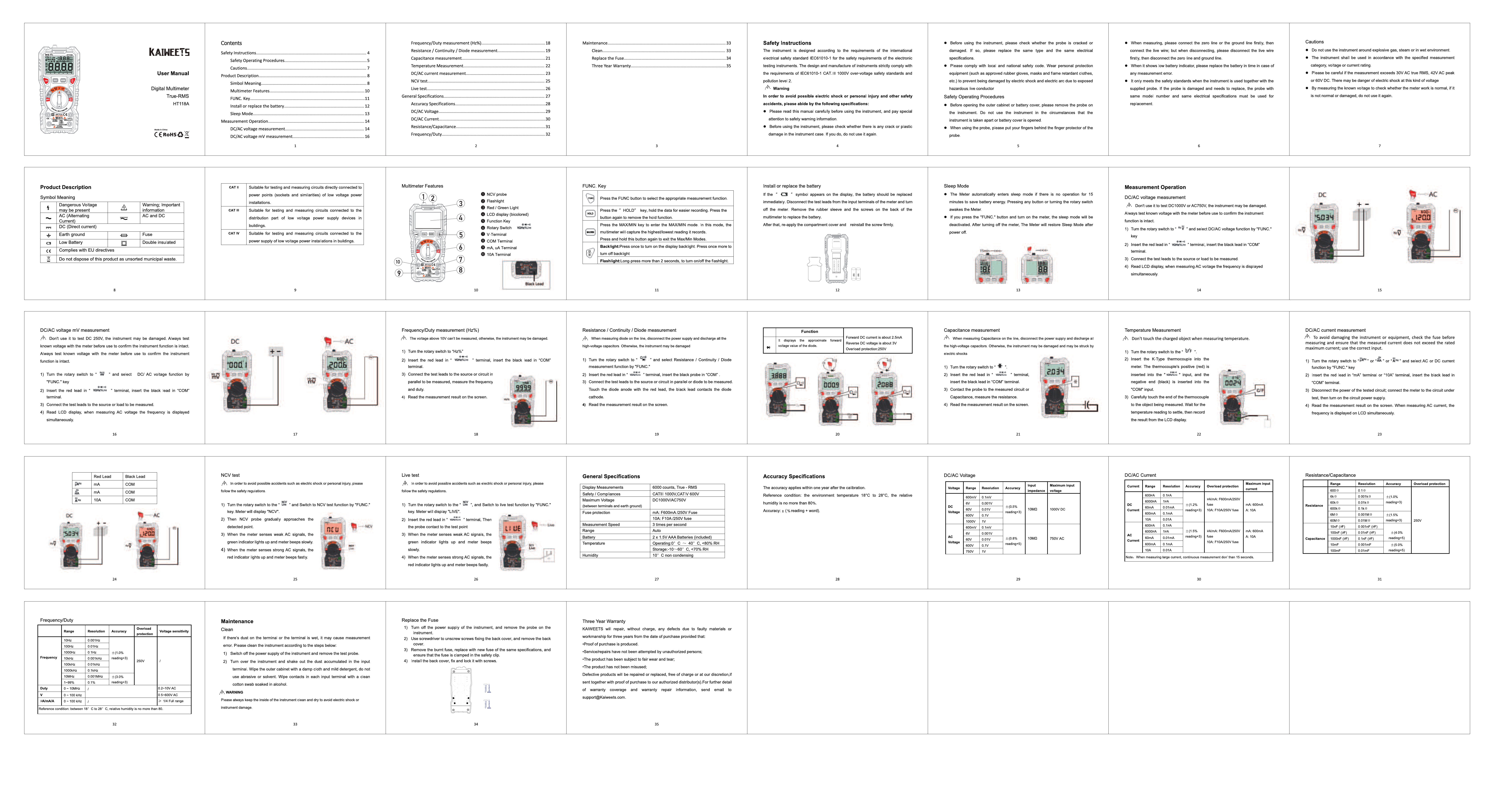
Multimeter Features
- 1: NCV probe
- 2: Flashlight
- 3: Backlight / HOLD button
- 4: LCD display (backlit)
- 5: Function Key
- 6: Rotary Switch
- 7: VΩmA Terminal
- 8: COM Terminal
- 9: mA Terminal
- 10: 10A Terminal
Measurement Operation
DC/AC voltage measurement
A Don't use it to test DC 250V, the instrument may be damaged. Always test known voltage with the meter before use to confirm the instrument function is intact.
- Turn the rotary switch to "V" and select DC/AC voltage function by "FUNC." key.
- Insert the red lead in "VΩmA" terminal, insert the black lead in "COM" terminal.
- Connect the test leads to the source or load to be measured.
- Read LCD display, when measuring AC voltage the frequency is displayed simultaneously.
DC/AC voltage measurement mV
A Don't use it to test DC 250V, the instrument may be damaged. Always test known voltage with the meter before use to confirm the instrument function is intact.
- Turn the rotary switch to "mV" and select DC/AC voltage function by "FUNC." key.
- Insert the red lead in "VΩmA" terminal, insert the black lead in "COM" terminal.
- Connect the test leads to the source or load to be measured.
- Read LCD display, when measuring AC voltage the frequency is displayed simultaneously.
Frequency/Duty measurement (Hz%)
A The voltage above 10V can't be measured, otherwise, the instrument may be damaged.
- Turn the rotary switch to "Hz%".
- Insert the red lead in "VΩmA" terminal, insert the black lead in "COM" terminal.
- Connect the test leads to the source or circuit in parallel to be measured, measure the frequency and duty.
- Read the measurement result on the screen.
Resistance / Continuity / Diode Measurement
A When measuring voltage on the line, disconnect the power supply and discharge all the high-voltage capacitors. Otherwise, the instrument may be damaged by shock.
- Turn the rotary switch to "Ω" and select Resistance / Continuity / Diode measurement function by "FUNC."
- Insert the red lead in "VΩmA" terminal, insert the black probe in "COM" terminal.
- Connect the test leads to the source or circuit in parallel or diode to be measured.
- Read the measurement result on the screen.
Capacitance Measurement
A When measuring Capacitance on the line, disconnect the power supply and discharge all the high-voltage capacitors. Otherwise, the instrument may be damaged and may be struck by electric shocks.
- Turn the rotary switch to "F".
- Insert the red lead into "VΩmA" terminal, insert the black lead into "COM" terminal.
- Connect the probe to the measured circuit or Capacitance, measure the resistance.
- Read the measurement result on the screen.
Temperature Measurement
A Don't touch the charged object when measuring temperature.
- Turn the rotary switch to "°C/°F".
- Insert the K-Type thermocouple into the meter. The thermocouple's positive (red) is inserted into the "VΩmA" terminal, insert the black (negative) into the "COM" input.
- Carefully touch the end of the thermocouple to the object being measured. Wait for the temperature reading to settle, then record the result from the LCD display.
DC/AC current measurement
A To avoid damaging the instrument or equipment, check the fuse before measurement. Ensure that the measured current does not exceed the rated maximum current; use the correct input.
- Turn the rotary switch to "A" or "mA" and select AC or DC current function by "FUNC." key.
- Insert the red lead in "mA" terminal or "10A" terminal, insert the black lead in "COM" terminal.
- Disconnect the power of the tested circuit, connect the meter to the circuit under test, then turn on the circuit power supply.
- Read the measurement result on the screen. When measuring AC current, the frequency is displayed on LCD simultaneously.
NCV Test
A In order to avoid possible accidents such as electric shock or personal injury, please follow the safety regulations.
- Turn the rotary switch to "NCV" and Switch to test NCV function by "FUNC." key. Meter will display "LIVE".
- The NCV probe generally approaches the detection point.
- When the meter senses weak AC signals, the green indicator lights up and meter beeps slowly.
- When the meter senses strong AC signals, the red indicator lights up and meter beeps fastly.
Live Test
A In order to avoid possible accidents such as electric shock or personal injury, please follow the safety regulations.
- Turn the rotary switch to "LIVE" and Switch to test NCV function by "FUNC." key. Meter will display "LIVE".
- Insert the red lead to the "LIVE" terminal, then the black probe is in "COM" terminal.
- When the meter senses weak AC signals, the green indicator lights up and meter beeps slowly.
- When the meter senses strong AC signals, the red indicator lights up and meter beeps fastly.
Maintenance
Clean
If there's dust on the terminal or the terminal is wet, it may cause measurement error. Please clean the instrument according to the steps below:
- Switch off the power supply of the instrument and remove the test probe.
- Turn over the instrument and shake out the dust accumulated in the input terminal. Wipe the outer cabinet with a damp cloth and mild detergent, do not use corrosive or abrasive solvents. Wipe contacts in each input terminal with a clean cotton swabs soaked in alcohol.
Replace the Fuse
If the fuse is damaged due to overload protection, the instrument may be damaged. If the fuse is damaged due to overload protection, the instrument may be damaged.
- Turn off the power supply of the instrument, and remove the probe on the instrument.
- Unscrew driver to unscrew screws fixing the back cover, and remove the back cover.
- Remove the burnt fuse, replace with new fuse of the same specifications, and install back cover, fix and lock it with screws.
General Specifications
| Display Measurements | 6000 counts, True - RMS |
|---|---|
| Safety / Compliances | CATII 1000V CATIII 600V |
| Input Impedance | 10MΩ |
| Fuse protection | mA F600mA/250V Fuse 10A F10A/250V Fuse |
| Measurement Speed | 3 times per second |
| Range | Auto |
| Current | 60mA, 10A AAA Batteries (included) |
| Temperature | Operating: 0°C ~ 40°C, <45% RH Storage: -10°C ~ 60°C, <70% RH |
| Humidity | 10°C non condensing |
Accuracy Specifications
The accuracy applies within one year after the calibration. Reference condition: the environment temperature 18°C to 28°C, the relative humidity is no more than 80%.
Accuracy: ± (% reading + digit)
| Voltage | Range | Resolution | Accuracy | Input Impedance | Maximum Input Voltage |
|---|---|---|---|---|---|
| DC Voltage | 600mV | 0.1mV | ±(1.0%+3) | 10MΩ | 1000V DC |
| 6V | 0.001V | ±(0.5%+3) | |||
| 600V | 0.1V | ±(0.5%+3) | |||
| AC Voltage | 600mV | 0.1mV | ±(1.5%+5) (reading=5) | 10MΩ | 750V AC |
| 6V | 0.001V | ±(1.5%+5) (reading=5) | |||
| 600V | 0.1V | ±(1.5%+5) (reading=5) |
| Current | Range | Resolution | Accuracy | Overload protection | Maximum input current |
|---|---|---|---|---|---|
| DC Current | 60mA | 0.01mA | ±(1.2%+5) | F600mA/250V Fuse | 600mA |
| 600mA | 0.1mA | ±(1.2%+5) | |||
| 10A | 0.01A | ±(2.0%+5) | |||
| AC Current | 60mA | 0.01mA | ±(1.5%+5) (reading=5) | F10A/250V Fuse | 10A |
| 600mA | 0.1mA | ±(1.5%+5) (reading=5) | |||
| 10A | 0.01A | ±(2.0%+5) (reading=5) |
| Resistance | Range | Resolution | Accuracy | Overload protection |
|---|---|---|---|---|
| 600Ω | 0.1Ω | ±(1.0%+3) | 250V | |
| 6kΩ | 1Ω | ±(1.0%+3) | ||
| 60kΩ | 10Ω | ±(1.0%+3) | ||
| 600kΩ | 100Ω | ±(1.0%+3) | ||
| 6MΩ | 1kΩ | ±(1.5%+5) | ||
| 60MΩ | 10kΩ | ±(1.5%+5) | ||
| Capacitance | Range | Resolution | Accuracy | Overload protection |
| 6nF | 1nF | ±(5%+10) | 250V | |
| 60nF | 10nF | ±(5%+10) | ||
| 600nF | 100nF | ±(5%+10) | ||
| 6μF | 1μF | ±(5%+10) | ||
| 60μF | 10μF | ±(5%+10) | ||
| 600μF | 100μF | ±(5%+10) | ||
| 6mF | 1mF | ±(5%+10) |
Note: When measuring large current, continuous measurement don't than 15 seconds.
Three Year Warranty
KAIWEETS warrants its products, without charge, for any defects in materials or workmanship for three years from the date of purchase provided that proof of purchase is produced.
Service/repairs have not been attempted by unauthorized persons;
The product has been subject to fair wear and tear;
The product has not been misused.
Defective products will be repaired or replaced, free of charge or at our discretion, if sent together with proof of purchase to our authorized distributor(s). For further detail of warranty coverage and warranty repair information, send email to support@Kaiweets.com.
