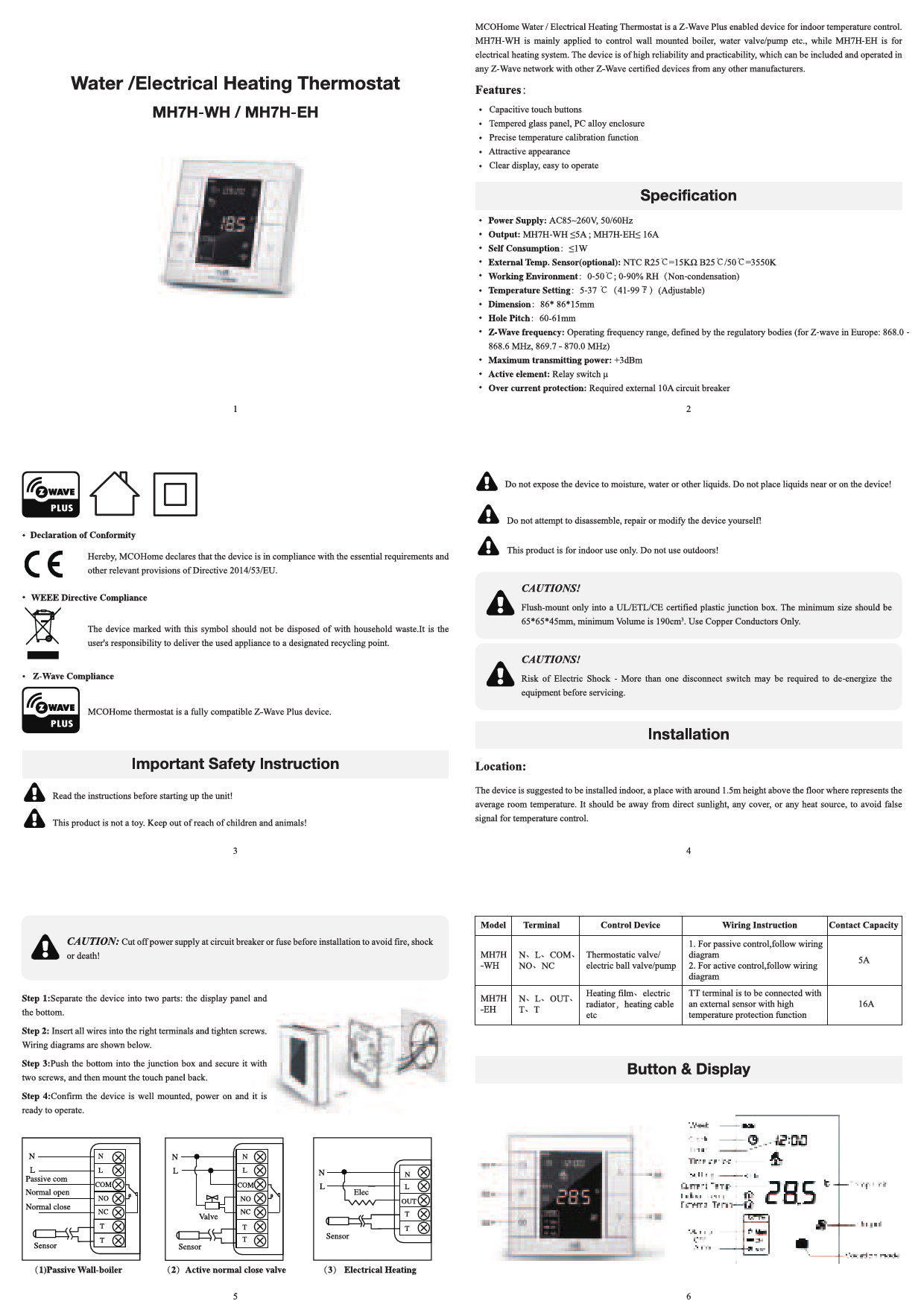
MCOHome MH7H-WH / MH7H-EH Water / Electrical Heating Thermostat
Overview
The MCOHome Water / Electrical Heating Thermostat is a Z-Wave Plus enabled device designed for indoor temperature control. The MH7H-WH model is primarily used for controlling wall-mounted boilers, water valves, or pumps, while the MH7H-EH is designed for electrical heating systems. This device offers high reliability and practicality, allowing it to be included and operated within any Z-Wave network alongside other Z-Wave certified devices from various manufacturers.
Features
- Capacitive touch buttons
- Tempered glass panel, PC alloy enclosure
- Precise temperature calibration function
- Attractive appearance
- Clear display, easy to operate
Specifications
- Power Supply
- AC85~260V, 50/60Hz
- Output
- MH7H-WH ≤5A; MH7H-EH ≤ 16A
- Self Consumption
- ≤1W
- External Temp. Sensor (optional)
- NTC R25°C=15kΩ B25°C/50°C=3550K
- Working Environment
- 0-50°C; 0-90% RH (Non-condensation)
- Temperature Setting
- 5-37°C (41-99°F) (Adjustable)
- Dimension
- 86*86*15mm
- Hole Pitch
- 60-61mm
- Z-Wave frequency
- Operating frequency range, defined by regulatory bodies (for Z-wave in Europe: 868.0 - 868.6 MHz, 869.7-870.0 MHz)
- Maximum transmitting power
- +3dBm
- Active element
- Relay switch μ
- Over current protection
- Required external 10A circuit breaker
Important Safety Instructions & Warnings
⚠️ Caution: Do not expose the device to moisture, water, or other liquids. Do not place liquids near or on the device!
?️❌ Caution: Do not attempt to disassemble, repair, or modify the device yourself!
? Caution: This product is for indoor use only. Do not use outdoors!
Declaration of Conformity: MCOHome declares that the device complies with essential requirements and other provisions of Directive 2014/53/EU.
WEEE Directive Compliance: The device marked with this symbol ♻️ should not be disposed of with household waste. Users are responsible for delivering used appliances to designated recycling points.
Z-Wave Compliance: MCOHome thermostat is a fully compatible Z-Wave Plus device.
Important Safety Instruction: Read the instructions before starting up the unit!
❗ Caution: This product is not a toy. Keep out of reach of children and animals!
Installation Caution: ⚠️ Cut off power supply at circuit breaker or fuse before installation to avoid fire, shock, or death!
Junction Box Requirements: Flush-mount only into a UL/ETL/CE certified plastic junction box. Minimum size: 65*65*45mm, minimum Volume: 190cm³. Use Copper Conductors Only.
Electrical Shock Risk: More than one disconnect switch may be required to de-energize the equipment before servicing.
Installation
Location
The device is suggested to be installed indoors, approximately 1.5m height above the floor, representing the average room temperature. It should be away from direct sunlight, any cover, or heat sources to avoid false temperature readings.
Steps
- Separate the device into two parts: the display panel and the bottom.
- Insert all wires into the correct terminals and tighten screws. Wiring diagrams are provided below.
- Push the bottom into the junction box and secure it with two screws, then mount the touch panel back.
- Confirm the device is well mounted, power it on, and it is ready to operate.
Wiring Diagrams
| Model | Terminal | Control Device | Wiring Instruction | Contact Capacity |
|---|---|---|---|---|
| MH7H-WH | N, L, COM, NO, NC | Thermostatic valve / electric ball valve/pump | 1. For passive control, follow wiring diagram 2. For active control, follow wiring diagram | 5A |
| MH7H-EH | N, L, OUT, T, T | Heating films / electric radiator, heating cable etc | TT terminal is to be connected with an external sensor with high temperature protection function | 16A |
Diagram Descriptions:
- (1) Passive Wall-boiler wiring
- (2) Active normal close valve wiring
- (3) Electrical Heating wiring
Button & Display Overview
The device features a display showing Week, Clock, Time, Time period, Current Temp, Setting Temp, Indoor Temp, External Temp, and Temp Unit. Buttons include S1-S5 for navigation and control. The display also indicates Output status (Manual/Auto/Off) and Vocation mode.
Visual Description: The display shows current time (e.g., 12:00), current temperature (e.g., 28.5°C), and various mode indicators. Buttons are labeled S1 through S4, and S5. There are also indicators for System, Manual, Auto, and Vocation mode.
Operation
On/Off Operation
When powered on, the device displays "OFF". Pressing the S3 button switches between manual, off, and auto modes. Press S2 to confirm. After powering on, the device shows the current week, local time, working mode, temperature, and output status. Note: After the backlight dims, press a button to wake it up before performing operations.
Temperature Setting
In normal working status, press S4 or S5 to enter the temperature setting interface. The adjustable range is 5-37°C (41-99°F). Use S4 or S5 to adjust the value. Press S3 or wait 25 seconds without key operation to save and return to the normal interface.
- Auto Mode: The changed value is only valid for the current time period and does not affect preset time period values.
- Manual Mode: The changed value is valid until the next setting.
- Vacation Mode: The changed value is valid until the next setting.
Key Lock Function
In the normal operating interface, long-press S1+S4 simultaneously to lock the buttons. A lock icon ? will appear, disabling all buttons. Long-press S1+S4 again to unlock, and the icon ? will disappear, restoring normal button functionality.
Control Specification (MH7H-WH)
- Detection temperature < setting temperature - 0.5°C: output turns on, and output icon displays.
- Detection temperature ≥ setting temperature + 0.5°C: output turns off, and output icon disappears.
Control Specification (MH7H-EH)
- Detection temperature < setting temperature - 1.5°C: output turns on, and output icon displays.
- Detection temperature ≥ setting temperature: output turns off, and output icon disappears.
Manual / Auto Mode Setting
From the normal display interface, touch S3 to switch between Manual and Auto modes. Select the desired mode and press S2 to save.
- Auto Mode: The device automatically controls the heating system based on preset time periods and temperatures.
- Manual Mode: The device follows the manually set temperature for heating control.
Vacation Mode Setting
From the normal working interface, long-press S2 to enter vacation mode temperature setting (default 10°C, range 5-37°C / 41-98°F). Use S4 or S5 to adjust, then press S3 or wait 25 seconds to save. The vacation mode icon will display. Long-press S2 again to end vacation mode.
Local Time Setting
From the normal working interface, long-press S1 to enter the local time setting interface. Use S4 or S5 to set "week, hour & minute", and press S1 to switch between these parameters. Press S1 or wait 25 seconds to save and return to the normal display.
Auto Mode Time Periods Parameter Setting
Short-press S1 from the normal working interface to enter time periods setting. Four time periods can be set daily for the entire week. Use S2 to switch between "Hours, Minutes, Temperature value", and S4 or S5 to change values. After setting Monday's periods, press S1 to proceed to the next day. Press S1/S2 or wait 25 seconds to save and return to normal display.
Default Settings:
| Week Periods | Period 1 | Period 2 | Period 3 | Period 4 |
|---|---|---|---|---|
| Mon~Fri | 5:00 28°C | 7:00 24°C | 17:00 28°C | 22:00 24°C |
| Sat-Sun | 5:00 28°C | 9:00 24°C | 17:00 28°C | 22:00 24°C |
High Temperature Protection (For MH7H-EH Electrical Heating ONLY)
When the external temperature sensor detects ≥55°C, high temperature protection is activated, and the electric heating is forced off. A high temperature protection icon will display. When the external temperature sensor detects <50°C, the device returns to normal work, and the icon disappears.
Anti-Freeze Protection Function: (Optional)
In shutdown interface:
- When the built-in temperature sensor detects ≤5°C, anti-freeze protection is activated, electric heating is forced on, and the anti-freeze protection icon displays.
- When the built-in temperature sensor detects >8°C, anti-freeze protection is deactivated, and the icon disappears.
Note: If no external temperature sensor is connected, only the indoor temperature icon is displayed. With an external sensor, both indoor and external temperatures are shown. The high temperature protection icon flickers when active.
Humidity Display Operation
In the normal working interface, long-press S1+S5 buttons to enter the humidity display interface. Press S1+S5 again to return to the normal interface.
Z-Wave Operation
Including & Excluding from Z-Wave Network
Press and hold S4 in the normal working interface to enter the inclusion/exclusion interface. Before inclusion, "- - -" is displayed. Press S4 once to enter learning mode and obtain a Node ID. A successful inclusion displays the Node ID. A Node ID confirms the device is in the network.
Follow the same steps to exclude the device. Exclusion restores the device to its Z-Wave factory settings.
Visual Description: The screen shows "007" after inclusion, indicating Node ID. Before inclusion, it shows "- - -".
Note: After inclusion, turn the device off and then on. It is now ready to be operated by a Z-Wave controller/gateway.
Association Group
| AG Identifier | Max Node ID | Command Class | Trigger Situation |
|---|---|---|---|
| 1 | 5 | COMMAND_CLASS_DEVICE_RESET_LOCALLY, COMMAND_CLASS_SENSOR_MULTILEVEL V5, SENSOR_MULTILEVEL_REPORT_V5 | 255 parameter setting value 85 1. When parameter set to 1, the amount of temperature change is greater than the parameter setting value of No. 2, or the humidity change is greater than the parameter setting value of No. 5. 2. When parameter set to 2, the time interval is greater than the setting value of parameter No. 4. 3. When parameter set to 3, the temperature change amount is greater than the parameter setting value of No. 2, or the humidity change is greater than the parameter setting value of No. 5, or the time interval is greater than the setting value of parameter No. 4. |
| 2 | 5 | COMMAND_CLASS_THERMOSTAT_MODE_V2, THERMOSTAT_MODE_REPORT | Device mode change |
| 3 | 5 | COMMAND_CLASS_THERMOSTAT_OPERATING_STATE, THERMOSTAT_OPERATING_STATE_REPORT | Device status change |
| 5 | 5 | COMMAND_CLASS_THERMOSTAT_SETPOINT_V2, THERMOSTAT_SETPOINT_REPORT_V2 | Device mode set point change |
| 3 | 5 | COMMAND_CLASS_BASIC, BASIC_SET | Device status change |
| 3 | 5 | COMMAND_CLASS_BASIC, BASIC_SET | Device status change |
Device Command Classes
The device supports the following Z-Wave Command Classes:
- COMMAND_CLASS_ZWAVEPLUS_INFO
- COMMAND_CLASS_POWERLEVEL
- COMMAND_CLASS_VERSION
- COMMAND_CLASS_DEVICE_RESET_LOCALLY
- COMMAND_CLASS_MANUFACTURER_SPECIFIC
- COMMAND_CLASS_BASIC
- COMMAND_CLASS_THERMOSTAT_SETPΟΙΝΤ
- COMMAND_CLASS_THERMOSTAT_MODE
- COMMAND_CLASS_THERMOSTAT_OPERATING_STATE
- COMMAND_CLASS_SENSOR_MULTILEVEL
- COMMAND_CLASS_TIME
- COMMAND_CLASS_TIME_PARAMETERS
- COMMAND_CLASS_ASSOCIATION
- COMMAND_CLASS_ASSOCIATION_GRP_INFO
- COMMAND_CLASS_MANUFACTURER_SPECIFIC
- COMMAND_CLASS_CONFIGURATION
- COMMAND_CLASS_FIRMWARE_UPDATE_MD_V2
Secret Menu & Parameter Settings
Secret Menu Access
In shutdown state, long-press S3+S5 simultaneously to enter the secret menu. Press S4 to choose a number and S3 to switch among numbers (code: 1234). After "1234" is displayed, press S2 to enter the parameter setting interface. Use S4 or S5 to adjust the current parameter, and S2 to switch among items.
Parameter Settings
| Item | Function | Default | Range | Remark |
|---|---|---|---|---|
| P01 | Temp. Setting Upper Limit | 37.0°C (99°F) | 00-99.5°C (32-211°F) | Always confirm the upper limit > bottom limit |
| P02 | Temp. Setting Bottom Limit | 5°C (41°F) | 00-99.5°C (32-211°F) | |
| P03 | Slave Address | 1 | 1~64 | Reserved |
| P04 | Time Format | 24 | 12/24 | hours |
| P05 | EH Negative Hysteresis | 1.5°C (3°F) | 0.0-10.0°C (0-18°F) | |
| P05 | WH Negative Hysteresis | 0.5°C (1°F) | 0.0-10.0°C (0-18°F) | |
| P06 | EH Positive Hysteresis | 1.5°C (3°F) | 0.0-10.0°C (0-18°F) | |
| P06 | WH Positive Hysteresis | 0.5°C (1°F) | 0.0-10.0°C (0-18°F) | |
| P07 | Anti-Freeze Temperature Setting | 5°C (41°F) | 0-30°C (32-86°F) | |
| P08 | Protection Temperature | 55°C (131°F) | 25-95°C (77-203°F) | MH7H-EH / MH7H-EH-WT15 |
| P09 | Power On State After Power Failure | OFF | OFF/OPN/PRU | OFF: device turn to OFF state, OPN: device turn to ON state, PRU: device return to last state |
| P10 | The Time Of Temperature Change | 2 | 0-99 | 2*30s-1min |
| P11 | Indoor Temperature Calibration | 0.0°C (00°F) | -9.5-9.5°C (-16-16°F) | |
| P12 | Beep Volume | 3 | 0F/0-9 | |
| P13 | Backlit Level | 2 | 1-8/ON/OFF | |
| P14 | Outdoor Temperature Calibration | 0.0°C (00°F) | -9.5-9.5°C (-16-16°F) | |
| P15 | Control Based On External Temperature | ON | ON/OFF | MH7H-WH, MH7H-EH |
| P15 | Control Based On External Temperature | ON | ON/OFF | MH7H-WH-WT15, MH7H-EH-WT15 |
| P16 | Display Based On External Temperature | OFF | ON/OFF | MH7H-WH, MH7H-EH |
| P16 | Display Based On External Temperature | OFF | ON/OFF | MH7H-WH-WT15, MH7H-EH-WT15 |
| P17 | Temp. Format | °C | °C/°F | °C: Celsius; °F: Fahrenheit |
| P18 | Restore Factory Setting | Display:53 Password: 55 | 00-99 | Change 53 to 55, and press S3 to confirm. |
| P19 | High Temp. Protection Hysteresis Setting | 5°C (41°F) | 1-10°C (2-18°F) |
After Power Failure Behavior
- 0: Device will be in shutdown state ("OFF") when power on again.
- 1: Device will be in working interface when power on again.
- 2 (default): Device will stay the status before power failure when power on again.
1-Year Limited Warranty
MCOHome warrants this product to be free from defects in material and workmanship under normal and proper use for one year from the purchase date for the original purchaser. MCOHome will, at its option, repair or replace any part of its products that prove defective due to improper workmanship or materials. This limited warranty does not cover any damage to this product that results from improper installation, accident, abuse, misuse, natural disaster, insufficient or excessive electrical supply, abnormal mechanical or environmental conditions, or any unauthorized disassembly, repair, or modification. This limited warranty shall not apply if: (i) the product was not used in accordance with any accompanying instructions, or (ii) the product was not used for its intended function. This limited warranty also does not apply to any product on which the original identification information has been altered, obliterated, or removed, that has not been handled or packaged correctly, that has been sold as second-hand, or that has been resold contrary to applicable export regulations.
