CSP-3000
File info: application/pdf · 10 pages · 9.99MB
CSP-3000
3000W Power Supply with Single Output CSP-3000
Function Manual ※ Mode Setting 1. Output Voltage/Current Programming In the PC mode, the adjustable resistor (SVR2) can set the maximum constant current point. 3000W Power Supply with Single Output CSP-3000 series O U T…
Full PDF Document

If the inline viewer fails, it will open the original document in compatibility mode automatically. You can also open the file directly.
Extracted Text
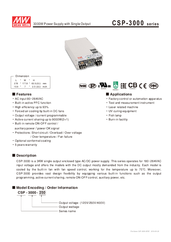
3000W Power Supply with Single Output

CSP-3000 series

Dimension
L *W* H 278 * 177.8 * 63.5 (2U) mm 10.9 * 7 * 2.5 (2U) inch
 Features �AC input 80~264VAC �Built-in active PFC function �High efficiency up to 93% �Forced air cooling by built-in DC fans �Output voltage / current programmable �Active current sharing up to 9000W(2+1) �Built-in remote ON-OFF control /
auxiliary power / power OK signal �Protections: Short circuit / Overload / Over voltage
/ Over temperature / Fan failure
�Optional conformal coating �5 years warranty

UL62368-1

EN62368-1

IEC62368-1

 Applications

�Factory control or automation apparatus

�Test and measurement instrument

�Laser related machine

�UV curing equipment

�Fish lamp

�Burn-in facility

 Description
CSP-3000 is a 3KW single output enclosed type AC/DC power supply. This series operates for 180~264VAC input voltage and offers the models with the DC output mostly demanded from the industry. Each model is cooled by the built-in fan with fan speed control, working for the temperature up to 70. Moreover, CSP-3000 provides vast design flexibility by equipping various built-in functions such as the output programming, active current sharing, remote ON-OFF control, auxiliary power, etc.
 Model Encoding / Order Information CSP - 3000 - 250

Output voltage (120V/250V/400V) Output wattage Series name

File Name:CSP-3000-SPEC 2019-06-28

3000W Power Supply with Single Output

CSP-3000 series

SPECIFICATION

MODEL

CSP-3000-120

CSP-3000-250

CSP-3000-400

DC VOLTAGE

120V

250V

400V

RATED CURRENT

25A

12A

7.5A

CURRENT RANGE

0 ~ 25A

0 ~ 12A

0 ~ 7.5A

RATED POWER

3000W

3000W

3000W

RIPPLE & NOISE (max.) Note.2 800mVp-p

1000mVp-p

1200mVp-p

OUTPUT

CONSTANT CURRENT REGION 90 ~ 120V

VOLTAGE TOLERANCE Note.3 �1.0%

LINE REGULATION

�0.5%

LOAD REGULATION

�0.5%

125 ~ 250V �1.0% �0.5% �0.5%

200 ~ 400V �1.0% �0.5% �0.5%

SETUP, RISE TIME

1000ms, 80ms / 230VAC at full load

HOLD UP TIME (Typ.)

10ms at full load

VOLTAGE RANGE Note.4 180 ~ 264VAC 254 ~ 370VDC

FREQUENCY RANGE

47~63Hz

POWER FACTOR (Typ.)

PF0.95/230VAC at full load

INPUT EFFICIENCY (Typ.)

92%

92.5%

93%

AC CURRENT (Typ.)

20A/180VAC 16A/230VAC

INRUSH CURRENT (Typ.) Cold start 60A/230VAC

LEAKAGE CURRENT

<0.3mA / 240VAC

SHORT CIRCUIT

Shut down and latch off o/p voltage, re-power on to recover

OVER CURRENT PROTECTION
OVER VOLTAGE
OVER TEMPERATURE OUTPUT VOLTAGE PROGRAMMABLE(PV)

105 ~ 120% rated output power

Constant current limiting with delay shutdown after 3 seconds, re-power to recover

127 ~ 150V

265 ~ 315V

420 ~ 500V

Protection type : Shut down o/p voltage, re-power on to recover

Shut down o/p voltage, recovers automatically after temperature goes down or re-power on to recover

24 ~ 120V

50 ~ 250V

80 ~ 400V

Please refer to the Function Manual.

CURRENT SHARING FUNCTION
AUXILIARY POWER(AUX)

Please refer to the Function Manual. 12V@0.4A

REMOTE ON-OFF CONTROL Please refer to the Function Manual

ALARM SIGNAL OUTPUT WORKING TEMP.

Power OK signal. Please refer to the Function Manual -20 ~ +60 (Refer to "Derating Curve")

WORKING HUMIDITY

20 ~ 90% RH non-condensing

ENVIRONMENT STORAGE TEMP., HUMIDITY -40 ~ +85, 10 ~ 95% RH non-condensing

TEMP. COEFFICIENT

�0.05%/ (0 ~ 50)

VIBRATION

10 ~ 500Hz, 2G 10min./1cycle, 60min. each along X, Y, Z axes

SAFETY STANDARDS

UL62368-1,Dekra seal EN62368-1, EAC TP TC004, GB4943.1

WITHSTAND VOLTAGE

I/P-O/P:3KVAC I/P-FG:2KVAC O/P-FG:0.5KVAC

ISOLATION RESISTANCE I/P-O/P, I/P-FG, O/P-FG:100M Ohms / 500VDC / 25/ 70% RH

Parameter

Standard

Test Level / Note

Conducted

EN55032(CISPR32)/EN55011(CISPR11) Class A

EMC EMISSION

Radiated Harmonic Current

EN55032(CISPR32)/EN55011(CISPR11) Class A

EN61000-3-2

-----

SAFETY &
EMC (Note 5)

Voltage Flicker EN55024 , EN61204-3, EN61000-6-2 Parameter ESD

EN61000-3-3
Standard EN61000-4-2

-----
Test Level / Note Level 3, 8KV air ; Level 2, 4KV contact

Radiated

EN61000-4-3

Level 3

EMC IMMUNITY

EFT / Burst Surge

EN61000-4-4 EN61000-4-5

Level 3 Level 3, 2KV/Line-Earth ; Level 2, 1KV/Line-Line

Conducted

EN61000-4-6

Level 3

Magnetic Field

EN61000-4-8

Level 4

OTHERS NOTE

Voltage Dips and Interruptions

EN61000-4-11

>95% dip 0.5 periods, 30% dip 25 periods, >95% interruptions 250 periods

MTBF

223.8K hrs min. Telcordia SR-332 (Bellcore) ; 75.1K hrs min. MIL-HDBK-217F (25)

DIMENSION

278*177.8*63.5mm (L*W*H)

PACKING

4Kg; 4pcs/16Kg/1.81CUFT

1. All parameters NOT specially mentioned are measured at 230VAC input, rated load and 25 of ambient temperature.

2. In the PV Mode: Ripple & noise are measured at 20MHz of bandwidth by using a 12" twisted pair-wire terminated with a 0.1uf & 47uf parallel capacitor.

3. Tolerance : includes set up tolerance, line regulation and load regulation.

4. Turn off the output when input voltage is less than 160VAC.

5. The power supply is considered a component which will be installed into a final equipment. All the EMC tests are been executed by mounting the unit on  a 720mm*360mm metal plate with 1mm of thickness. The final equipment must be re-confirmed that it still meets EMC directives. For guidance on how to

perform these EMC tests, please refer to "EMI testing of component power supplies." (as available on http://www.meanwell.com) 6. The ambient temperature derating of 3.5/1000m with fanless models and of 5/1000m with fan models for operating altitude higher than 2000m(6500ft).

File Name:CSP-3000-SPEC 2019-06-28

3000W Power Supply with Single Output

CSP-3000 series

Block Diagram
EMI I/P
FILTER

ACTIVE INRUSH
CURRENT LIMITING

RECTIFIERS & PFC

POWER SWITCHING

RECTIFIERS &
FILTER

PFC CONTROL
O.T.P.

O.L.P.
PWM CONTROL

LOAD SHARING
FAN AUX POWER

O.V.P.
DETECTION CIRCUIT REMOTE CONTROL
RECTIFIERS &
FILTER

PFC fosc : 85KHz PWM fosc : 100KHz
+V -V
P OK RC CS AUX POWER (12V/0.4A)

LOAD (%)

Static Characteristics

Derating Curve

100 90 80 70 60 50 40

180

190

200

210

220

250 264

INPUT VOLTAGE (V) 60Hz

LOAD (%)

100
80
60 50 40
20

-20

0

10

20

30

40

50 60 65 70 (HORIZONTAL)

AMBIENT TEMPERATURE ()

Efficiency vs Load (400V Model)
94 92 90 88 86 84 82 80 78
10% 20% 30% 40% 50% 60% 70% 80% 90% 100%
LOAD
 The curve above is measured at 230VAC.

File Name:CSP-3000-SPEC 2019-06-28

EFFICIENCY (%)

3000W Power Supply with Single Output

CSP-3000 series

DRIVING METHODS OF LED MODULE
 I-V Operating Area   CSP-3000-120

130V

125V
2.4A, 120V 120V

115V

110V

105V

100V

95V

90V 2.4A, 90V
85V

80V

0A

5A

15A,120V
10A 15A 20A

25A, 120V
30A, 100V 30A, 90V 25A 30A 35A

Recommended High Performance Region

Allowed Operational Region

 CSP-3000-250

260V 1.36A, 250V
240V

220V

200V

180V

160V

140V

120V 1.36A, 125V

100V

0A

3A

9A,250V

12A, 250V

6A

9A

12A

15A

17A, 176.5V 17A, 125V 18A

Recommended High Performance Region

Allowed Operational Region

 CSP-3000-400

430V 0.8A, 400V 5.25A,400V 7.5A, 400V
400V

370V

340V 10A, 300V
310V

280V

250V

220V

190V
0.8A, 200V 160V

10A, 200V

130V

100V

0A 1.5A 3A 4.5A 6A 7.5A 9A 10.5A 12A 13.5A 15A

Recommended High Performance Region

Allowed Operational Region

File Name:CSP-3000-SPEC 2019-06-28

3000W Power Supply with Single Output

Function Manual
1. Output Voltage/Current Programming  Mode Setting
CN1:

CONDITION MODE

FUNCTION

PIN5/PIN6

SHORT OPEN

PV MODE Output Voltage Programming PC MODE Output Current Programming

CSP-3000 series

OUTPUT VOLTAGE SET (%)

PIN6 PIN5 PV/PC MODE CHOSE
CN1
PV/PC SET(SVR2)
max.

PIN8

PIN7 PV/PC SET

PIN6

PIN5 PV/PC ADJUST

CN2

 PV/PC Set adjustment  In the PV mode, the adjustable resistor (SVR2) can set the output voltage, the output voltage can be adjusted to 20-100% of the rated voltage.  In the PV mode, the pin7/pin8 at the CN2 terminal only accepts the input DC voltage to set the output voltage, and the output voltage can be trimmed to 20-100% of the rated voltage.  When pin7/pin8 signal<2V,output voltagerated voltage 10%.  In the PC mode, the adjustable resistor (SVR2) can set the maximum constant current point.  In the PC mode, the maximum output constant current value can be set when the pin7/pin8 of the CN2 terminal accepts only the input DC voltage. The output maximum constant current value can be trimmed by the CN2 terminal pin7/pin8 voltage (Vs), the relationship between voltage and current: Imax. *Vs/10V  The adj. min. current8%Imax, refer to PC range.  For fast output response, it is recommended to adjust through CN2 terminal PIN5/PIN6, applying additive 10V PWM signal(frequency range 500Hz~1KHz).

V

100

80

Non-Linear

60

40

MODEL 120V 250V 400V PV Range 24 ~ 120V 50 ~ 250V 80 ~ 400V

20 2

(V)

4

6

8 10

EXTERNAL VOLTAGE (DC)

Vout

OUTPUT CURRENT SET (%)

I

100

80

Non-Linear

60

40

MODEL 120V

250V

400V

PC Range 6 ~ 30A(max.) 3.4~ 17A( max.) 2 ~ 10A(max.)

20 2

(V)

4

6

8 10

EXTERNAL VOLTAGE (DC)

100

80

Non-Linear

60

40

8

0.8

4

6

8 10 V

8

40 60 80 100 %

EXTERNAL VOLTAGE (DC)/PWM

MODEL

120V

250V

400V

PC Range 2.4 ~ 30A( max.) 1.4~ 17A(max.) 0.8 ~ 10A( max.)

File Name:CSP-3000-SPEC 2019-06-28

OUTPUT VOLTAGE / CURRENT ADJ. (%)

3000W Power Supply with Single Output

CSP-3000 series

2.Remote ON-OFF  Remote ON-OFF is activated by the configuration with respect to CN1 as shown in the following diagram.

PIN3 RC PIN1 RCG
CN1

Example 2.2(A): Using external voltage source
Internal 12V typ.

1K

AUX
12V RC
SW RCG

AUXG

Example 2.2(B): Using internal 12V auxiliary output AUX

Internal 12V typ.

1K

RC
RCG SW
AUXG

Example 2.2(C): Using internal 12V auxiliary output

Internal 12V typ.

1K

AUX 1K
RC
SW
RCG

 Connection Method

AUXG

Example 2.2(A) Power supply output ON SW Open(open) SW Logic Power supply output OFF SW Close(short)

Example 2.2(B) SW Open(open) SW Close(short)

Example 2.2(C) SW Close(short) SW Open(open)

File Name:CSP-3000-SPEC 2019-06-28

3000W Power Supply with Single Output

CSP-3000 series

3.Alarm Signal Output  Alarm signal is sent out through "P OK" & "P OK GND" and P OK2 & P OK GND2 pins on CN1. Please acknowledge an external voltage source is required for this function.

PIN9(P-OK-GND) PIN7(P-OK)

PIN4(P-OK-GND-2) PIN2(P-OK-2)
CN1

Function P OK

Description

Output of alarm(P OK, Relay Contact) Output of alarm(P OK2, TTL Signal)

The signal is "Low" when the power supply is above Low 80% of the rated output voltage, or, say, Power OK (0.5V max at 500mA)

Low (0.5V max at 10mA)

The signal turns to be "High" when the power supply

High or open

High or open

is under 80% of the rated output voltage, or, say,

(External applied voltage, 500mA max.) (External applied voltage, 10mA max.)

Power Fail

Table 3.1 Explanation of alarm

P OK

P OK2

R V

0.1uF

R V

P OK GND

External voltage and R (The max. sink is 500mA and 20V)

Fig. 3.2 Internal circuit of P OK (Relay, total is 10W)

P OK GND2

External voltage and R (The max. sink is 10mA and 30V)

Fig. 3.3 Internal circuit of P OK2 (Open collector method)

File Name:CSP-3000-SPEC 2019-06-28

3000W Power Supply with Single Output

CSP-3000 series

4.Current Sharing
CSP-3000 has the built-in active current sharing function and can be connected in parallel, up to 3 units, to provide higher output power as exhibited below :  The power supplies should be paralleled using short and large diameter wiring and then connected to the load.  Difference of output voltages among parallel units should be less than 0.2V(Can Fine tune by SVR1).  The total output current must not exceed the value determined by the following equation:
Maximum output current at parallel operation=(Rated current per unit)�(Number of unit)�0.9  When out current<( 50% rate current)�(Number of unit),
the current shared among units may not be fully balanced.

 CS+/CS- on CN1 are connected mutually in parallel(Note:CS+/CS- do not reverse connection).  Under parallel operation, the "PV/PC" function is not available.

No.1(Master)

Current Sharing condition max. Output Voltage ADJ(SVR1)

No.2(Slave) No.3(Slave)

+V -V
+V -V

+V
Load -V

+V -V

File Name:CSP-3000-SPEC 2019-06-28

3000W Power Supply with Single Output
Mechanical Specification
278 236.3

1
8-M4(Both Sides) L=5mm
4-M4 L=5mm
1

236.3

Air flow direction
1

162

7.9

CSP-3000 series

Case No.982B Unit:mm
27

38 12.5 63.5

1

27

19max.

CN1
10 8 6 4 2
9 7 531

CN2
8642
7531

16 13

1
OUTPUT

177.8

13 10

INPUT
1
16max.

 Mounting Instruction

Hole No. Recommended Screw Size

1

M4

MAX. Penetration Depth L 5mm

Recommended mounting torque 7~10Kgf-cm

 Control Pin No. Assignment (CN1) : FJY 964-20531-180016 or equivalent

9

10

Mating Housing FJY 3521-1000205-1803 or equivalent

Terminal

FJY 256-210000-22119 or equivalent

1

2

 CN1 are connected internally.

Pin No. 1 2 3 4 5 6 7 8 9 10

Function RCG
P-OK-2 RC
P-OK-GND-2 GND Mode P-OK CS+
P-OK GND CS-

Description Remote ON-OFF Ground Power OK Signal(TTL Signal) Remote ON-OFF Power OK Ground PV/PC Mode Choose Ground PV/PC Mode Choose Power OK Signal(Relay Contact) Current Sharing Signal+ Power OK Ground Current Sharing Signal-

Mounting Surface

Chassis of CSP-3000

Mounting Screw L

File Name:CSP-3000-SPEC 2019-06-28

3000W Power Supply with Single Output

Control Pin No. Assignment (CN2) : FJY 964-20431-180016 or equivalent

7

8

1

2

Mating Housing FJY 3521-1000204-1803 or equivalent

Terminal

FJY 256-210000-22119 or equivalent

Pin No. 1 2 3 4 5 6 7 8

Function 12V AUXG 12V AUX+
NC NC PV/PC+ PV/PCSET+ SET-

Description Auxiliary output GND Auxiliary output+
PV/PC adjust+ for fast output response PV/PC adjust- for fast output response PV/PC set+ PV/PC set-

AC Input Terminal Pin No. Assignment

Pin No. Assignment

Diagram

1

AC/L

2

AC/N

3

FG

DC Output Terminal Pin No. Assignment

Pin No. Assignment

Diagram

1

V-

2

V+

Maximum mounting torque 18Kgf-cm
Maximum mounting torque 18Kgf-cm

Installation Manual
Please refer to : http://www.meanwell.com/manual.html

CSP-3000 series

File Name:CSP-3000-SPEC 2019-06-28