CERTIFIED 055-0380-4 3550W Portable Generator Instruction Manual
File info: application/pdf · 52 pages · 8.50MB
3550W PORTABLE GENERATOR
Conta C t Informat I on model no. 055-0380-4 contact us 1-844-428-7277 2 for problems or questions, Do not rEtUrn to StorE. Please contact one of our Customer Service agents who would be happy
[PDF] 3550W PORTABLE GENERATOR - Champion Power Equipment
Do not use electrical cords that are worn, damaged or frayed. Do not operate generator in wet weather. Do not allow children or unqualified persons to operate ...
Full PDF Document

If the inline viewer fails, it will open the original document in compatibility mode automatically. You can also open the file directly.
Extracted Text
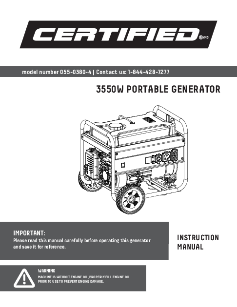
model number 055-0380-4 | Contact us: 1-844-428-7277
3550W PORTABLE GENERATOR

IMPORTANT:
Please read this manual carefully before operating this generator and save it for reference.
WARNING
MACHINE IS WITHOUT ENGINE OIL, PROPERLY FILL ENGINE OIL PRIOR TO USE TO PREVENT ENGINE DAMAGE.

INSTRUCTION MANUAL

CONTACT INFORMATION

2
model no. 055-0380-4 | contact us 1-844-428-7277
For problems or questions, DO NOT RETURN TO STORE. Please contact one of our Customer Service Agents who would be happy to assist you.
For Customer Assistance Please Call:
1-844-428-7277
Read and understand this instruction manual thoroughly before using the product. It contains important information for your safety as well as operating and maintenance advice. Keep this instruction manual for future use. Should this product be passed on to a third party, this instruction manual must be included.

3

TABLE OF CONTENTS

Contact Information....................................................................2 Table of Contents ........................................................................3 Safety Information ......................................................................4
Safety Definitions ...................................................................................4 Fuel Safety............................................................................................... 7 Gasoline and gasoline vapours .............................................................. 7 When adding or removing gasoline........................................................ 7 When starting the generator................................................................. 7 When operating the generator ..............................................................8 When transporting or servicing the generator .....................................8 When storing the generator ..................................................................8 Safety Labels...........................................................................................9 Safety Symbols.......................................................................................10 Operation Symbols ................................................................................. 11 Quick start Label Symbols .....................................................................12 Starting the Engine ..............................................................................12 Stopping the Engine .............................................................................12 Controls and Features ................................................................13 Generator ..............................................................................................13 Control Panel ..........................................................................................14 Digital Info Gauge....................................................................................15 Tools Required.........................................................................................16 Parts Included.........................................................................................16 Accessories ...........................................................................................16 Assembly Parts .....................................................................................16 Assembly.....................................................................................17 Unpacking ............................................................................................. 17 Install the Wheels.................................................................................17 Install the Support Leg.........................................................................18 Install the Handle .................................................................................18 Add Engine Oil .......................................................................................19 Add Fuel ................................................................................................21 Grounding ............................................................................................. 23

Operation ...................................................................................24
Generator Location..............................................................................24 Surge Protection..................................................................................25 Starting the Engine .............................................................................25 Connecting Electrical Loads ...............................................................26 Do Not Overload Generator..................................................................26 Stopping the Engine ............................................................................ 27 Operation at High Altitude..................................................................28 Maintenance ..............................................................................29 Cleaning the Generator .......................................................................29 Changing the Engine Oil.......................................................................30 Cleaning and Adjusting the Spark Plug...............................................30 Cleaning the Air Filter...........................................................................31 Cleaning the Spark Arrestor.................................................................31 Adjusting the Governor ........................................................................31 Maintenance Schedule........................................................................32 Storage....................................................................................... 33 Short Term Storage (up to 30 days)....................................................33 Mid Term Storage (30 days � 1 year) ....................................................33 Long Term Storage (over 1 year) ..........................................................34 Removing from Storage .......................................................................35 Specifications ...........................................................................36 Generator Specifications....................................................................36 Engine Specifications..........................................................................36 Oil Specifications ................................................................................36 Fuel Specifications.............................................................................. 37 Temperature Specifications................................................................ 37 ICES�002 Warning................................................................................ 37 Parts List Diagram .................................................................................38 Parts List................................................................................................39 Engine Parts List Diagram......................................................................42 Parts List................................................................................................43 Wiring Diagram .......................................................................................45 Troubleshooting .........................................................................46 Warranty Information................................................................48 3-Year Limited Warranty.......................................................................48 Additional Limitations...........................................................................49 Notice To Consumer...............................................................................49

SAVE THESE INSTRUCTIONS
This manual contains important safety and operating instructions. Read all instructions and follow them with use of this product.

4
model no. 055-0380-4 | contact us 1-844-428-7277

SAFETY DEFINITIONS
F DANGER DANGER indicates a hazardous situation which, if not avoided, will result in death or serious injury.
F WARNING WARNING indicates a hazardous situation which, if not avoided, could result in death or serious injury.

F CAUTION CAUTION indicates a hazardous situation which, if not avoided, could result in minor or moderate injury.
NOTICE NOTICE is used to address practices not related to physical injury.

SAFETY INFORMATION

DANGER
Generator exhaust contains carbon monoxide, a colourless, odourless, poisonous gas. Breathing carbon monoxide will cause nausea, dizziness, fainting or death. If you start to feel dizzy or weak, get to fresh air immediately. OPERATE GENERATOR OUTDOORS ONLY IN A WELL VENTILATED AREA AND POINT EXHAUST AWAY. DO NOT operate the generator inside any building, including garages, basements, crawlspaces and sheds, enclosures or compartments, including the generator compartment of a recreational vehicle. DO NOT allow exhaust fumes to enter a confined area through windows, doors, vents or other openings.
DANGER
Using a generator indoors can kill you in minutes. Generator exhaust contains carbon monoxide. This is a poison you cannot see or smell. Never use inside a home or garage, even if doors and windows are open. Only use outside and far away from windows, doors, and vents. Install battery-operated carbon monoxide alarms or plug-in carbon monoxide alarms with battery back-up according to the manufacturer's instructions.
WARNING
Although the generator contains a spark arrester, maintain a minimum distance of 5 ft. (1.5 m) from dry vegetation to prevent fires.

SAFETY INFORMATION

5
DANGER
Operate equipment with guards in place. Rotating parts can entangle hands, feet, hair, clothing and/or accessories. Traumatic amputation or severe laceration can result. Keep hands and feet away from rotating parts. Tie up long hair and remove jewellery. DO NOT wear loose-fitting clothing, dangling drawstrings or items that could become caught.
DANGER
Generator produces powerful voltage. DO NOT touch bare wires or receptacles. DO NOT use electrical cords that are worn, damaged or frayed. DO NOT operate generator in wet weather. DO NOT allow children or unqualified persons to operate or service the generator. Use a ground fault circuit interrupter (GFCI) in damp areas and areas containing conductive material such as metal decking. Connection to your home's electrical system requires a listed 30A transfer switch installed by a licensed electrician and approved by the local authority having jurisdiction. The connection must isolate the generator from the utility power and must comply with all applicable laws and electrical codes.
WARNING
Do not use generator for medical and life support uses. In case of emergency, call 911 immediately. NEVER use this product to power life support devices or life support appliances. NEVER use this product to power medical devices or medical appliances. Inform your electricity provider immediately if you or anyone in your household depends on electrical equipment to live. Inform your electrical provider immediately if a loss of power would cause you or anyone in your household to experience a medical emergency.
WARNING
Spark from a removed spark plug wire can result in fire or electrical shock. When servicing the generator: Disconnect the spark plug wire and place it where it cannot contact the plug or any other metal object. If not followed, can result in fire or electrical shock. DO NOT check for spark with the plug removed. Use only approved spark plug testers.

SAFETY INFORMATION

6
model no. 055-0380-4 | contact us 1-844-428-7277
WARNING
Running engines produce heat. Severe burns can occur on contact. Combustible material can catch fire on contact. DO NOT touch hot surfaces. Avoid contact with hot exhaust gases. Allow equipment to cool before touching. Maintain at least 3' (91.4 cm) of clearance on all sides to ensure adequate cooling. Maintain at least 5' (1.5 m) of clearance from combustible materials.
WARNING
Rapid retraction of the starter cord will pull hand and arm towards the engine faster than you can let go. Unintentional startup can result in entanglement, traumatic amputation or laceration. Broken bones, fractures, bruises or sprains could result. When starting engine, pull the starter cord slowly until resistance is felt and then pull rapidly to avoid kickback. DO NOT start or stop the engine with electrical devices plugged in and turned on.
CAUTION
Exceeding the generator's running capacity can damage the generator and/or electrical devices connected to it. DO NOT overload the generator. DO NOT tamper with the governed speed. DO NOT modify the generator in any way.
CAUTION
Start the generator and allow the engine to stabilize before connecting electrical loads. Connect electrical equipment in the off position, and then turn them on for operation. Turn electrical equipment off and disconnect before stopping the generator.
CAUTION
Improper treatment or use of the generator can damage it, shorten its life or void the warranty. Use the generator only for intended uses. Operate only on level surfaces. DO NOT expose generator to excessive moisture, dust, or dirt. DO NOT allow any material to block the cooling slots. If connected devices overheat, turn them off and disconnect them from the generator. DO NOT use the generator if: � Electrical output is lost. � Equipment sparks, smokes or emits flames. � Equipment vibrates excessively.

SAFETY INFORMATION

7

FUEL SAFETY
GASOLINE AND GASOLINE VAPOURS:
� Gasoline is highly flammable and explosive.
� Gasoline can cause a fire or explosion if ignited.
� Gasoline is a liquid fuel but its vapours can ignite.
� Gasoline is a skin irritant and needs to be cleaned up immediately if spilled on skin or clothes.
� Gasoline has a distinctive odour, this will help detect potential leaks quickly.
� In any petroleum gas fire, flames should not be extinguished unless by doing so the fuel supply valve can be turned OFF. This is because if a fire is extinguished and a supply of fuel is not turned OFF, then an explosion hazard could be created.
� Gasoline expands or contracts with ambient temperatures. Never fill the gasoline tank to full capacity, as gasoline needs room to expand if temperatures rise.

WHEN ADDING OR REMOVING GASOLINE:
DO NOT light or smoke cigarettes.
Turn the generator off and let it cool for at least two minutes before removing the gasoline cap. Loosen the cap slowly to relieve pressure in the tank.
Only fill or drain gasoline outdoors in a wellventilated area.
DO NOT pump gasoline directly into the generator at the gas station. Use an approved container to transfer the fuel to the generator.
DO NOT overfill the gasoline tank.
Always keep gasoline away from sparks, open flames, pilot lights, heat and other sources of ignition.
WHEN STARTING THE GENERATOR:
DO NOT attempt to start a damaged generator.
Make certain that the gasoline cap, air filter, spark plug, fuel lines and exhaust system are properly in place.
Allow spilled gasoline to evaporate fully before attempting to start the engine.
Make certain that the generator is resting firmly on level ground.

DANGER
Gasoline and gasoline vapours are highly flammable and explosive. Fire or explosion can cause severe burns or death.

SAFETY INFORMATION

8
model no. 055-0380-4 | contact us 1-844-428-7277
WHEN OPERATING THE GENERATOR: DO NOT move or tip the generator during operation. DO NOT tip the generator or allow fuel or oil to spill. WHEN TRANSPORTING OR SERVICING THE GENERATOR: Make certain that the fuel valve is in the OFF position and the gasoline tank is empty. Disconnect the spark plug wire. WHEN STORING THE GENERATOR: Store away from sparks, open flames, pilot lights, heat and other sources of ignition. Do not store generator or gasoline near furnaces, water heaters, or any other appliances that produce heat or have automatic ignitions.
WARNING
Never use a gasoline container, gasoline tank, or any other fuel item that is broken, cut, torn or damaged.

9

SAFETY INFORMATION

SAFETY LABELS
These labels warn you of potential hazards that can cause serious injury. Read them carefully. If a label comes off or becomes hard to read, contact the Technical Support Team for possible replacement.

C A
B
Top

D Alternator Side

Label

DANGER

Using a generator indoors CAN KILL YOU IN MINUTES. Generator exhaust

contains carbon monoxide. This is a

poison you cannot see or smell.

NEVER use inside a home or garage, EVEN IF doors and windows are open.

ONLY use OUTSIDE and far away from windows, doors, and vents.

A

PELIGRO El uso de un generador en interiores PUEDE MATARLO EN MINUTOS. El escape del generador contiene mon�xido de carbono. �ste es un veneno que no se puede ver ni oler. NUNCA lo use dentro del hogar ni el garaje, INCLUSO SI las puertas y ventanas est�n abiertas. �selo S�LO a la INTEMPERIE lejos de ventanas, puertas, y orificios de ventilaci�n.

DANGER Utiliser un g�n�rateur � l'int�rieur PEUT VOUS TUER EN QUELQUES MINUTES. L'�chappement du g�n�rateur contient du monoxyde de carbone. Il s'agit d'un poison que vous ne pouvez ni voir ni sentir. Ne l'utilisez JAMAIS dans la maison ou le garage M�ME SI les portes et les fen�tres sont ouvertes. Utilisez-le UNIQUEMENT � L'EXT�RIEUR, loin des fen�tres, portes et trappes de ventilation.

B

UNLEADED FUEL ONLY. Minimum octane rating of 87. Maximum 10% ethanol.

C

GASOLINA REGULAR SOLAMENTE. 87 octanos como m�nimo. M�ximo de etanol de 10%.

ESSENCE SANS PLOMB SEULEMENT. Indice d'octane minimal de 87. Maximum 10 % d'�thanol.

D

WARNING

AVERTISSEMENT

DO NOT TOUCH!

Operation of this equipment may create sparks that can start

Exhaust gases, muffler fires around dry vegetation. A spark arrestor may be

and engine components required. The operator should contact local fire agencies for

are extremely HOT and laws and regulations relating to fire prevention requirements.

cause burns.

If installed, clean every 100 hours or every season.

NE PAS TOUCHER! Les gaz Cet �quipement peut cr�er des �tincelles et provoquer un incendie dans d'�chappement, le silencieux la v�g�tation s�che. Un pare-�tincelles peut �tre requis. L'op�rateur et les pi�ces du moteur sont doit communiquer avec le service d'incendie local pour conna�tre les extr�mement CHAUDS et lois et les r�glements en mati�re de pr�vention des incendies. Si elle peuvent causer des br�lures. est install�e, nettoyez toutes les 100 heures ou chaque saison.

1032-L-OP-B 1297-L-SF-A

1356-L-SF-A 1308-L-SF-C

Description CO Danger
Safety Symbols Fuel
Hot Surface

10
model no. 055-0380-4 | contact us 1-844-428-7277

SAFETY SYMBOLS
Some of the following symbols may be used on this product. Please study them and learn their meaning. Proper interpretation of these symbols will allow you to safely operate the product.

Symbol

Meaning
Read Operator's Manual. To reduce the risk of injury, user must read and understand operator's manual before using this product.

Clearance. Keep all objects at least 5' (1.5 m) from this machine. Heat from the muffler and exhaust gas can ignite combustible objects.

SAFETY INFORMATION

Ground. Consult with local electrician to determine grounding requirements before operation.
Electric Shock. Failure to use in dry conditions and to observe safe practices can result in electric shock. Improper connections to a building can allow current to backfeed into utility lines, creating an electrocution hazard. A transfer switch must be used when connecting to a building.
Fire/Explosion. Fuel and its vapours are extremely flammable and explosive. Fire or explosion can cause severe burns or death. Operation of this equipment may create sparks that can start fires around dry vegetation. A spark arrestor may be required. The operator should contact local fire agencies for laws or regulations relating to fire prevention requirements.
Hot Surface. To reduce the risk of injury or damage, avoid contact with any hot surface.

Open Flame Alert. Fuel and its vapours are extremely flammable and explosive. Keep fuel away from cigarette smoking, open flames, sparks, pilot lights and any other heat related ignition sources.

Wet Conditions Alert. Do not expose to rain or use in wet or damp locations.

11

SAFETY INFORMATION

OPERATION SYMBOLS
Some of the following symbols may be used on this product. Please study them and learn their meaning. Proper interpretation of these symbols will allow you to safely operate the product.

Symbol ON

Meaning

Symbol Run

Meaning

STOP or OFF
Locking Receptacle
RV Ready Receptacle Neutral Floating. Neutral circuit IS NOT electrically connected to the frame/ground of the generator. Fuel/Gasoline Valve ON/OFF

Ground Terminal
Hertz. Shown on digital info gauge as "F##.#"
Volts. Shown on digital info gauge as "U###"
Runtime. Shown on digital info gauge as "###.#"

Choke

SAFETY INFORMATION 3392-L-OP-A

12
model no. 055-0380-4 | contact us 1-844-428-7277

QUICK START LABEL SYMBOLS
Some of the following symbols may be used on this product. Please study them and learn their meaning. Proper interpretation of these symbols will allow you to safely operate the product.

1

2

3

4

5

6

7

8

1

2

3

5W-30

STARTING THE ENGINE
1. Check oil level. Recommended oil is 5W-30.
2. Check gasoline level. When adding gasoline, use a minimum octane rating of 87 and an ethanol content of 10% or less by volume.
3. Turn the fuel valve to "ON" position.
4. Press engine switch to the "ON" position.
5. Move choke lever to "CHOKE" position.
6. Pull the recoil starter.
7. Move the choke lever to "RUN" position.
8. Plug in desired device.

STOPPING THE ENGINE
1. Turn off and unplug all connected electrical loads.
2. Press the engine switch to the "OFF" position.
3. Turn the fuel valve to the "OFF" position.

DANGER
Move generator outside and far away from windows, doors and intake ventilation covers.

13

CONTROLS AND FEATURES

CONTROLS AND FEATURES
Read this operator's manual before operating your generator. Familiarize yourself with the location and function of the controls and features. Save this manual for future reference.
GENERATOR

1 2 3 4
5 6

10 9
8 7
11

1. Gasoline Tank � 4.7 gal. (17.8 L)
2. Choke � Used to start the engine.
3. Fuel Valve � Used to turn fuel supply on and off to engine.
4. Air Filter � Protects the engine by filtering dust and debris from the intake air
5. Recoil Starter � Used to manually start the engine
6. Never Flat Wheels � 8 in. (20.3 cm)
7. Oil Fill Cap/Dipstick � Used to check and fill oil level.

8. Control Panel � See "Control Panel" section.
9. Fuel Gauge � Indicates the amount of gasoline in the fuel tank.
10. Folding Handle � Used to move unit by lifting and rolling on wheels. Do not use to lift or carry the unit.
11. Ground Terminal � Consult an electrician for local grounding regulations.

14
model no. 055-0380-4 | contact us 1-844-428-7277 CONTROL PANEL

CONTROLS AND FEATURES

1

2

3

C

A

B

1. Engine Switch � Used to put in START mode or STOP the generator.
2. Digital Info Gauge � Three mode digital meter for displaying run time, voltage and hertz.
3. Circuit Breakers (Push Reset) � Protects the generator against electrical overloads.

Receptacles

A

W

120V AC, 30A Locking (NEMA L5-30R) May be used to supply electrical power for operation of 120 Volt AC, 30 Amp,

single phase, 60 Hz electrical loads.

B

t

120V AC, 30A RV (NEMA TT-30R) May be used to supply electrical power for operation of 120 Volt AC, 30 Amp,

single phase, 60 Hz electrical loads.

C

A

(2�) 120V AC, 20A (NEMA 5-20R) May be used to supply electrical power for operation of 120 Volt AC, 20 Amp,

single phase, 60 Hz electrical loads.

15
DIGITAL INFO GAUGE
Three mode digital meter for displaying voltage, frequency (hertz) and run time. The LCD displays each mode for several seconds and then automatically cycles through.

CONTROLS AND FEATURES

Mode Voltage Frequency Run Time

Description Output voltage of the generator. Example: 120 volts
Output frequency in hertz. Example: 60.0 hertz
Run time of the generator since first operation Example: 2 hours

CONTROLS AND FEATURES

16
model no. 055-0380-4 | contact us 1-844-428-7277

TOOLS REQUIRED

Tool

Size

Wrench

10-12

Reference

Pliers

N/A

PARTS INCLUDED

ACCESSORIES
Part

Part Qty.

Oil Funnel

1

Usage Add oil

Reference

ASSEMBLY PARTS

Part

Part Qty.

Wheels (A)

2

Hardware Needed Roll pin (B)
Large R-clip (C)

Hardware Qty. 2
2

Support leg with vibration mounts
(D)

Flange bolt (M8 x 16) (E)

2

1

Flange lock nut (M8) (F)

2

Hardware Reference

Short pin (H)

1

Folding handle (G)

1

Small R-clip (I)

1

Tools Needed N/A N/A
Size 12 wrench
N/A N/A

17

ASSEMBLY
Your generator requires some assembly. This unit ships from our factory without oil. It must be properly serviced with fuel and oil before operation.
If you have any questions regarding the assembly of your generator, call our Technical Support Team at 1-844-428-7277. Please have your serial number and model number available.
UNPACKING
Set the shipping carton on a solid, flat surface.
Remove everything from the carton except the generator.
Carefully cut each corner of the box from top to bottom. Fold each side flat on the ground to provide a surface area to work with the generator.

INSTALL THE WHEELS 1. Before adding fuel and oil, tip the generator
onto its recoil end. 2. Slide the roll Pin (B) through the wheel (A)
from the outside. 3. Slide the roll pin through the mount point on
the frame. 4. Secure with the R-clip (C). 5. Repeat to attach the second Wheel.
A B
C

ASSEMBLY

CAUTION
The wheel kit is not intended for over-the-road use.

ASSEMBLY

18
model no. 055-0380-4 | contact us 1-844-428-7277
INSTALL THE SUPPORT LEG 1. Attach the support leg (D) to the generator
frame with flange bolts (E) and Flange Lock nuts (F). 2. Slowly tip the generator back down so that it rests on the wheels and support leg.
F D E
INSTALL THE HANDLE 1. Place the handle (G) inside the mounting
channel on the frame. 2. Secure the handle to the frame using a short
pin (H). 3. Place an R-clip (I) on the end of the short
pin and fasten securely.
I
H G

19

ADD ENGINE OIL
1. Place the generator on a flat, level surface.
2. Remove oil fill cap/dipstick to add oil.
3. Using a funnel, add up to 20.3 fl. oz. (0.6 L) of oil (not included) and replace oil fill cap/ dipstick. DO NOT OVERFILL.

4. Check engine oil level at every use and add as needed.
MAX OIL DIP STICK

Recommended Engine Oil Type 10W-30

5W-30

10W-40

5W-30 Full Synthetic

�F -20

0

20 40 60 80 100 120

�C -28.9 -17.8 -6.7 4.4 15.6 26.7 37.8 48.9

Ambient temperature

ASSEMBLY

CAUTION
DO NOT attempt to crank or start the engine before it has been properly filled with the recommended type and amount of oil. Damage to the generator as a result of failing to follow these instructions will void your warranty.
NOTICE:
The generator rotor has a sealed, pre-lubricated ball bearing that requires no additional lubrication for the life of the bearing.
NOTICE:
The recommended oil type for typical use is 5W-30 automotive oil. If running generator in extreme temperatures, refer to the following chart for recommended oil type.
NOTICE:
Once oil has been added, a visual check should show oil about 1-2 threads from running out of the fill hole. When using the dipstick to check oil level, DO NOT screw in the dipstick while checking.

ASSEMBLY

20
model no. 055-0380-4 | contact us 1-844-428-7277
NOTICE:
Check oil level often during the break-in period. Refer to the Maintenance section for recommended service intervals.
CAUTION
This engine is equipped with a low oil shut-off and will stop when the oil level in the crankcase falls below the threshold level.
NOTICE:
The first 5 hours of run time are the break-in period for the unit. During the break-in period stay at or below 50% of the running watt rating and vary the load occasionally to allow stator windings to heat and cool. Adjusting the load will also cause engine speed to vary slightly and help seat piston rings. After the 5 hour break-in period, change the oil.
NOTICE:
Synthetic oil may be used after the 5 hour initial break-in period. Using synthetic oil does not increase the recommended oil change interval. Full synthetic 5W-30 oil will aid in starting in cold ambient < 41� F (5� C) temperatures.

ASSEMBLY

21
ADD FUEL Use clean, fresh, regular unleaded gasoline with a minimum octane rating of 87 and an ethanol content of 10% or less by volume. DO NOT mix oil with gasoline. 1. Remove the gasoline cap. 2. Slowly add gasoline to the tank. Tank is full
when gasoline reaches red circle on screen. DO NOT OVERFILL. Gasoline can expand after filling. A minimum of �" (6.4 mm) of space left in the tank is required for gasoline expansion, although more than �" (6.4 mm) is recommended. Gasoline can be forced out of the tank as a result of expansion if overfilled, and can affect the stable running condition of the generator. The approximate fuel level is shown on the fuel gauge on top of the fuel tank.
CAUTION
Use unleaded gasoline with a minimum octane rating of 87 and an ethanol content of 10% or less by volume. DO NOT light cigarettes or smoke when filling the tank. DO NOT mix oil and gasoline. DO NOT overfill the tank. Fill tank to approximately �" (6.4 mm) below the top of the tank to allow for gasoline expansion. DO NOT pump gasoline directly into the generator at the pump. Use an approved container to transfer the gasoline to the generator. DO NOT fill tank indoors. DO NOT fill tank when the engine is running or hot.
WARNING
Pouring gasoline too fast through the fuel screen may result in gasoline splashing over the generator and operator while filling.

22
model no. 055-0380-4 | contact us 1-844-428-7277

3. The approximate fuel level is shown on the fuel gauge on top of the fuel tank.

EMPTY

FULL

ASSEMBLY

4. Screw on the gasoline cap and wipe away any spilled fuel.

23

ASSEMBLY

GROUNDING
Your generator must be properly connected to an appropriate ground to help prevent electric shock.
A ground terminal connected to the frame of the generator has been provided (see Controls and Features for terminal location). For remote grounding, connect of a length of heavy gauge (12 AWG minimum) copper wire between the generator ground terminal and a copper rod driven into the ground. We strongly recommend that you consult with a qualified electrician to ensure compliance with local electrical codes.
Neutral Floating*
� Neutral circuit IS NOT electrically connected to the frame/ground of the generator.
� The generator (stator winding) is isolated from the frame and from the AC receptacle ground pin.

� Electrical devices that require a grounded receptacle pin connection will not function if the receptacle ground pin is not functional.
Neutral Bonded to Frame*
� Neutral circuit IS electrically connected to the frame/ground of the generator.
� The generator system ground connects lower frame cross-member below the alternator. The system ground is connected to the AC neutral wire.
*See your model's control panel for specified type of grounding.

NOTICE:
The generator engine works well with 10% or less ethanol blend gasoline. When using ethanolgasoline blends there are some issues worth noting: � Ethanol-gasoline blends can absorb more water than gasoline alone. � These blends can eventually separate, leaving water or a watery goo in the tank, fuel valve
and carburetor. The compromised gasoline can be drawn into the carburetor and cause damage to the engine and/or potential hazards. � If a fuel stabilizer is used, confirm that it is formulated to work with ethanol-gasoline blends. � Any damages or hazards caused by using improper gasoline, improperly stored gasoline, and/or improperly formulated stabilizers, are not covered by manufacturer's warranty. It is advisable to always shut off the gasoline supply and run the engine to starvation after each use. See Storage instructions for extended non-use.
WARNING
Failure to properly ground the generator can result in electric shock.

24

model no. 055-0380-4 | contact us 1-844-428-7277

OPERATION
GENERATOR LOCATION
NEVER operate the generator inside any building, including garages, basements, crawlspaces and sheds, enclosures or compartments, including the generator compartment of a recreational vehicle. Please consult your local authority. In some areas, generators must be registered with the local utility. Generators used at construction sites may be subject to additional rules and regulations. Generators should be on a flat, level surface at all times. (Even while not in operation) Generators must have at least 5' (1.5 m) of clearance from all combustible material. In addition to clearance from all combustible material, generators must also have at least 3' (91.4 cm) of clearance on all sides to allow for adequate cooling, maintenance and servicing. Generators should never be started or operated in the back of

a SUV, camper, trailer, in the bed of a truck (regular, flat or otherwise), under staircases/ stairwells, next to walls or buildings, or in any other location that will not allow for adequate cooling of the generator and/or the muffler. DO NOT contain generators during operation. Allow generators to properly cool before transport or storage.
Place the generator in a well-ventilated area. DO NOT place the generator near vents or intakes where exhaust fumes could be drawn into occupied or confined spaces. Carefully consider wind and air currents when positioning generator.
Failure to follow proper safety precautions may void manufacturer's warranty.

OPERATION

WARNING
Do not operate or store the generator in rain, snow, or wet weather. Using a generator or electrical appliance in wet conditions, such as rain or snow, or near a pool or sprinkler system, or when your hands are wet, could result in electrocution.
WARNING
During operation the muffler and exhaust fumes will become hot. If adequate cooling and breathing space are not supplied, or if the generator is blocked or enclosed, temperatures can become extremely heated and may lead to fire.

25

OPERATION

SURGE PROTECTION
Electronic devices, including computers and many programmable appliances use components that are designed to operate within a narrow voltage range and may be affected by momentary voltage fluctuations. While there is no way to prevent voltage fluctuations, you can take steps to protect sensitive electronic equipment.
Install UL1449, CSA-listed, plug-in surge suppressors on the outlets feeding your sensitive equipment. Surge suppressors come in single- or multi-outlet styles. They're designed to protect against virtually all short-duration voltage fluctuations.
STARTING THE ENGINE
1. Make certain the generator is on a flat, level surface.
2. Disconnect all connected electrical loads from the generator. Never start or stop the generator with electrical devices plugged in or turned on.
3. Turn the gasoline fuel valve to the "ON" position.

4. Push the engine switch to the "ON" position.
5. Move the choke to the CHOKE position. Note: for restarting a warm engine, move the choke to 75% of the CHOKE position.
6. Pull the starter cord slowly until resistance is felt and then pull rapidly.

26

model no. 055-0380-4 | contact us 1-844-428-7277

7. As soon as engine starts, move the choke to the "RUN" position over a 2-5 second duration.
8. Connect electrical loads.

CONNECTING ELECTRICAL LOADS
Let the engine stabilize and warm up for a few minutes after starting.
Plug in and turn on the desired 120 or 240 (if applicable) Volt AC single phase, 60 Hz electrical loads.
� DO NOT connect 3-phase loads to the generator.
DO NOT OVERLOAD GENERATOR
Capacity
Follow these simple steps to calculate the running and starting watts necessary for your purposes:
1. Select the electrical devices you plan on running at the same time.
2. Total the running watts of these items. This is the amount of power you need to keep your items running.

OPERATION

NOTICE:
Keep choke in "CHOKE" position for only 1 pull of the recoil starter. After first pull, move choke to "RUN" position for up to 3 pulls of the recoil starter. Too much choke leads to spark plug fouling/engine flooding due to lack of incoming air. This will cause the engine not to start.
NOTICE:
For gasoline restarts with hot engine in hot ambient temperature > 86�F (30�C), keep choke in 75% of the "CHOKE" position for only 1 pull of the recoil starter. After first pull, move choke to "RUN" position for up to 3 pulls of the recoil starter. Too much choke leads to spark plug fouling/engine flooding due to lack of incoming air. This will cause the engine not to start.
NOTICE:
For gas starting in cold ambient temperature < 59�F (15�C), the choke must be in 100% of the "CHOKE" position for recoil start procedures. Do not over-choke. As soon as engine starts, gradually move the choke lever to the "RUN" position over a 2-5 second duration.
NOTICE:
If the engine starts but does not run make certain that the generator is on a flat, level surface. The engine is equipped with a low oil sensor that will prevent the engine from running when the oil level falls below a critical threshold.

27

3. Identify the highest starting wattage of all devices identified in step 1. Add this number to the number calculated in step 2. Starting wattage is the surge of power needed to start some electric driven equipment. Following the steps listed under "Power Management" will guarantee that only one device will be starting at a time.
Power Management
Use the following formula to convert voltage and amperage to watts:
Volts � Amps = Watts
To prolong the life of your generator and attached devices, follow these steps to add electrical load:
1. Start the generator with no electrical load attached.
2. Allow the engine to run for several minutes to get up to temperature.
3. Plug in and turn on the first item. It is best to attach the item with the largest load first.

4. Allow the engine to stabilize.
5. Plug in and turn on the next item.
6. Allow the engine to stabilize.
7. Repeat steps 5-6 for each additional item.
STOPPING THE ENGINE
1. Turn off and unplug all connected electrical loads. Never start or stop the generator with electrical devices plugged in or turned on.
2. Let the generator run at no-load for several minutes to stabilize internal temperatures of the engine and generator.
3. Press the engine switch to the "OFF" position.

OPERATION

WARNING
Connecting a generator to your electric utility company's power lines or to another power source may be against the law. In addition this action, if done incorrectly, could damage your generator and appliances and could cause serious injury or even death to you or a utility worker who may be working on nearby power lines. If you plan to run a portable electric generator during an outage, please notify your electric utility company immediately and remember to plug your appliances directly into the generator. Do not plug the generator into any electric outlet in your home. Doing so could create a connection to the utility company power lines. You are responsible for ensuring that your generator's electricity does not feed back into the electric utility power lines.
If the generator will be connected to a building electrical system, consult your local utility company or a qualified electrician. Connections must isolate generator power from utility power and must comply with all applicable laws and codes.

28
model no. 055-0380-4 | contact us 1-844-428-7277

OPERATION

4. Turn the fuel valve to the "OFF" position.
Important: Always ensure that the fuel valve and the engine switch are in the "OFF" position when the generator is not in use. OPERATION AT HIGH ALTITUDE The density of air at high altitudes is lower than at sea level. Engine power is reduced as the air mass and air-fuel ratio decrease. Engine power and generator output will be reduced approximately 3�% for every 1000' (304.8 m) of elevation above sea level. At high altitudes increased exhaust emissions can also result due to the increased enrichment of the air fuel ratio. Other high altitude issues can include hard starting, increased fuel consumption and spark plug fouling.

To alleviate high altitude issues other than the natural power loss, a high altitude carburetor main jet can be installed replacing the standard jet. The alternative main jet and installation instructions can be obtained by contacting our Technical Support Team at 1-844-428-7277.

The part number and recommended minimum altitude for the application of the high altitude carburetor main jet is listed in the table below.

In order to select the correct high altitude main jet it is necessary to identify the carburetor model. For this purpose, a code is stamped on the side of the carburetor. Select the correct high altitude jet part number corresponding to the carburetor code found on your particular carburetor.

Carburetor Code
P31-2-H

Main Jet
Main Jet High
Altitude

Jet Part Number 29.131017.01.H 29.131017.01.01.H

Altitude
3,500' (1,067 m)

NOTICE:
If the engine will not be used for a period of two (2) weeks or longer, please see the Storage section for proper engine and fuel storage.

WARNING
Operation using the alternative main jet at elevations lower than the recommended minimum altitude can damage the engine. For operation at lower elevations, the originally supplied standard main jet must be used. Operating the engine with the wrong engine configuration at a given altitude may increase its emissions and decrease fuel efficiency and performance.

29

MAINTENANCE
Make certain that the generator is kept clean and stored properly. Only operate the unit on a flat, level surface in a clean, dry operating environment. DO NOT expose the unit to extreme conditions, excessive dust, dirt, moisture or corrosive vapours.
The owner/operator is responsible for all periodic maintenance.
Complete all scheduled maintenance in a timely manner.
Correct any issue before operating the generator.
For service or parts assistance, contact our Technical Support Team at 1-844-428-7277.

CLEANING THE GENERATOR
1. Use a damp cloth to clean exterior surfaces of the generator.
2. Use a soft bristle brush to remove dirt and oil.
3. Use an air compressor (25 PSI) to clear dirt and debris from the generator.
4. Inspect all air vents and cooling slots to ensure that they are clean and unobstructed.
To prevent accidental starting, remove and ground the spark plug wire before performing any service.

MAINTENANCE

WARNING
Never operate a damaged or defective generator.
WARNING
Improper maintenance will void your warranty.
NOTICE:
For Emission control devices and systems, read and understand your responsibilities for service as stated in the Emission Control Warranty Statement of this manual.
CAUTION
DO NOT spray generator directly with water. Water can enter the generator through the cooling slots and damage the generator windings. It can also contaminate the fuel system.

30
model no. 055-0380-4 | contact us 1-844-428-7277

CHANGING THE ENGINE OIL
Change oil when the engine is warm. Refer to the oil specification to select the proper grade for your operating environment.
1. Remove the oil drain plug with a 15/32" (12 mm) socket (not included) and extension.

CLEANING AND ADJUSTING THE SPARK PLUG
1. Remove the spark plug cable from the spark plug.
2. Use a spark plug socket tool (not included), or a 13/16" (21 mm) socket (not included) to remove the plug.
3. Inspect the electrode on the plug. It must be clean and not worn to produce the spark required for ignition.
4. Make certain the spark plug gap is 0.028-0.031" (0.7-0.8 mm).

DRAIN BOLT

SPARK PLUG GAP

2. Allow the oil to drain completely into an appropriate container.
3. Replace the oil drain plug.
4. Remove the oil fill cap/dipstick to add oil.
5. Add oil according to "Add Engine Oil" on Assembly section. DO NOT OVERFILL.
6. Dispose of used oil at an approved waste management facility.

5. Refer to the spark plug types in Specifications when replacing the plug.
6. Firmly re-install the plug.
7. Attach the spark plug cable to the spark plug.

MAINTENANCE

NOTICE:
Once oil has been added, a visual check should show oil about 1-2 threads from running out of the fill hole. If using the dipstick to check oil level, DO NOT screw in the dipstick while checking.

31

CLEANING THE AIR FILTER
1. Remove the snap-on cover holding the air filter to the assembly.
2. Remove the foam element.
3. Wash in liquid detergent and water. Squeeze thoroughly dry in a clean cloth.
4. Saturate in clean engine oil.
5. Squeeze in a clean, absorbent cloth to remove all excess oil.
6. Place the filter in the assembly.
7. Reattach the air filter cover and snap in place.
CLEANING THE SPARK ARRESTOR
1. Allow the engine to cool completely before servicing the spark arrestor.
2. Remove the two or three screws (varies by model) holding the cover plate which retains the spark arrestor to the muffler.
3. Remove the spark arrestor screen.
4. Carefully remove the carbon deposits from the spark arrestor screen with a wire brush.

Type 1

Type 2

5. See your model's parts list for specified type of spark arrestor.
6. Replace the spark arrestor if it is damaged.
7. Position the spark arrestor on the muffler and attach with the screws removed in step 2.
ADJUSTING THE GOVERNOR
The air-fuel mixture is not adjustable. Tampering with the governor can damage your generator and your electrical devices and will void your warranty. Contact our Technical Support Team at 1-844-428-7277 for all other service and/or adjustment needs.

MAINTENANCE

CAUTION
Failure to clean the spark arrestor will result in degraded engine performance.
WARNING
Tampering with the factory set governor will void your warranty.

32
model no. 055-0380-4 | contact us 1-844-428-7277

MAINTENANCE

MAINTENANCE SCHEDULE

Follow the service intervals indicated in the following maintenance schedule.

Service your generator more frequently when operating in adverse conditions.

Contact our Technical Support Team at 1-844-428-7277 to locate the nearest Certified service dealer for your generator or engine maintenance needs.

Item Engine Oil

Service
Check level Change

Every 8 hours or prior to each use

First 5 hours Every 50 hours (break-in) or annually

Every 100 hours or annually

Every 250 hours

Every 3 years

Air Intake and Muffler

Clean

Air Filter

Clean

Spark Plug

CheckClean
Replace

Spark Arrester
Fuel Valve Filter
Combustion Chamber
Valve Clearance

Clean
Clean
Clean Checkadjust

(1)

(1)

(1)

(1)

Fuel Line

Replace

(1) These items should be serviced by your servicing dealer unless you have the proper tools and are mechanically proficient. Refer to manual for service procedures.

33

STORAGE

STORAGE
SHORT TERM STORAGE (UP TO 30 DAYS)
Gasoline may gum up and clog the carburetor if the generator is not run or carburetor is not drained within 4 weeks.
1. Be sure all appliances are disconnected from the generator.
2. Start the generator as instructed in "Starting the Engine" section.
3. Turn the fuel valve to the "OFF" position.
4. Let the engine run until fuel starvation has stopped the engine. This usually takes a few minutes.
5. Move the engine/ignition switch to the "OFF" position.
MID TERM STORAGE (30 DAYS � 1 YEAR)
Gasoline in the tank has a maximum shelf life of up to 1 year with the addition of a properly formulated fuel stabilizer and stored in a cool, dry place.
1. Be sure all appliances are disconnected from the generator.
2. Add a properly formulated fuel stabilizer to the gasoline tank.
3. Turn the fuel valve to the "ON" position.
4. Start and run the generator for 10 minutes so the treated gasoline cycles through the fuel system.

5. Option 1: Drain Gasoline from Carburetor a. Turn engine/ignition switch to the "OFF" position and allow generator to cool completely before continuing. b. Turn the fuel valve to the "OFF". c. Use the drain bolt on the carburetor to empty any excess gasoline from the carburetor into an appropriate container. Use a funnel (and appropriate hose if necessary) under the carburetor drain bolt to avoid spillage.
d. When gasoline stops flowing from the carburetor, replace and tighten the carburetor drain bolt and be sure to properly dispose of the drained gasoline according to local regulations or guidelines.

34

model no. 055-0380-4 | contact us 1-844-428-7277

6. Option 2: Run Dry
a. With the generator running, turn the fuel valve to the "OFF" position and allow the generator to run until the engine stops from complete fuel starvation. This may take a few minutes.
b. Turn engine/ignition switch to the "OFF" position and allow generator to cool completely before continuing.
7. Remove the spark plug cap and spark plug and pour about a tablespoon (10 mL) of oil into the cylinder.
8. Pull the recoil slowly to crank the engine to distribute the oil and lubricate the cylinder.
9. Install the spark plug and spark plug cap.
10. Clean the generator according to Cleaning the Generator.
11. Store the generator in a cool, dry place out of direct sunlight.

LONG TERM STORAGE (OVER 1 YEAR)
For storage over 1 year, the gasoline tank and carburetor must be completely drained of gasoline.
1. Follow steps 1-4 according to Mid Term Storage.
2. Turn engine/ignition switch to the "OFF" position and allow generator to cool completely before continuing.
3. Use the drain bolt on the carburetor to empty any excess gasoline from the gasoline tank and carburetor into an appropriate container. Use a funnel (and appropriate hose if necessary) under the carburetor drain bolt to avoid spillage.
4. When gasoline stops flowing from the carburetor, replace and tighten the carburetor drain bolt and be sure to properly dispose of the drained gasoline according to local regulations or guidelines.
5. Turn the fuel valve to the "OFF" position.
6. Follow steps 8-11 according to Mid Term Storage.

STORAGE

35

REMOVING FROM STORAGE
If the generator has been improperly stored for a long period of time with gasoline in the gasoline tank and/or carburetor, all fuel must be drained and the carburetor must be thoroughly cleaned. This process involves technically advanced tasks. For assistance please call our Technical Support Team at 1-844-428-7277.
If the gasoline tank and carburetor were properly emptied of all gasoline prior to the generator being stored, follow the below steps when removing from storage.
1. Be sure the engine/ignition switch is in the "OFF" position.
2. Add gasoline to the generator according to Add Fuel: Gasoline.
3. Turn the fuel valve to the "ON" position.
4. After 5 minutes check the carburetor and air filter areas for any leaking gasoline. If any leaks are found, the carburetor will need to be disassembled and cleaned or replaced. If no gasoline leaks are found, turn the fuel valve to the "OFF" position.

5. Check engine oil level and add clean, fresh oil if needed. See Oil Specifications for proper oil type.
6. Check and clear air filter of any obstructions such as bugs or cobwebs. If necessary, clean air filter according to Cleaning the Air Filter.
7. Start the generator according to Starting the Engine.

STORAGE

DANGER
Gasoline vapours are highly flammable and extremely explosive.
Fire or explosion can cause severe burns or death. Only fill or drain fuel outdoors in a well-ventilated area. DO NOT pump gasoline directly into the generator. Use an approved container to transfer the fuel to the generator. Never use a gasoline container, gasoline tank, or any other fuel item that is damaged or appears damaged. DO NOT overfill the gasoline tank. Always keep fuel away from sparks, open flames, pilot lights, heat and other sources of ignition. DO NOT light or smoke cigarettes.

36
model no. 055-0380-4 | contact us 1-844-428-7277

SPECIFICATIONS
GENERATOR SPECIFICATIONS CTC #............................................. 055-0380-4 Start Type.............................................. Manual Watts (Starting/Running) ............. 4450/3550 AC Volts ........................................................120 AC Amps @ 120V .........................................29.6 Frequency ................................................60 Hz Phase .......................................................Single Weight ..................................... 103 lb. (46.9 kg) Length....................................24 1/2" (62.2 cm) Width ................................... 21 3/4" (55.3 cm) Height ..........................................22" (55.9 cm)
ENGINE SPECIFICATIONS Model ................................................YF170FD-2 Displacement ..........................................212 cc Type .............................................4-Stroke OHV

Spark Plug OEM Type .................................................F6RTC Replacement Type ................................NGK BPR6ES or equivalent Gap..........................0.028-0.031" (0.7-0.8 mm)
Valve Intake Clearance ............................................... ........................... 0.002-0.005" (0.06-0.12 mm) Exhaust Clearance ............................................ ........................... 0.003-0.006" (0.08-0.14 mm)
OIL SPECIFICATIONS DO NOT OVERFILL. Type .......................................*See chart below Capacity................................20.3 fl. oz. (0.6 L)

Recommended Engine Oil Type 10W-30

5W-30

10W-40

5W-30 Full Synthetic

�F -20

0

20 40 60 80 100 120

�C -28.9 -17.8 -6.7 4.4 15.6 26.7 37.8 48.9

Ambient temperature

SPECIFICATIONS

NOTICE:
A technical bulletin regarding valve adjustment procedures is available at www.championpowerequipment.com.

SPECIFICATIONS

37
FUEL SPECIFICATIONS Use unleaded gasoline with a minimum octane rating of 87 and an ethanol content of 10% or less by volume. DO NOT USE E15 or E85. DO NOT OVERFILL.
Gasoline Capacity ......................4.7 gal. (17.8 L) TEMPERATURE SPECIFICATIONS
Starting Temperature Range (�F/�C).......................5 to 104/-15 to 40 ICES�002 WARNING This device complies with Industry Canada license - exempt RSS standard(s). Operation is subject to the following two conditions: This device may not cause interference, and This device must accept any interference, including interference that may cause undesired operation of the device.
NOTICE:
An important message about temperature: Your product is designed and rated for continuous operation at ambient temperatures up to 40�C (104�F). When needed, it may be operated at temperatures ranging from 5�F (-15�C) to 122�F (50�C) for short periods of time. If exposed to temperatures outside this range during storage, it should be brought back within this range before operation. In any event, the product must always be operated outdoors, in a well-ventilated area and away from doors, windows and vents.

59 60 61 62 63 64
70 71 59 72 73

SPECIFICATIONS

46

58

47

57

48

54

49

53 52

50

51

69

55

38

56

68

67

66

65

93
89
74 75 76
77 78 80 79

1 94

2 3 4

88
87
85 86 83 84 81 82

92 91 90

45 44 43 42 41 40 39 38 37 36
35

34

33

32 31 30

28

29

27

26

25 24
23

5

17

6

7

8

9

10

11

12

95

13

22 21 20 19 18
14 15 16 17

96

38
model no. 055-0380-4 | contact us 1-844-428-7277 PARTS LIST DIAGRAM

39

SPECIFICATIONS

PARTS LIST

#

Part Number

1 29.401.25

2 122.190005.00

3 122.190005.01

4 124.191100.20

5 2.08.022

6 124.191200.20 7 123.191002.01 8 122.190002.00 9 2.08.065 10 122.190300.00 11 122.190004.01 12 1.9074.15.0520

13 1.9074.17.0516
14 122.190200.03 15 1.16674.0516
16 122.190003.00.25
17 1.16674.0512.2 18 122.190400.00 19 122.190018.00 20 1.16674.0820 21 122.190018.01 22 1.5789.0612
23 1.9074.4.0514
24 46.101503.08 25 46.101300.08 26 26.101000.08 27 1.5789.0612.1 28 23.102000.03.2 29 1.6175.08 30 1.93.08 31 1.848.08 32 26.100001.00 33 23.090006.21 34 1.5789.0608 35 122.071000.51.25

Description

Qty.

Engine, 212cc, Green

1

Rubber, Fore-Cover, B

1

Rubber, Fore-Cover, A

1

Rotor Assembly, Al, �160 x 120 mm, CSA

1

Flange Bolt/Washer Assembly M8 x 242

1

Stator Assembly, Al, �160 x 120 mm, CSA

1

Stator Cover

1

End Housing

1

Flange Bolt/Washer Assembly M6 x 168

4

Carbon Brush Assembly 1

Pinch, Carbon Brush

1

Bolt/Washer Assembly M5 x 20

1

Screw/Washer Assembly M5 x 16

2

AVR

1

Flange Bolt M5 x 16

2

Generator End Cover, Green

1

Flange Bolt M5 x 12

3

Terminal Block

1

Bracket 1, Muffler

1

Flange Bolt M8 x 20

3

Bracket 2, Muffler

1

Flange Bolt M6 x 12

8

Screw/Washer Assembly M5 x 14

2

Plate, Spark Arrester

1

Spark Arrester Assembly 1

Muffler Assembly

1

Flange Bolt M6 x 12, Black 5

Muffler Cover

1

Nut M8

2

Lock Washer �8

2

Washer �8

2

Gasket, Exhaust

1

Holder, Air Cleaner

1

Flange Bolt M6 x 8

1

Fuel Tank,17.8L, Green

1

#

Part Number

36 122.070015.01

37 2.03.004
38 1.93.06 39 1.5789.0620.1 40 152.072000.02 41 1.819.0510 42 24.070800.00 43 2.06.006 44 24.070030.00
45 122.070014.02
46 122.070100.07 47 122.070300.03 48 2.06.007 49 23.070011.04 50 122.070400.05 51 152.200702.00 52 122.200701.11 53 11.110008.00 54 122.201001.00 55 122.200703.11 56 122.201400.03 57 62363.09.6.2 58 2.05.001 59 1.6177.1.08 60 122.201200.06 61 122.201200.07 62 2.16.001 63 122.201701.09
64 122.201501.26.1
65 1.862.06
66 5.1900.029
67 1.6177.1.06 68 1.97.1.06 69 1.62.06 70 1.5789.0816 71 152.200002.00.2 72 152.201400.00

Description

Qty.

Mount Vibration, Fuel Tank

4

Flat Washer, �24 x �6.5 x 1.5

4

Lock Washer �6

5

Flange Bolt M6 x 20, Black 4

Fuel Gauge Assembly

1

Screw M5 x 10

2

Reversal Valve

1

Clamp �7 x �1

1

Hole, Breather Tube

1

Pipe, Reversal Valve, 670 mm

1

Fuel Tank Cap

1

Fuel Filter

1

Clamp, �8 x b6

2

Pipe, Fuel, 155 mm

1

Fuel Valve

1

Cover, Handle

1

Handle

1

"R" Shape

1

Hard Rubber

1

Short Pin, Handle

1

Rubber

1

Frame, 590 x 451 x 492

1

Clamp �8 x 6.5

2

Lock Nut M8, Flange

12

Motor Mount 1

2

Motor Mount 2

2

Pin �2 x 33, "R" Shape

2

8" Wheel, Black

2

Roll pin, Wheel, �12.5 x �10 x 81, Black

2

Lock Washer �6, Toothed 1

Grounding Line 150 mm, CSA

1

Lock Nut M6, Flange

1

Washer �6

2

Butterfly Type Nut M6

1

Flange Bolt M8 x 16

2

Support Leg 60 mm

1

Rubber, Support

2

40
model no. 055-0380-4 | contact us 1-844-428-7277

SPECIFICATIONS

#

Part Number

73 1.5789.0825

74 2.08.068.1

75 122.01.119.2

76 5.1000.004.3

77 5.1430.008

78 5.1210.930

79 5.1210.920

80 5.1870.014
81 5.1120.023 82 5.1870.006 83 5.1120.036 84 5.1870.004
85 5.1120.027

86 5.1870.008

87 5.1810.000
88 1.818.0514.2 89 1.6177.1.04.1
90 122.210003.02
91 5.1320.012 92 122.210003.04 93 122.210002.39
94 1.9074.1.0538.2
95 100569.21.10 96 100569.21

Description

Qty.

Flange Bolt M8 x 25

2

Flange Bolt M5 x 13, Black 4

Control Panel, Black

1

Ignition Switch, Red

1

Digital display gauge, VFT-2

1

30Amp Circuit Breaker, Push Button, CSA

1

20Amp Circuit Breaker, Push Button, CSA

1

Circuit Breaker Cover, Push Button

2

Receptacle L5-30R, CSA 1

Receptacle Cover, L5-30R 1

Receptacle TT-30R

1

Receptacle Cover, TT-30R 1

Receptacle 5-20R Duplex, CSA

1

Receptacle Cover, Receptacle 5-20R, Duplex

1

Over Voltage Protector, CSA

1

Screw M5 x 14

1

Lock Nut M4, Flange

8

Wire Jacket, Control Box, CSA

1

Sheath, Wire,CSA

1

Plug, End Cover, CSA

1

Control Box, CSA

1

Bolt/Washer Assembly M5 x 38

3

Wire Assembly

1

Control Panel Assembly 1

41
Page intentionally left blank

SPECIFICATIONS

SPECIFICATIONS

42
model no. 055-0380-4 | contact us 1-844-428-7277 ENGINE PARTS LIST DIAGRAM

90

87 100

19

88 48 14

89

51

18

49 50

55 56

51

57

21 22

23 24

45 52
53 54

58

16 28 19
31 34
12 59 60 61 62 63 64

86

85 84

83

82

77

80 7879

81

91

94

33 76

11 93 92

97

36 39

96 95

91

81

79

80

78

74 73

75

1

72 7071

99

676869

6566

97 36

73

39

74

25 26 27 29 30 26 32 98 35 37

25

20

38 12 40 41

42

43 44 46

15

47

1

23

4 5 6 7 8 9 10

17

12 13

43

SPECIFICATIONS

PARTS LIST

#

Part Number

1 1.5789.0608

2 22.061100.00.2

3 21.061005.00 4 2.10.003.1 5 21.061001.01 6 45.060003.00 7 45.060002.00 8 45.060009.00 9 45.060007.00 10 45.060008.00 11 23.040004.00 12 1.5789.0612 13 27.080100.00.25 14 24.091100.21 15 21.061300.00 16 24.130004.20 17 22.061000.00 18 27.091000.02 19 29.131000.01

20 2.03.016

21 2.02.006 22 83.060001.01 23 27.080001.00 24 24.120100.06 25 2.11.001

26 2.03.020.1

27 21.110100.00 28 23.130100.20 29 21.110013.00 30 21.110011.00 31 22.130003.00

32 21.110012.01

33 24.130002.00 34 27.130001.00 35 23.080600.00 36 2.01.003 37 29.030100.00 38 21.127000.02

Description

Qty.

Flange Bolt M6 x 8

5

Cover, Recoil Starter, Black

1

Spring, Recoil Starter

1

Rope �4 x 1550, Black

1

Reel, Recoil Starter

1

Spring, Ratchet

2

Starter Ratchet, Steel

2

Spring, Ratchet Guide

1

Ratchet Guide

1

Screw, Ratchet Guide

1

Guide Plate, Push Rod

1

Flange Bolt M6 x 12

8

Fan Cover, Green

1

Base, Air Cleaner

1

Handle, Recoil, Soft

1

Gasket, Air Cleaner

1

Recoil Assembly

1

Air Cleaner Assembly

1

Carburetor

1

Washer �10 x �16 x 1.5, Drain Bolt

2

Nut M14 x 1.5

1

Pulley, Starter

1

Cooling Fan

1

Flywheel

1

Oil Seal �25 x �41.3 x 6

2

Washer �6.2 x �15 x 0.5, Black

2

Gear, Governor

1

Choke Lever

1

Shaft, Governor Gear

1

Clip, Governor Gear

1

Gasket, Carburetor

1

Bushing, Governor Gear, Steel

1

Gasket, Insulator

1

Insulator, Carburetor

1

Air Guide, Right Side

1

Stud Bolt M6 x 90

2

Crankcase

1

Oil Level Sensor

1

#

Part Number

39 26.010100.01

40 27.050200.00

41 27.050100.00

42 1.276.6205

43 24.030008.00

44 22.031000.00.25

45 2.03.021.1
46 23.030007.01 47 1.5789.0832 48 23.091002.21 49 23.110006.00 50 27.110003.00 51 1.6177.06 52 21.110001.00
53 22.123000.02
54 1.5789.0625 55 23.110005.01 56 27.110007.00 57 2.08.040 58 21.110008.00 59 23.111000.20 60 25.040013.00 61 2.04.001 62 27.041000.00 63 2.14.012 64 2.08.037 65 29.050005.00 66 23.050003.00 67 2.09.001 68 28.050303.00 69 28.050302.00 70 28.050301.00 71 29.030009.00 72 2.04.003 73 23.040002.02 74 23.040006.02 75 26.080400.00 76 2.15.002(F6RTC)

Description

Qty.

Cylinder Head, 224cc

1

Connecting Rod

1

Crankshaft

1

Bearing 6205

2

Gasket, Crankcase Cover 1

Oil Dipstick Assembly, Green

1

Washer �6.4 x �13 x 1, Black

1

Cover, Crankcase

1

Flange Bolt M8 x 32

6

Seal, Air Cleaner

1

Rod, Governor

1

Arm, Governor

1

Flange Nut M6

3

Shaft, Governor Arm

1

Ignition Coil, Silicon Rubber

1

Flange Bolt M6 x 25

2

Spring, Throttle Return

1

Spring, Governor

1

Bolt M6 x 21, Governor Arm 1

Pin, Shaft

1

Control Assembly

1

Lifter, Valve

2

Dowel Pin �9 x 14

2

Camshaft

1

Woodruff Key 4 x 7.5 x 19 1

Drain Bolt M10 x 1.25 x 25 2

Piston

1

Pin, Piston

1

Circlip �18 x �1

2

Ring, Oil

1

Ring, Second Piston

1

Ring, First Piston

1

Gasket, Cylinder Head

1

Dowel Pin �10 x 14

2

Valve, Intake

1

Valve, Exhaust

1

Air Guide, Lower

1

Spark Plug F6RTC

1

44
model no. 055-0380-4 | contact us 1-844-428-7277

SPECIFICATIONS

#

Part Number

77 1.5789.0865

78 23.040017.00

79 21.040003.00

80 21.040007.00

81 21.040001.00
82 21.040008.00 83 2.08.121 84 21.040009.00 85 21.040020.00 86 21.040021.00 87 23.091003.21 88 23.091001.21
29.131017.01 89
29.131017.01.01 90 27.091200.01 91 21.040010.00 92 27.040005.00
93 21.020002.00
94 15.021000.00 95 23.020001.02 96 1.5789.0615 97 2.01.010 98 1.5789.0620 99 27.010000.00 100 2.08.166

Description

Qty.

Flange Bolt M8 x 65

3

Oil Seal, Valve, Steel

2

Spring, Valve

2

Retainer, Exhaust Valve Spring

1

Retainer, Intake Valve Spring

1

Rotator, Exhaust Valve

1

Flange Bolt M10 x 65

1

Rocker Arm, Intake Valve 2

Screw, Valve Adjustment 2

Nut M6 x 0.5, Lock

2

Element, Air Cleaner

1

Separator, Air Cleaner

1

Standard Main Jet

1

Altitude Main Jet

/

Cover, Air Cleaner

1

Bolt, Rocker Arm

2

Push Rod

2

Gasket, Cylinder Head Cover

1

Cover, Cylinder Head

1

Breather Tube 112 + 35

1

Flange Bolt M6 x 15

4

Stud Bolt M8 x 35

2

Flange Bolt M6 x 20

1

Cylinder Head Assembly 1

Flange Bolt M5�12

4

45
WIRING DIAGRAM

R

MW2

MW1

FW EXW

BW

Br Y

LY

Y Y

L L

AVR

R+

W

CIRCUIT BREAKER

30A

R

R

CIRCUIT BREAKER 20A

Intelligauge R
V H Hz
w
W

RR
120V TT-30R

W G/Y

120V L5-30R
W G/Y

G/Y W W

120V R
5-20R
G/Y EARTH TERMINAL

OVP

W R

B G/Y

G/Y

GENERATOR BLOCK

ENGINE BLOCK

B

B BLACK Br BROWN
Y YELLOW B/W BLACK WHITE L BLUE W/G WHITE GREEN G GREEN G/Y GREEN YELLOW R RED W/L WHITE BLUE W WHITE In INDIGO

SPARK PLUG

IGNITION COIL

Y

ENG SW

B

B

Y

CONTROL BOX BLOCK

Y

Oil Level Sensor

SPECIFICATIONS

46
model no. 055-0380-4 | contact us 1-844-428-7277

TROUBLESHOOTING

TROUBLESHOOTING

Problem

Possible Cause No fuel. Faulty spark plug. Unit loaded during start up.

Generator will not start.

Low oil level.

Generator starts but runs roughly.
Generator shuts down during operation.

Spark plug wire loose. Fuel valve is closed. Engine switch OFF. Choke in the wrong position. Dirty air filter. Dirty fuel valve. Out of fuel. Low oil level.

Generator cannot supply enough Generator is overloaded.

power or overheating.

Dirty air filter.

Remedy Add fuel. Replace spark plug. Remove load from unit. Fill crankcase to the proper level. Place generator on a flat, level surface. Attach wire to spark plug. Open fuel valve. Turn engine switch ON. Adjust choke. Clean or replace air filter. Clean the fuel valve. Fill fuel tank. Fill crankcase to the proper level. Place generator on a flat, level surface. Review load and adjust. See "Connecting Electrical Loads." Clean or replace air filter.

47

TROUBLESHOOTING

Problem
No AC output.
Generator hunts. Repeated circuit breaker tripping.

Possible Cause Power cord not properly connected. Connected device is defective. Circuit breaker is open. Faulty brush assembly. Faulty AVR (auto voltage regulator). Loose wiring. Other. Engine governor defective. Overload.
Faulty power cords or device.

For further technical support:
Technical Support Team Toll Free 1-844-428-7277

Remedy Check all connections. Replace defective device. Reset circuit breaker. Replace brush assembly (Service Center). Replace AVR (Service Center). Inspect and tighten wiring connections. Contact the help line. Contact the help line. Review load and adjust. See "Connecting Electrical Loads." Check for damaged, bare or frayed wires. Replace defective device.

WARRANTY INFORMATION

48
model no. 055-0380-4 | contact us 1-844-428-7277
3-YEAR LIMITED WARRANTY
This CERTIFIEDTM product is guaranteed for a period of 3 years from the date of original retail purchase against defects in workmanship and materials.
Subject to the conditions and limitations described below, this product, if returned to us with proof of purchase within the stated warranty period and if covered under this warranty, will be repaired or replaced (with the same model, or one of equal value or specification), at our option. We will bear the cost of any repair or replacement and any costs of labour relating thereto.
These warranties are subject to the following conditions and limitations: a. a bill of sale verifying the purchase and purchase date must be provided; b. this warranty will not apply to any product or part thereof which is worn or broken or which
has become inoperative due to abuse, misuse, accidental damage, neglect or lack of proper installation, operation or maintenance (as outlined in the applicable owner's manual or operating instructions) or which is being used for industrial, professional, commercial or rental purposes; c. this warranty will not apply to normal wear and tear or to expendable parts or accessories that may be supplied with the product that are expected to become inoperative or unusable after a seasonable period of use; d. this warranty will not apply to routine maintenance and consumable items such as, but not limited to, fuel, oil, tune-ups or adjustments; e. this warranty will not apply where damage is caused by repairs made or attempted by others (i.e. persons not authorized by the manufacturer); f. this warranty will not apply to any product that was sold to the original purchaser as a reconditioned or refurbished product (unless otherwise specified in writing); g. this warranty will not apply to any product or part thereof if any part from another manufacturer is installed therein or any repairs or alterations have been made or attempted by unauthorized persons; h. this warranty will not apply to normal deterioration of the exterior finish, such as, but not limited to, scratches, dents, paint chips, or to any corrosion or discolouring by heat, abrasive and chemical cleaners; and i. this warranty will not apply to component parts sold by and identified as the product of another company, which shall be covered under the product manufacturer's warranty, if any.

WARRANTY INFORMATION

49
Additional Limitations
This warranty applies only to the original purchaser and may not be transferred. Neither the retailer nor the manufacturer shall be liable for any other expense, loss or damage, including, without limitation, any indirect, incidental, consequential or exemplary damages arising in connection with the sale, use or inability to use this product.
Notice To Consumer
This warranty gives you specific legal rights, and you may have other rights, which may vary from province to province. The provisions contained in this warranty are not intended to limit, modify, take away from, disclaim or exclude any statutory warranties set forth in any applicable provincial or federal legislation. Made in China Imported by Trileaf Distribution Toronto, Canada M4S 2B8
REV 20211027

CHAMPION POWER EQUIPMENT, INC. (CPE) AND THE UNITED STATES ENVIRONMENT PROTECTION AGENCY (U.S. EPA)
EMISSION CONTROL SYSTEM WARRANTY
Your Champion Power Equipment (CPE) engine complies with U.S. EPA emission regulations.
YOUR WARRANTY RIGHTS AND OBLIGATIONS: The US EPA AND CPE are pleased to explain the Federal Emission Control Systems Warranty on your 2022 small off-road engine (SORE) and engine powered equipment. New engines and equipment must be designed, built and equipped, at the time of sale, to meet U.S. EPA regulations for small off-road engines (SORE). CPE warrants the emission control system on your small off-road engine (SORE) and equipment for the period of time listed below, provided there has been no abuse, neglect, unapproved modification, or improper maintenance of your equipment.
Your emission control system may include parts such as the carburetor, fuel-injection system, the ignition system, catalytic converter and fuel lines. Also included may be hoses, belts, connectors and other emission related assemblies. Where a warrantable condition exits, CPE will repair your small off-road engine (SORE) at no cost to you including diagnosis, parts and labor.
MANUFACTURER'S EMISSION CONTROL SYSTEM WARRANTY COVERAGE: This emission control system is warranted for two years, subject to provisions set forth below. If, during the warranty period, an emission related part on your engine is defective in materials or workmanship, the part will be repaired or replaced by CPE.
OWNER WARRANTY RESPONSIBILITIES: As the small off-road engine (SORE) owner, you are responsible for the performance of the required maintenance listed in your Owner's Manual. CPE recommends that you retain all your receipts covering maintenance on your small off-road engine (SORE), but CPE cannot deny warranty solely for the lack of receipts or for your failure to ensure the performance of all scheduled maintenance.
As the small off-road engine (SORE) owner, you should however be aware that CPE may deny you warranty coverage if your small, off-road engine (SORE) or a part has failed due to abuse, neglect, improper maintenance or unapproved modifications.
You are responsible for presenting your small off-road engine (SORE) to an Authorized CPE service outlet or alternate service outlet as described in (3)(f.) below, CPE dealer or CPE, Santa Fe Springs, Ca. as soon as a problem exists. The warranty repairs should be completed in a reasonable amount of time, not to exceed 30 days.
If you have any questions regarding your warranty rights and responsibilities, you should contact:
Champion Power Equipment, Inc. Customer Service 12039 Smith Ave.
Santa Fe Springs, CA 90670 1-877-338-0999
tech@championpowerequipment.com

EMISSION CONTROL SYSTEM WARRANTY The following are specific provisions relative to your Emission Control System (ECS) Warranty Coverage.
1. APPLICABILITY: This warranty shall apply to 1997 and later model year small off-road engines (SORE). The ECS Warranty Period shall begin on the date the new engine or equipment is delivered to its original, end-use purchaser, and shall continue for 24 consecutive months thereafter.
2. GENERAL EMISSIONS WARRANTY COVERAGE CPE warrants to the original, end-use purchaser of the new engine or equipment and to each subsequent purchaser that each of its small off-road engines (SORE) is:
2a. Designed, built and equipped so as to conform to U.S. EPA emissions standards for spark-ignited engines at or below 19 kilowatts.
2b. Free from defects in materials and workmanship that cause the failure of a warranted part to be identical in all material respects to the part as described in the engine manufacturer's application for certification for a period of two years.
3. THE WARRANTY ON EMISSION-RELATED PARTS WILL BE INTERPRETED AS FOLLOWS:
3a. Any warranted part that is not scheduled for replacement as required maintenance in the Owners Manual shall be warranted for the ECS Warranty Period. If any such part fails during the ECS Warranty Period, it shall be repaired or replaced by CPE according to Subsection "d" below. Any such part repaired or replaced under the ECS Warranty shall be warranted for any remainder of the ECS Warranty Period.
3b. Any warranted, emissions-related part which is scheduled only for regular inspection as specified in the Owners Manual shall be warranted for the ECS Warranty Period. A statement in such written instructions to the effect of "repair or replace as necessary", shall not reduce the ECS Warranty Period. Any such part repaired or replaced under the ECS Warranty shall be warranted for the remainder of the ECS Warranty Period.
3c. Any warranted, emissions-related part which is scheduled for replacement as required maintenance in the Owner's Manual shall be warranted for the period of time prior to the first scheduled replacement point for that part. If the part fails prior to the first scheduled replacement, the part shall be repaired or replaced by CPE according to Subsection "d" below. Any such emissions-related part repaired or replaced under the ECS Warranty, shall be warranted for the remainder of the ECS Warranty Period prior to the first scheduled replacement point for such emissions-related part.
3d. Repair or replacement of any warranted, emissions-related part under this ECS Warranty shall be performed at no charge to the owner at a CPE Authorized Service Outlet.
3e. The owner shall not be charged for diagnostic labor which leads to the determination that a part covered by the ECS Warranty is in fact defective, provided that such diagnostic work is performed at a CPE Authorized Service Outlet.
3f. CPE shall pay for covered emissions warranty repairs at non-authorized service outlets under the following circumstances:
i. The service is required in a population center with a population over 100,000 according to U.S. Census 2000 without a CPE Authorized Service Outlet AND
ii. The service is required more than 100 miles from a CPE Authorized Service Outlet. The 100 mile limitation does not apply in the following states: Alaska, Arizona, Colorado, Hawaii, Idaho, Montana, Nebraska, Nevada, New Mexico, Oregon, Texas, Utah and Wyoming.

3g. CPE shall be liable for damages to other original engine components or approved modifications proximately caused by a failure under warranty of an emission-related part covered by the ECS Warranty.
3h. Throughout the ECS Warranty Period, CPE shall maintain a supply of warranted emission-related parts sufficient to meet the expected demand for such emission-related parts.
3i. Any CPE Authorized and approved emission-related replacement part may be used in the performance of any ECS Warranty maintenance or repair and will be provided without charge to the owner. Such use shall not reduce CPE's warranty obligation.
3j. Unapproved add-on or modified parts may not be used to modify or repair a CPE engine. Such use voids this ECS Warranty and shall be sufficient grounds for disallowing an ECS Warranty claim. CPE shall not be liable hereunder for failures of any warranted parts of a CPE engine caused by the use of such an unapproved add-on or modified part.

EMISSION-RELATED PARTS INCLUDE THE FOLLOWING: (using those portions of the list applicable to the engine)

Systems covered by this warranty
Fuel Metering System Air Induction System Ignition System Exhaust System Miscellaneous Parts
Evaporative Emissions

Parts Description
Fuel regulator, Carburetor and internal parts Air cleaner, Intake manifold Spark plug and parts, Magneto ignition system Exhaust manifold, catalytic converter Tubing, Fittings, Seals, Gaskets, and Clamps associated with these listed systems. Fuel Tank, Fuel Cap, Fuel Line (for liquid fuel and fuel vapors), Fuel Line Fittings, Clamps, Pressure Relief Valves, Control Valves, Control Solenoids, Electronic Controls, Vacuum Control Diaphragms, Control Cables, Control Linkages, Purge Valves, Gaskets, Vapor Hoses, Liquid/Vapor Separator, Carbon Canister, Canister Mounting Brackets, Carburetor Purge Port Connector

TO OBTAIN WARRANTY SERVICE: You must take your CPE engine or the product on which it is installed, along with your warranty registration card or other proof of original purchase date, at your expense, to any Champion Power Equipment dealer who is authorized by Champion Power Equipment, Inc. to sell and service that CPE product during his normal business hours. Alternate service locations defined in Section (3)(f.) above must be approved by CPE prior to service. Claims for repair or adjustment found to be caused solely by defects in material or workmanship will not be denied because the engine was not properly maintained and used.
If you have any questions regarding your warranty rights and responsibilities, or to obtain warranty service, please write or call Customer Service at Champion Power Equipment, Inc.
Champion Power Equipment, Inc. 12039 Smith Ave.
Santa Fe Springs, CA 90670 1-877-338-0999
Attn.: Customer Service tech@championpowerequipment.com