File info: application/pdf · 7 pages · 1.06MB
AC Motor Controller with VCL - Curtis Instruments
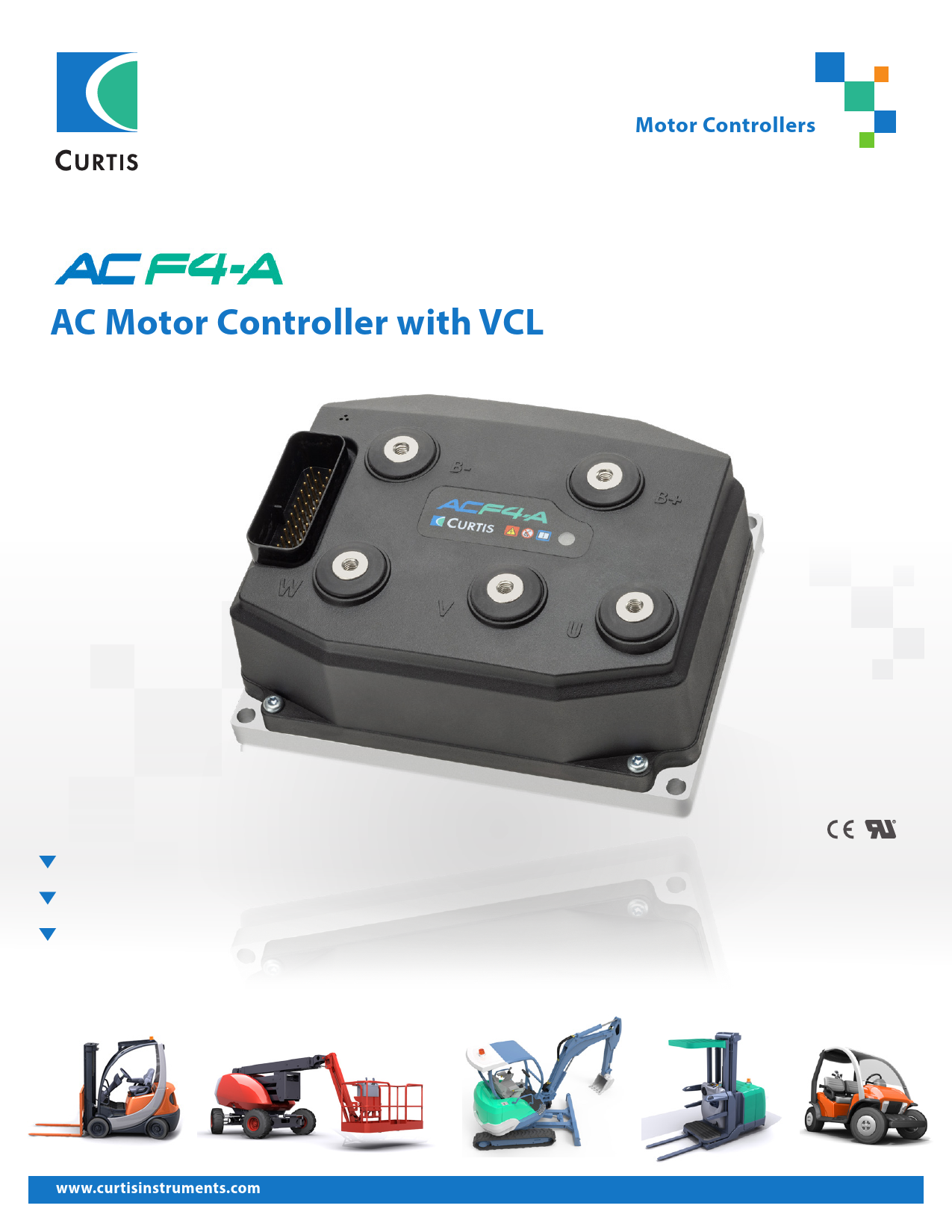
The Curtis Model AC F4-A Motor Controller is a high-performance and cost-effective solution for controlling 3-phase AC induction and PMAC motors in various applications. It features advanced VCL programming, CANbus comm…
[PDF] AC Motor Controller with VCL - Curtis Instruments
Superb Performance and Value. The Curtis Model AC F4-A Motor Controller provides accurate speed and torque control of 3-phase AC induction and PMAC motors.
Full PDF Document

If the inline viewer fails, it will open the original document in compatibility mode automatically. You can also open the file directly.
Extracted Text
Motor Controllers
AC Motor Controller with VCL

www.curtisinstruments.com

1

Superb Performance and Value
The Curtis Model AC F4-A Motor Controller provides accurate speed and torque control of 3-phase AC induction and PMAC motors.
The AC F4-A uses dual, high-performance ARM Cortex microprocessors to ensure the highest possible levels of functional safety, while providing highly efficient motor control and flexible system control capabilities. It is intended to control the Electric Traction (Propel), Hydraulic Pump and On-Engine Generator (OEG) Hybrid systems on mobile equipment applications such as Materials Handling Trucks, Aerial Work Platforms and Construction Equipment. In addition to the highly advanced motor control, the Model AC F4-A is also a powerful Vehicle Manager /System Controller, with significant CANbus system master capabilities.

FEATURES Fit for Purpose

You Feel It When You Drive It-- Maximum Torque, Minimum Losses, Full control

 High-efficiency, field-oriented motor control algorithms for 3-phase AC motors.
 Advanced motor control for maintaining optimal performance at all operating conditions.
 Provides real-time motor torque and power estimates for vehicle level power optimization.
 Compact, rugged housing with very small `footprint' for its power rating.

 The latest implementation of Curtis' renowned fieldoriented control algorithms, and our advanced PWM switching technology, assures maximum motor output torque and highest possible system efficiency across the entire torque/speed spectrum.
 Smooth and predictable drive control that only Curtis can deliver.

 Heavy-duty M6 busbars for motor and battery connectors.

 Sealed, 35-pin AMPseal I/O connector.

 Impervious to most oils, solvents, degreasers and other chemicals often encountered by industrial vehicles.

 IP65 and IP67 environmental protection as per IEC 60529.

 Exceeds latest global conformance requirements for functional safety, electrical safety and EMC.

 CE marked as a programmable safety device.

 UL583 Pending.

Motors

 Easily configured to work with any AC induction or PMAC motor.
 Improved motor auto-characterization setup allows simple on-truck pairing with different Induction motor types.
 Comprehensive library of induction and PMAC motor types stored in controller memory.

www.curtisinstruments.com

2

FEATURES continued

Get More Out of Your Battery-- Regardless of the Technology
 High-efficiency means more of your battery's energy is converted to motor output power.
 Fully configurable over- and under-voltage protection parameters.
 Wide operating voltage range allows use with the latest cell chemistries such as lithium ion.
 Configurable CANbus and VCL allows easy integration with the BMS (Battery Management Systems) typically found on lithium battery packs.
Powerful, High Performance Dual Microprocessors
 Dual-micro architecture achieves up to PL=D, category 2 functional safety under EN ISO 13849-1 / EN1175-1:1998+A1:2010.
 Ultra-fast processor speeds allow highly accurate control and regulation of voltage, frequency and current.
 Hardware `ready' for the forthcoming prEN1175:2019.
Customize Your Vehicle with VCL
 The Curtis VCL (Vehicle Control Language) allows Curtis AC motor controllers to perform as `vehicle managers', eliminating the need for costly, additional system controllers.
Inertial Measurement Unit (IMU)
 Six-Axis IMU for measurement of orientation, movement and impact detection (optional).

Highly Flexible I/O
 All I/O pins are multi-function, and can be configured to provide up to: � 27 digital inputs � 9 analog inputs � 2 potentiometer sources � 7 output drivers
Comprehensive CAN Master Capabilities
 Configurable 11 or 29 bit protocol support for CANopen or J1939 use.
 Dual independent CAN ports, available with full galvanic isolation (optional).
 `Plug and Play' support for Curtis CAN displays and a variety of CAN tiller heads from leading manufacturers FREI and REMA.
 Fully compliant with CANopen protocol DS301 profile.  Capable of acting as `CAN interpreter' allowing 3rd
party CAN devices with differing profiles to work on the same CAN network.
Improved Diagnostics
 Integrated, high visibility Status LED with simplified flash code sequence for at-a-glance system troubleshooting.
 Thermal cutback, warning, and automatic shutdown provide protection to motor and controller.
 Error logging and fault history tables with CAN Emergency Messages.

CAN-based Programming
 Model AC F4-A is programmable over the CANbus. This allows `vehicle level' communication with many of the CAN-based service tools used by the major industrial truck manufacturers worldwide.
 Allows use of the Curtis Integrated Toolkit of development tools.

www.curtisinstruments.com

3

SYSTEM ACCESSORIES

Curtis Model 3141
A cost-effective, CAN-based LCD vehicle status display in a rugged 52mm diameter housing is the ideal partner to model AC F4-A.
 Large, easy-to-read 16-segment format LCD.
 Battery Discharge Indicator, Service (Hours) Counter and Diagnostic/ Message Center functions.
 Sealed to IP65 (IP67 optional).
 12�48V nominal operating voltage range.
 CE compliant, UL583 recognized component.
 Optional backlight and heater.

The Curtis Integrated Toolkit
A fully integrated suite of development and diagnostic tools for use on CAN systems using Curtis and other 3rd party CAN-based products. It is comprised of the following tools that run in a shared environment:

 Launchpad Starting point and project editor.
 Programmer Used to configure parameter, view monitor values, and view active faults and the fault history.
 TACT Improved version of the stand-alone oscilloscope/ datalogging tool.

 VCL Studio Editor and compiler for VCL software.
 Menu Editor Tool to create and modify programming menus.
 Package & Flash Downloader tool to load you software into the CAN device.

The Curtis Integrated Toolkit is compatible with many leading USB>CAN interface dongles from Peak, Kvaser, iFAC, Sontheim, etc. Contact your local Curtis Sales office for further information.

MODEL CHART

Model

Nominal Battery Maximum Current: Maximum Current:

Voltage:

[S2-2 min]

[S2-60]

IMU

Isolated CAN

AC F4-A 24-375-001

24V

375Arms

185Arms

No

No

AC F4-A 24-375-101

24V

375Arms

185Arms

Yes

Yes

AC F4-A 36-500-001

24�36V

500Arms*

175Arms*

No

No

AC F4-A 36-500-101

24�36V

500Arms*

175Arms*

Yes

Yes

AC F4-A 48-375-001

36�48V

375Arms

175Arms

No

No

AC F4-A 48-375-101

36�48V

375Arms

175Arms

Yes

Yes

AC F4-A 48-450-001

36�48V

450Arms*

175Arms*

No

No

AC F4-A 48-450-101

36�48V

450Arms*

175Arms*

Yes

Yes

AC F4-A 80-250-001

48�80V

250Arms*

145Arms*

No

Yes

AC F4-A 80-250-101

48�80V

250Arms*

145Arms*

Yes

*Subject to change, please contact your Curtis sales representative for more information.

www.curtisinstruments.com

Yes 4

DIMENSIONS 5X M6X 1.0 - 6H 18 MIN

4X � 7.0 74.0

169.0 180.0

www.curtisinstruments.com

STATUS LED
129.0 140.0 5.5 5.5
75.0 12.0
5

CONNECTOR WIRING

Interlock

9 Input 5

KSI 1

Emergency Reverse

NO

NC

24 Input 9 14 Input 13 / Enc 2B

Coil Supply 13 Driver 1 / Input 21 2

Forward

22 Input 7

Driver 2 / Input 22 5

Reverse

33 Input 8

Driver 3 / Input 23 4

Lift

10 Input 10 (PWM)

Driver 4 / Input 24 3

Lower

11 Input 11 / Enc 1C

Driver 5 / Input 25 6

Optional Peripherals

Travel Limit User Input

12 Input 12 / Enc 2A 27 Input 19 / Pot 19 Supply

Driver 6 / Input 26 19 Driver 7 / Input 27 20

Traction Motor Throttle Input Brake Throttle Input External Power Supply

15 Input 6 / Pot 6 Supply 16 Input 1 / Pot 1 Wiper 7 GND 17 Input 18 / Pot 18 Wiper
7 GND 25 Input 14 / +12V Ext Supply 26 Input 31 / +5V Ext Supply

Driver 8 30
Input 31 / +5V 26 Input 3 / Enc 1A 31 Input 4 / Enc 1B 32
GND 18
U V

W

MODELS W/O ISOLATED CAN 23 CAN1 H

CAN PORT #1

35 CAN1 L

twisted pair, recommended

21

Short for Termination

34 120 CAN1

CAN PORT #2*

28 CAN2 H 29 CAN2 L

twisted pair, recommended

Input 2 / Motor Temp 8 GND 18
B+

Proportional Valve EM Brake
Load-Hold Valve Ext. Load 1 Main Coil Ext. Load 2 Ext. Load 3

Safety Disabled and
Reverse Polarity Protected Loads

Analog Output
Key-Switch
5V A/Sin Speed/ B/Cos Position GND Sensor

AC Induction
Motor
+�
Motor Temp Sensor

Fuse E Stop Pole B

Main Contactor Fuse

E Stop
Pole A

EMERGENCY STOP

23 CAN1 H

CAN PORT #1

35 CAN1 L

twisted pair, recommended

28 CAN2 H

CAN PORT #2

29 CAN2 L

ISOLATED CAN PORTS

34 Isolated GND

Not Used 21

B�

ISOLATED CAN MODELS

+
Battery
-

PINOUT CHART

ISOLATED GROUND

NOT USED ON

MODELS w/ Isolated CAN MODELS w/ Isolated CAN

CAN 1 TERM L CAN1 H CAN1 L

INPUT 4 ENC 1B CAN 1 TERM H
INPUT 8

DRIVER 8 DRIVER 6 INPUT 26 INPUT 3 ENC 1A

CAN2 H

INPUT 31 +5V SUPPLY

INPUT 9

INPUT 18 POT 18 WIPER

INPUT 6 POT 6 SUPPLY

COIL SUPPLY

CAN2 L

INPUT 19 POT 19 SUPPLY

INPUT 14 +12V SUPPLY

35

34

33

32

31

30

29

28

27

26

25

24

23

22

21

20

19

18

17

16

15

14

13

12

11

10

9

8

7

6

5

4

3

2

1

INPUT 12

INPUT 10

INPUT 2

DRIVER 5

DRIVER 3

DRIVER 1

ENC 2A

(PWM)

MOTOR TEMP

INPUT 25

INPUT 23

INPUT 21

INPUT 11 ENC 1C

INPUT 5

GND

DRIVER 2

DRIVER 4

INPUT 22

INPUT 24

KSI

INPUT 7

DRIVER 7 INPUT 27

GND

INPUT 1

INPUT 13

POT 1 WIPER

ENC 2B

www.curtisinstruments.com

6

SPECIFICATIONS
Nominal Input Voltage Minimum Voltage Brownout Voltage Maximum Voltage PWM Frequency
Maximum Controller Output Frequency Electrical Isolation to Heatsink Storage Ambient Temperature
Operating Ambient Temperature
Thermal Cutback
Design Life Package Environmental Rating
Weight Dimensions W x L x H
EMC Safety
UL

24V

36�48V

48�80V

12V

18V

24V

8V

12V

16V

33V

63V

100V

10 kHz nominal (adjustable)

800Hz

500Vac

�40�C to 95�C

�40�C to 50�C

Controller linearly reduces maximum current limit with an internal heatsink temperature from 85�C (185�F) to 95�C (203�F); complete cutoff occurs above 95�C (203�F) and below �40�C (�40�F).

20,000 hours

IP65 and IP67

1.9Kg (4.4lbs)

180mm x 140mm x 75mm

Designed to the requirements of EN 12895:2015

Designed to the requirements of EN ISO 13849-1:2015

UL583 Pending

WARRANTY Two year limited warranty from time of delivery.

is a trademark of Curtis Instruments, Inc.
www.curtisinstruments.com

Specifications subject to change without notice

�2021 Curtis Instruments, Inc.

50354 REV D 8/21
7