For a copy hereof, please contact LINAK. FOR MOUNTING INSTRUCTIONS AND GUIDANCE IN USAGE, PLEASE SEE THE RELEVANT USER MANUAL.
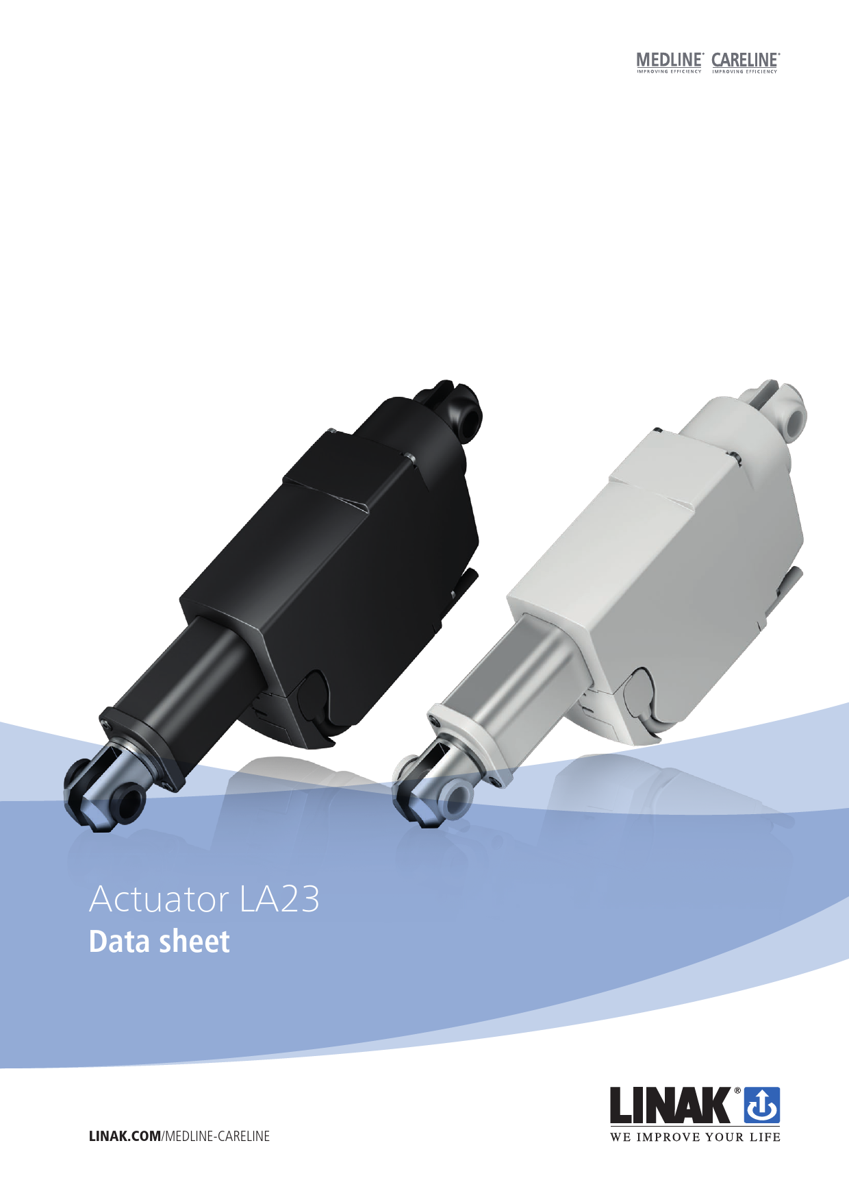
Actuator LA23
Data sheet
LINAK.COM/MEDLINE-CARELINE

LA23
The LA23 actuator is a small and strong push/pull actuator (up to 2,500 N). The LA23 can be used in various applications where size is important. Some of the benefits the LA23 offers you are: · Compact design · High lifting force · Exchangeable cables

Features and options: · Load in push: 2,500 N, 1,800 N, 1,500 N, 1,200 N, 900 N
or 300 N · Load in pull: 2,500 N, 1,800 N, 1,500 N, 1,200 N, 900 N
or 300 N · Housing colour: Black (RAL 9005), outer tube steel or black
Light grey (RAL 7035), outer tube steel · Protection class: IPX4, IPX6 · Motor: 12 V DC, 24 V DC · Stroke length: 20 - 500 mm (for stroke 300-500 mm max.
load is 1,000 N for pitch 3, 5, 6 and 9) Pitch 12 mm (for stroke 300-500 mm max. load is 900 N) Pitch 20 mm (for stroke 300-500 mm max. load is 300 N) · Built-in dimensions: 110 - 146 mm + stroke length · Positioning options: Potential free end stop signals
Hall potentiometer or Hall PWM position Single Hall, Dual Hall · Back fixture material: Plastic or steel · Nut: Guided · Safety nut: In push or pull (2,500 N and 1,800 N version only safety nut in push) · Mechanical spline: Yes

· Built-in electrical end-stop: Yes · Exchangeable cable: Yes · Static safety factor: 2.5 · Noise level: Max. 58.5 dB(A) (At nominal voltage and with
no load, according to EN ISO 3743-1) · Mechanical end stop: Yes · Integrated Control: Yes
Usage: · Duty cycle: 10%, 2 minutes continuous use followed by
18 minutes not in use · Usage temperature: +5° - +40° normal operating temp.
-30° - +50° according to test conditions: ISO 7176-9 · Storage temperature: -45°C to +70°C (according to ISO 7176-9) · Compatibility: Compatible with LINAK control boxes.
Please contact LINAK. · Approvals: IEC60601-1, ANSI/AAMI ES60601-1,
CAN/CSA 22.2 No 60601-01. LA23IC is not approved according to the above. LA23 in combination with CBD4, CBD5 & CBD6 has no approvals. · Flammability rating: Enclosure UL94-V0

LINAK.COM/MEDLINE-CARELINE

LA23 Ordering example:
23 6 1 A 0 1 0 00 250 A 4
IP degree:

4 = IPX4 6 = IPX6

Motortype:

A = 12 V B = 24 V (Running mainly with battery (CBJ1, CBJ2, CBJH, CBJC, wheelchairs)) G = 24 V (For OpenBus (CB20, CB16, CB6s)) not available with LA23IC

Stroke:

XXX = mm

Min. 020 mm, Max. 300 mm in steps of 5 mm

Recommended versions:

020 mm , 050 mm , 100 mm, 150 mm, 200 mm, 250 mm, 300 mm

Positioning:

00 = No positioning 01 = Potential free end stop signals 02 = Dual Hall digital positioning 03 = Dual Hall PNP positioning
1x = Hall potentiometer feedback 2x = Hall potentiometer feedback and potential free endstop 3x = Hall PWM position feedback 4x = Hall PWM position and potential free endstop 50 = IC with standard electrical endstop - no positioning 52 = IC with Standard Single Hall Positioning 6x = IC with Hall potentiometer feedback. 7x = IC with Hall PWM position feedback Xx for more information please call LINAK

Safety option:

0 = No safety options 1 = Safety nut for push 2 = Safety nut for pull 3 = Mechanical spline without safety nut 4 = Mechanical spline with safety nut

(pitch 3, 5, 6, 9, 12 or 20) (pitch 3, 5, 6, 9 or 12) (pitch 6, 9 or 12) (pitch 3, 5, 6, 9 or 12) (pitch 3, 5, 6, 9 or 12))

Housing colour:

1 = Black (RAL 9005) 2 = Light grey (RAL 7035) 3 = Black (RAL 9005) + black outer tube

Piston rod eye:

0 = Standard (steel) with slot (6.1 mm), eye Ø10.2 mm, incl. plastic bushings 1 = Standard (steel) with slot (6.1 mm), eye Ø10.2 mm (0231033) 2 = Standard (steel) with slot (6.1 mm), eye Ø12.3 mm (0231016)

Back fixture rotation:

0 = 0° clockwise A = 7.5° clockwise B = 15° clockwise C = 22.5° clockwise D = 30° clockwise E = 37.5° clockwise F = 45° clockwise G = 52.5° clockwise

H = 60° clockwise J = 67.5° clockwise K = 75° clockwise L = 82.5° clockwise 1 = 90° clockwise M = 97.5° clockwise N = 105° clockwise P = 112.5° clockwise

Q = 120° clockwise R = 127.5° clockwise S = 135° clockwise T = 142.5° clockwise U = 150° clockwise V = 157.5° clockwise W = 165° clockwise Z = 172.5° clockwise

Back fixture:

1 = Plastic with slot (6.1 mm), eye Ø10.2 mm (only for Standard push load) (0231017) (only for pitch 6, 9 or 12 and safety option 0 or 1 (push))
2 = Steel with slot (6.1 mm), eye Ø10.2 mm, incl. plastic bushings 3 = Steel with slot (6.1 mm), eye Ø10.2 mm (0231034) 4 = Steel with slot (6.1 mm), eye Ø12.3 mm (0231020)

Spindle type:

2 = 20 mm pitch (300 N) for stroke 200-500 mm max. load = 300N 3 = 3 mm pitch (2,500 N) for stroke 300-500 mm max. load = 1,000 N 5 = 5 mm pitch (1,800 N) for stroke 300-500 mm max. load = 1,000 N 6 = 6 mm pitch (1,500 N) for stroke 300-500 mm max. load = 1,000 N 9 = 9 mm pitch (1,200 N) for stroke 300-500 mm max. load = 1,000 N 0 = 12 mm pitch (900 N) for stroke 300-500 mm max. load = 900 N

Actuator type: 23 = LA23

Dimensions:

Back fixture orientation Option 1
Back fixture orientation Option 0

Drawing number: 0234024

The built-in dimension depends upon the chosen safety option and stroke length. Please see the table below to decide upon the built-in dimension.

Safety option
0 = No safety option 0 = No safety option 1 = Safety nut for push 1 = Safety nut for push 2 = Safety nut for pull 3 = Mechanical Spline for push 3 = Mechanical Spline for push 4 = Mechanical Spline & safety nut for push 4 = Mechanical Spline & safety nut for push
0 = No safety option 0 = No safety option 1 = Safety nut for push 1 = Safety nut for push 2 = Safety nut for pull 3 = Mechanical Spline for push 3 = Mechanical Spline for push 4 = Mechanical Spline & safety nut for push 4 = Mechanical Spline & safety nut for push
0 = No safety option 0 = No safety option 1 = Safety nut for push 1 = Safety nut for push 2 = Safety nut for pull 3 = Mechanical Spline for push 3 = Mechanical Spline for push 4 = Mechanical Spline & safety nut for push 4 = Mechanical Spline & safety nut for push

Stroke length
20 - 49 20 - 49 20 - 49 20 - 49 20 - 49 20 - 49 20 - 49 20 - 49 20 - 49
50 - 200 50 - 200 50 - 200 50 - 200 50 - 200 50 - 200 50 - 200 50 - 200 50 - 200
201 - 300 201 - 300 201 - 300 201 - 300 201 - 300 201 - 300 201 - 300 201 - 300 201 - 300

Spindle pitch
6, 9, 12 or 20 3, 5
6, 9 or 12 3, 5
6, 9 or 12 6, 9 or 12
3, 5 6, 9 or 12
3, 5
6, 9, 12 or 20 3, 5
6, 9 or 12 3, 5
6, 9 or 12 6, 9 or 12
3, 5 6, 9 or 12
3, 5
6, 9, 12 or 20 3, 5
6, 9 or 12 3, 5
6, 9 or 12 6, 9 or 12
3, 5 6, 9 or 12
3, 5

Min. built-in Dimensions
160 168 160 168 172 180 196 180 196
110 + stroke 118 + stroke 110 + stroke 118 + stroke 122 + stroke 130 + stroke 146 + stroke 130 + stroke 146 + stroke
130 + stroke 138 + stroke 130 + stroke 138 + stroke 142 + stroke 150 + stroke 166 + stroke 150 + stroke 166 + stroke

It is possible to order LA23 with extended built-in dimensions if the following requirements are fulfilled

Spindle pitch = Spindle pitch =

6, 9, 12, 20

3, 5

Safety option 0 : No safety option

Safety option 1 : Safety nut push

Spindle pitch = 6, 9, 12 Safety option 2 : Safety nut pull

Spindle pitch = 6, 9, 12

Spindle pitch = 3, 5

Safety option 3 : Spline without safety nut

Safety option 4 : Spline + safety nut push

Max. built-in dimensions  730 - stroke  738 - stroke

 742 - stroke

 750 - stroke

 766 - stroke

Example: A) 6 mm pitch no safety option, stroke 200, BID can be max. (730 - 200) = 530 B) 3 mm pitch no safety option, stroke 20, BID can be max. (738 - 20) = 718

Technical specifications:

Power supply
12 V DC CBJ1/2, CBJH and CBJC OpenBusTM 12 V DC CBJ1/2, CBJH and CBJC OpenBusTM 12 V DC CBJ1/2, CBJH and CBJC OpenBusTM 12 V DC CBJ1/2, CBJH and CBJC OpenBusTM 12 V DC CBJ1/2, CBJH and CBJC OpenBusTM 12 V DC CBJ1/2, CBJH and CBJC OpenBusTM

Spindle pitch (mm) 3 3 3 5 5 5 6 6 6 9 9 9 12 12 12 20 20 20

Load max. Push or Pull
(N) 2,500 / 2,500 2,500 / 2,500 2,500 / 2,500 1,800 / 1,800 1,800 / 1,800 1,800 / 1,800 1,500 / 1,500 1,500 / 1,500 1,500 / 1,500 1,200 / 1,200 1,200 / 1,200 1,200 / 1,200
900 / 900 900 / 900 900 / 900 300 / 300 300 / 300 300 / 300

Motor type
A: 12 V B: 24 V G: 24 V A: 12 V B: 24 V G: 24 V A: 12 V B: 24 V G: 24 V A: 12 V B: 24 V G: 24 V A: 12 V B: 24 V G: 24 V A: 12 V B: 24 V G: 24 V

*Typical speed at 0/full load (mm / sec.) 3.1 / 2.5 3.2 / 2.6 3.3 / 2.7 5.4 / 4.2 5.4 / 4.5 5.6 / 4.6 6.6 / 5.2 6.4 / 5.5 6.7 / 5.5 9.9 / 7.5 9.5 / 8.1 9.9 / 8.1 13 / 9.6 12.6 / 10.4 13.3 / 10.7 21.5 / 18.6 21.6 / 20.2 21.8 / 20.6

*Typical current at 0/ full load (Amp.) 0.8 / 3.6 0.4 / 1.9 0.3 / 1.4 0.8 / 3.9 0.4 / 1.9 0.3 / 1.4 0.8 / 3.6 0.4 / 1.7 0.3 / 1.3 0.9 / 4.0 0.4 / 1.9 0.3 / 1.3 0.9 / 3.8 0.4 / 1.9 0.3 / 1.4 0.8 / 4.3 0.4 / 2.3 0.3 / 1.6

* Typical values, measurements are made with an actuator in connection with a stable power supply. The typical values can have a variation of ± 20 % on the current values and ± 10 % on the speed values.

Inrush current (Amp)
13.4 8.7 6.2 13.4 8.7 6.2 13.4 8.7 6.2 13.4 8.7 6.2 13.4 8.7 6.2 -

Safety nut and steel back fixture overview

Pitch (mm)
20 12 9 6 5 3

Load (N)
300 900 1,200 1,500 1,800 2,500

Safety nut

Steel back fixture Plastic back fixture

Not an option Optional in push or pull Optional in push or pull Optional in push or pull Optional in push (Safety nut 2,500 N not available in pull) Optional in push (Safety nut 2,500 N not available in pull)

Required in pull Required in pull Required in pull Required in pull Always required Always required

Only in push Only in push Only in push Only in push Not available Not available

Self-locking specifications
Spindle pitch 20 mm pitch 12 mm pitch 9 mm pitch 6 mm pitch 5 mm pitch 3 mm pitch

Without short circuit 100 750 750 1,200 1,600 2,500

With short circuit 300 900 1,200 1,500 1,800 2,500

Copyright © LINAK 2020.07 . MA M9-02-358-AD Chapter 5.15

Terms of use The user is responsible for determining the suitability of LINAK products for specific application. LINAK takes great care in providing accurate and up-to-date information on its products. However, due to continuous development in order to improve its products, LINAK products are subject to frequent modifications and changes without prior notice. Therefore, LINAK cannot guarantee the correct and actual status of said information on its products. While LINAK uses its best efforts to fulfil orders, LINAK cannot, for the same reasons as mentioned above, guarantee the availability of any particular product. Therefore, LINAK reserves the right to discontinue the sale of any product displayed on its website or listed in its catalogues or other written material drawn up by LINAK. All sales are subject to the Standard Terms of Sale and Delivery for LINAK. For a copy hereof, please contact LINAK.
FOR MOUNTING INSTRUCTIONS AND GUIDANCE IN USAGE, PLEASE SEE THE RELEVANT USER MANUAL
Adobe PDF Library 15.0 Adobe InDesign 14.0 (Windows)