File info: application/pdf · 126 pages · 67.82MB
Document preview and download links are below.
Extracted Text
FOR ENGINEERS AND ENGINEERING MANAGERS
OCT. 11, 1976
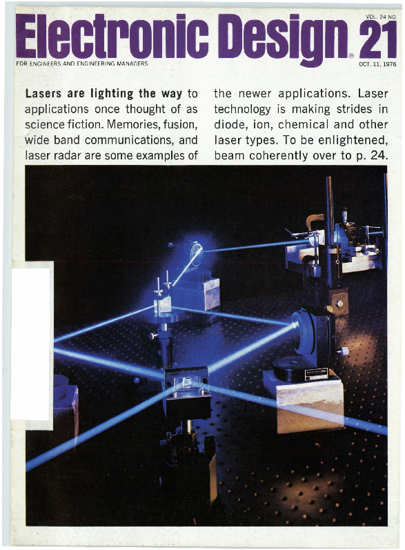
Lasers are lighting the way to applications once thought of as science fiction. Memories, fusion, wide band communications, and laser radar are some examples of
the newer applications. Laser technology is making strides in diode, ion, chemical and other laser types. To be enlightened, beam coherently over to p. 24.
New Sangamo Type 101 Aluminum Electrolytic Capacitors for up to 100 kHz filtering in Switching Power Supplies:
COOLER PERFORMANCE.
Type 101 Capacitors Electrical/Mechanical Specifications
Capacitance Range 450 uF to 465,000 uF
ESR Values at 20 kHz .0048 ohms to .040 ohms
Max. Ripple Current 40 amps at 65�C;
Capability at 20 kHz 31.4 amps at 85�C
Operating
-55�C to +85�C
Temperature Range
When you need longer-life capacitors for your higher-frequency (10 to
100 kHz) switching regulator power supply-play it cool.
Voltages Available Nominal Case Sizes
Terminal Connections
5 to 100 VDC
1.375" x 1.625" (34.93 mm x 41.28 mm) to 3.000" x 5.625" (76.2 mm x 142.88 mm)
Standard t~readed insert type
Look into new, cooler-operating Sangamo
External Insulation
Uniform polypropylene coating
Type 101 Computer-Grade
in a great new case. Specify Sangamo
Aluminum Electrolytic Capacitors.
Type 101 Computer-Grade Capacitors.
Their unique Thermal PackTM case
Write for complete specs and en-
mechanically secures the internal wound
gineering samples.
section. And compresses the extended conducting
Sangamo Capacitor Division, Box 128,
cathode foil into metal-to-metal contact with the Pickens, SC 29671; phone: (803) 878-6311;
aluminum case bottom.
TWX: 810-397-2496; Telex: 57-0441.
Results: Rugged construction. No need
for potting compound. Less weight. More volume for gas expansion. And vastly improved heat
SANGAMO
CAPACITORS transfer and dissipation, for cooler performance. Get high capacitance, low impedance,
high ripple current capability-and economy-
A DIVISION OF SANGAMO WESTON, INC.
CIRCLE NUMBER 2
ELECTRONlC DESIGN 21 , October 1 1, 1976
T0-5 RELAY UPDATE:
Solve your energy
crisis with TO-Srelays
O Low Coil Power Consumption
850
~ ~
...~ ~4~~~~~~~-~~--
i
0
210
432
SERIES
Power Dissipation at Nominal Coil Voltage
Subminiaturization and pc board compatibility two obvious advantages of Teledyne T0-5 relays. But there's another outstanding advantage: low coil power consumption. This feature is best illustrated in the above graph which shows our T0-5 relay power savings compared to other miniature relays. The Teledyne 412 Series dissipates about 30% less power than the .150" grid relay, and 50% less than the V2 crystal can. Our sensitive 432 Series is 65% less than the .150" grid. And 75% less than the V2 crystal can .
This means you can save over 6 watts in a typical system using, let's say, ten T0-5 relays. In the end, you gain significant advantages in terms of thermal and power supply considerations that can help prevent an "energy crisis" in your system.
Our complete line of T0-5 relays includes military and commercial/industrial types, with virtually all military versions qualified to established reliability MIL specs. For complete data, contact Teledyne Relays - the people who pioneered the T0-5 relay.
� Hybrid " T" Series SPOT & OPOT types with internal transistor driver and suppression diode
� "D" and "DD" Serles Mi litary and commercial/industrial versions with internal suppression and steering diodes
� Maglatch Series SPOT, OPOT, and 4PST magnetic latching types
� Centlgrid� Series World's smallest relay- only .225" (5 .72mm) high x .37011 (9.40mm) square
� Hi-Rel Series Screened versions for space flight applir.ations (NASA qualified)
� High Environment Series HI-temperature, Hi-shock, and Hi-vibration types
.._~TELEDYNE RELAYS
3155 West El Segundo Boulevard, Hawthorne, California 90250 Telephone (213) 973-4545
CIRCLE NUMBER 3
2
ELECTRONIC D ESIGN 21, October 11 , 1976
NEWS
19 News Scope
24 Lasers are being used in a host of new applications, including communications systems, nuclear fusion, video discs, supermarket scanners and pollution monitors. An Electronic Design special report.
35 Washington Report
TECHNOLOGY
41 MICROPROCESSOR DESIGN
52 Consider solid-state photodetectors for your next sensing application. But check these pointers on how they work and how best to apply them.
62 Control an LP-filter's cutoff frequency electronically. Cover a 20:1 range with a digital control that can be linearized and set with a thumbwheel switch.
68 Avoid failure of PC board components by limiting the circuit board's vibration under stress. Make the board stiffer, if necessary, to cut down movement.
72 Orion Hoch of AMS speaks on making your engineers responsible.
78 Ideas for Design: Control logic for �P enables single-cycle operation. Get precise voltage division without precision parts. Precision voltage-to-frequency converter uses only single supply voltage.
84 International Technology
PRODUCTS
87 Instrumentation: Wideband rf amplifier offers best gain flatness.
90 Packaging & Materials
102 Data Processing
94 Power Sources
108 Integrated Circuits
93 Modules & Subassemblies
111 Components
DEPARTMENTS
49 Editorial: Teaching the horse not to eat
7 Across the Desk
118 Advertisers' Index
112 New Literature
120 Product Index
114 Bulletin Board
120 Information Retrieval Card
114 Vendo~ Report
Cover: Photo by Bob Bachus, courtesy of Aerospace Corp., El Segundo , CA.
ELECTRONIC DESIGN is published biweekly by Hayden Publishing Company, Inc., 50 Essex St. Rochelle Park, NJ
07662 . James S. Mulholland Jr.. President. Printed at Brown Printing Co., Waseca , MN . Controlled circulation
postage paid at Waseca, MN and New York, NY, postage pending Rochelle Park, NJ. Copyright � 1976. Hayden
Publishing Company, Inc. All right reserved. POSTMASTER: Please send form 3579 to ELECTRONIC DESIGN, P.O. Box 13803, Philadelphia, PA 19101.
ELECTRONIC D ESIGN 21 , October 11 , 1976
3
Top performance in a tiny space. AMPMODU posts, receptacles and headers make your packaging designs as tight as necessary.
We've also made it easier to place pins on a board. Forget about positioning pins one at a time. Forget costly front-end insertion equipment. Because AMP engineering ability shows up in our recently introduced AMPMODU pin headers.
Pins are fully protected. Headers are polarized and have self-retention locking latches. Headers fit everywhere on a board, including board center.
Ten basic header styles offer several thousand possible variations. You can approach mass termination with AMPMODU headers. Up to 80 positions.
These headers now complement the AMPMODU interconnection system, which features dual cantilever spring beams in the receptacle, five basic contact types and board to board or board to wire versatility. The forgiving nature of the receptacle design also ensures a uniform, positive electrical contact with the mating posts, everytime.
At AMP our application, service and sales engineers are located throughout the world, and are ready to help you with prototyping as well as providing .a complete after-sale service.
For more facts about AMPMODU headers, write or call Customer Service. (717) 564-0 I00. AMP Incorporated, Harrisburg, PA 17105.
SEE US AT MILAN BIAS SHOW
~IVIP INCORPORATED CIRCLE NUMBER 4
AMP an d AMPMODU a re trademarks o f A MP Incorpo ra ted
Sr. Vice President, Publisher
Peter Coley
Editors
Editorial Offices 50 Essex St. Rochelle Park, NJ 07662 (201) 843-0550
TWX: 710-990 -5071 Cable: Haydenpubs Rochellepark
Editor-in-Chief George Rostky
Managing Editors: Ralph Dobriner Michael Elphick
Senior Associate Editor Stanley Runyon
Associate Editors: Sid Adlerstein Dave Bursky Samuel Derman Jules H. Gilder Morris Grossman John F. Mason Michael Shunfenthal
Contributing Editors:
Reduce Your Power Supply Size Peter N. Budzilovich, John Kessler Al berto Socolovsky, Nathan Sussman
Editorial Field Offices
and Weight By 70%
A new way has been found to substantially reduce power supply size and weight. Consider the large power supply shown at left in the above photo - it uses an input transformer, into a bridge rectifier, to convert 60 Hz to 5 volts DC at 5 amperes. This unit measures 6W'x4"x7W' and weighs 13 pounds. Abbott's new model Z5Tl0, shown at right, provides the same performance with 70%less weight and volume. It measures only 2Wx4"x6" and weighs just 3 pounds.
This size reduction in the Model Z5Tl0 is primarily accomplished by eliminating the large input transformer and instead using high voltage, high efficiency, DC to DC conversion circuits. Abbott engineers have been able to control the output ripple to less than 0.02% RMS or 50 millivolts peak-to-peak
maximum. This design approach also allows the unit to operate from 100 to 132 Volts RMS and 47 to 440 H ertz. Close regulation of 0.15%and a typical temperature coefficient of 0.01% per degree Celsius are some of its many outstanding features. This new Model "Z" series is available in output voltages of 2.7 to 31 VDC in 12 days from receipt of order.
Abbott also manufacturers 3,000 other models of power supplies with output voltages from 5 to 740 VDC and with output currents from 2 milliamps to 20 amps. They are all listed with prices in the new Abbott catalog with various inputs:
60~to DC
400~to DC
28 VDC to DC 28 VDC to 400 ~
12-28 VDC to 60 ~
East J im McDermott, Eastern Editor P.O. Box 272 Easthampton, MA 01027 (413) 527-3632
West David N. Kaye, Senior Western Editor 8939 S. Sepulveda Blvd. , Suite 510 Los Angeles , CA 90045 (213) 641 -6544 TWX: 1-910-328-7240 Jim Gold , Western Editor 1537 Shasta Ave. San Jose, CA 95128 (408) 279-8588
Editorial Production
Marjorie A. Duffy, Production Editor James Keane, Copy Editor
Art
Art Director, William Kelly Richard Luce, Anthony J. Fischetto
Production
Manager, Dollie S. Viebig Helen De Polo, Anne Molfetas
Circulation
Please see pages 1836-1848 of your 1976-77 EEM (ELECTRONIC ENGINEERS MASTER Catalog) or pages 676-682 Volume 2 of your 1976-77 GOLD BOOK for Information on Abbott Modules.
Send for our new 60 page FREE catalog.
Director, Barbara Freundlich Trish Edelmann
Information Retrieval
Peggy Long
5�51���1�� I t r a n s i s t 0 r
GENERAL OFFICES
w. 5200 Jefferson Blvd.
Los Angeles, CA 90016
LA B 0 RAT 0 RI ES I NC 0 R PORAT ED (213) 936-8185
'
Telex 69-1398
CIRCLE NUMBER 5
6
EASTERN OFFICES 1224 Anderson Ave. Fort Lee, NJ 07024
(201) 224-6900 Telex 13-5332
Advertising Promotion
Susan G. Apolant
EL ECTRON IC D ESIGN 21 , October 11 , 1976
Across the Desk
Converter series includes several useful features
On p. 172 of the June 7 issue of ELECTRONIC DESIGN, you featured an 8-channel R/D converter. Since ELECTRONIC DESIGN has a reputation and policy of comparing competitive units, I was surprised you did not mention DDC's hybrid synchro or resolver converters in the story.
We at DDC have a similar product, the Model HMSDC series, that has been available for over three years. It is far superior to the MN7200 in that it features simultaneous sampling, 150 �s conversion time, single-line-per-channel addressing, a temperature range of
- 55 to + 105 C. It also can ac-
commodate multiple references with mixed frequencies and different line~to-line voltage levels.
For full data Circle No. 319 Steve Muth
Marketing Product Manag er ILC Data Device Corp. Airport International Plaza Bohemia, LI, NY 11716
ED issue may inspire youth to greater glories
Your "200 Years of Progress" issue of Feb. 16, 1976, merits sincere congratulations for a job well done. This year, when "Bicentennial" has too often become distorted to "Buycentennial," your issue provides a refreshing assurance that our past can be portrayed with the justifiable pride it deserves without displaying Old Glory on a beer can or bumper sticker.
I hope copies of this issue will find their way to reference shelves where future young scientists may receive inspiration to say "But, folks, you ain't seen nothin' yet!"
In the interests of accuracy, and without being too critical, I'd like
to call attention to the statement on page 121 that "Telstar settled int;o a nearly perfect orbit, in which the satellite appeared to hover over the same spot." Unfortunately, that is inaccurate, since a synchronous orbit of about 22,000 miles is implied. Telstar had an apogee of 3503 miles, a perigree of 593 miles, and a period of 157.8 minutes.
Syncom, by Hughes, in February, 1963 became the first to achieve sync.hronous orbit, but without operating. Syncom 2, in July, 1963, followed by Syncom 3 in August, 1964, both achieved synchronous orbits and operated. Many have followed since then to this most useful position in space
As one of a team of General Electric engineers working in 1960 to develop a synchronous satellite called Advent, I remember the arguments between recognized experts of orbital mechanics as to whether a stable, synchronou s orbit was possible or whether it was a theoretical "knife edge" condition that could neither be attained nor substained.
Name Withheld
Inaccuracies disputed in exchange on hybrid amp
In your June 7 issue (ED No. 12, p. 32) Fred Pouliot of Analog Devices generated inaccuracies of his own in attempting to correct the "inaccuracies" that appeared in the new product story "Hybrid Isolation Amplifiers Avoid Transformers but Maintain Isolation" (ED No. 2, Jan. 19, 1976, p. 91 ) .
He stated that the Model 275 requires a board area of 8.75 in.2 and has a volume of 7.79 in.3 � The combined figures for the BurrBrown 3650 isolation amplifier and
(continued on page 10 )
Electronic Design welcomes the opm1ons of its readers on the issues raised in the magazine's editorial columns. Address letters to Managing Editor, Electronic Design, 50 Essex St. Rochelle Park, N.J. 07662. Try to keep letters under 200 words. Letters must be signed. Names will be withheld on request.
ELECTRONIC DESIGN 21 , October 11. 1976
OPTRON
OPTICALLY COUPLED
ISOLATORS
NEW HIGH ISOLATION VOLTAGE "DIP" SERIES OFFERS HIGH TRANSFER RATIO
Now, OPTRON provides a 5 kV isolation voltage capability for its standard six pin plastic dual-in-line isolators. A new, unique internal design allows high voltage isolation while still maintaining a high current transfer ratio. The 5 kV DC or 3750 rms AC feature is available for all devices in OPTRON 's popular OPI 2100 and OPI 3100 series.
OPTRON's extended " DIP" series includes JEDEC types 4N25 through 4N38A, features complete interchangeability with popular industry types and provides an inexpensive coupler for every application. Devices are available with isolation voltages of 1500, 2500 or 5000 volts with minimum current transfer ratios rang-
ing from 2.0 to 500%. OPTRON's " DIP" and
a full line of other isolator packages with isolation voltages to 50 kV provide the versatility required for maximum electrical and mechanical design flexibility.
1.5 kV isolation with
..60% current transfer ratio.
Phototransistor base lead OPI 102 available. Hermetic T0-5
package .
OPI 110
10 kV isolation and 40% current transfer ratio. 4 �.Sec switching time in low cost miniature plastic package.
Detailed technical information on " DIP" and other isolators as well as all OPTRON optoelectronic products ... chips, discrete components, assemblies, and PC board arrays . . . is available from your nearest OPTRON sales representative or the factory direct.
OPTRON, INC.
1201 Tappan Circle Carrollton, Texas 75006, U.S.A. 214/242-6571 � TELEX-73-0701 TWX-910-860-5958
CIRCLE NUMBER 6
7
Draw one of these:
I � �'
I
I
Never thought you'd own a Porsche, did you? Well, there's only
one way to find out: fill out the
coupon. Advanced Micro Devices will
send you a contest kit that includes two samples of your choice of three terrific high-speed comparatorsthe Am685, Am686 or Am687 -
applications materials, data sheets and contest entry form.
Then you design an original application using the high-speed ~omparator you've chosen. That
shouldn't be too hard to do because tial experts will pick the top 10
Advanced Micro Devices' compar- designs. A drawing will be held to
ators are the fastest, most accurate � determine the winners. And we'll
parts you can get. Anywhere.
announce the names of the winners
If you're the winner, you'll own by March l, 1977.
a brand new, shiny, speedy Porsche In the meantime, you've got
924. Which is one of the fastest, some very important things to think
most accurate cars you can get. about. Like what color you want.
If your design comes in second or Do you want a silver body with
third you'll win a Porsche Chrono- black interior? Red with saddle?
meter. The next six winners win Blue with tan? How about a gold
Porsche Racing Team Jackets.
racing stripe along the side?
You must have your entries in
And you thought linear com-
by January 15th. A panel of impar- parators were boring.
Advanced Linear
~
Advanced Micro Devices� 901 Thompson Place , Sunnyvale , California 94086 �Telephone (408) 732-2400 � Distributed nationally by Hamilton/ Avnet, Cramer and Schweber Electronics.
8
ELECTRONIC D ESIGN 21, October 11 , 1976
Drive one of these:
First, the kit. Then, the car.
Don't wait around! Only the first 3,000 entries will be eligible. Send us the coupon, attached to your company's letterhead. No letterhead, no kit.
r---- -- - ---------------------------- ,
Advanced Micro Devices, 901 Thompson Place Sunnyvale, California 94086
I'm a player. Here's my coupon and letterhead. Send me the kit and the parts.
NAME COMPANY ADDRESS PART TYPE Am685 D Am686 D Am687 D (Check Box)
L- ---------------------------------- ~
EL ECTRO NIC D ESI G 2 1, Octobe r 11. 1976
9
Premier Electronic Cabinets and Cases
� ISTHETICS KEYED TO MODERN SYSTEMS � RUGGED-FUNCTIONAL CONSTRUCTION
� ECONOMICAL PRICING PROMPT SERVICE & AVAILABILITY
ACROSS THE DESK
(continued fr01n page 7)
the Model 700 isolated supply are 3.29 in.2 and 0.95 in.3, respectively.
In addition, he stated that "The Analog Devices Model 275 includes in its specifications, errors created by the power supply. The external supply required for the BurrBrown unit has additional error terms that must be considered."
Leakage current is one of the most important isolation specifications. The AD275 is specified at 8 �,A max (115-V ac, 60 Hz ) ; the Burr-Brown 3650 plus the Model 700 have a total of 1.5 �.A max at a higher voltage ( 240-V ac, 60 Hz ) .
Marketing people (me included ) tend to be biased towards their own products. But, in matters concerning one product vs. another it is the customer who ultimately decides which product best serves his needs. So, we'll see Fred, we'll see.
Dennis Haynes Product Manager Burr-Brown Research Corp. International Airport Industrial Park Tucson, AZ 85734
Misplaced Caption Dept.
TVA series vertical AssemblJConstruction Details (1 Frame, 2 End Panels, Rear Door)
-----�
----e
----G
1. Trim: extruded anodized aluminum with textured vinyl inlays
2. Outside removable flush end panels (16 ga.)
3. Recessed hand grip for panel removal
4. 2 pr. panel mounting angles, fully adjustable front to rear with tapped 10-32 holes on EIA & WE Standards spacing (12 ga.)
5. l" dia. holes for cable entry beneath base
6. Recessed caster mounting holes 7. 1 piece formed steel base pro-
vides for heavy equipment mounting area and concealed caster mounting (14 ga.) 8. 1 piece solid top for extra rigidity and squareness (14 ga.) 9. Foam gasketing (3 sides) 10. Magnetic closure gasket 11. Door stiffener channel 12. Keyed latch and brushed aluminum pull handle 13. Horizontal cross�brace and panel mounting angle supports 14. Quick release, spring loaded door hinges (top and bottom) 15. 11/e" dia. knock-outs for rear cable entry underneath rear door 16. Formed steel uprights (14 ga.) provide 1/2" recess to panel mounting angles � .
All features shown are standard in the Trimline TVA Series
Welded, formed steel construction
CIRCLE NUMBER 8
10
Let's see. We'll say it uses three microprocessors, consumes 800 milliwatts, delivers 45 watts rms, has a sensitivity of 2 microvolts, and never breaks down.
Sorry. That's Gerard Dou's "SelfPortrait," which hangs in the Rijksmuseum in Amsterdam.
ELECTRONIC DESIGN 21 , October 11, 1976
FOR RELIABLE OPENFRAME POWER SUPPLIES.
SOC, our new line of open-frame power supplies:
� Standard voltage and package sizes � 115/208/230 Vac input standard �Made in U.S.A. with quality components �No overshoot with turn-on, turn-off or power
failure
�Stocked for immediate delivery � Conservatively designed and rated � Low heat dissipation, high temperature stability �One-year warranty, worldwide service organization
�UL recognized
Output Current (Ade)*
Model No.
soc 2-3 soc 2-6 soc 2-10 soc 5-3 soc 5-6 soc 5-10 soc 12-1.6 soc 12-4.0 soc 12-6.0 soc 15-1 .5 soc 15-3.0 soc 15-5.0 soc 24-1 .0 soc 24-2.2 soc 24-3.5 soc 28-0.8 soc 28-2.0 soc 28-3.1
Serles
A B
c
A B
c
A B
c
A B
c
A B
c
A B
c
Voltage��
2V 2V 2V
5V 5V 5V
12V 12V 12V
15V 15V 15V
24V 24V 24V
28V 28V 28V
@ 4o�c
3.0 6.0 10.0
3.0 6.0 10.0
1.6 4.0 6 .0
1.5 3 .0 5.0
1.0 2.2 3.5
0 .8 2.0 3.1
@ so�c
2.4 4.9 8.0
2.4 4.9 8.0
1.3 3.0 5.0
1.2 2.6 4.2
.75 1.9 2.9
.64 1.7 2.6
@ eo� c
1.8 3.8 6.5
1.8 3.8 6.5
1.0 2.5 4.2
1.0 2.2 3.5
.55 1.6 2.4
.45 1.4 2.0
� Free-air rating - no external heatsink.
�� �5% adjustable.
Price
$32 54 67
32 54 67
32 54 67
32 54 67
32 54 67
32 54 67
Common Specifications: AC Input Power: Vac 105-125, 190-226, 210 to 250 available by using taps on transformer. Frequency 50 to 63Hz. (Derate 10% at 50Hz.)
Voltage Regulation (comb. line and load): � 0.15% + 6mV for 105 to 125 Vac and 100% load change. Voltage Ripple and Noise: 1.5mVrms, 5mVpp. Temperature Coefficient: 0.03%/�C. Drift (24 hours): 0.2% after 1-hour warm-up. Remote Sensing: 1OOmV maximum drop in each leg. Operating Temperature: 0�C to 60�C. Storage Temperature: - 20�C to +85�C. Overvoltage Protection: Available on all models except 2 volt. Specify by adding " VP" suffix to model number and add $8 to unit price . Current Foldback: Automatic, factory-set to
140% of rated (40�C) output current. Cooling: Convection. Finish: Black anodize.
Call us for OEM discounts:
(603) 668-4500. Sorensen 676 Island Pond Rd., Manchester, N.H. 03103.
(A Raytheon Company) CIRCLE NUMBER 9
How can you guarantee your product
for nineqt days if the parts that go into it
aren't guaranteed for ninety seconds?
-
'l!'"'""The llF. Guarantee When you're in the business of
market ing information systems
rrantslh,;molded<"'' 3 '
and modems that Sell from $500 to $50,000 .It CIOeSn't heIp to have YOUr CUStOmerS think Of YOU aS anythi.ng less than a rea lly solid
MFtlectromcswafromdefectsforonevear ~><imlldaattoerotofbpeufrrcehease . b defectivedun~gth"
troAnyosc1llatorfoundedt~o~hefa<tory. pa>tage p::~o.df~~,~,~pbaeirroertu. rantouropuon . rep\acement
operation .
~v1thout charg~ I mit 1\S hablhly to the repair
Of course, you're on ly as solid as
an~,~~1;'.,~;~;~~e~1oi1here1urnedMF
� plLIC�"" _ '" _ the products you sell.
oscill��O' ,..-onNICS CORP.
The _best way to get your custom-
eurcst biesl 1teov1mngak1en ytohuat apnrdodyuocutr bperottde-r than anyone else-and to guarantee it.
t!:-~.:":�':.&a'm.'l'il"l'a"l"i~''1"ii"11'-i4a"i"ia"iri��i11l" i111l.~ ,1l1i1i�i1l-1
1111 l ' " " ' ' '"" ''"
I._
~�
But how can you be sure nothing will go
wrong with the machines you make if you ca n' t be sure of th e parts you put into
them? The answer is you ca n't, unless you're
using guaranteed parts . At MF Electronics, we make molded
crysta l osci ll ators the best way anyone
After the crysta l and ot her pa rts are attached to the base, the cap is glued on, creating a bond that's tenuous at best.
A ir seeps through this bond, allowing di rt and moisture to collect. You've got a lea ky oscillator, one that's prone to loose
knows how to make them. Since we feel parts and electri cal shorting. That's how
they're the best, we're able to guarantee deadly a breath of fres h air can be to the
them for one fu ll year.
inside pf an oscill ator.
The difference between oscillators.
W h at sepa rates good oscill ators from bad is space. Space is one t h ing t h e r e sho ul dn ' t be any of in side an osc i l lator. Bu t th e way mos t oscill ator s are made, space is one thing you ca n count on.
The un-holey oscillator: It's molded. What a blessing.
va rious osc ill ators . H e found th at MF's molded oscillator lasted 3000 hours in an 85�C/85% relative humidity test. If you've ever done any oscillator testing yourself you know how remarkabl e that is.
Two more solid reasons to use MF Crystal Oscillators.
3rd overtone crystals are used in MF's molded osc illators to provide greater electrica l and mechanical stabil ity in frequencies exceed ing and includi ng 20 M Hz.
And an MF molded osci llator is the on ly one made that meets the U L oxygen index guideline of 28%.
Because we're solid, your prod uct is more solid.
So w hen you use MF mo lded crysta l oscill ators, you' re giving your prod uct a more efficient component, a heart th at w ill beat longer. And your customers w ill be givi ng you fewer complaints and service call s.
MF Electronics is the only compa ny that makes mo lded crys tal osc ill ators. We invented them.
We make w hat we think are th e best crystal oscill ators you can buy. And we guarantee them, so your prod uct can be "the best you ca n buy."
Guaranteed!
The hollow truth about crystal oscillators.
Look at this osci llator. The fact that we ca n lift the cap to show you w hat's wrong w ith it shows you w hat's wrong w ith it.
A molded oscill ator, on the other hand, has no holes, no open spaces, nothing to hide and nowhere to hide it. Its crystal is hermeticall y sealed and set in a monolithi c block of solid black plastic. There are no spaces for air to penetrate, no room for dirt or moisture to accumul ate. Wave soldering ca n't even deteri ora te th e unit, so there's no danger of loose pins or joints.
A test that rings true.
One of our customers, w ho is also one of the country's largest users of crysta l clock osci llators, tested the performance of
THE MF GUARANTEE
MF Ele ctronics warrants this molded crystal oscillator to be free from defects for one year from date of purchase.
Any oscillator found to be defective during this period may be returned to the factory, postage paid , for repair or, at our option , replacement without charge.
MF Electronics limits its liability to the repair and/or replacement of the returned MF oscillator.
.__.,ELEGTROl\llGS GORR 118 E. 25th St., New York, N.Y. 10010 (212) 674-5360 TWX: 710-581 -4 109 CIRCLE NUMBER 1 0
-. .TEST
CARRIER OH I RI DETECT
FRROR
-X\tlT DR;;~
11ATA
' $ For two-wire, full-duplex operation at 1200 BPS, Universal Data
UNIVERSAL Systems proudly announces the Model 12�12, the newest addition NEWEST to the UDS family of data modems. The unit operates synchroMODEM nously or asynchronously over unconditioned dial-up or private
telephone lines. Terminal interface discipline with the 12�12 is identical to that
commonly used for 103/113 modems. Using experience-proved phase shift modulation techniques, the UDS-12�12 transmits at 1200 BPS or any integral sub-multiple rate, without restrapping or adjustments.
The 12�12 is insensitive to word length, and it includes integral provision for automatic remote and local loopback testing. Delivery: 45 days ARO . For technical details contact UDS today.
$600 Single Unit Price.
Iii universal daba susbenrii 4900 Bradford Drive � Huntsvill e, Alabama 35805 � Telephone (2 05 ) 837 -8100 � T WX 810 -726 -2100
CIRCLE NUMBER 11
Today more than ever��� We make your
16-pin4K RAM business our business.
Our Austin plant has tripled volume production of the MCM6604.
Again.
and again last quarter!
~MOTOROLA
S e m iconduc 'fors
MOTOROLA SEM ICONDUCTOR PRODUCTS I NC. � P.O. BOX 2091 2 � PHOENI X, AZ 85036
-still
the production house
14
For hundreds, or for hundreds of thou-
sands to meet volu me product ion 4K RAM need s, ca ll
your aut horized Motorola d istrib utor or Moto rola sa les
offi ce.
ALABAMA, Hunln1lle . . . . . . . . . , �Hall�M1rk Elect1onlc1 .. . �
ALABAMA, Huntsville . . . ..... . , . , . H1m1lton / Avnet Electronu:
ARIZONA. Phoemx .
. ..... H1mllton/ Avnet Electronic
ARlZONA, Phoenix . . . . . . . . .. .. .Liberty Electronics/ Am:o
CALIFORNIA. Culver City
Hamilton Eleclro Sales/
. (205) 837-8700
. .(205) 533-1170
::t:8~J ~~~~~~~ (231) 558� 2000
CALIFORNIA, El Segundo .
. . Liberty Electronics Corp
. ' .(213) 322-8100
CALIFORNIA, ltv1ne .. . . , ....... , .Cramerf Los Angeles . .
.. (213) 771-8300
CALIFORNIA, Mounl11n View . , . Erm1r Electronics. Inc.
. '' . (41 5} 961�3611
CALIFORNIA, Mount11n View
. Ham1Uonf Avnel Elacll
CALIFORNIA, San Diego ..... . .. Hamlltont Avnet Electr
. . ''. (415) 961-7000 ..... (714)27g�2421
CALIFORNIA, San Diego . CALIFORNIA, Sunnyvale . .
' .. ' Lltle1ty Elec11on1csf S . .Cramerf San Franc1sc
. . '.' . (71 4) 565-9171 . . {408) 739-3011
COLORADO, Commerce C11y , ... Elm1r Elecironlcs, In
. ' ' . .. (303) 287-9611
COLORADO, Denver . . .
. .... HamUton / Av ne! E!e
. ' ' .. (303) 534-12 12
CONNECTICUT, Danbury . .
. . Schweber Eleclroni
' . . (203) 792-3500
CONNECTICUT, Geo rge1own . . . Hamllton/ Avnet Ele
.. (203) 762�0361
CONNECTICUT, Norlh Haven . . Cramer/ Connectlc
' .. ' (203) 23Q-564 I
FLORIDA, Ft Lauderdale
Hamilton/ Avnet El
... . . .. (305)Q25-5401
FLORIDA, Hollywood
Sch..,..eber Electro
'. (305) 927-0511
FLORIDA, Orlando .
. C11mer / Orlando
'' .. {305) 894-1511
FLORIDA, Orlando
Hall-Mark Eleclr
(305) 855- 4020
GEORGIA, Atlanta
Cramer / AUanla
(4041448-9050
GEORGIA. Norc ross ILLINOIS, Chicago .
Hamoltonl Avnet Newa1k Electr
,(404) 448-0800 (312) 638�4411
ILLINOIS, Elmhurst lndu1t1111 Park Sem1conducto
lnc . 1 Ch1cago
(312) 279-1000
ILLINOIS, Elk Giove V1ll1ge
Schweber El
1312)593-2740
ILLINOIS, Mt Prospect
C1amer1Ch1c
.(312) 593-8230
ILLINOIS, Sch1llar P11X .
HamUtonl Av
(312) 678-6310
IND IANA, lnd1anapolls
Graham Ele
(317) 634�8202
INDIANA, lnd1anapohs
Pioneer / In
.. (3171849-7300
KANSAS, Lenexa . KANSAS, Lenexa MARYLAND, G11thersburg
. ' . ' . H�ll�Mark .Ham.uon / Cramer
(913)888-4747 (9 13) 888-8900 (301) 948-0110
MARYLAND, Ga1the11burg
.Pioneer/
(301) 948-0710
MARYLAND, Hanover
Hammon
(301) 796-5000
MARYLAND, Rockville
Schweb
(301) 881-3300
MARYLAND, Savage
Pyttronl
(301) 792- 7000
MASSACHUSETTS, Le11ington . H11vey
' - (617) 861-9200
MASSACHUSETTS, New1on
Crime
(617) 969-7700
MASSACHUSETTS, Wallham
. Schw
.
(617) 890-8484
MASSACHUSETTS, Woburn ... . H1m1
....... . (617)933-8000
MICHIGAN, Detroit . MICHIGAN, Livonia
. .....AS E . Ham
..... (313) 491 -1 01 2
t �e 1ec�1;on1cs� �
. ... (313)522-4700
MICHIGAN, Livonia - . . . . .. Pio
It . . . .
'' .. (313) 525-1800
MINNESOTA, Eden Prairie .
. ..Sc
c1ronlc1 .
(612) 941�5280
MINNESOTA, Edina.
. .... Cr
aapolls . . . . .. . .... . . , (812)835-781 1
MINNESOTA, Edma
� H
net Electronics .
(61 2) 941-3801
MISSOURI, Hazelwood
H
net Electronics . . . . . . . (31 4)731-1 144
MISSOURI. Earth City
lectron1csf SI Louis
(3 14)291-5350
NEW JERSEY, Cedar Grove
vnat Etectronlcs .
(20 1) 239-0800
NEW JERSEY, Cherry Hiii
nnsylv1nla .. . .. .
(609) 424�5993
NEW JERSEY, Mt Laurel
Avnet Electronics
(609) 234�2133
NEW JERSEY, Moorestown .
ctro nlcs .... .. . . . '. '. (609) 235-1900
NEW JERSEY, Pennsauken .
ct11c Service Co..
� . (609) 662-4000
NEW JERSEY, Saddle Brook
lectronlcs ...
. (20 1) 797-5800
NEW JERSEY, Some11et ..
er Electronics ..
. (201) 469-6008
NEW MEXICO, Albuquerque .
n/ Avnet Electronics
(505) 7115-1500
NEW YORK, Farmlngd�I� NEW YORK, Haupp1uga. L.1.
NEW YORK. Rochester �
Elec tronlc�
e~~~~~~.':t'!~d.. ' . . ' .
. ' (518) 694-6800 . (518) 231-5600
(716)275-0300
NEW YORK, Rochester �
llon Avnet Elactronlcs
(718)4 42-7820
Nf.W YORK, Rochester
ebl'r Elwcuonics
(718)401�4000
NEW YORK, Syracuse
tr Syracuse
..
(315)437-11671
NEW YORK, East Syracuse
Uton/ Avnet Electronics
(315) 437-2642
NEW YORK, Westbury, LI. NEW YORK, Westbury, LI.
u . NEW YORK, Woodbury,
mllton / Avnet Electronics hwaber Eleclronlcs arvey Eleclronlcs .
'. (518)333-5800 (5 16)334 -7 474 (5111) 921-8700
NORTH CAROLINA. Greens
1oneer Electronics
!919) 273-4441
NORTH CAROLINA, Winsto
ramerf W.nston�Salem
(919)725�8711
OHIO, Beachwood
Schweber Electronics ..
(2161464-2970
OHIO, Cleveland
. Ham1Uonf Avnel Elecllonics . . . (216) 46 1-1400
OHIO, Cleveland
Pooneer�Standard Electronics, Inc. (216) 587-3600
OHIO, Dayton
Hamlllon / Avnet Elec11onics
{513) 433-0610
OHIO, Dayton
Pioneer/ Dayton
(5 13)236� 9900
OHIO, So!on .
. .Cramer/ Cleveland .
(216) 248�8400
OKLAHOMA , Tulsa ...
. .. Hall-Mark Electronics.
. .(918)835-8458
PENNSYLVANIA, Hors
Pioneer . Ph1ladelph.a
{215) 674�5710
PENNSYLVANIA , P1t1sb
P1oneer t Pl11sbu1gh
...
(412) 782-2300
SOUTH CAROLINA,
D1111a Radio Supply Company, Inc (803) 779�5333
TEXAS, Austin
Sterling Electronlcs
( 5 1 2 ) 8 3 6- 1341
TEX AS. Dallas
Hall�M11k Electronics
(214)231-5101
TEXAS, Dallas
Hammon / Avne1 El ect1on1cs
(214) 66Hle61
TEXAS, Dallas
Schweber Eteclronlcs .
(214)681�5010
TEXAS, Dallas
S1erllng Electronics
(214)357-9131
TEXAS. El Paso
M 1dl1nd Speciality Co .
(915) 533-9555
TEXAS, Houston
Hall-M11k Electronics . _ .
(713) 781-6100
TEXAS, Houston
HamlUon / Avnet Electronics
(713)526-4661
TEXAS. HoustOI)
Sterling Elec11on ics, Inc .
(7131 627-9800
UTAH. Salt La~ City
HamlUon / Avnel Elecl1onlcs
(801) 262-8451
WASHI NGTOl'f, Belltrv
Hamilton/ Avnet Electronocs
(206) 746-8750
WASHINGTON, Seat11e
Almac/ Stroum Electronics
(206) 763-2300
WASHINGTOH., Seat
Liberty Electronlcs Corp.
(206) 763� 8200
CALGARY, T2E fit.7 , Alla. LONDON. Ortt.
MISSUAUOA, Ont. OTTAWA, On onAWA. KfC 2B4 Ont
ST. LAUlleNT. P 0 H4S 1G2
TORONTO. Ont. TOWN OF MOUNT ROY AL, P 0
VANCOUVER.BC WIHNIPEG, Man
CANADA
. ~~a;:~arson Co , Lid. � Hamlltonf Avnel Zenlronics. Lid Hamilton Avnet Hamilton / Avnet . . Zenllonlcs . Lid
Zennonlcs, Lid. Va rah 's Va1ah 's
(4031276-881'1 (519) 434-3204 ', (418) 877-7432 (613)236-6411 (613) 226-1700 (51 4) 331-6443 (416) 789�5111 (514) 735-53G 1 . (604)873-3211 (204) 633-6190
MOTOROLA AMERICAS DISTRICT OFFICES
..,ALABAMA, Huntsvl11e 35805, 2608 Arlie SI . Su11e 3
....
ARIZONA, Phoenix 85018, 4350 E Camelback Road, Su1le 250F
. '- (205) 533-1650 (602) 994-6326
ARIZONA. Sconsdale 85251, 8201 E McDowell Road. Room 3195
(802)949-3811
CALIFORNIA , Enc!OO 9 1316, 15720 Ventura Blvd . Suite 504
(213) 986�6850
M11I to P 0 Bolt 7669, Van Nuys. CA 91409
CALIFORNIA, 01ange 92668, One C11y Blvd West, Bank ol Amenca Tov.er Bldg , Sulle 722
(714) 634 -2844
Mail to PO Box 11987. Santa Ana CA 92711
CALIFORNIA, San Diego 9211 I . 7071 Convoy Court, Suite 210
(714) 560�4644
C ALIFORNIA, San Jose 95 11 7, 4020 Moorp11k Ave ' Sulle 116
(408) 985�0510
CANADA, On11f 10 , Downsvlew, M3N 1V4
Molorola Semiconductor P1oducts. Canada
490 Norlmch Drive
(416) 661-6400
CANADA, Ontario, On1w1 6
Motorola Semiconductor Product s, C1n1d1
Suite 106. 1007 Me11vale Rd
(613) 729� 4361
CANADA. Quebec. Montreal g
Motorola Sem1ccmduc101 P1oduct1. Canada
7800 Cote de llesse Road
(514) 731-6881
CANADA. Vancouver. BC
Motorola Sem1conduc1or Products . Canada
706 E 7tn S!leet
(604 } 98 5-3141
COLORADO. Denver 80237. 3515 S Tlma11 c. Solle 330
{303) 773-6800
CONNECTICUT, New Haven / Hamden 06518. 3074 Whitney Avenue,
Bu1ldmg C. Roorr. 1
(203) 281 -0771
FLORIDA. Fl . Lauderdale 33313. 8000 West Sunr1se Blvd
(305) 584 -6000
FLORIDA, Pompano Beacn Ft. Lauderdale 33309,
s 1001 NW 62nd Street . Ft . Lauderdale
FLORIDA. Orlando f Ma1tl and 3275 1, 520 Ma11tand Ave
(305) 291 -4333 (305) 64 4� 3�22
FLORIDA, St Pete11burg 33702.
9720 E11ecutlve Center Drive Norin. Suite 108
:tt:=g:~: ;r~l~=l~~,P~~~~�~n:~;;:b~~~~o~~~~~~~1~.011 Street
(813) 576-6030 (312) 678- 7205
1229 E Algonquin Road, Room 2024
(3 12) 576-2788
ILLINOIS, Scnaumburg l lndu111ial 60172, 1301 Ea&t Algonquin Road
(312) 576-5518
INDIANA, Forl Wayne 46805. 2777 Maplecrest Road. Room 31
(219)485- 1691
INDIANA, Indianapolis 46250, 8525 East 82nd Street, Suite 106
(3171849-7060
IOWA, Cedlf Rapids 52403, 4403 First Avenue, SE , Suite 304
1319)393-8632
KANSA S. Kanu!I. C1ly / M1ss1on 66202. 6700 West Squibb Road. Suite 104 1913) 384-3050
MASSACHUSETTS, Boston l Le11lngton 02173, 2 Militia Drive
(617) 861 -1350
MICHIGAN, Benton Harbor/ Douglas 49406. 36 South Center
(616) 857- 2159
M11I to PO Bo11 567. S11ug1tud;, Ml 49453
MICHIGAN. OetrollfGlfden CUy 48135, 1812 Mlddlebell Rd
(313) 261 -6200
Mail to PO Bo11355, Ga1den City, Ml 48135
MINNESOTA, Mlnneapolls 554211. 6950 Wayzata Blvd . Suite 424
(612) 545-0251
MISSOURI, St Louis 63141, 760 Oll1c� PlfkWIY .
(314) 872-7681
NEW JERSEY. River Edge 07661 , 337 Johnson Avenue
(201) 488-1200
NEW YORK. Pougnkeepsie / F11hk1ll 12524. Route 9
{914)896-8970
NEW YORK. Long lsl1nd / Hauppauge 11787, 350 Vanderbilt Motor Parkway (516) 231 �9000
NEW YORK. Rochester 14618. 3380 Monroe Avenue
1716) 38 1- 7220
NEW YORK. Syracuse 13211 , 123 Pickard Bldg , E Molloy Road
(315) 454-9373
NORTH CAROLINA, R1te lgh 27612, 4509 Creedmoor Road, Su11e 118
(919) 782�7604
OHIO. Cleveland 44143, 840 B111nlfd Road
(218) 461-3160
OHIO, Dayton 45439, 3490 South Dl111e Drive. Room 130
(513) 294-2231
OHIO, Columbus! Wo11h1ngton 43085, 933 High Stree1 Suote 116
1614) 846-9460
OKLAHOMA. Tulsa 74145. 4833 South Sheridan, Suile 406
(918) 664-5227
OREGON, Portland 97221 , 1730 SW. Skyline Blvd . Su11e 203
(503) 297� 2235
PENNSYLVANIA, Phlladelphl1 f Ft Washington 19034 ,
50 1 OfllCI! Cotntflr D11ve. Suite 128
(215) 643-4500
SOUTH CAROLINA, Columbia 29204, u s No 1 North II 1-20
(803) 788-0585
TENNESSEE. Kno11v1lle 37919. 9041 E11ecullve Park Drive.
Bulldlng 400. Suite 403
(615) 690-5592
TEXAS. Dallas 75240, 4825 LBJ Freeway, Suite 140
(214) 681�9829
~~xsA:iN~~uOl:.ns~~111!i::1~v~~r~~5c,�:P3:e~ko~~1'.:v!~~e. �e: . N Suiie 2o2 � :~~l ~~j~~
WASHINGTON. D.C.fMAAYLAND. Lanham 20801.
5900 Pr incess Garden Pa rkway , Suile 804 1301) 577-2600
WISCONSIN, M!1waukeef W1uw1to11 53226, 909 Norlh Maylair Road
(4 14) 476�5554
E LECTRON IC D ESIGN 2 1, Oc to be r 11 , 1976
STANDARD DIP
NET\NORKS
14 and 16 pin .. . hundreds of values ... stock items: 22 oh ms to1 OOk.
l:I�I�I�I�I�I�I� I
RRRRRRR RRRRRRRR
THICK FILM RESISTOR
CUSTOM DIP NET\NORKB
Our computer controlled laser has solved thou-
sands of custom designed dip and sip networks ... use it to solve your's!
mR~ "" m; ~
"'
1..0
R9
�~
...- ------~-
~~New~ ~ Reliohtldfl
PVROFIL
60 S. Jefferson Road� Whippany, N. J. 07981 � (201) 887-8100
CIRCLE NUMBER lJ
J1"Porcelain capacitors: first then and now
Vitramon, Incorporated was the first company to offer monolithic capacitors when we introduced the porcelain dielectric back in 1948.
In those days, 'VY ' Porcelain Capacitors were the most stable available. Today - 28 years later - our 29 styles of porcelain capacitors are still among the most stable components offered.
For nearly three decades, they 've proven they can operate efficiently where the word critical is routine : in spacecraft, missiles and high-frequency microwave equipment.
'VY' Porcelain Capacitors are available for many special purposes. For example, our VY
87 High Current parts have ratings of 2000 Vac and 10 Amps RF. The High Voltage series operates at 2500 Vdc- and the 'THIN LINE' components feature axial, radial and edge-radial configurations.
If you're looking for established reliability, we offer CYR and CY parts approved to MILC-23269 and MIL-C-11272 - backed by millions of test hours.
In short, we're building porcelain capacitors better today than ever before - and we deliver what we offer.
Please call us for more details: (203) 268-6261.
Vitramon North America Division of Vitramon, Incorporated Box 544, Bridgeport, Conn. 06601
Subsidiaries: Vitramon Limited (London) � Vitramon GmbH (Stuttgart) � Vitramon France S.A.R.L. (Paris) � Vitramon Pty. Limited (Sydney) � Vitramon Japan Limited (Tokyo)
CIRCLE NUMBER 14
16
ELECTRON IC D ESIGN 2 1, Octo be r 11 , 197 6
The one variable the world can standardize an.
Our new Type M conductive plastic variable resistor is hard metric. A 10 mm cube that's tiny, flexible and rugged . The MINI-METRIC is the smallest dual pot available today. Manufactured in the United States , it's dimensioned the way the rest of the world thinks. Allen-Bradley has what you need ;
or, "it can be ordered through our distributors. Ask for Publication 5239.
~
single or dual pot or pot/switch combinations
10mm., wk
(. 394-inch ) for all combinations .
100~-W-/~
conductive plastic resistance elements, � 20% tolerance , standard res istance values conform to IEC.
~
case, bushing and shaft for electrical iso lation .
Quality in the best tradition.
e.~) ~~Xe~~~~s~s~~LEY EC131 CIRCLE NUMBER 1 5
When you buy electronic test equipment
REI stocks over 8,000 fully checked-out
for a short-term project, you're stuck with the test instruments. And they're ready whenever
equipment after the project is completed.
you are. For the full story on renting as well as
Maybe it'll sit around gathering dust and cost- our low prices, send in the coupon for prompt
ing you money. Or maybe you could sell it at delivery of our free illustrated catalog. Or call
a loss.
us now for your immediate requirements.
Or maybe, you should have rented it from REI.
When you rent equipment from us, you keep it only as long as you need it. When you're
I Renta~e~onics, Inc.-,- - - - - - - - - - - - - - - ,
I 99 Hartwell Avenue, Lexington, Mass. 02173. I Please send me your free instrument rental catalog:
I I
I through with it, you send it back. Since you pay
only for the time you have your instruments,
Name
Title
I
you never have to spend your money on idle
I Company
I
I equipment. Short-term needs are just one
reason for renting. Immediate delivery is an-
IM~
other. Because we maintain over $10 million in City
State
Zip
I I
inventory in fully stocked instant inventory centers around the country, you can get
_J L.:'el.Number _ _ _ _ _ _ _ _ _ _
delivery within hours.
Rental Electronics, Inc. �
A F.:!EPSl(Q LEASING COMPANY
Burlington, MA (617) 273-2770 � Gaithersburg, MD (301) 948-0620 �Oakland, NJ (201) 337-3757 �Ft. Lauderdale, FL (305) 771-3500 Des Plaines, IL (312) 827-6670 � Dallas, TX (214) 661-8082 �Mountain View, CA (415) 968-8845 �Anaheim, CA (714) 879-0561 Rexdale, Ontario (PLC Leasing Ltd.) (416) 677-7513
CIRCLE NUMBER 16
OCTOBER 11, 1976
Electron Devices Meeting �to discuss VMOS progress
Recent advances in VMOS technology have produced microwave power transistors with double the power output and upper-frequency limit. In addition, parasitic capacitances that had limited the speed of first-generation VMOS arrays developed for memory applications have been reduced substantially.
All these imprnvements will be reported and d-iscussed at the International Electron Devices Meeting in Washington, DC, Dec. 6-8.
A microwave, vertical-channel MOS transistor (VMOST ) that uses 1-�m gates to reduce capaci- . tance and increase the upper operating frequency to around theoretical limits will be described at the Dec. 8 session by Dr. Terry Heng, manager of microwave devices at the Westinghouse Research Laboratories in Pittsburgh.
"Previously, we reported obtaining about 3 W at 1 GHz," says Heng, "but with our latest devices, we're up to 6 W at close to 2 GHz, which is the state of the art."
The Westinghouse device is a uniquely fabricated silicon MOSFET "with the gate deposited by angle evaporation rather than vertical evaporation," Heng adds. "As a result, we can reduce gate
length to only 1 �m, thus minimiz-
ing parasitics."
Heng continues: "Our process is unlike others used for VMOS. No chemical etch is required. We have the transistor fingers very close to one another, and each finger has an oxide overhang. The metal is evaporated and deposited through the overhang."
But since the evaporation occurs at an angle, a photoresist opening of 3 .f.Lm is used to obtain a 1-�m gate. This 3-to-l dimensional advantage makes the process substantially less critical than using a vertical deposition and a 1-to-1 ra-
tio between gate and photomask opening.
"Because we're using the 3-�m mask to get the 1-�,m gate, our yield is almost 100 % ," says Heng.
The VMOST .is highly linear. The third-order intermodulation product power compared to carrier power, a standard industry comparison, is down, typically, 24 to 26 dB, compared to 17 to 19 dB for bipolar transistors.
"We're also working on a gallium-arsenide version of this device," Heng says, "because with silicon we probably can't get up beyond 4 GHz. Cutoff frequency on our devices is now about 5 GHz. To get a factor of 3-to-5 increase in frequency response, we'll have to go to a new material like the gallium arsenide."
The original VMOS-array process-the early work was done at Stanford University by Dr. J. J. Rogers and Dr. James Meindahldeposits the gate metallization and then, unlike the Westinghouse approach, requires a chemical etch. A principal drawback to the original process is the relatively high overlap capacitance associated with the way the gate is incorpo.rated into the structure. As a result, gate speed is limited and unsuitable for high-speed memory arrays.
This capacitance p�roblem has been reduced roughly one half with new processing techniques develop~ ed by American Microsystems, Santa Clara, CA. Dr. I. S. Bhatti, senior R&D engineer at AMI and J. J. Rogers will describe the process in their joint paper, "Minimization of Parasitic Capacitances in VMOS structures."
"We'ye done two things," says Bhatti. "We've changed from phosphorus to arsenic junctions. And we're now using a structure like self-aligned thick oxide. Under the gate there's a thick oxide layer on
ELECTRONIC DESIGN 21 , October I J, 1976
the edge of the V groove. "For a typical N-MOS device
with phosphorous junctions," Bhatti continues., "the average gate-drain overlap capacity is about 0.54 femtofarad (fF ) per micron overlap. With the arsenic junctions, the overlap capacity is reduced to 0.29 fF / micron.
As a result, Bhatti points out, American Microsystems is looking at fast, 1-k static VMOS RAMs with access time in the range of 40 to 50 ns. The higher speed is possible, thanks to effective shortchannel lengths of 1 to 2 �m.
LSI reference voltage source is introduced
The need for a reference-voltage source that can be deposited on MOS LSI chips in controllers and microprocessors for analog controls has been satisfied by a temperature-stable MOSFET reference source developed by General Electric Research Laboratories, Schenectady, NY. The device will be described by GE researchers Dr. W. J. Butler and Dr. C. W. Eichelberger at Session 23 of the International Electron Devices Meeting.
Operated in the punch-through mode, the MOSFET device has demonstrated a temperature stability of 1 ppm/� C over a range of 0 to 100 C-in the laboratory. Nevertheless, Butler feels that in a production environment, deviations in the reference voltage would be less than 10 ppm /� C, for a 100-C temperature "spread from 200 to 300 K ( - 73 C to 27 C) .
The MOSFET is operated as a two-terminal devi<:e supplied by a constant cun-ent source. By adjusting the value of current through the MOSFET, the temperature coefficient can be changed from negative to positive.
CCDs beware: Here come the bubbles
Magnetic bubble memories, which have been talked about for so long, are about to enter the marketplace. And that could spell trouble for charge-coupled devices (CCDs ) .
A 100-kbit, bubble-memory chip, 345-by-365 mil in area, is now be-
19
ing sampled by Texas Instruments. It will be in production by the middle of next year, and a 500-kbyte chip will be in production by 1978.
The bubble-memory chip will sell for about 0.05�/ bit. Although CCD memories sell for about 0.03�/bit, the density offered by bubbles is much larger.
The CCD chips that are now available contain only 16 kbits. 65-k chips are in the works, but these are still significantly smaller than the TI bubble device.
The most important difference, however, is that bubble memories, unlike CCDs, are nonvolatile.
The bubble chip has a major/ minor-loop mmnory construction, with 144 working minor loops of 641 bits each and one major loop. An additional 13 minor loops can be used only as spares and not to increase the capacity of the memory. Thus, of the 100 kbits on the chip, 92 are actually usable.
The inclusion of spares on the chip is unusual to semiconductor technology and helps TI overcome yield problems on such a dense device.
After fabrication, the chip is tested to see which loops are not functioning properly. This information is then fed into a special section of memory. In an application, the controller first looks at this section of memory to determine which loops are operational, so the spare/ replacement operation is transparent to the user.
The chip will come in a 14-pin, 1-in. wide, dual-inline package with coils and magnets.
New technique controls atomic layers of crystal
The synthesis of a new crystalline material by scientists at Bell Laboratories, Murray Hill, NJ, could lead not only to tailor-making materials with built-in electronic and mechanical properties but also to the development of an entirely new class of optical semiconductors.
The construction of the material~ called a monolayer crystal, demonstrates the ability to accurately control the periodicity and substance of actual atomic layers of the crystal, according to the scientists. This type of control distinctly contrasts with existing
20
crystal-growing capabilities in which the microstructure of the crystal is determined by natural thermodynamic and chemical processes.
The monolayer crystal's growing process is called molecular-beam epitaxy. Alternate layers of arsenic, aluminum and gallium-each one atom thick-are deposited on a gallium arsenide base. This layerby-layer growth process produces a crystal that has a mirror-smooth surface and exhibits anisotropic electrical and optical properties.
The resultant crystal has the same average composition as crystals used in fabricating light-emitting diodes and solid-state lasers.
X-ray-laser development put back on the beam
The development of practical X-ray lasers heretofore has been stymied because, unlike the optical energy in regular lasers, the Xrays tended to pass through any reflecting surfaces without being reflected.
But now Amnon Yariv, a researcher at the California Institute of Technology in Pasadena, CA, has solved this problem by applying what he calls an "internal Bragg scattering" of X-rays to gallium phosphide crystals.
The X-rays are directed at an angle at the long, thin crystals. Once inside, the X-rays are reflected by the crystals' atomic planes and made to bounce back and forth, explains Yariv.
As the X-rays bounce back and forth, their energy builds up until cohe1'8nt X-rays are given off by the crystals.
Because the crystals act like waveguides, adds Yariv, laser efficiency is high while the need for input pumping power is small.
Compact storage battery operates for 10,000 hrs
The electric-powered automobile has moved one step closer to reality with GM's successful test of a compact lithium/ iron sulfide battery cell.
The experimental cell not only operates for more than 10,000 hours-believed to be a world's
record-but also reportedly packs the energy of a conventional leadacid battery into 1/ 5 to 1/ 10 the space (as measured in watt-hours per unit volume ). If successfully developed, such a battery might increase the 20-to-30-mile range of current, lead-acid-battery-powered urban vehicles to 200 miles before recharging is needed (see News Scope, ED No. 20, Sept. 27, 1976, p. 21 ) .
The compact cell has been tested through more than 700 cycles of heavy discharge and recharge-also believed to be a record-during 14 months of continuous operation. The cell operates at temperatures in the range of 650 to 900 F -high enough to keep its inorganic salt electrolyte in a molten state.
During the test, the cell was operated in a laboratory furnace under a controlled helium atmosphere. In actual operation in a vehicle, the lithium/ iron sulfide battery would be hermetically sealed and housed in an insulating jacket. This insulation might add a 10 % to 15 % weight penalty, says GM researcher Dr. John Dunning.
Although "little degradation in either specific energy or in current efficiency" was seen during early cycles of test, Dunning notes, "a short circuit gradually developed in the cell, so that the current efficiencies fell from nearly 100% to 20 % at the end."
And although the record lifetime and cycles of the cell indicate that progress is being made in the laboratory, problems of high cost, durability, and performance improvement still remain.
A consumer revolution: 'basement' computers
The increasingly popular hobby of building computers in the basement promises to be "nothing less than the leading edge of a consumer-computer revolution," according to a study by the Venture Development Corp., Wellesley, MA.
The hobbyist ranges from the "home b1,ew" experimenter to the sophisticated engineer, the researchers warn, adding that the manufacturers who fail to appreciate the differences in the consumer's needs will probably not succeed.
ELECTRONIC DESIGN 21 , October I l , 1976
1441 Ea st Chestnut Avenue, Santa Ana, California 92701 Phone 714/835-6000 Also stocked and serviced in North America by G. S. Marshall, R-A-E, Zentronics.
CIRCLE NUMBER 17
Toggle Switches
Bat, lever lock, Designer Line, sealed. Big, broad choice.
Designers'
Rocker Switches Singles and multiples. Wide, colorful selection range. Legends, too.
Cutler-Hammer, of course! The broadest line. Styled to meet today's and tomorrow's
requirements. They're solid quality, look great, work long and hard. Carried in stock for local availability by Switch Distributors.
Backed by Cutler-Hammer sales engineers who can deliver innovative design help for
Pushbutton Switches Choice of sizes, colors, circuits, ratings. Styled to "turn you on".
Tool Handle & Slide Switches Variable speed, reversing. Double insulated.
-
I / Switch to No.1
Choice.
the exact switch or relay you needwhen you need it.
It's no wonder so many designers specify Cutler-Hammer. For quality, reliability, availability, and style. For commercial, industrial, and military applications.
We simply offer more-of everything!
Snap Switches Lever, roller, leaf, and pushbutton actuators. Four terminal styles.
Rotary Switches Precision and general purpose. Single and multiple wafer.
Relays Hermetics, non-sealed, potted. Power, latching, and timing functions.
Switch Accessories Guards. Boots. Seals. Caps. Decorator facenuts. And much more to protect, code or customize.
J
� �
I
e
c.
- ... :� .' .� �.~=��;; . �,.' ~
~
' I~ j'
ta.:,
,.. � <a . ... ' :,_...,
'1: -~-�
CUTLER-HAMMER
SPECIALTY PRODUCTS DIVISION. M ilwaukee. Wis. 53201
CIRCLE NUMBER 19
The pace of new laser developments quickens, both in and out of the lab
Lasers are coming out of the !ah and into the real world in :r;norc and more applications, ranging in diversity from pollution detection to welding.
Helium-neon (He-Ne) lasers can be found in video discs, supermarket scanners and a host of other useful equipment. Argonion lasers are helping the medical and dental professions. And military as well as nonmilitary applications are steadily increasing.
Meanwhile, in the laboratories, room-temperature diode lasers and sun-pumped YAG lasers are being developed to improve communications here and in space. And, thanks to current research on excimer lasers, fusion is well on its way to becoming a power source.
He-Ne laser proliferating
Helium-neon lasers, due to their low cost and high reliability, figure in hundreds of different applications.
Almost anywhere that precision alignment is necessary, He-Ne lasers have found and are finding a home. The construction industry employs them to dig straight tunnels and measure distances. The machine-tool industry uses them for positioning on milling machines.
A potentially large market for these lasers is the home video-disc player. The MCA-Philips joint venture in the video-disc field uses a laser to read the markings on the disc.
Holofile of Woodland Hills, CA,
David N. Kaye Senior Western Editor
24
Like radar, lasers can be used to track aircraft and missiles. However, the lack of ground clutter with systems like this Nd:YAG laser tracker from GTE Sylvania allows low-flying vehicles to be tracked with great accuracy.
has just announced a holographic data-recorder and playback system that was jointly developed with TRW Systems. Up to 200 Mb of data can be stored in a series of
2 x 2-mm holograms on a 4 x 6-
in. piece of microfiche. The holographic data recorder
and playback system is used mainly as a credit card verifier. All the numbers of bad credit cards can be stored on a single piece of fiche. The card can be read by an embossed card reader and compared automatically to the data stored on the fiche. Any bad cards can be readily identified. A He-Ne laser is used to illuminate the holograms on the fiche.
Holograms illuminated by He-Ne lasers are also being used for nondestructive tire testing.
The largest future market most probably will be supermarket scanning. Now that most products sold in the supermarket have the universal product code printed on them, markets are considering installing point-of-sale terminals with laser scanners that can read the code. Once the code is read, the terminal automatically records the price and prints a tape that includes an alphanumeric description of the item as well as the price.
Many medical applications
Argon-ion lasers figure in most medical laser applications. One of the pioneer uses of lasers in medicine was in retinal coagulation. Now argon lasers make reconnect-
ELECTRONIC D ESIGN 2 1, October 11 , 1976
ing detached retinas routine. But the primary focus is bleed-
ing in the gastrointestinal system. An endoscope containing three sets of fiber optics has been developed by Michael Bass of the University of Southern California.
One bundle of fibers is run coherently and terminates in a viewing plate. Another bundle allows an intense light to be transmitted down to the area of interest so that it can be viewed through ~he viewing plate. Finally, a s ingle fiber is connected to the laser , so that when the area of interest is spotted, the laser can be fired to cauterize the area and stop the bleeding. Thu s, bleeding ulcers can be cured without the need for surgery.
Research is currently underway to investigate the possibility of destroying cancerous cells in the skin by dyeing them and hitting them with laser light. The darker cancerou s cells should absorb more light and be damaged more readily than unstained normal cells.
Work is also underway to perfect the laser scalpel. Ideally, this scalpel will allow for bloodless surgery, since the laser will cauterize as it cuts. The problem so far has been that the laser, while burning, creates smoke that impairs the surgeon's vision . Developing a device that sucks away the smoke should solve this problem.
Dentists look at lasers
Dentists are becoming increasingly interested in lasers. At the Cincinnati Children's Hospital Research Foundation, researchers have focused a ruby laser beam on tooth cavities and have been able to obliterate the decay. Laser energy is absorbed by the dark, decayed parts of the tooth, but not by the healthy areas. Due to its speed and lack of excessive heat, laser drilling most likely can be carried out without anesthetics, accordin g to the researchers.
Researchers at UCLA, among other institutions, are investigating the use of lasers in sealing tooth enamel to prevent cavities or fuse cracks in teeth. By focusing laser li ght through a fiber-optic strand, lasers might be used to seal and clean the inside of root canals as well.
A great deal of attention is
Two gears of an automobile transmission component are welded together by a high-power CO" industrial laser from Avco Everett Research Laboratory.
Machine-tool positioning is easy with the Hewlett-Packard 5501A Laser Transducer System. The system uses a two-frequency laser head and inter� ferometric optics for precise linear
displacement measurements.
centering on improving tunable dye lasers. Dye lasers are primarily �used by physicists in absorption spectroscopy.
An argon-ion laser pumps a dye, s uch as Rhodamine 6G. The dye fluoresces and relaxes by giving off a broadband of wavelengths. By tuning the optical cavity, it is possible to tune an argon-ion dye laser from about 400 to 800 �. Thi s tuning requires more than one dye, however.
Two of the major commercial fabricators of dye lasers are Spectra-Physics, Mountain View, CA, and Coherent Radi ation, Palo Alto, CA. The most significant difference between the dye lasers produced by the two companies is the tuning technique used.
Spectra-Physics inserts a wedged interference filter in the cavity.
ELECTRONIC D ESIGN 21, October 11 , 1976
25
The filter is a glass plate with a three-layer coating. The bottom coating is a layer of reflective coating. On top of that is a wedge of silicon dioxide of linearly varying thickness. The third coating is another layer of reflective coating.
The cavity is tuned by moving the wedge up and down and exposing the laser beam to differing thicknesses of silicon oxide.
Coherent Radiation uses a variation of the Leo filter, which is a birefringent plate tilted at Brewster's angle and simply rotated in the cavity. As the plate rotates the effecti ve-transmi ss ion length
through, the plate changes, and the cavity is tuned.
Chemical lasers for DOD
The Department of Defense is very interested in chemical lasers for its weapons systems. These lasers depend on a chemical reaction rather than eleetrical energy for pumping. Much of this work is classified, but two known companies pushing the state-of-the-art of chemical lasers are Aerospace Corp., El Segundo, CA, and TRW Systems, Redondo Beach, CA.
Aerospace is working on nitro-
gen fluoride (NF) lasers with a wavelength of about 0.9 �. NF should be more efficient than the long-worked-on HF (Hydrogen Fluoride) lasers, according to Steven Suchard of Aerospace. Due to their huge potential powers, Suchard also foresees these lasers being applied to fusion work. The NF laser, however, is not working in the laboratory yet. TRW is working on carbon nitrogen radical compounds for chemical lasers. This work is also very early.
Military applications abound
The military's interest in laser applications does not stop with high-powered laser weaponry. Interest includes many other applications: laser range finders, laser target designators, laser fiber-optic battlefield communications, and missile and ring-laser guidance systems for aircraft.
A 4-laser-assembly engagement system by Menet Corp., Santa Monica, CA, is now used to record rifle hits in war games. The package of four injection-diode lasers is mounted on each rifle. Each target carries a retroreflector. When the target is hit, a pulse of laser energy reflected from the target is detected and scored electronically.
This Q-switched YAG laser, from Korad , is cutting through 1/4-in. thick titanium. YAG lasers are also being tested for communications .
Nd:YAG pulsed laser systems, such as tlie HL-103 from International Laser Systems, are used in such applications as nondestructive testing and bal� listics research.
The new technology
It wasn't too long ago that roomtemperature diode lasers lasted only a few minutes in the laboratory. Recently, however, their lifetimes have been extended to about 10,000 hours. And although commercially available diode lasers are on ly quoted at a couple of thousand hours, laboratories are reporting lifetimes as high as 100,000 hours.
"We can now confidently make GaAs diode lasers that will last at least 100,000 hours. They have an efficiency of about 50 % with about 10 mW of output," says Bernard DeLoach, head of the GaAs Laser Dept. at Bell Laboratories, Murray Hill, NJ.
These lasers operate at about 0.9 �. By adding aluminum to the active layer, the wavelength can be shifted down to around 0.8 �.
"Our AIGaAs diode-laser's realtime data are up nearly 20,000 hours already, and we feel that 100,000 hours are not unrealistic,"
26
ELECTRONIC DESIGN 21, October 11 , 1976
Give your data communications
system a little goose and it'll put out ten times as much.
Open up the back of any Data General com- in any proportion. They can handle any-
munications system, P<?P in our single-board thing from one to sixteen lines, are fully
DCU/50 Data Control Unit, run through a little software supported and work equally well
step called COMGEN and stand back. Because with or without the DCU/50.
that system can start pumping out ten times
Which brings up a rather significant point.
as much data. And possibly a good deal more. When you buy your communications
What makes this all possible is a rather equipment from Data General, you can get
clever piece of engineering.
exactly what you need right now. And later,
We've designed the DCU/50 as an intel- if you need more throughput, more lines or
ligent programmable controller. So it takes different types of lines, you won't have to
over jobs the CPU used to do. Things like
throw out anything. All Data General com-
character handling and code conversion.
munications hardware and software are com-
Which frees up the CPU processing power pletely compatible. So you can add on to what
and speeds up total systems throughput.
you already have.
On the other hand, you may not need
Write for our free brochure, "The Sensible
more throughput. Instead, you may need
Way to Use Computers in Data Communica-
more lines or different types of lines. Both of tions" and detailed information about the
which are just as easy to get. You just plug in DCU/50 Data Control Unit.
some different boards.
And if that isn't enough information, we'll
We make modular synchronous and
send a sales engineer who can also put out
asynchronous multiplexors you can mix
ten times as much.
DataGeneral
tr Data General, Route 9, Southboro, Mass. 01 772, (617) 485-9100. Data General (Canada) Ltd., Ontario. Data General Europe, 15 Rue Le Sueur, Paris 75116. France. Data General Australia, Melbourne (03) 82- 1361
CIRC LE NUMBER 20
reports Harold Lockwood of RCA Laboratories in Princeton, NJ, another hotbed of diode-laser activity. "Although current diodes �have lasing thresholds in the 200-mA r egion, we are looking to lowering them to between 50 and 100 mA." Lockwood also envisions an increase in the output power to about 50 mW .
These laser diodes will be used in high data-rate ( more than 30 MHz) comm unications through fiber optics. Bell Laboratories, Atlanta, GA, is already testing this potential application by driving a pair of 2100-foot bundles of lowloss ( about 6 dB / km ) fibers 44.7 Mb/ s with a diode laser. Each bundle contains 144 fibers. Sili cona va lanch e, photodiode detectors are used on the receive end.
This sort of technology wou ld enable a 1/ 2-in. diameter bundle to carry about 50,000 telephone calls. In contrast, a copper-cable system requires about 6 cables, each with a 3-in. diameter, to carry the same load. Bell expects to install fiber links between central offices by the early 1980s.
YAG lasers also figure prominently in the future of communications. A sun-pumped YAG laser of the type demonstrated by GTE Sylvania last year will be used in 1980 by the Air Force on a communications satellite to test Gb/ s, data-rate, space-to-space laser communications.
Excimers for fusion
One of the most interesting laser developments of late is the excimer laser. An excimer is an unstable molecular bond that forms between a pair of electrically excited elements. As the bond breaks, energy is given off in the form of laser light.
The most actively pursued excimers are combinations of inert gases and halides, such as fluorides, bromides and chlorides. The exci-
( continu ed on page 30 J
A jet stream of Rhodamine 6G dye is hit with light from a Coherent Radiation argon-ion laser. The result is a dye laser that can be tuned from about 480 to 520 nm .
The principle of dye laser action is shown as a blue argon -ion laser beam from a Spectra-Physics laser is passed through a dye solution . The greenish light is a fluorescent effect in the dye that has a broader spectral band than the original laser beam . Spectral lines from that broad band can be selected by cavity tuning.
28
ELECTRONIC DESIGN 21 , October I I, 1976
First quad BIFET op amp. Super Betaperformance at low cost.
An innovation from Texas Instruments. The new TL084. The industry's first four-in-one BIFET operational amplifier.
Joining Bipolar and JFET technologies on the same TL084
li' ol Input Bias Input
Unity Slew
Op Amps Current Otfset
Gain Rate
per Package (pA) Voltage (mV) Bandwidth V/�s
�.A741C (Single General Purpose)
80 ,000
1.0 0.5
LM324 (Quad General Purpose)
45 ,000
0.1 o.5
distributors. In a choice of packages: 8-pin plastic or ceramic DIP, T0-99 metal can. E lectri-
cally and mechan ically equivalent to their counterparts. Only $1.60 for LF355P (100 pieces).
chip gives you the outstanding LM308 (Super Beta)
1.500
1.0 0.2 Also consider subbing Tl's
qualities of Super Beta plus ex- LF355 (SingleBIFED
30
2.5 5 LF155 for certain Super Betas.
cellent AC characteristics: Ex- LF356 (Single BIFET)
30
5.0 12 Same pin-out. And you'll get
tremely low input current, high TL084C (Quad BIFED
30
2.5 7 'em faster at a savings.
speed, and less noise.
Typical data at 25 C
For more details on Tl's in-
All at down-to-earth economy.
novative TL084 quad or the
Only $4.35 ($1.09 per function) in
LF155 op amps, call your TI Distrib-
100-piece quantities. Plastic or ce- New source for LF155 op amps. utor for data sheets. Or, ~
ramic 14-pin and 16-pin dual-in-line If your LF155 op amps are co ming write Texas Instruments,
7J
packages. Same pin-outs as the too slow or costing too much, check P.O. Box 5012, M/S 308,
LM124/2902.
out Tl. Immediate delivery from TI Dallas, Texas 75222.
c) 1976 Texas Instruments Incorporated
TEXAS INSTRUMENTS
IN COR PORATED
63084
CIRCLE NUMBER 21
( continued from page 28)
mer laser's big selling point is its high efficiency, coupled with short pulses, high peak powers and wavelengths in the UV.
The goal in fusion work is to develop what the Energy Research and Development Administration (ERDA ) calls the "Brand X" laser. It will have a wavelength of between 0.3 and 0.5 �,, 10 1 ~ W of peak power, 100 ps to 1-�s pulse width and at least 5-to-10 % efficiency. All of these characteristics are theoretically within reach of excimers. Peak powers are already in megawatts, and efficiencies in the 1% range for such excimers as xenon fluoride, krypton fluoride and argon fluoride.
"We should soon be seeing efficiencies in the 10-to-15 % range,"
1.0
RHOOAMINE 66
4 WATTS 411-114 n�
; 0 .8
~ 0.6
15
~
0.4
CRESYL VIOLET PERCHLORATE
4WATTS 4111-151441�
~ 0.2
.J
o-+--.--'-r...L.4'--',.._,..,..._:,,.,__.u..,.._,.,.L.....1.--"'r-..+---.-~r.L....->--r-1....,_--.~..-...-"~
400 440 480 520 560 600 640 680 720 760 800 WAVELENGTH (nm)
Various dyes can be used to tune the dye laser all the way from 400 to 800 nm. These are some of the typical dyes used. The performance data are for the Spectra-Physics Model 375 high-performance CW dye laser.
says Mani Bhaumik, manager of the Advanced Research Laboratory at the Northrop Research and Technology Oenter in Haw-
thorne, CA. Excimers also look promising for applications in military weapons systems and isotope separation. � �
Photodiode preamp available in small package
A photodiode/ preamplifier module, which comes in a small package and whose characteristics can be "tailored" to a specific application, has been developed by General Electric Co.'s Space Technology Products Div. in Philadelphia.
Using a highly sensitive silicon avalanche photodiode, the hermetically sealed "Laser Eye" is designed for applications like laser range finders or laser scanners. In typical scanning systems, a laser beam scans a region of the earth's surface. The reflected signal carrying information about the "target" area is detected and amplified by the photodiode/ preamplifier.
The GE unit can be modified (by the manufacturer) to conform to a variety of customer needs. Characteristics that can be altered include such properties as preamplifier bandwidth, sensitivity (to protect the detector in situations of high signal strength ) , and coupling (ac or de ) .
Sensitivity is specified at 3.3 x
10�-V output per watt of illumination, under conditions of a 15-ns pulse at 0.9-�.m wavelength. RMS dark noise at the output is quoted as 10-� V.
"Laser Eye" weighs 40 gms and
30
Photodiode/preamplifier weighs a scant 40 gms, yet provides high sensitivity. Its characteristics can be modified for specific applications.
is 1.8 cm x 1.4 cm x 3.6 cm in
size. Its power supply leads are filtered internally to permit operation in noisy environments.
The unit currently comes in two models, the LE-303 and LE-304, which differ only in their oper at ing bandwidth. � �
ELECTRONIC DESIGN 21, October 11 , 1976
IC
J()..202 and a packages
ard solder chip attachment
for superior power and temperature cycling capability � Good current gain � Fast switching speeds � Color coded for polarity (NPN or PNP) and lead configuration
General Electric's technology, experience and quaIity products can serve your industrial application needs. Our Power Transistor Selector Guide and factory personnel are available for your inquiries. Contact your local GE distrib. utor or write to General Electric Co., Electronics Park, Bldg. 7, Box 49, Syracuse, NY 13201.
GENERAL. ELECTRIC
ELECTRONIC D ESIGN 21, October 11 , 1976
31
PROVEN PERFORMANCE CRYSTAL CLOCK OSCILLATORS
Motorola's K11 OOA leads the industry with a crystal clock oscillator that has a proven track record of more than one million units. That's right ... over one million oscillators are in use by satisfied , repeat customers . That's not all ... . we feature fast deliveries .
How versatile is the K11 OOA? With over 1200 frequencies already designed , and same day shipment for standard stock frequencies of 4, 4.9152 , 5, 10, and 20 MHz .. . you make the decision .
Oscillators are available from 250 kHz to 32 MHz , +0.01% stability from 0�C to 70�C , TTL compatible , and standard +5V de input.
For full specifications and prices on the oscillator that design eng ineers
trust , write Motorola, Component Products Department,
2553 N. Edgington , Franklin Park , Illinois 60131 .
Kl JOOA
Or call (312) 451 -1000, ext. 4183.
CIRCLE NUMBER 23
32
ELECTRON IC DESIGN 21 �� October 11 , 1976
ONNOV.22
Electronic Design
Presents:
IDSTRUmEDTS '7&
DRAMATIC CHANGES ARE TAKING PLACE IN THE WORLD OF INSTRUMENTS ...
DON'T MISS THIS MAJOR EDITORIAi. WRAP�UP
� PROGRAMMABLE INSTRUMENTS
Exactly what " programmable" means. Discussion of the IEEE-488 and CAMAC interface busses.
� SMART �INSTRUMENTS
Instruments that include �Ps , memories or other advanced circuits for calculations, self diagnosis, automatic operation, etc.
� BATTERY-POWERED INSTRUMENTS
Circuit and packaging techniques used to achieve power efficiency, portability, ruggedness, small size and other desirable features.
� SAFE INSTRUMENTS
Design techniques to avoid hurting operator or damaging external equipment. Discussion of safety codes.
�COMBINED INSTRUMENTS
Instruments that combine several functions - e.g. scope, DVM and counter - with special emphasis on synergistic results.
�STANDARDS AND CALIBRATION
A look at primary and secondary standards and stable transfer instruments for calibration . Questions the meaning of. " traceable to NBS."
� MEDICAL ELECTRONIC INSTRUMENTS
Update on diagnostic and clinical instruments with emphasis on design problems rather than applications.
INSTRUMENTS '76
A full-scale, full-staff report with emphasis on the incorporation of microprocessors in instruments and the new sophistication that is sweeping the instrument field. Watch for it November 22.
IT'S ANOTHER REASON WHY ELECTRONIC DESIGN IS THE BEST READ ELECTRONICS PUBLICATION IN THE WORLD!
From the first connector to the last termination, we can put connector back panel assemblies together to your exact specifications.
We make our own connectors, stamp our own metal, make our own circuit qoards and program our own automatic wiring machines. Since w~ control every step of the process, we can promise you
zero electrical defects on delivery. You can minimizeyourcapital in-
vestment by letting us do the complete job. But, if you have your own assembly or semiautomatic wiring capability we'll stop at any point you want. We'll even sell you just the connectors, on 0.100, 0.125, 0.156 or 0.200-in. centerline spacing, if that's Y<?Ur need.
So, if you're wrapping up the details of a new product design, it's time to start rapping with us. For complete details, contact GTE Sylvania, Connector Products Operation, Titusville, Pa. 16354. Phone 814-589-7071 TWX 510692-6763.
(ij i#j SYLVANIA
CIRCLE NUMBER 24
Our package deal: with
or without wrapping.
KEPCO
digital
power supplies
� resolution: 2 or 3- digit BCD; 8-, 10-
or 12-bit binary.
y<;>ur � grounding: fully isolated optically.
ctioice � volts and amperes: to 1000V, to 90A.
of:
unipolar and bipolar outputs.
�� high speed or conventionally filtered
output.
Kepco's Digital Programmers are composed of individual PC Cards that may be combined as you require to form a control system. The combination to the left provides a 12-bit, 2-range channel for voltage setting, plus an independent 8-bit channel to set a current limit. It is housed in a convenient "quarterrack" assembly, seen here from the rear.
Both channels are strobe-accessed for noise immunity, have a built-i n delay (10 �sec) for deglitching and are optically isolated so that either side of your power supply (up to lOOOV) may be grounded . Data inputs are TTL compatible, complementary-logic with built-in storage registers. The programmers have isolated on-card a-c operated power supplies- all you need to do is plug 'em in.
The SN Programmer's outputs are d-c analog signals, suitable for the control of any of Kepco's Operationally Programmable power supplies, either the high speed kind (whose response is illustrated below) or conventionally-filtered models.
Manual Program Generator (two 12-bit words) for system test.
Response character of the BOP 1000M, programmed from -250V to +250V, showing strobe and delay .
Mod~ BOP !DOOM Programmed - 250V to +250V
100V/cm, 100 �sec/cm .
+250V
- 250V STRO BE
OUTP T ' / "
17
]
I
BIPOLAR VOLTAGE
The SN Programmer mates perfectly with one of the new Kepco high voltage, bipolar units, Model BOP 1OOOM with an SN-12R (12-bit) Card controlling voltage,
and an SN- SR (S-bit) card controlling current. Your Bipolar output is :
RANGE
RESOLUTION
- lOOOV to + 1OOOV - lOOV to +lOOV - 40 mA to +40 mA
244mV 24.4 mV 0.16 mA
UNIPOLAR VOLTAGE
The SN Programmer also mates beautifully with Kepco's many high speed unipolar power supplies, for example, a Model OPS 55- 5M.
With the SN-12R Card for voltage control and the SN- SR Card for current control , you get a Unipolar output of:
RANGE
0-55V 0-5.5V 0-5 A
RESOLUTION
13.2 mV 1.3 mV 20mA
Response character of the OPS 55- 5M, programmed from 40V down to 5V, showing strobe and delay.
Model OPS 55- 5M Programmed from 40V to SV
lOV /cm, 10 �sec/cm .
STAO BE -ir---t---t--t-r--i-t--+---t-
t
J
40V~,\.
l
l_\OUTPUT
-11- -I Degli~::~:
475�sec
34
For complete specifications and applications notes on our full line of voltage and current regulators and digital programming interfaces, write Department FJ- 05 �
Degtitching--1 Delay
KEPCD@
I- -I 40�sec
KEPCO, INC. � 131-38 SANFORD AVENUE � FLUSHING , N.Y. 11352 U.S.A. (212) 461-7000 � TWX # 710-582-2631 � Cable: KEPCOPOWER NEWYORK
CIRCLE NUMBER 25
ELECTRONIC DESIGN 21. October 11. 1976
Foreign military sales resume growth trend
Foreign military sales, which had been declining steadily for the past three years, have suddenly spurted upward.
On a single day this past September, the Pentagon submitted to Congress proposed letters of offer to foreign customers that totalled $6-billion worth of military hardware and services. Orders for the entire previous fiscal year amounted to $8.3 billion, down from $9.5 billion the year before.
The big ticket item in U.S. military sales abroad is fighter aircraft, particularly the General Dynamics F-16. An order for 160 F -16s from Iran, at an estimated cost of $3.8 billion, was the major factor in the $6 billion package sent to Congress. Four NATO countries earlier ordered 348 F-16s.
Electronic systems are expected to be dominant in the coming year. Saudi Arabia is planning a $1 billion command and control system for its domestic police force, and Iran has Rockwell International under contract for systems integration of its proposed $500 million Ibex electronic surveillance system.
Technology studies due for October releas.e
Two ad hoc study groups commissioned by the President's Office of Science and Technology Policy have completed their review of technology and its impact on the economy and their findings are due to be released this October.
One group, led by Dr. Simon Ramo, vice chairman of the board at TRW, examined the contribution of technology to the economy. The other, led by Dr. William Baker, president of Bell Laboratories, considered anticipated advances in science and technology. More than 60 issues covering the spectrum of the physical and biological sciences are involved.
The purpose of the studies is to identify the areas in which the recently reactivated Office of Science and Technology Policy can oversee federal activities for the President. That office had been dormant for the past three year s until Dr. H. Guyford Stever, former director of the National Science Foundation, was appointed presidential science adviso�r.
Defense business booms in California
California, which already has the lion's share of the defense business and is considered a critical state in next month's presidential election, in-
creased its share of military business from 21.2 % last year to 23 % for
the fiscal year ended June 30.
ELECTRONIC D ESIGN 2 1, October 11 , 1976
35
A recent Pentagon analysis of how military prime contracts were distributed by state during the past fiscal year shows that California received nearly $9-billion from the previous fiscal year.
New York was a distant second with $3.3-billion in military prime contracts, down from $3.7 billion from the year before.
Pentagon officials maintain that their figures are not a true picture of how much money winds up in the individual states because the figures do not take subcontracts into account. California, however, does lead the nation among electronics and other subcontractors as well as the big airframe prime contractors.
DOD to charge for use of production facilities
For years, the Defense Department has encouraged its contractors to
woo overseas markets for their military equipment by permitting them
to use government-owned facilities rent-free if potential foreign sales are
involved.
No more. The Army has advised its contractors they will have to pay
to use its facilities. The other services are following suit. The new policy
is contained in a revision to the Armed Service Procurement Regulations.
The policy applies to both prime and subcontractors involved in com-
mercial transactions with foreign governments. Permission to use the
facilities must be obtained in advance. Exact charges will be determined
by the Pentagon's Office of the Assistant Secretary of Defense for Instal-
lations and Logistics.
�
NASA to test fly-by-wire flight controls
Electronic digital "fly-by-wire" flight control systeilli! might cut aircraft production costs by 10 % and permit weight savings of up to 20 % over aircraft with conventional mechanical control systems, the Air Force estimates. Nevertheless, both military and commercial users are leery of the new technology because adequate test data are scarce.
So the National Aeronautics and Space Administration (NASA) has begun a test program at its Dryden Flight Research Center, Edwards, CA. Three IBM AP-101 digital computers, similar to those used in the Space Shuttle, are hooked into the pilot's control stick in an F -8 Crusader fighter plane. The goal is to determine if lightweight wires can translate the digitized signals to the aircraft control surfaces.
Capital Capsules: The National Oceanic and Atmospheric Administration (NOAA) is
pulling together its technology-related. activities into a new Office of Ocean Engineering, headed by Stetren N. Anastasion of NOAA's Office of Marine Resources. The new office will consolidate the agency's work in data buoys, undersea vehicles and ocean instrumentation.... The Navy has installed the first of two visual simulators for its new LAMPS helicopter at Norfolk, VA. The second one will be installed. later this year at San Diego.... The recent congressional compromise on production funds for the B-1 bomber has permitted the defensive electronic countermeasures program to remain on schedule. Subcontractor AIL will deliver ground-test hardware in mid-1977 and first-flight-test hardware in early 1978. Defensive ECM will not be .installed on the first 34 of the 240-aircraft program, however.
36
ELECTRONIC DESIGN 21 , October 11 , 1976
TEKTRONIX now has 5 ways to look at logic.
The New DF1 Formatter
First, we gave you the timing display and binary readout with our 7001 Logic Analyzer. Now, with the DF1 Display Formatter, which is dedicated to the 7001 , you have five display formats to operate from, all in a 7000-Series mainframe. Now you can convert a timing display into tables of words in Binary, Hexadecimal, Octal ... or a mapping configuration . . . whatever your application requires.
A STATE TABLE mode of operation produces standard tables of up to 16 lines of 16-bit words. Using the 7D01's cursor, you can step through these tables word-by-word in Binary, Hex, or Octal. A 17th word is added to each table emerging from the 7001 's memory, to serve as a "key" and indicate you are indeed scrolling correctly through the long memory. The 7D01's fine cursor
control steps the display line-by-line, while the coarse control advances it table-by-table.
One of the most powerful analytical capabilities provided by the STATE TABLE mode is that you can display two tables-a reference table of "proved" data plus a "new" data table drawn from a system under test-on the same crt for side-by-side comparison. New data that is different from the reference data is automatically intensified . . . you immediately know faulty data exists, and you know its location.
With the DF1 you can map, not just one, but three ways. The ability to map FAST, SLOW, or MANUAL lets you quickly recognize a word of interest, track it, isolate it, then pinpoint it for detailed analysis. The importance of mapping is derived from the speed with which you can isolate problems.
The logic analyzer package shown (7603Option1, 7001 , DF1) starts as low as $5790. If you already own a 7000-
Series mainframe, add the 7001-1 (7D01/DF1 combination) for only $4390. Also consider that your money buys you these important 7001 features: 1) Word recognition, 2) 16 channel operation, 3) 15-ns asynchronous timing resolution, 4) 4k formattable memory (4, 8 or 16 channels), and 5) High Z probes.
For more information or a demonstration of the DF1, contact a Tektronix Field Engineer near you. Or write Tektronix, Inc., P.O. Box 500, Beaverton, OR 97077.
United States sales prices are F.0.B. Beaverton, OR. For price and availability outside the United States, please contact the nearest Tektronix Field Office, Distributor. or Representative.
T�E�K� TRONIX� committed to I technical e.cellence
FOR TECHNICAL DATA CIRCLE # 241 FOR DEMONSTRATION CIRCLE # 242
HP displays.
Because your system deserves a bright, sharp image.
You put a lot into each OEM system: good circuit design, quality components, careful testing. But end users will judge it by the information they get from the display. They expect bright, sharp images . That's why HP's 1332A, 1333A, and 1335A CRT displays make excellent choices for all types of systems - from spectrum, network, and chemical analyzers, to automatic test systems.
Each display has a very small spot size that focuses uniformly over the complete viewing area, regardless of writing speeds or intensity level. This eliminates
the need to refocus at each intensity setting and assures crisp images, even around the outer edges of the screen. Fine image detail with excellent contrast and uniformity make them particularly well suited for applications involving complex graphics, especially those with alphanumeric data.
The 1335A, a variable-persistence, storage, and
non-storage display, introduces a totally new CRT design optimized exclusively for information display. It offers exceptionally good resolution over the entire 8 x IO cm screen. And the 1335A is versatile too. Any operating mode-erase, store, write, conventional, or variable persistence-can be selected with manual front-panel controls, remote program inputs, or a combination of both. Manual controls can be inhibited entirely during remote operations. The I335A is a welcome
addition to medical and instrumentation systems.
OEMs who need a larger viewing area and a
brighter image at faster scan rates like the 1332A.
They appreciate its 9.6 x 11.9 cm viewing area, its
superior performance, and the ease with which the
1332A, like the others, integrates into a variety of
racks and cabinets.
For photographic recording of displayed data, the
new 1333A offers new performance levels. Its ex-
tremely small spot size of 0.20 mm (0.008 in.) pro-
vides the exceptional quality necessary for easy and
accurate photo evaluation. And its 8 x IO cm screen
allows � reproduction on Polaroid film with very little
optic reduction. For convenience, all frequently used
controls on all of these displays have been placed on
the front panel for maximum.accessibility.
Which display best fits your requirements? Let
your local HP field engineer help you decide. Or
write for specific details. We' ll help you pick a dis-
play that makes your system look as good as it
actually is.
"'" A
HEWLETT. PACKARD
Sales and service from 172 offices Jn 65 countries. 1507 Paoe Mill Road, Palo Aho, Cehtom11194304
CIRCLE NUMBER 27
38
ELECTRONIC DESIGN 21 , October 11 , 197 6
PS
MODEL464
Digital Multimeter
\
USE IT EVERYWHERE: In Field or Factory Production Line Testing, Laboratory, R & D, and for General Electronic Servicing.
� 3% Digit, 0.43" LED Readout � Highly Reliable LSI Circuitry � Bi-Polar Operation and Automatic Zero � Full Pushbutton Selection of Ranges
and Functions � 28 Ranges: 6 AC current ranges to 10 amps
6 DC current ranges to 10 amps 6 resistance ranges to 20 megohms 5 AC voltage ranges to 600 volts 5 DC voltage ranges to 1000 volts
� High Accuracy: -+- (0.1 % of reading + 1 digit) on all 5 DC V Ranges (+15 to 35�C)
� Choice of Battery/AC Line Combination or AC Line Operation Only
� High Impact Shock-Resistant Case with Tilt-View, Adjustable Handle
� Conforms to Applicable ANSI C39.5 Requirements
Model 464A line operation .. . .. . ..... . $210.00
Model 4640 line and battery operation ..... $247.00
ORDER FROM YOUR ELECTRONICS DISTRIBUTOR
KATY INDUSTRIES
SIMPSON ELECTRIC COMPANY
853 Dundee Avenue, Elgin, Illinois 60120 � (312) 697-2260
CABLE: SIM ELCO � Telex: 72-2416 IN CANADA : Bach-Simpson, Ltd., London, Ontario IN ENGLAND : Bach-Simpson (U.K.) Ltd., Wadebridge, Cornwall IN INDIA: Ruttonsha-Simpson Private, Ltd., Vikhroli , Bombay
EL ECTRONIC D ESIGN 21 , October 11 , 1976
CIRCLE NUMBER 28
INDUSTRIAL EQUI PM ENT
GROUP
39
s?
We don't make commodity ICs. Our 15 years of intensive experience in ICs is devoted to the development and manufacture of innovative circuits ... circuits making special contribution to industry technology ... circuits manufactured under the most exacting QAR program ever implemented ... creative circuits such as the types shown here. If you can't quite do the job with standard products, we can design integrated circuits tailored to your needs.
� Printer Controllers � Ground Fault Interrupters � Smoke Detectors � Voltage Regulators � Photographic Shutter Controls � Camera Flash Controls � Stroboscopic Controls � Auto Ignition Circuits � Hal I-Effect Switches � Anti-Theft Controls � Lamp Monitors � Low Coolant Monitors
� Brake Fluid Monitors � Seat Belt Interlocks � Clock Circuits � Photo Diodes � Quad FM Decoders � Electronic Timers � Electronic Games � � AM/FM/TV Circuits � Communications Circuits � CB/Scanner Circuits � MOS Custom Circuits
For the full story on digital bipolar and MOS circuits, write or call George Tully; for consumer entertainment and other linear circuits, write or call Bob Milewski; for automotive and photographic circuits, write or call Brad Marshall.
Sprague Electric Company, 115 Northeast Cutoff, Worcester, Mass. 01606 (Tel. 6171853-5000).
I Cs for IMAGINATIVE DESIGNERS
40
4SS�6113
SPRAGUE .
THE MARK OF RELIABILITY �
... and you thought we only make great capacitors.
ELECTRONIC D ES IGN 21 , October 11 , 1976
�P development systems�need more power to speed up software debugging
Microprocessor development systems help the engineer generate and debug software for his application. But even with the recent flood of new �,Ps, development systems have been slow to evolve. Br uce Gladstone, vice president of Microk'it, Santa Monica, CA has some views on future trends.
I look for three important features to appear in future development systems : in-circuit emulation and analysis, ability to use one development system with more than one �P, and more efficient generation of application software.
In-circuit emulation was introduced by Intel some time ago. It replaced the 8080 in the user's system with a plug that connects to a development system. Now the user is able to debug hardware and software in a real environment.
With in-circuit analysis, the programmer
hooks into an existing �P in a system and runs tests on that system. He can set breakpoints and see if the test program ever reaches that breakpoint. He can examine user m3.mory. In effect, he can find out whether his �,P is working properly in the environment that it must run in.
You should not have to spend many thousands
(continued on page 42 )
Restructured 8080 assembly language eases programming
Bsal-80, a restructured assembly language, replaces 8080 assembly language statements so that programming becomes easier. The language is used with the company's text editor, loader and relocatable assembler..�The software package, on paper tape, is supplied as part of a development system continuing a keyboard/ display unit, along with the requisite 8080 processor and associated circuitry. A usersupplied teletypewriter is also necessary to feed data into the system.
Bsal-80 provides a non-mnemonic, replacement statemc!nt language structure which is as efficient as assembly language but much easier to compose. If ... Then, Begin ... End, Else Begin ... End commands, parametric macros, and equate indentifiers, make structuring documentation of Bsal-80 programs easier than normal assembly language programs. Relocatability and automatic memory allocation are provided through Local and Global data declarations and Entry and External program declarations via the linking loader.
For example, a normal 8080 assembly-language statement might read INRA. This instruction means "increment the register or memory location called A". The equivalent
Bsal-80 statement is: "A = A + l". Some other Bsal-80 statements might be translated into
two assembly language statements by the assembler. The development system, called Model 80-BDS, sells for $3950.
muPro, Inc., 10340 Bu bb Rd., Ciipertino, CA 95014. ( 408) 996-1137.
CIRCLE NO. 507
ELECTRONIC D ESIGN 21, October 11, 1976
41
MICROPROCESSOR DESIGN
r continued from page 41 )
of dollars for a particular development system for each different l-.tP. Whether it be through personality cards or some other technique, I believe that the development system of the future must be able to work with a wide variety of -�.Ps.
Almost every �,P and development-system manufacturer has made similar development systems. They have used a teleprinter as the console and the sole I/O device in their systems.
I feel that a CRT terminal, with a system designed specifically for it, is a better way to go.
Unfortunately, a teleprinter ties you down to a very slow device. Because of the speed limitation, only a small amount of the information that should be displayed for easy program debugging ever gets to you, and you're forced into elaborate command strings to do even the simplest job. For example, most teleprinter-oriented systems have a debug-
monitor program with 15 or 20 commands, when only four basic commands are really necessary. You must be able to store data, display data, and set and reset breakpoints.
If I merely add a CRT terminal to a teleprinter-oriented system, my task is only eased slightly. If I want to execute my pro: ram, display the change in memory location, display the contents of the registers and display the flags, I'm still going to have to type in commands to do each one of them. On the other hand, if I design my system for the CRT to begin with, I can display all of that information with a single command.
Debugging becomes easy because we can write our entire CRT display (960 characters) in half the time it takes to print one character on a teleprinter. You can look at the contents of the registers at the same time you are looking at the contents of memory. Then, as you make a change in the program, you can execute and look immediately at all of the pertinent data once again.
Program larger EPROMs on an lntellec 8/Mod 80
If you have Intel's Intellec 8/ Mod 80 development system and you're looking around for a software-controlled EPROM programmer that will work on 2704/ 2708 devices, the Model 2730 programmer is for you.
The Intellec 8/ Mod 80 already programs 1702s. But the 2704 and 2708 �store more bits, don't slow down an 8080 system like the 1702s do, and cost less per bit.
The programmer plugs into the system via a ribbon connector and consists of two PC boards. First, the software, which is supplied on paper tape, is lo:lded into two 1702 EPROMs. These are then plugged into the Intellec; this is the control program. To program either a 2704 (512 x 8) or a 2708 (1 k x 8), the IC is plugged into the 2730's programming ~ocket. The starting and ending locations in RAM that are to be duplicated into the EPROM are then enter2d, and the programmer is activated. The programmer also transfers data from an EPROM back into any specifiad location in a RAM. In addition, it verifies (compares the contents of a programmed EPROM with RAM data) and prints out any differences. The Model 2730 costs $365 for the complete system. Te xas Mic1'0systems, Inc., 8320 Bering Dr., Houston, TX 77057. (713) 789 -9820.
CIRCLE NO . 508
Simplified 16-bit microprocessor is easier to use
In its effort to make microprocessors simpler and easier to use, Texas Instruments of Dallas, TX, has come up with a new 16-bit unit that is in a smaller package than its predecessor and contains an internal clock.
Dubbed the TMS 9980, the new micro is a low-performance version of the currently
( continued on page 44 J
42
ELECTRONIC DESIGN 21 , October 11, 1976
The failure. A 16 W overload causes this 1/2 W carbon film resistor to burst into flame . The initial failure mode is a short circuit, causing even more current to be drawn as shown on the meter.
The successful failure. The TRW 1 W rated BW-20F (1 /2 W size) stays cool and fuses quickly and safely under identical power surge conditions. The failure mode, as shown , is an open circuit.
A failure your circuit can live with.
Failsafe, Fusible, Wirewounds Offer Built-In Circuit Protection.
Cool wirewounds like our BW failsafe series have a dual personality.
They provide stable resistance to normal operating current. But at specific overloads , they open circuit like a good fuse . So, as shown above, they 'll protect your circuit from excess heat and fire in places where severe fault condit ions are encountered.
The BW failsafe series, UL listed per Document 492.2, can save cost by eliminating the need for both resistor
and fuse. Save space, too, because they 're about half the size of standard 1 and 2 W devices.
Depending on your specific circuit parameters, other TRW film and wirewound resistors can be engineered to meet your requirements.
For more information on resistors your circuit can live with , contact TRW/IRC Resistors , an Electronic Components Division of TRW, Inc ., 401 N. Broad St. , Phila., Pa. 19108. Tel. 215-922-8900. Telex : 710-670-2286.
ELECTRO IC 01:.SIG
TRW1Rc RESISTORS
ANOTHER PRODUCT OF A COMPANY CALLED TRW
21. 01.:l<>hcr I I. 1976
CIRCLE NUMBER 30
MICROPROCESSOR DESIGN
1continued from page 42 )
available TMS 9900. Unlike the 9900, which comes in a 64-pin DIP, Tl's semiconductor
designers have performed some microsurgery and squeezed the 9980 into a 40-pin DIP
The reduction in the number of pins is made possible by the multiplexing of the 16-bit
data words onto only 8 pins instead of the 16 pins used in the 9900. The new micro's
internal clock makes the chip easier to use and eliminates the need to connect an external
4-phase clock to the chip, saving still more pins.
While the 9980 is slower than its predecessor, it is nevertheless capable of executing
t he entire 9900 instruction set, including the hardware multiply and divide. And, as with
the 9900, direct accessing (DMA), memory mapped I/ 0 and serial I/ 0 are possible.
It also features six interrupts.
Along with the new micro, TI has also introduced four peripheral circuits that are
compatible with the 9980, as well as the rest of the 9900 series of components. The first
of these is the TMS 9901. This is a programmable-systems-interface chip that provides
interrupt prioritization, I/ 0 control and interval timing. Under program control, the chip
can provide up to 15 individually maskable interrupt-request lines or up to 16 prog_ammable
I/ 0 ports.
'
The next chip in the newly introduced series is the TMS 9902, which is a universal
asynchronous receiver transmitter (UART). The data rate of the UART is programmable
and ranges from 5 to 76,800 bits/ s. Additional programmable features of the 9902 include
selection of even parity or no parity and character lengths of from 5 to 8 bits.
Synchronous communication control is provided by the TMS 9903. In addition to
handling various synchronous data transmission protocols-such as IBM's new
synchronous data link control (SDLC) and Bi-Sync-the 9903 can handle data rates tha.t
range up to 250-k bit/ s. Character length and sync register are programmable and an
interval timer is provided.
The last chip of the series is the TIM 9904. This is a four-phase clock generator driver.
While the other chips in this series are NMOS devices, the 9904 is a low power Schottky
semiconductor. Schottky technology is used because of the high speed required. The output
of the 9904 however, is MOS compatible.
Sample quantities of the new chips will be available during the fourth quarter of this
year and the first quarter of next year.
Te xas Instruments, Inc., P.O. Box 5012, MS / 84, Dallas, TX 75222. (214) 238-2.481.
CIRCLE NO. 509
CIRCLE NUMBER 101
~4
ELECTRONIC D ESIGN 21, October I I, 1976
Multi-Chip Master/ Slaving Internal Pulse Width
Possible
Modulator
10 to 30 V Supply'-...
'-....
Vee
Ramp
Out
In Vcontrol
Internal Gate for
Inhibit Controlled
Prevention of Double . - - - - - - - - Oscillator Output Pulsing Output During
System Transients
PWM Out
Osc Out
10
5 6
14
7.8 V Reference
\
VRef u -9-+--1
11 )cou~put
50 mA Output Capablllty
RExt CExt
~ Operating Frequency 2 to 100 kHz
Independent Dead Time Adjustment
\
In~
1 � ~f'IO~
,..
rat
~!I~' ~
~
\.t:,fll
T 2L/CMOS Compatible Inhibit
Independent Control of
Output 2 for Symmetry Correction Possible
If switching regulator control
is all worll and no play. boy. Clo we have news lor you.
MC3420 Switchmode* Regulator Control
It used to be a dull , tedious job putting together reference , oscillator, PWM, phase-splitter and dual alternating outputs from numerous components to form a regulator control circuit. Not to mention hours of design time.
The MC3420 Switchmode regulator control circuit has changed all that.
Now all you do is plug it in and you 've got all the functions needed to regulate the simplest to the most complex constant frequency
switching power supply. It's virtually all things to
all designs. �It has a power supply
voltage range of 10V to 30V. �It's capable of 2 to 100
kHz operation and can be slaved to others like itself for synchronization.
�Its Oto 100% dead-time comparator is unique.
� Its outputs are opencollector type with a saturation voltage of 0.5V @40mA and can block 40V.
�It features an inhibit input and has options for
independent control of one output for implementing a symmetry correction control loop.
Best of all , it's priced at just $5.75(100 up) , a pittance compared to what it cost in parts and time before.
Now it's so easy and simple to control single and double-ended supplies, transformer-coupled de-to-de converters, transformerless voltage doublers and polarity converters et al you 'll wonder what happened to all the hard work. We did it for you.
It\ MO~i"'oRoLAM;:;;;;;";;;.d:;;~;.s;
WJ
-and you thought we were just a production house
CIRCLE NUMBER 3 1
ELECTRONIC DESIGN 2 1, October 11 , 1976
45
General Time's new
DIGITAL Timers are changing the way
equipment is being designed ...
' here's what you should know about them.
� Their low, low prices and high dependability enable them to replace both low and high accuracy analog timers as well as most electro-mechanical timers. �
� Their digital circuitry provides exceptional � 0.5% repeat accuracy in all time ranges - even those as long as 60 minutes. Their short reset, recycle and abort times give you a new level of design flexibility.
� They're now in stock at all Distributors listed below. For complete information about General Time 0-20 Digital Timers use the reader service number provided .
AUTHORIZED STOCKING DISTRIBUTORS
ALABAMA CRAMER Huntsville (205) 539-5722
ARIZONA CRAMER Phoenix (602) 263-1112
METERMASTER Phoenix (602) 273-7331
CALIFIORNIA CRAMER Irvine (213) 771-6300
(714) 979-3000 San Diego (714) 565-1661 Sunnyvale (406) 739-3011
METERMASTER Los Angeles (213) 665-4340 Palo Alto (415) 966-6292
NEWARK ELECTRONICS CO. Inglewood (213) 676-0441
COLORADO CRAMER Denver (303) 756-2100
NEWARK ELECTRONICS Denver (303) 757-3351
CONNECTICUT ARROW ELECTRONICS. INC. Hamden (203) 246-3601
CRAMER No. Haven (203) 239-5641
HARTFORD. ELECTRIC SUPPLY Hartford. CT. (203) 233-3694
NEWARK ELECTRONICS Westport (203) 226-6921
DISTRICT OF COLUMBIA CRAMER Gaithersburg (301) 946-0110
FLORIDA ARROW ELECTRONICS, INC. Ft Lauderdale (305) 776-7790
CRAMER Orlando (305) 694-1511 Hollywood (305) 923-6161
NEWARK ELECTRONICS Ft Lauderdale (305) 567-2372
GEORGIA CRAMER Atlanta (404) 446-9050
ILLINOIS ALLIED ELECTRONICS Elgin (312) 697-6200
CRAMER Mt Prospect (312) 593-6230
METERMASTER Elk Grove Village (312) 593-6650
NEWARK ELECTRONICS Chicago (312) 636-4411 Hickory Hills (312) 599-2300
IN DIANA GRAHAM ELECTRONIC SUPPLY Indianapolis (317) 634-6466
IOWA NEWARK ELECTRONICS Cedar Rapids (319) 362- 1171
MARYLAND ARROW ELECTRONICS, INC. Baltimore (202) 737-1700
(301) 247-5200
CRAMER Hanover (301) 796-5790
NEWARK ELECTRONICS Beltsville (301) 937-5065
MASSACHUSETTS ALLIED ELECTRONICS Braintree (617) 646-4150
(800) 225-1690
ARROW WLECTRONICS, INC. Burlington (617) 273-0100
CRAMER Newton Centre (617) 969- 7700
GRAYBAR ELECTRIC CO.. INC. Boston (617) 462-9320
NEWARK ELECTRONICS Woburn (617) 935-6350
IE GENERAL TIME
[Ai A TALLEY INDUSTRIES COMPAN Y
INDUSTRIAL CDNTRDLB DIVIBIDN
THOMASTON , CONNECTICUT 0�1�1
46
MICHIGAN CRAMER Livonia (313) 425-7000 NEWARK ELECTRONICS Oak Park (313) 546-0250 Wyoming (616) 241-6661
MINNESOTA ARROW ELECTRONICS, INC. Bloomington (612) BBB-5522 CRAMER Edina (612) 635-7611 NEWARK ELECTRONICS Minneapolis (612) 331 -6350
MISSOURI OLIVE INDUSTRIAL ELECTRONICS St Louis (314) 663-7600
NEW JERSEY ARROW ELECTRONICS. INC. Moorestown (609) 235-1900 Saddlebrook (201) 797- 5800 BROWNELL ELECTRO INC. South Plainfield, (201) 753-4600 CRAMER Moonachie (201) 935-5600 Cherry Hill (609) 424-5993
(215) 923-5950 NEWARK ELECTRONICS Kenilworth (201) 272-6410
NEW MEXICO CRAMER Albuquerque (505) 265-5767
CIRCLE NUMBER 32
NEW YORK
ARROW ELECTRONICS. INC. Farmingdale (516) 694-6600 Fishkill (914) 696-7530
CRAMER Endwell (607) 754-6661 Hauppauge (516) 231-5600 Rochester (716) 275-0300
E. Syracuse (315) 437-6671
NEWARK ELECTRONICS Rochester (716) 473-6600
Plainview (516) 622-5000
OKLAHOMA CRAMER Tulsa (916) 636-3371
NORTH CAROLINA
CRAMER
PENNSYLVANIA
w:~~f~n!~~?~,:j~~r7~5-6711 WEST CHESTER ELECTRIC SUPPLy
West Chester (215) 696-7500
OHIO
ARROW ELECTRONICS, INC . Cleveland (216) 464-2000 Kettering (513) 253-9176
RHODE ISLAND
W. H. EDWARDS , INC. Warwick (401) 761-6000
CRAMER Cleveland (216) 246-6400 Cincinnati (513) 771-6441
HUGHES-PETERS. INC . Cincinnati (513) 351 - 2000 Columbus (614) 294-5351
NEWARK ELECTRONICS Cleveland (216) 361-4700 Cincinnati (513) 674-5115
PIONEER Cleveland (216) 567- 3600
TEXAS CRAMER Dallas (214) 666-9300
NEWARK ELECTRONICS Garland (214) 271-2511 Houston (713) 762-4800
UTAH CRAMER Salt Lake City (601) 487-4131
STOTIS-FRIEDMAN Dayton (513) 224-1111
NEWARK ELECTRONICS Salt Lake City (601) 486-1048
CLEVELAND TIME CLOCK AND SERVICE CO.
Cleveland (216) 661 -2496
WASHINGTON
CRAMER Seattle (206) 762-5755
WISCONSIN ARROW ELECTRONICS, INC. New Berlin (414) 762-2801
CRAMER Oak Creek (414) 764-1700
NEWARK ELECTRONICS, INC. Brookfield (414) 781-2450
ELECTRONIC DESIGN 21, October 11 , 1976
.
.
...'
.....
.
Rickeys tackling the SD~80
microcomputer kit for his next science project.
Rickey likes soccer, lizards, hot fudge sundaes, skateboards and microscopes. He can't decide if he'd rather be Franco Harris, Bobby Fischer or Jonas Salk.
When his Dad brought home the Intel SDK-80 microcomputer systems kit, Rickey helped him put it together. It took only four hours. Everything was there.The 8080 CPU, RAM, PROM, programmable, 1/0, a printed circuit board with all those capacitors and resistors and the other things that go with it.The
best part was the instruction manuals. Every step was clearly explained. It was easy. The programming part looked especially interesting. So simple. Just imagine talking to a computer.
The big thrill came on Saturday when they went to his Dad's office to use a terminal.When they connected the SDK-80 to the teletypewriter they got a printout.That was exciting. Within an hour they were talking to the computer, then inventing games.They stayed all day.
Now Rickey is building a micro-
computer of his own. He may be the first kid on his block with his own computer. Thanks to a $350 low interest loan from his Dad.
Ifyou're interested in being the first on your block to have a microcomputer, contact your Intel distributor: Almac!Stroum, Component Specialties, Components Plus, Cramer, Elmar, Hamilton/Avnet, Industrial Components, Liberty, Pioneer, Sheridan, or L. A. Varah.
In+_r "e' Microcomputers. �
First from the beginning.
3065 Bowers Ave ,SantaClara,California 9505 1.
CI RCLE NUMBER 33
There is no more accurate 12-bit AID converter on the market ��� and it's monolithic.
Differential and overall linearity within 1/2 LSB. Inherently monotonic operation (and no missing codes) . Immunity to noise transients. They all add up to unusually high accuracy for our 8702 , a single chip , 12-bit CMOS A/D converter.
The 8702 has some other important advantages, too. CMOS technology means very low power dissipation - typically less than 20 mW. It is easy to use ; no active auxiliary components are needed. And its latched parallel outputs are
ideal for inputting to microprocessors. Compared to modules , the 8702 offers
immediate significant cost savings plus the prospect of even greater future economies due to its monolithic construction. And the savings in PCB real estate go without saying.
The 8702 comes in a 24-pin ceramic DIP. Other versions include 8 and 10 bit devices in ceramic, and an 8 bit unit in plastic for commercial environments. Call or write for full details.
~~TELEDYNE SEMICONDUCTOR
1300 rerra Bella Avenue , Moun1a1n View . Cal1lornia 94043 T el : (415) 968-9241TWX : 910-37 9-6494 Telex: 34-841 6
SALES OFFICES : DOMESTIC : Salem. N.H. (603) 893-9551; S!ony Brook , N.Y. (516) 751-5640; Des Plaines , IL (3 12) 299-6196 ; Los Angeles, CA (213) 826-6639; Mountain View . CA (415) 968-9241 � INTERNATIONAL : Hounslow , Middlesex , England (44) 01-897-2503 ; Tiengen , West Germany 7741-5066; Wiesbaden , West Germany 06121-39171: Kowloon . Hong Kong 3-240122 : Tokyo , Japan 03-405-5738.
CIRCLE NUMBER 34
48
ELECTRONIC DESIGN 21. October 11 . 1976
RECOGNIZED BY AMERICAN REVOLUTION
BICENTENNIAL AD M INI STRATION
ELECTRONIC DESIGN is deeply honored to have received official recognition as a participant in the American Revolution Bicentennial Celebration, with authority to display the Bicentennial Symbol.
Teaching the horse not to eat
Farmer Jack taught his horse to quit eating. This made for fantastic efficiency since the horse's output-to-input ratio was almost infinite. Jack was delighted. He didn't need to master business math to khow that profit margins soar if you maintain finite income and reduce expenses to zero. And it worked. Briefly.
Unfortunately, the horse quit working. In fact, it quit breathing.
Charlie was another farmer, except that he ran an engineering department in an electronics company. Charlie decided to impress the president with dramatic improvements in his department's efficiency. So he fired a couple of his engineers and urged the others to work harder. Why shouldn't 20 guys design as well as 22 guys? An.d they did. Or so it seemed, but some things didn't get done-things Charlie never noticed.
When Charlie saw his department functioning with fewer engineers, he realized that the remaining engineers didn't need so many secretaries. Or technicians. Or draftsmen. So he fired more people. In time he noticed that some of the engineers were typing. And wiring. And drafting. He
knew that was inefficient, so he fired them.
Eventually the president noticed that the company was surviving and, in fact, growing tnore profitable, as engineering expenditures shrank. So he decided to impress his boss, the board of directors, with dramatic improvements in the company's efficiency. He wiped out the entire engineering department, including Charlie-the ultimate efficiency. And it worked. Briefly.
Then competition started turning out newer, better and less expensive products. And the company started losing money-slowly at first, then rapidly. And the terrified board ordered the company to design new products in a hurry.
But there were no more engineers.
ELECTRONIC DESIGN 21 , October 11 , 1976
GEORGE ROSTKY
Editor-in-Chief
49
THE LOGICAL CHO/CE-Second in a series
Nothing-not even a scope or a voltmeter or even another logic tester. Because CSC's Logic MonitorTM 2 is the most convenient, efficient way ever developed to monitor circuit activity in digital IC 's: it provides instant and continuous display of static and dynamic states of DIP IC's up to 16 pins.
Its built-in power supply, high input impedance and selectable logic thresholds provide the most accurate monitoring of counters, shift registers, gating networks, etc., on big, br[ght LED's. And because there is no loading of the circuit under test, logic level shifts, false triggering power sup-
ply loading (that can occur with some equipment) are problems of the past.
LM-2 is a second-generation IC test instrument consisting of two units -a connector/display and a switchable precision voltage reference power supply. In operation , the threshold switch on the power supply is set to the proper logic family (RTL, DTL, TIL, HTL or CMOS) . A clip lead is connected to the ground (plus VCC lead, in the case of CMOS). and the connector/display unit simply clipped over the IC under test. That's it.
Each of the 16 pins on the connector/di splay unit automatically
connects to the corresponding IC pin without any possibility of shorting , and feeds one input of a voltage comparator circuit. The other input is fed from a precision selectable voltage source. When the voltage on a particular pin is more positive than the reference (logic . "1 "), the corresponding LED lights - at any pulse frequency from DC to 30KHz (50% duty cycle).
If you 're looking for an easy way to monitor digital circuits, LM-2with its 16 channels of automatically-in-sync information and fast, instinctive operation, can't be beat. You won't find anything like it, anywhere near the price.
/
CSC'S LOGIC MONITOR 2.
AT $124.95, NOTHING ELSE LETS YOU DO SO MUCH SO FAST
/
AND SO WELL FOR SO LITTLE.
Fully Isolated power supply
module-Constant. bright LED read ings without drawing power from circuits
under test
Sturdy, high Impact construction throughout-At
CSC, part of making a good thing means making it to
last
Clip module slips e111ly over IC-Now, checking static and dynamic states of dual in-line IC's of up to 16 pins is literally a snap
\
Selectable threshold level -Matches characteristics of logic family under testRTL, DTL, TIL, HTL or
CMOS
Precision pl11tlc guides and flexlble web*-For short-free positive contact with IC under test
Big, bright 16-LED display
-More information and no more eyestrain-get a pic-
z<.)
ture of every1hing that's
High Input Impedance
~
happening simultaneouslY.
-100K impedance for minimum circu it loading
";:>'
=!:i= CONTNNTAL SPECIALTIES CORPORATION EASY DOES IT
50
For more Information, see your distributor or write for our catalog and distributor list.
44 Kendall St.. Box 1942 New Haven, CT 06509 � 203-624-3103 TWX: 710-465-1227 West Coast office:
Box 7809, San Francisco, CA 94119 � 415-421-8872 TWX : 910-372-7992
'
CIRCLE NUMBER 35
ELl:.CTRON IC DLSIGN 21. October 11. 1976
The man in the picture is Dr. David Kemper, biochemist and product manager in charge of development, production, installation and field support for an amazing analytical device called Rotochem Ila, from American Instrument Co.
The computer inside his product is a PDP-SA from Digital. Dr. Kemper is buying scores of them. Why?
''They're inexpensive in a market that's cost sensitive. They're incredibly reliable in a
market that's reliability oriented. And our customers can get
service anywhere in the world. The PDP-SA gives us the performance we need at a price we can't beat. We can offer the capability to run
50 tests on each of 250 p atients ."
Sensitive buttough. High in performance, low in cost. "Good engineering. Good business." It's the same story you hear from OEMs around the world. And that's why PDP-S's the most
CIRCLE NUMBER 36
successful minicomputer ever. Digital Equipment Corpo-
ration, Parker Street, Maynard, MA01754. (617)S97-5111 . European headquarters: Sl route de l'Aire, 1211 Geneva 26. Tel: 42 79 50. In Canada: Digital Equipment of Canada, Ltd.
~n~nomn
50,000 computers saving managen millions.
Consider solid-state photodetectors for
your next sensing application. But before you design with them, check these pointers on how they work and how best to apply them.
Use solid-state photodetectors to sense, measure or digitize your data. But before you design them into your system, make sure to check not only the electrical specs, but the optical and mechanical ones as well.
Optoelectronic detectors are beginning to appear in many new applications-from data reception in high-speed optical-fiber data links to allsolid-state television cameras and headsets for the wireless reception of stereo from a nearby receiver.
There are many different types of active detectors to choose from, including pn, p-i-n and avalanche photodiodes, phototransistors and multidevice arrays.
Most of these devices, when kept dark, operate a,s normal diodes or transistors. However, when ultraviolet, visible or infrared light shines on an intentionally overlarge, reverse-biased junction it generates free charge carriers in the material. 1.t.:< The electron-hole pairs increase the minnrity current (reverse leakage) and thus the "ene,ral current ftow in the detector. .., .Avalanche photodiodes are operated at high levels of reverse bias to get amplification. They are, though, similar in construction to the regular pn devices. Unfortunately, the avalanche multiplication of free carriers creates a lot of noise which can be detrimental for very low level sensing-especially at low frequencies. The noise increases as the gain goes up.
In general, p-i-n photodiodes are also similar to the pn devices, except that between the p and n materials is an intrinsic layer. This extra layer decreases the capadtance that exists between the p and n regions which, in turn, results in faster photodiode response times.
Phototransistors employ the same basic principles as photodiodes, but they deliver larger currents that can perform some control functions. In a phototransistor, the base-collector junction absorbs the radiant energy and electron-
Gerhard Krause, Director of Research and Development, and Fritz Keiner, Design Engineer, Optoelectronic Ele� ments, Siemens AG, D8000 Munchen 1, Postfach 103, West Germany.
52
IOO %
80
f
SREL
c
6
ot__...L,__L_.,L__JL___J__J,___.J.....1.....J_..L,__,__,___._ _._~
400 600 800 1000 1200 1400 1600 1800
>..-nm
1. Relative spectral response curves for photodiodes compare the responses of normal silicon devices (a), silicon with enhanced response in the blue portion of the spectrum (b) and germanium photodiodes (c).
hole pairs are generated to form the collector current. The holes diffuse their way into the base, which, in turn, injects electrons into the base, and thus amplifies the light energy. However, unlike normal transistors, many phototransistors don't have external base connections. Some phototransistors do have a third lead, this lead can be used for gating purposes.
Multidevice arrays, such as used in the1 allsolid-state television cameras, can contain as many as 10,000 devices on a single silicon chip. Many of the arrays also include decoding and scanning circuitry on the same chip.
Check the specs before buying
Whether you decide to use a photodiode, phototransistor or array, there are many electrical specs that should be considered since even within one device family there are many variations. Photodiodes, for instance, come in just about all shapes, sizes and ratings, as illustrated in Table 1. The wide differences make selection difficult.
Photodetectors made from the same basic material tend to have substantially the same photosensitivity per unit area, but minor differences
ELECTRONIC DESIGN 21 , October 11 , 1976
Table 1. Comparison of common photodiodes
Standard photodiodes
Ma nu� facturer
Device
Texas In struments
Telefun ken
TIXL 98 BPX 34
Siemens
BPX 90
Dark current (nA) bias
2 (25 V)
-
5 (10 V)
RCA
RCA
Siemens
Photodiodes with low dark current
Philips Fairchild UDT
Siemens
HewlettPackard
UDT
Fast photodiodes
Siemens RCA
Siemens
Motorola
Schottky barrier photodiodes
Germanium photodiodes
UDT Philips
C30814
600
C30803
300
BPW 32 BPX 94 FPT 102 PIN 020A BPW 33 5082 -4205 PIN 12 ULC BPW 34 C30807 BPX 65 MRD 500 PIN 5
0.003 (1 V)
0.1 (1 V)
0.1 (10 V)
0.05 (5 V)
0.02 (1 V)
0.15 (10 V)
2 x 10³
(10 V)
2 (10 V)
40 (45 V)
1 (20 V)
2 (20 V)
200 (10 V)
OAP 12
15 x 103
(10 V)
Capacitance
pF
2 (12 V)
25 (0 V)
170 (10 V)
5 (200 V)
3 (200 V)
80 (1 V)
70 (5 V)
20 (10 V)
5 (5 V)
500 (1 V)
0.7 (10 V)
100 (10 V)
15 (10 V)
2.5 (45 V)
3 .5 (20 V)
-
5 (5 V)
-
Rise time t, (�.s) 0.045
1
0.8
0.025 0.025
1
-
-
0.005 1
0.001 0.014 0.01 0.003 0.0005 0.001 0.007
-
Active area mm "
1
0 .035 per
photodiode
5
NEP W/ v HZ
-
-
-
20
-
5
-
1
2.1 x 10⁻¹'
1.44
2 x l0-1 ,
0.775
1 X 10-u
0.2
6 x 10⁻¹'�
7.5
5.3 x 10⁻¹⁰
0.3
1.4 x l0-1,
200
1 x 10-12
7.6
4.2 X 10-u
0.8
-
1
3.3 x l0-11
-
-
4
2.2 X lO�lH
1
-
Case
TO 5
Ceramic/ plastic 50-element array Plastic/ as array also TO 8
TO 5
Plastic
TO 18
Miniature
TO 18
Plastic
Microceramic Specialcase Plastic
TO 18
TO 18
TO 18
Specialcase
Miniature
in the spectral response curves are always present. The material resistivity has different values, depending upon where the chip was located in the wafer. Diffusion depth and the quality of the antireflection coating commonly applied to the chips can also affect the response.
For a standard illuminant (the unfiltered radiant flux of a tungsten-oxide incandescent tube
ELECTRONIC D ESIGN 21. October 11 , 1976
with a color temperature of 2856 K), silicon photodiode sensitivity is about 10 nA/ (lux x mm2 ). The radiation at the optimum wavelength (Fig_ 1) gives the detectors a peak sensitivity of about 0.55 A/ W. Photodiodes typically have a photosensitivity tempco of 0.1 to 0.2 % /� K
The linearity of the diode response can be a major problem for illuminations higher than 105
53
lux, but otherwise nonlinearities are negligible. When photodiodes are operated in a photovoltaic mode, the generated emf is appro�ximately proportional to the log of the incident flux (assuming the detector has a forward bias of at least 70 mV).
Watch out for dark current
Photodiode dark current �is perhaps the most critical diode parameter for direct-coupled applications as well as in applications where the detection threshoid is determined by noise. And, as with all semiconductors, temperature increases swell the reverse current. For instance, a temperature rise of 25 C increases the diode dark current by an order of magnitude. Dark current is also partly determined by the diode's reverse voltage-it is proportional to the square root of the reverse voltage.
Photodiode frequency response is often determined by the load resistance used and the diode's junction capacitance. The capacitance, at least for broadband amplifiers, limits the detectors capability to sense weak signals in the presence of noise (noise-determined thresho.Jd). The smaller the capacitanoe per unit area the better the diode's performance.
Capacitance is proportional to the junction area divided by the square-root of the reverse voltage. Unfortunately, photodiodes with low reverse currents � have large reverse capacitances; so be careful when you select a diode. Sometimes you might be able to compensate for the capacitance by using negative feedback or some compensation networkis.
As the diode load resistance approaches zero, �the operating frequency limit is reached. This limit is determined by the diffusion time of the carriers in the heavily doped semi.conductor region and by the transit times of the carriers in the space-charge region. The spreading resist-
Table 2. Avalanche diode characteristics
Ma nufacturer
EMI
Device* Photocurrent gain
s 30500 100
Oper- Active ating area voltage mm 2
v
140 0.2 to 200
NEP W/ v Hz �
-
Texas In - TIXL 59 200 struments
170 0.45 2 x 10�13
Texas In� TIXL 69 > 600 struments
170 1.8
x 2
10� 1 ~
RCA
C30811 50
350 0 .5
-
�All diodes listed are silicon and are housed in T0-5 cases.
54
2. These phototransistor chips are Siemens type BP 102. The bright circular spot is the emitter contact, the triangular spot the base and the dark square the photosensitive area, which measures 0.6 mm 2 .
ance of the semiconductor material also acts, to~ gether with the load resistance, to lower the operating frequency limit of the detector.
If noise limits the threshold, operation of a photodiode in the photovoltaic mode will always be inferior to that of a reverse-biased diode. The optimum reverse bias for many diodes is about 0.1 V at low frequencies.
Photovoltaic operation may be necessary if the de components of the dark current cause problems. For well-defined linear operation, the voltage generated by the diode should not exceed a few millivolts at low-incident-flux intensities. This voltage is often generated by the offset voltage of the op amp via its feedback path. Errorcompensation circuitry can often eliminate the offset problem of the op amp. Usually, for lowincident-flux intensities, photodiodes with the lowest values of dark ourrent can deliver the largest photovoltaic outputs.
Photomultipliers or diodes? A tough choice
At optical wavelengths above 900 nm the photodiode offers performance superior to that of the photomultiplier. If the noise generated by the incident background radiation cannot be neglected, photodiodes are preferable for weak signals because they have greater quantum efficiencies than photomultipliers.
The photodiode also has better stability and linearity than a photomultiplier. However, when
weak digital signal1s (signal to noise ratio < <
100) must be detected, the best photomultipliers do top diodes in performance.
Avalanche photodiodes offer internal gain and thus don't require the uitra-low-noise amplifiers normaHy needed. Unfortunately, the high operating voltages of 100 to 400 V, and the high stabilities necessary for operation, are drawbacks.5�6�" 8 The quantum yield is usually smaller than that of normal photodiodes, and the signal-
ELECTRONIC D ESIGN 21 , October 11 , 1976
to-noise ratio is lower at low frequencies because of the multiplication noise generated by the avalanche. Gain-bandwidth products of avalanche photodiodes, however, can reach 80 GHz. Some typical devices are shown in Table 2.
The p-i-n diodes offer a faster response than normal pn junction diodes. And, they avoid the high voltages, needed by avalanche diodes, 'for operation. P-i-n's are also smaller, lighter, more rugged, more stable and less expens�ive than most photomultipliers. For most standard applications the external bias voltage needed by the p-i-n's is about 20 V, maximum and is typically between 10 and 20 V.
3V
3V
R3
R4
8.2k
!Ok
Phototransistors compete with diodes
Phototransistors have response curves similar to those of photodiodes.2 However, due to variations in current gain caused by processing, phototransistors have considerabl~ linearity error. Table 3 shows many commonly available phototransistors and their charaieteristics; a typical chip is shown in Fig. 2.
Phototransistor linearity can be improved by the use of appropriate circuitry so that the linearity matches that of photodiodes.9�10 The signal-voltage-gain of a simple phototransistor is typically between 100 and 1000, and for Darlington-connected transistor-phototransistor pairs it can reach values higher than 10,000. When you select a phototransistor, be careful. Many manufacturers sort the transistor batches into different photosensitivities for a given type.
The cutoff frequency of circuits using photo~ transistors is far lower than that of circuits that use photodiodes. This is partly due to undesired feedback from within the phototransistor (caused by the collector-base capacitance) and partly due to the finit~urrent gain-bandwidth product, f'f'. Small-signal rise and fall times for a load resist-
3V
-3V
3. This automatic-exposure timer circuit can measure light intensities to 10-2 lux and has an automatic adjust� ment of op amp offset before each measurement.
ance, RT,; a current gain, {3; and a capacitance,
C ell ; are governed by
t,=tr =f3/
(4fT2
+
4.8{32
X
C c B2
X
R2 1, )
1l
2 �
Switching times can be reduced by keeping the
load resistance as .small as possible. Darlingtons
are, of course, even slower than ordinar'y photo-
transistors because their gains are so much high-
er. Darlington response times can be kept low by
using active-load resistances and �capacitance
compensation.11�12
Photodetector arrays--composed of diodes or
transistors in linear, circular or two-dimensional
patterns--can serve many applications even when
their resolution is far below that of television
cameras. Spectral responses of arrays are similar
to those shown for discrete devices in Fig. 1, and
sensors for the near-infrared spectrum are also
available. Good sensitivity in video applications
can be obtained by extending integration times
up to 40 ms for the picture signal. Detection
2 .2 pF
10 GJ1. 22k
2 2k
~
BPW32 +
i- O.I V
4. With a bandwidth of 1 kHz, this photodetector circuit performs better than many photomultiplier circuits with ELECTRONIC D ESIGN 21 , October 11, 1976
IM
T0.033 Ok
2
3 15k
v ~---------() -12
470
470
15 k
signal-to-noise ratios of more than 10. The JFET input prevents diode loading.
55
thresholds as low as 10-9 W / cm2 are available. Some typical arrays and t heir specs are listed in Table 4.
Designing with photodetectors
Depending upon your application, one type of photodetector may perform better than another. Let's look at several applications and see how t he different conditions affect detector selection. For many applications, as in automatic exposure
timers, light meters and some instruments, t here is usually a t hree-step process to select a detector :
1. Select a phofodetector with a chip area necessary to do t he job.
2. Use a device t hat has, in t he spectral range of interest, the smallest ratio of dark current to � the product of (active area) x [area-indepzndent spectral sensitivity (A/ W) ].
3a. Work with the smallest possible reverse voltages. (For many applications, less t han 1 V
Table 3. Common phototransistor types
Ma nufacturer
Device
Photosensitivity (*) mA/[mW /cm2]
Siemens
BPX 38 / 111
0.34
Plane window
Texas In struments
Fa irch ild
TIL 99 FPT 136
0.25 0.18
Philips
BPX 25
2.6
Texas In-
TIL 81
4.4
struments
Lens
Motorola
MRD 300
1.5
Siemens
BPX 43 / 111
1.67
Monsanto
MT 2
0 . 13
Microceram '.c package
Texas In st rument s Motorola
Ph ilips
TIL 604 MRD 604 BPX 7 1-204
0 .3 5 0.425 0.55
Telefunken
BPW 15
0.2
Sieme ns
BPX 80 / 111
0 .53
Linear array
Darlington phototransistor
Special versions
Fairchild Texas In � struments Motorola Telefun ken Sieme ns
Telefunken
FPA 700
TIL 630
MRD 370
BPX 99
BP 103 / 111 generator for
rt pulses
BPY 78 photothyristor
0.175 > 0.075
20 60 0.135
-
Rise time/. fall time t , /t , �.S (R L)
8 (1 kn)
8/6 (100 n)
2.8 (100 n)
1.5 I 1.5
(50 n)
8/6 (100 n )
6.5
8 (1 kn)
2/2 (100 n)
8/6 (1 kn)
4 . 8 / 4 .8
3/2.5 (1 kn )
1.6/ 1.7 (100 n )
5 (1 kn)
4 (100 n )
8/6 (1 kn)
50
80/60 (100 n)
5 (1 kn)
-
Dark current
nA
12 (25 V)
< 100 (10 V)
10 (5 V)
100 (24 V)
< 100 (10 V)
< 25 (20 V)
12 (25 V)
1 (5 V)
25 (20 V)
< 25 (30 V)
< 25 (30 V)
10 (20 V)
25 (25 V)
4.0 (5 V)
50 (30 V)
100 (10 V)
10 (20 V)
5 (30 V)
100 (40 V)
Half aperture
angle (deg) 40
-
50
7
12
-
18
10
22
-
20
15
-
16
50
-
12.5
58
7.5
� For a tungsten lamp at co lor temperature of 2856 K, 100 0 lux corresponds under norma l test cond itions to a pprox . 5 m W /cm '.
56
EL ECTRON IC D ESIG N 21. October 11. 1976
is sufficient.) Or, 3b. Use the detector as a photovoltaic cell. In
this case, only a small forward voltage is permissible (less than 1 mV/ pA-mm2 ). Be careful, though, because undesired op-amp offset voltages can feed back to the photodiode via the feedback path. And, of course, devices with the lowest dark currents are the most desirable.
A typical circuit for an exposure timer with a sensitivity of 0.01 lux is shown in Fig. 3. The circuit automatically adjusts the offset each �time an exposure reading is taken.
Incident light can cause problems
In many applications, such as in security installations, remote controls, sound transmission and parts handling, daylight or artificial light cannot be prevented from falling on the detector. This extra light causes a background current in the detector and thus additional noise. This extra l,ight must be minimized.
To help screen the light, you can place in front of the detector an optical filter that passes only the desired portion of the spectrum. The transparency within the passband should be as high
as possible, preferably better than 90 '7'o .
Try to use a device with the largest possible active area, or intensify the received optical power with a lens. Select a detector with the best response in the critical portion of the spectrum. The use of a tuned circuit as the load resistance can also help eliminate the effects of unwanted incident light.
No stringent demands are made upon the amplifier. For the preceding applications, the photodiode, because of its high quantum efficiency, offers performance superior to that of the photomulti.plier. An avalanche photodiode would not improve performance any further.
Photodetection systems that use a light beam modulated at frequencies of less than 3 kHz or so and have noise generated by unmodulated radiation that can be considered negligible, find many applications in industrial environments. Here are some gui1delines for selecting these detectors:
1. Use a photodiode with the largest possible ratio of active area divided by noise equivalent power (NEP). (The NEP is equivalent to the in-
cident radiation in W/ VHz necessary to produce
an output signal equal to the detector noise.) If possible, intensify the optical power with a lens to get best efficiency.
2. If no ~EP value is specified, select a device that has, in the spectral range of interest, the largest ratio of active area x area-independent spectral sensitivity, divided by the square-root of dark current.
3. Use a very small reverse voltage (approxi-
mately 0.1 V) to power the device. Using the
ELECTRONI C D ESIGN 21, October I I, 1976
Table 4. Comparison of photodetector arrays
Manufacturer Device
Fairchild
CCD 101
International Photo matrix Ltd .
Reticon
M 1024 RL 1872 F
Reticon
RO - 64
International Photo matrix Ltd .
Fairchild
2 D 1 CCD 201
Number of photodiodes
Maximum scanning frequency
(Hz)
Spacing Notes of
photodiodes (� m)
500
10"
30 Linear
array
1024
4 x 10�
25 Linear array
1872
10;
64
2.5 x 10"
64 x 64 3 x 10"
15 Linear array
100 Circular array
-
Square
array
100 x 100 4 x 10" 31/41 Rectan-
gular
array
detector in a photovoltaic mode degrades the results.
With a bandwidth of 3 kHz the photodiode surpasses the photomultiplier for a sp 2cified signalto-noise ratio greater than 10. The photomultiplier offers advantages only over very narrow bandwidths. Fig. 4 illustrates a photodetector circuit with a signal bandwidth of 1 kHz. The only critical requirement is that the gate current of FET Q l must be held to less than 1 pA.
Photodetectors work at high frequencies
Operation of photodetectors finds much use in
video scanning and data transmission applica-
tions, at frequencies reaching 30 MHz if unmodu-
lated background noise is negligible. Again, there
are many different considerations before picking
a detector:
1. Use the largest possible beam cross -section,
provided that the active area of the det ~ctor is
fully illuminated. If possible, intensify the re-
ceived optical power.
2. Select a device with the largest ratio of
active area x area-independent spectral sensi-
tivity, to the square-root of the device capaci-
tance.
3. Take the highest reverse-voltage for the
selected photodiode.
4. Select a compatible amplifier w.ith a small
value of input capacitance.
5. Choose the load r esi.stance for the detector
as close as possible to the permi ssible maximum
to obtain the maximum bandwidth needed. If
necessary, allow for a decrease in fre'luency r e-
sponse at the input and compensate for it in the
amplifier.
(continued on pagr 58 J
57
--
20V <>-----01-------~
lk
Cl
R2
O. i � F
ev
L
68 k RI
!Ok
-ev
r O.i�F
IOV
5.6k
5.6 k
-evo-->.M.,.---.----J\/l.rv---1>--_...,.~---uev
500
I k
I k
5. For operation at frequencies exceeding 5 MHz, this photodetector circuit uses compensation that is fed back
through C, to balance the photodiode capacitance. The JFET amplifier prevents diode loading.
6a. Apply a feedback signal to the low end of the load resistor so that its load resistance is effectively reduced. Or better still,
6b. Compensate for the capacitance of the photodetector and amplifier.5
At bandwidths of 5 MHz, p-i-n photodiodes can detect signals as weak as l0-12 W / Hz1! 2 with a signal-to-noise ratio of 1 (Fig. 5). This value is approximately proportional to the square-root of the frequency. With avalanche photod.iod.es you can obtain a ratio of 2 x l0-13 W / Hz1/ 2 and with the best but relatively expensive photomultipliers a ratio of l0-16 W / Hz1! 2� However, for signal-tonoise ratios greater than 100, the p-i-n photodiod.e has performance superior to the best photomultiplier.
At frequencies above about 30 MHz photodetectors are found mostly in fiber-optic data links and optical measuring equipmenir-and don't forget, the background noise caused by unmodulated incident radiation must be negligible. Many of the same selection rules apply, but just to reenforce them here are the two most important that should be included for selecting the optimum device:
1. Pick an avalanche photod.iode with the largest ratio of active area to NEP, but make sure the active area is fully illuminated.
2. Don't select a gain larger than is necessary to overcome the noise of the subsequent amplifier; You might have to use a diode with a slight-
5g .
ly larger than necessary active area. Avalanohe photodiodes perform better than
multipliers as long as the signal-to-noise ratio is kept to more than 5 throughout the spectrum of interest. P-i-n's have a worse signal-to-noise ratio than avalanche diodes, but are usually used because they use lower voltages.
Photodetectors work with high intensities, too
One other large group of applications with high light intensities that require photodetectors include the paper-tape readers, photoflash units and short-distance photoelectric controls. For applications like these, there are some additional selection guidelines:
la. Use phototransistors only if the irradient intensity approximately agrees with the values printed on the device data sheet. Lenses might be needed to concentrate the light. Or,
lb. Choose circuit configurations in which the current gain of the phototransistors has no direct influence on the output (Fig. 6). Or,
le.. Use photodiodes or photovoltaic cells. 2. If necessary, select the phototransistor or photod.iode with the smallest ratio of dark current divided by the product of active area x area-independent spectral s�ens.itivity. 3. Remember that the limiting frequency of phototransistors is inversely proportional to the load resistance and current gain.
ELECTRONIC D ESIGN 21 , October 11 , 1976
Ue
i
12M R3
40V
FLASH TUBE
DI IN4148 Cl RI
WI W2
W3
I I
I I
I I I I
I
-=-
R2 2 .2 M
QUENCH TUBE
0 .01
4 volt thru 120 volt
interchangeability
��
� �
6. This computer-controlled photoflash circuit integrates
the photocurrent with C1 . Only when the base-emitter junction is turned on does the oscillator start to trigger
the quench tube.
4. If small signals are to be detected use a photodiode, instead of a phototransistor since phototransistors have an undefined amplification
factor. (See la). 5. Phototransistor collector voltage is not criti-
cal. Voltages ranging from 5 to 12 V are typical-
ly used. ��
References
1. Sze, S.M., Physics of Serniconductor Devices, London, 1969, John Wiley Ltd.
2. Hunter, L.P., Handbook of Semiconductor Electronics, Third Edition, 1970, McGraw-Hill Book Co., New York.
3. Moss, T.S., Burrell, G.J. and Ellis, B., Semiconductor Opto-Electronics, Butterworths, London, 1973.
4. Krause, G. and Keiner, F., Neue Belichtungsautornaten mit Fotodioden, Fernseh und Kinotechnik, 1974, H.2, pp. 47-51.
5. Kuliczyk, W .K. and Davis, G.K., " The Avalanche Photodiode as a n Electronic Mixer in an Optical Receiver," IEEE Trans. Electron. Devices, Vol. 19, No. 11, 1972, pp. 1181-1190.
6. Barelli, A.E., "Improve Avalanche-Photodiode Design," Electronic Design, Vol. 21, No. 15, July 19, 1973, pp. 68-74.
7. Nishida, K. and Nakajima, M., "Temperature Dependence and Stabilization of Avalanche Photodiodes," Review of Scientific Instruments, Vol. 43, No. 9, pp. 1345-1350.
8. Kordes, R. , "Optimize Photodiode Detector Design," Ele ctronic Design, Vol. 20, No. 23, Nov. 9, 1972, pp. 84-86.
9. Krause, G. and Keiner, F., "Linearisierungsschaltung fur Fototransistoren in Blitzgeraten," Electronik 3 ( 1975) ' pp. 92-93.
10. Krause, G. and Keiner, F., "Computer-Blitzgerate Stark Vereinfacht," Electronik 4 (1975), p. 107.
11. Krause, G., "Reducing the Time Constant of Phototransistors," Siemens Electronic Components Bulletin VIII ( 1973) 1, pp. 8-9.
12. Geiger, D.F., "Increase Phototransistor Bandwidth," Electronic Design, Vol. 21, No. 8, April 12, 1973, pp. 102-104.
ELECTRONI C DESIGN 21, October 11 , 1976
��� �
For the widest selection without overspecifying or overstocking, Sylvania offers you the universal parts flexibility of its " Mix 'n Match " lamp, socket, and lens system built around two series of T-2 slide base lamps. One is the Pilot Lamp series (5 to 120 volts}, the other the Indicator Lamp series (4 to 48 volts). All of the lamps in each series are physically identical-hence sockets and lenses in each series are fully compatible with all of the lamps in its series.
.U.s.e. .c.o.u.p.o. .n. .b.e.lo. .w. .to. .o.r.d.e.r. .fr�e.e. .1.7."�x.2.2.". .P.r.o.d. u. .c.t .S.e. .le.c.t.o�r..
Tryout your bright idea for $5
Get the money-saving Experimenter's Kit packed with twelve T-2 slide base lamps of assorted or specific voltages, a complete range of sockets, lenses and color : caps, and the unlimited : in sp.iration of a 56-page : Design Data Handbook. : D Enclosed is ou r check for $5 fo r Experi-
� � menter's Kit & Design Data Handbook. � ( If you prefer lamps of a specific voltage, : please indicate preference below.)
" 04V 86V 010V 81 2V : D 24V 48V D 60V 120V
: D Please send free " Mix 'n Match" Product Selector
.: NAME
:� co- MP~ AN~ Y -~----------~--~-~~~~
:�ST- RE~ ET ~-------------~~~~-~-~
� : CI- TY-~-~~~~---~--- ST- ATE-'--- ZIP-~-~~
: Please make checks payable to : GTE Sylvania Incorporated
: Mail To : W. Main St., Hillsboro, N. H. 03244
0
0
We're helping you make it.
w
i=t ...........�(.i..j........S..!..I..L...V...A....N...I..A...........~.:.
CIRCLE NUMBER 37
... Hammer up and lay an eyeball on this copy for a minute. We don't want to overmodulate, but we've got four handbooks that, for not much lettuce, can have you doing your thing in the left lane in no time.
How to get your license from Uncle Charley. How to select and set up a rig. How it works. How to fix your set when something's dusting your ears. Do you copy ... it's all here!
Whether you're a green apple or a trucking guy, even if you drive a pregnant roller skate and want help the next time you get bubble trouble, here's the information, tips and techniques you need.
Use the coupon and put down your handle (name) and 10-20 (address) to order the book (s) you want. They come with a 15-day money back guarantee. And keep the wheels spinning and the beavers grinning.
[l] P------------------------------~
I HAYDEN BOOK COMPANY, INC., 50 Essex St., Rochelle Park, N. J. 07662 I
� D MOST OFTEN ASKED QUESTIONS 1 AND ANSWERS ABOUT CB RADIO
I CB Magazine Stall Everything from "WHAT DOES CB
D PRACTICAL CB RADIO SERVICING Revised 2nd Edition
R. R. Freeland
How to handle i�ust about every problem
Please send the books checked on 15-
day examination. Enclosed is my check
for $
-Include your state sales
tpaexr b(NooJ-k5f%or, pCoAst-a5g%e,&FhLaAn-d4l%ing) . aInudnd6e5r�-
I 11
I
I I MEAN?" to "HOW DO RG-58 and RG-59 you 'll ever face. Step-by-step instruc- stand that I may return the book(s) within CABLE DIFFER?" Over 160 questions lions, including spot-testing and trouble- 15 days for a complete refund if not sat-
I sent in to CB Magazine cover all you shooting. Filled with charts, diagrams, ii- isfied. need to know to really enjoy your rig. lustrations. 0869-4, $6.95.
I
I 5747-4, $3.95. '
Name
I I I I
D CITIZENS BAND RADIO Revised 2nd Edition
Allan Lytel
...Compares different types of equipment how they work ... maintenance and repair ... the FCC and you. 5737-7, $4.90.
D CBers' HOW-TO BOOK Leo G. Sands
Address _ _ _ _ _ _ _ _ __
How to select and install .equipment, ineluding mobile and base stations . .. City codes and channels ... how to modify your rig for greater convenience and per- State/Zip formance. 0718-3, $4.95.
75_47
1
I I I
L~-----------------------------J
60
EL ECTRONIC DESIGN 21 , October II, 1976
Clairex optical switches
Order any of our standard designs of optical switches and we'll give you the most reliable units and the best delivery in the in-
dustry. Custom designs take a
little longer. Tell us your needs and we'll design to your specifications. We may even � suggest an alternate, more economical solution.
Clairex optical switches
are made with hermetically sealed emitters and detectors for maximum reliability. Glass lenses align the light beam to improve target detection, to minimize false triggering from
stray light, and to reduce dust pickup.
Call ( 914) 664-6602 or write Clairex�, 560 South Third Avenue, Mount Vernon, New York 10550.
Product oata
"..'.,,................
lo cou1>1�d
'"�'ct. ,s,_.,.,
~~'~'~\~s;~a\C.do"40
"o\\a9e Oat'K cu1ten\
"�\I
''� \1
........
\~
40
..�'"� ,,..
U""� "o''-'
"' \S "()""
n�
CLAIREX ELECTRONICS
A Di,�ision of Claircx Corporation
CIRCLE NUMBER 39
ELECTRONIC DESIGN 2 I, October I I, I976
61
TECHNOLOGY
Contr~I an LP-filter's cutoff frequency
electronically. Cover a 20:1 range with a digital control
that can be linearized and set with a thumbwheel switch.
Few active low-pass filter configurations allow electronic control of cutoff frequency over a wide range. Fewer still provide both a given shape factor and a near-zero de offset voltage. However, the two-pole low-pass filter arrangement in Fig. 1 exhibits all these properties. It allows control over at least a 20 :1 control range; the range can be extended to over 50 :1 before the filter's shape factor is appreciably changed. Further, it is an easy matter to cascade as many filter sections as is necessary to satisfy a particular need.
Controlling the cutoff frequency
The filter's cutoff frequency can be varied by controlling the gain of both A and B (Fig. la). Theoretically, they can each have any value less than + 1, but as a practical matter, they should be kept below about +0.75.
Changes in cutoff frequency occur too rapidly for good control with values much greater than +0.75. Also, the filter's shape factor changes significantly for gains close to +0.9. However, gain in the negative direction is limited only by ampliifier saturation. For the maximum control range, A and B may take on both positive and negative values.
A convenient way of controlling A and B is with a multiplying d/ a converter. This device accepts an analog input voltage and provides an putput current proportional to both the1 analog input and a digitally applied word.
Fig. 2 shows such a variabl~gain circuit, using an AD7520 multiplying DAC. An R2R-ladder network with CMOS current switches provides digital inputs. The two LM747 op amps convert the current output of the converter into a voltage output. The circuit can provide a bipolar output voltage. Resistors R ,, R2 and R3 define the relationship between most-positive and negative gains, and the input variable resistor, R., adjusts the gain limits.
In the AD7520, almost all the input currents
Olyn G. Boyle, Consultant, 9802 Edison St., Alliance, OH 44601.
62
0
R
11 � IE; -VI) YI 12 � (Vl-E0 )Y2
13 � VI (I-Al Y3 14 � (Vl - E0 /K)Y4
15 � IEo1KHl - B)Y5
1. A two-pole Butterworth low-pass filter can be built from two capacitor-multiplier circuits in tandem (a) , made up of two basic circuits (b) with an over-all feed back resistor, R3 � A generalized equivalent circuit (c) helps in deriving performance equations for the filter.
.are directed to output 10 1, when all the digital in-
puts are at a logic ONE; the currents go to 102 .with all digital inputs at ZERO. The 101 output signal current to op-amp A, provides the negativegain value, and 1 02 to op-amp A z provides the positive-gain values. Fig. 3 shows the relatio:riship between gain A and the digital control.
N is the most negative gain required. It oocurs when all inputs are at logic ONE, and
N = R1/ R" or Rx= R J N, where Rx is the output resistance of the 101 port.
Resistance R, is about 10 kn. But because R,
ELECTRONIC DESIGN 21 , October I I , 1976
varies significantly from device to device, the circuit includes input pot R.1 to trim t he negative gain, N.
The most posit ive gain , P , when all inputs are at logic ZERO, is
P = (RJ RJ (R ./R,). And since
Rx= R ,/ N, then
P = (R.!R 2) N. With P t hus r elated to N, t he single trimmer
~-+-4-1-1-4~ BI
O'c........iH-r+"'-51 B2
o--...+~�~6 B3
cY"C>------<...+-.!7..j B4
cY"c>----8~ B5 A07520
R3
&"c---.:<9l B6
11 k
O" c--....i-:1::::.iO B7
O" c--+-++1:.:1..i BS
O" C>----4H-++1~2 B9
Ioz l-=2'--_._..:..i
O'o...e--1-4-~l-'31 BIO
VREF 15
15
2. The variable-gain amplifiers, A and B in Fig. 1, can be implemented with multiplying a/d converters .
GAIN A
Xd � HIGHEST DECIMAL SETTING P = MOST POSITIVE GAIN N � MOST NEGATIVE GAIN
1.0
op r-._..,_ _ _ _ _ _ __,__ _ ___
x
DECIMAL SETTING
N
3. The cut off frequency of the filter can be linearly re� lated t o deci mal settings of a thumbwheel switch that control s the ga in of t he fil t er-system amplifiers. ELECTRONI C D ESIGN 2 1, October 11, 1976
adjustment establishes both limit values. In Fig. 2, maximum gain, N, is set at - 7 and P at approximately 0.65. The cutoff frequency range is greater than 20 :1.
Putting the filter circuit together
Fig. 4 is a schematic of the low-pass filter using the variable-gain amplifiers of Fig. 2. The two LM310s serve as low-bias-current voltage buffers with unity gain, and the LM308 is a low-bias-current op amp whose gain determines the amplifier term, K, in t he simplified filter circuit (Fig. la) . These low-bias-current amplifiers m in imize dcoffset voltages caused by bias currents. The LM747 op amps in t he DAC aren't low-bias-cur rent devices ; t he final outputs of both variablegain circuits drive capacito,rs that block any de offset.
The de P'ath t hrough the filter is fixed and independent of the gains of the multiplying DAC; t hus, t he low-bias-current devices can hold the de offset of the filter to less than 3 mV over the entire cutoff-frequency range.
Switches S, and S2 provide a convenient way to adjust the gain of the two variable-gain circuits. With the two switches open and an all logic-ONE digital input, t he gain of each variable-gain circuit is adjusted to its most negative value ( -7). Switches S1 and S2 are closed for normal filter use.
For a filter cutoff-frequency range of 50 to 1000 Hz-a 20 :1 range-and a Butterworth filter response, the circuit is designed with a
damping factor, 8 = -Y 2/ 2.
Examining the basic filter configuration
It's apparent t hat the tw~pole filter in Fig. la
uses two sections of the simple capacitor-multi-
plier (Miller-effect) circuit shown in Fig. lb.
The capacitor-multiplier circuit has a transfer
function,
E0/ E ; = l / [l + sRC(l - A)],
(1)
where A is the gain of an ideal voltage amplifier.
The cutoff frequency of this circuit is therefore
fc= l / [2"RC(l -A) ] .
(2)
Clearly, the cutoff frequency can be adjusted by
varying the gain A.
Not so obvious is that two of these circuits can
be employed in tandem to provide a second-order
transfer function whose natural frequency also
can be adjusted by the amplifier gain, A. At the
same time the tandem circuit can maintain a
constant damping factor independent of A.
Fig. l e is a generalized equivalent circuit,
where Y3 and Y" are capacitor susceptances, Y,, Y 2 and Y.1 are conductances, and A and B are
amplifier gains.
An analysis of the node equations of Fig. le
63
I Ok
+
-iEi
-1 5 4
15
r - - - - - - - - -L-M-31-0
I
5k
I
I
I
I
di
~:
4 Bl 5 I
I
6 I I
Voo
15
VREF
7 I
101
...J
.a4...
8 AD 75 20
0
10
.0...
II
102 2
':'
GN D
3
':'
IOk
c 0 .12 �.F
0.12 p.F
,
120k
I
I
I
I
I
I
r
-
--1-5
-
_
I
J
120 k
I
r--- - ...l 15
I lk
I
I
I
I
':'
14
4
15
5
6
7
101 I
8
9
AD 7520
10
S2 120k
K�- 6
i-+E 0
r- - ------
I
120k
- 15 120k
II k
L- - - ---- --------------
3
-- - --~------------------~
4. The complete f ilter uses t wo variable-gain ci rcuits. For a 50-to-1000 -Hz cutoff ra nge, C is 0 .12 �, F.
yields the transfer function as follows:
~~ = KY,Y, / [Y,, (1 - B) [Y,+Y"+Y3 (1-A)
+ Y ,] + [Y , + (1 - K)Y"+Y, (l - A)] Y4] (3)
By setting A = B = 0, both the circuit and transfer function reduce to a form given by BurrBrown, ' though Burr-Brown's equation is incorrect-Y , in the denominator is missing.
The standard form of a transfer function for a second-order system is
En
W2n
E';� -
+ + 2 0 S2
W 11 S
W2n '
(4)
where w 11 is the natural radian frequency, and
where 8 is the damping factor. Eq. 3 is converted
to this standard form by substituting
Y , = l / R , Y , = s C, Y" = 1/ R , Y , = l / R.,
Y,, = s C2 (5)
and simplified by setting A = B; thus,
f" =
1
[
l
+
(1 -
K)
(R,/R ,)
]
12
1
27T (1 - A)
R ,R"C 'C"
(6)
I( 8 =
2 [1 + (1 -
1 K) (R ,/ R ,)] 11"
R .C.. )
12 /
R :c: +
J R ,C, )
1
1"
+
(
R ,ReC2 )
+ 1 2
1
(~)
12
1
( R"C1
R\ C,
R"C "
(7 )
where
K G0 (dcgainofthefilter) = 1 + (1 - K) (R ,/ R ,)
(8) Eq. 6 indicates that the circuit's natural, or cut-
off frequency, can be adjusted by varying A, and
Eq. 7 doesn't contain A, therefore the damping
64
factor is independent of A.
To simplify Eq. 7, let R , = R2 = Ra = R, and C, = C2 = C, then
2
8 �= (2 - k) 1/ 2
Solving for K gives
K =2-
4 02
=
-
6,
when 8 = Y2/ 2.
Then Eq. 7, when solved for C, yields
(2 - K) I/ "
C = 27T f('R (1 - A)
With f " = 50 Hz, A= - 7, R = 10 kn and K = - 6, C is 0.12 �,F. The de gain of the filter from
Eq. 8 is - 3/ 4. Fig. 5 is the filter's frequency re-
sponse at several different cutoff frequencies. The
same flat response charactedstic of a Butter-
worth filter is obtained at each cutoff frequ ency.
Li nearizing the bandwidth control
The filter's cutoff frequency can be made to correspond directly with the settings of a decimally coded thumbwheel switch (Fig. 6). The switch addresses a PROM ; the memory's output provides the required binary word to linearly control the DAC. An implementation of this idea uses an Intel l 702A, 2048-bit PROM.
Because the PROM provides about + 5-V output for logic ONE and - 4 V for a logic ZERO, 1N914 diodes are used in the PROl\II's output. The AD7520 can't accept a negative digital input
ELECTRONIC DESIGN 21 , October 11 , 1976
m... -20 I
U"z ' l
a0 . Ul -30
"a:'
a:
"~ '
ii: -40
10
20
50
100 200
500 1000
5000 1(),000
FREQUENCY-Hz
5. The filter's response at several different cutoff frequencies has the same shape and roll-off characteristics.
voltage. Thus the digital inputs are kept between approximately +4 V and ground.
Programming of the 1702A PROM can be done on the Intellec 8, which uses an 8080 microprocessor. The PROM contents are easil~ determined.
800
400
"'Ul
x
~~
200 100
.....
17 A7
18 A6 19 A5 20 A4
1~4
MSB II I 10
_::
I 9~
I I
8 -~-.,-
I
TO
~~
80 .....
2t A3 1702A
I I
7 .....,_
d/a
B m
40 20
.....
I A2 2 Al
:::: 10
3 AO
~ Yee
I I
6 __:!
I 5
I
LSB
4 24
~
..
~~ 5V I"\.
~
22
Yee
~
~
Vee Yee
PROGRA~
Yoo VGG
9V 201\
I~
-='=-
84
2
--
--
--
--
NOT
USED
6. A PROM can be used to linearize control of the filter's cutoff frequency and allow the use of a thumbwheel -switch to set the cutoff value.
ELECTRONIC D ESIGN 21 , October 11 , 1976
J Using Eq. 6, let f _ _!...I 1 + (1 - K) (R i/R 3 ) 112
I 0 -
27T
R1R 2C1C 2
be the cutoff frequency of the filter, when gain
A is zero. Then,
f c=f.,/ (1 - A)
and
(9)
Since from Fig. 3,
J A �= [ (N ~d p) X + P,
( 10)
then from Eqs. 9 and 10,
= X Xrt [1 - P - (f0 / f c)] / (N - P).
Decimal setting, X, is then converted to the desired binary� values for each different cutoff frequency, f c, before coding the PROM.
For the filter in Fig. 5, the cutoff-frequency resolution is approximately 10 Hz for the narrowest bandwidth, and it decreases to about 50 Hz for the widest bandwidth.
Additional even numbers of filter poles are easily obtained by cascading several stages of the circuit. An odd real pole can be obtained by adding a single capacitor-multiplier stage on the end of the filter. The Burr-Brown reference is an excellent source for obtaining the needed damping factor for each of the filter stages that may
be cascaded. ��
Reference
1. Huelsman, L.P., Graeme, J .G., Tobey, G.E., Operational Ampli fiers; Design and Applications, Burr-Brown, McGraw-Hill, New York, NY, 1971, p. 296.
65
Here's a way to get a microcomputer that's exactly the right size for your product.
It's a custom microprocessor. We've made millions of them since 1966. And we're selling more of them today than ever.
The reason is simple. When you buy a standard microprocessor, you could be paying for a lot of built-in functions that you don't need. And , even though the standard part is cheaper going in, you can tell by the chart that custom comes out ahead in high volume runs.
If you're not sure which way to
0
'"' Custom Circuits - Off� the-Shelf Microprocessors - - - -
0
"'
0.-
10K
SOK QUANTITY
100K
66
application, we
may advise a standard
microprocessor - ours! We
make the best one going, the
AMI 6800. So you can be sure
th at our recommendation will be
completely unbiased.
Bring your hot new idea to your
go, come to us. Nobody can match nearest AMI sales office. Or write
our experience in custom MOS, for our brochure on Custorrt MOS
with our full -time staff of engi-
to: AMI, 3800 Homestead Road,
neers, technicians and marketing Santa Clara CA 95051. One way
specialists. We've recently developed or another, we'll help you cut
a totally new method of design that out the fat.
cuts about 25 percent off the development cycle time. And our production lines in Santa Clara and Pocatello are geared to produce all the CMOS , N-Channel or P-Channel circuits you want.
Long Beach CA (213) 595-4768 � San Jose CA (408) 249-4550 �Altamonte Springs FL (305) 830-8889 � Elk Grove Village IL (312) 437-6496 �Norwood MA (617) 762-0726 Livonia Ml (3 13) 478-9339 �Minneapolis MN (612) 559-9004 � Monsey NY (914) 352-5333 � Cleveland OH (216) 292-6850 �Ampler PA (215) 643 -0217 �Richardson TX (214) 23 1-572 1
tailor-madeMOS After we've
assessed your
&omAIM i �
CIRCLE NUMBER 40
AMERICAN MICROS'(STEMS. INC
ELECTRONIC DESIGN 21, October 11 , 1976
' �
AnEngineering Masterpiece: A SchottkyDiode in aD035 Package
HP s HSCH -1001 ( 1 6263) Schottky gives you lower forward voltage than other silicon semiconductors in your ci rcuit : 410 mV max at 1 mA. So it turns on sooner and with less loss. Its hig hly effici ent , with only
200 nA reverse leakage curre nt at 50 V, 15 mA forward current at 1 V, and picosecond swi tching speed. With an
operating temperature range of - 65�C to + 200�C it is ideal fo r harsh environments. And we offer it in a hermetically sealed package rugged enough for automatic insertio n.
Its ideal for waveform clipping, clamping and sampling, transistor speed-up, and
rf s ig nal detection and power monitoring, or anywhe re else you might use german ium or sil icon ge ne ral purpose diodes.
Price in l 000 quant ities is 4 5<;:* This engineering masterpiece is in stock now. 'DomL�stic U.S. pricL�<mlv.
HEWLETT . � PACKARD
In the U.S. contact Hall -Mark, Schweber, Wilshire or the Wyle Distribution Group (Liberty/ Elmar) for immediate delivery.
Sales and serv i ce from 172 offices in 65 c o unt r ies.
In Canada. contact Schweber Electronics or Zentronics, Ltd.
For assistance call : Washington (301) 948-6370, Chicago (312) 677-0400, Atlanta (404) 434-4000, Los Angeles (213) 877-1282
ELECTRONIC D ESIGN 21, October 11 , 1976
CIRCLE N UMB ER 41
01613
67
TECHNOLOGY
Avoid failure.of PC board components
by limiting the circuit board's vibration under stress.
Make the board stiffer, if necessary, to cut down movement.
Electrical engineers often allow poor mechanical design of PC boards because mechanical factors are the last thing on their minds during the electrical design phase. Therefore, it is important
to consider some of these factors before the design is frozen .
PC boards s'Uffer under vibration
Circuit boards that operate for extended per-
iods under severe vibration will often suffer from
fatigue failure. It can occur in the form of broken
solder joints, broken wires on electronic compo-
nents, cracked printed-circuit runs or broken pins
on electrical connectors.
Extensive testing and analysis with sinusoidal
and random vibration has shown that fatigue
failures on plug-in circuit boards are related to
the dynamic displacements at the center of the
board.
The board is assumed to be mechanically hinged
on all four sides-the connector forming one
hinge, and the card supports on the other three
edges forming the rest. The hinges allow the
board to bend but not to move. Also, all compo-
nents are evenly distributed over the circuit
board. For mechanical conditions that differ
drastically from these the solution will also vary. 1�2
For rectangular boards, a simple equation re-�
lates the maximum allowable displacement (from
rest position) to the length of the shorter side.1
= 8max 0.003 X b,
(1)
where b is the shorter l~near dimension of the
board.
When the dynamic displacement at the center
of the circuit board is less than this value, the
circuit board, the components and the connections
won't fail.
Equation 1 provides an adequate margin of
safety for stresses that are developed in the elec-
trical lead wires of circuit components such as
resistors capacitors, diodes, flat-pack integrated
circui.ts and hybrid circuits. These components
Dave S. Steinberg, Staff Engineer, Singer Co., Kearfott Div., Little Falls, NJ 07470.
68
are supported by their wires, which extend from the opposite sides of the component body and are soldered to the circuit board. As the board bends back and forth under vibration, the component wires bend also and eventually break (Fig. 1).
Components located at the center of the board will get the greatest stress, particularly if their wires are parallel to the shorter side of the board.
Dynamic displacement at the center of a typical plug-in circuit board can be determined for both sinusoidal and random-vibration enviro:.1ments:
CIRCUIT
8
BOARD
BENDING
1. Circuit boards bend during vibration, with the most severe stresses on the lead wires of the components in the center of the board.
+ DISPLACEMENT
" '
/
ENVELOPE
'
- DISPLACEMENT
2. When random vibration is applied to a system having a single degree of freedom, the system responds by oscillating at its resonant frequency.
E L ECTRON IC D ESIGN 21 , October 11 , 1976
8 - 9.8 G <>Ut
(2)
d -
f 2n
The symbols in this equation have a slightly
different meaning for the two kinds of vibration.
For sinusoidal vibration the peak single-ampli-
tude di!'lplacement occurs at the center of the
board. So, the natural frequency of the board
(f11 ) must be determined. The output-acceleration force acting at the center of the board must also
be calculated in gravity units, Gout�
For sinusoidal vibration, get f,,, then Gout
The natural frequency can be calculated as follows:
J = f 11 ; ~ ~ [ ~2 + ~2
(3)
E h3
= D 12 (1 - �')
board-stiffness (lb-in.)
mass W P = area = gab '
where:
E = board modulus of elasticity,
h = board thickness, � = Poisson's ratio, W = total weight of
circuit board and components, g = acceleration of gravity, a = board length. b = board width.
(in.) (lb)
(386 in. / s2 ) (in.) (in.)
POWER SPECTRAL DENSITY
10 FREQUENCY Hz
2000
3. A white-noise power spectrum contains a uniform power spectral density over a given frequency range. It is a commonly specified env ironment for boards.
ELECTRONI C D ESIGN 21 , October 11. 1976
The output acceleration force, Gout, can be de-
termined from the input acceleration and the cir-
cuit-board transmissibility, Q, at its resonance,
as shown:
Gout= Gin Q
(4)
If there are no sinusoidal-vibration test data
available for the circuit board, its Q can be ap-
proximated from the natural frequency:
Q = yT,
(5)
tor random vibration, calculate G0 11 1
For random vibration Eq. 2 will give the single-
amplitude displacement at the center of the board.
The maximum value is determined from the maxi-
mum output acceleration force, G.,11 , , Eq. 6.
Equation 3 is still used to calculate the circuit
board's natural frequency-actually the number
of positive zero crossings, N,,, because it is really
the number of times the displacement-amplitude
curve crosses the zero axis with a positive slope.
A plug-in circuit board is not really a single-
degree-of-freedom system. When it is subjected
to a wideband random-vibration environment,
usually up to 2000 Hz, the fundamental and
several higher harmonic resonances will be ex-
cited at the same time. Since most of the compo-
nent stress will occur at the fundamental resonant
frequency, the higher harmonic modes can usually
be ignored with very little error (Fig. 2).
When a plug-in circuit board is approximated
as a single-degree-of-freedom system, the output
acceleration force, G0 u, , can be determined:
Gout= 3 ~; P , f n Q
(6)
where, f 11 = natural frequency of board (Hz), Q = transmissibility of board at its resonant frequency, P . = power spectral density (G' / Hz) . The equation represents the three-sigma (3cr)
acceleration force, which is three-times greater than the root-mean-square (RMS) force. For a Gaussian distribution, the 3cr value represents the maximum acceleration level that will be likely to occur.
The white-noise spectrum is the most common type of random vibration specified for board testing. This has a constant-power spectral density over a wide bandwidth (Fig. 3).
Use of the equations for sinusoidal-vibration
69
and random-vibration environments can be demonstrated with a sample problem.
Solving an actual problem is simple
The epoxy-fiberglass plug-in circuit board
(Fig. 4) is proposed for two different programs.
The first program specifieR a sinuno;rli:il vibration
environment with an input-acce~eration force of
5 G peak from 72 Hz to 2000 Hz. The second
program specifies a white-noise, random-vibra-
tion environment, with a power spectral-density
input of 0.10 G2/ Hz. The problem: determine if
the circuit board and itR romponentR wi 11 have an
infinite fatigue life in both environments.
First solve Eq. 1 to determine the maximum allowable circuit-board displacement for both en-
vironments, based upon the length of the shortest
side, b, which is 4 in.
8 max = 0.00~ (4.0) = 0.012 in.
(7)
The natural frequency of the circuit board iR
also required for both environments. The physical
properties of the epoxy fiberglass board are:
E = 2 x ion lb/ in.2 for G-10 epoxy fiberglass;
the modulus of elasticity
h .= 0.062-in., board thickness
�, = 0.12, Poisson's ratio (2 x 10") (0.062) :J
D - 12 [1 - (0.12) "]
= 40.30 lb in., stiffness
W = 0.35 lb, total weight g = 386 in./ s2, gravity
a = 6.0 in., board length
b = 4.0 in., board width
0.35 p - (386) (6.0) (4.0)
= 0.3778 x 10-�1 lb s"; in.:'
Substitute into Eq. 3 for the natural frequency :
J ~ 0.37~~�: fn= ;
0
1
1
lQ�-I [ 36 + 16
= 146.46 Hz
(8)
Now, evaluate the individual environments. Con-
CIRCUIT BOARO
h� 0 .062
WEIGHT 0.35 lbs.
EtECTAONIC COMPONENTS
L. .-w ....,.., "'"" .....
4. The plug-in printed circuit board used in the example is 0.062-in. thick and made of G-10 epoxy-fiberglass, a very common construction.
70
sidering the sinusoidal vibration environment
first, Eqs. 4 and 5 can be combined as shown :
G,,,,, = G;,. YL
(9)
where G;,, = 5 G sinusoidal peak input
= f 11
146.46 Hz, from Eq. 8
G,. ut = (5.0) Y 146.46 = 60.51
(10)
Sustitute Eqs. 8 and 10 into Eq. 2 to find
the amount of circuit board displacement that re-
sults from sinusoidal vibration
= 8 c1
(9(.81)46(.6406.)5~1)
=
0 0276 . � rn.
(11)
Since this displacement exceeds the maximum
of 0.012 in., Eq. 7, the design is not acceptable
for the sinusoidal-vibration environment.
Well, maybe it will work in random vibration
Next, consider the random-vibration environment. The output acceleration force-the response -of the circuit board, G u0 1, can be determined from the following data:
= P~ 0.10 G2/ Hz; power spectral density
f ,. = 146.46 Hz, see Eq. 8
Q = Y 146.46 = 12.1, transmissibility
Substitute these values into Eq. 6; for the 3 <r force
Gout = 3 ~; (.10) (146.46) (12.1) = 50.05 (12)
Substitute Eqs. 8 and 12 into Eq. 2 for the displacement of the circuit board due to the random-vibration environment
8 c1
=
<9.3 > <50.05 ) (146.46) 2 =
0�0231 m. .
(13)
Since this displacement exceeds the maximum allowable displacement of 0.012 in., as shown in Eq. 7, the design is not acceptable for the random-vibration environment either.
If the natural frequency of the circuit board is increased, the dynamic displacements will decrease very rapidly, as shown by Eq. 2. Use stiffening ribs or increase the thickness of the circuit board to accomplish this.
In our example, if the circuit board thickness is increased to 0.093 in., the natural frequency will be increased to 269 Hz. For the sinusoidal-vibration environment, the dynamic displacement at the center of the circuit board will then be decreased to 0.011 in.
For the random vibration environment, the displacement will now be decreased to 0.0107 in. Since these values are both less than the maximum allowable displacement of 0.012 in., as shown in Eq. 7, the design is now acceptable for
both kinds of vibration. � �
References
1. Steinberg, Dave S., Vibration A n alysis F or Electronic Equipmen t, John Wiley & Sons, New York, 1973."
2. Crandall, Stephen H., Random Vib r ation, Technology Press, MIT and John Wiley & Sons, New York, 1958.
ELECTRONIC DESIGN 21. October 11. 1976
ANNOUNCING FAIRCHILD'S
30PICOAMP
FET INPUT OP AMPS IN MRALCAN AND P'ASllC!
The p.AF156 Family. The second source you've been waiting for. �
Fairchild 's entry on the scene makes FET Input Op Amps totally viable - with two major manufacturers now providing pin -for-pin alternate sources. Now you can confidently design-in the most advanced operational amplifiers in the world.
The Fairchild �AF156 Family:
Typical Specifications
�lg
30 pA
� los
3 pA
�Vos
2 mV
� Vos Drift 5 �V/� C
� Slew Rate 15 VI �Sec
�Settling Time l5�Sec(to0.1%)
� Noise
15 nV/v'RZ
�Bandwidth 5 MHz
There is no doubt that these new Ii nears represent the next major. generation in Op Amps technology. And there is no doubt about Fairchild 's linear reliability.
Plus the logical next step. Your first source for plastic mini dip.
Plastic Mini DIP: This is the next development andFairchild is first.
Low Cost. Low profile. Easier handling . And not just any plasticFairchild's unique OM-6.
We're already in plastic Mini DIP production . Samples are available immediately.
AVAILABLE IN METAL CAN �AF155/155A, �AF355/355A �AF156/156A,�AF356/356A �AF157/157A, �AF357/357A
AVAILABLE IN PLASTIC MINI DIP �AF355, �AF356, �AF357
For complete information, contact your Fairchild Distributor,Rep or local Sales Office.
WHO ELSE?
Fairchild Camera & Instrument Corp ., Linear Div., 464 Ellis St ., Mountain View, CA . 94042. Phone : (415)962-3792 . TWX: 910-379-6435 .
CIRCLE NUMBER 42
E L ECTRO IC D ESI GN 2 1, Octo be r 11 , 1976
71
T he way to make your engineers responsible is to give them responsibility. Real responsibility. This means, for example, that an individual engineer is responsible for the cost of his project and for completing his project on time. He knows, too, that he's going to live with his project forever. He's not going to take it to production and forget about it.
Our engineers know they are responsible for getting a product to manufacturing, and then through field performance. So they design for easiest and most efficient production and minimum need for field maintenance. That's important because it changes the entire attitude of the engineering organization. It gets rid of the idea, "Well, I'll get the first unit through manufacturing and then I'll be finished with it and I'll be able to move on to something else."
It changes a whole series of things that engineers worry about on a day-to-day basis. It affects the way they work, the way they plan their projects, and the way they plan their time. And tha:t's just part of it.
Our engineers know that top managers are deeply involved in their projects, too. And they're knowledgeable; not just desk-pilots or chart presenters. They get out on the floor and get involved.
Other managers get involved, too. The manufactur.ing managers, the marketing managers, the field-service people---they all get involved and interact with the design engineer right from the beginning. They sometimes put pressure on him and they give their help, too. So the engineer feels responsible to them, as well as to top management.
These are some of the positive things we do to make the engineer feel responsible. What's equally important are the things we don't do. One thing, we don't wiaste money. Right from the start we teach the engineer that we want to spend our money wisely. Now that's not as simple as it sounds.
We've had problems in the past, as any engineering organization has had, of making sure that happens. We've all seen organizations where you start 20 projects, spend half-a-million dollars, complete two of them and have one result in sales. That can be thoroughly demoralizing to a good engineer. He can't get worked up about spending money wisely if he sees management blowing money carelessly.
Even if you have money to spend-as we did for the last couple of years-you don't spend it unless you have the right people and the right resources to work on the right project. You mustn't spend money just because it's there. And that means that sometimes you have to let your
72
money sit. Managers don't like that. They know they can get a higher return if they invest it in good projects than if they put it in a bank.
How do you pick the right project? That's the hardest part. Picking the right . project and the right people are key decisions and extremely difficult.
These decisions are a function of many things. The right project for TI may not be right for us, or for you. You won't be right in 100 percent of your choices, but you had better be right a high percentage of the time.
There were times when we knew which projects we wanted to do, but we had to wait until we had the right talent. You often have to look for a long time for the right people.
It's easy to hire somebody to spend money. It's not so easy to find somebody who will spend it wisely. Selecting people is very tricky. Sometimes you find somebody who's golden in one company but a lemon for you. He may not work out for you because the situation is different.
Similarly, you may find somebody who's not working out too well elsewhere. But he can flourish in the environment you provide. So
Orion Hoch
of AMS
Speaks On
there's no simple answer to how to find the right project or the right person.
Once you make decisions cm people or projects, you start worrying about them, day in and day out. The first thing you do after you've made a plan is to wonder what changes are necessary. That'.s the essence of the business world. You just have to keep testing the assumptions you've made, and it's not always easy to test.
You have to keep examining your choice against the alternatives. Something very dramatic may happen in the marketplace to force you to reevaluate your thinking quickly. You have to d~ termine how fiast technology is changing. You may have to raise the question, for example, of how long to stay w:ith one technology before switching to another.
We're still strong on metal gate, for example,
ELECTRONIC DESIGN 21 , October 11, 1976
Making Your Engineers Responsible
but I think we stayed with it too long as our dominant technology .at AMS. Our philosophy was that you could stay with a simple, conservative process like metal gate and make up for its limitations in the circuit design. And that was true for a long t ime.
But then the progress in circuit design with silicon-gate technology started to move very fast. And that's the very thing I mean when I say you have to reexamine your plan. It may have been fine last month; but is it still good this month? And wiH it still be good tomorrow?
You can't lock yourself in a room and say: 11 Well, I've made my decision ." You must be constantly ready to modify it. Or even scrap it.
ELECTRONIC DESIGN 21 , October 11, 1976
That's a process all managers go through. I don't know how to get away from it. You must try to get your engineers to think that way, too. That's hard because they get involved in their own technology. They become advocates, and tend to justify everything they do.
It's difficult to know when to junk your own idea. We did that when we had to change some of our approaches. Had we been smarter, we would have made the right decision at first. But nobody guesses right every time. We goofed on projecting the rate of change of technology. Luckily, we �had other products to replace the ones we had to scrap.
Nobody likes to drop a project. But it's important for the engineer to see that we abandon a project sometimes. Projects don't just die. We kill them-when we have good reason to. And
73
we don't conceal it from our engineers. We show a man that we must sometimes swallow our pride and alter course. That's another way of showing the engineer that management is responsible. When he sees that management is responsible, he wants to be responsible, too.
There's another element of responsibility. Just as we don't want to waste money, we don't want to waste the engineer's time.
Paper work and budgeting can be the most elaborate and time-consuming operations an engineering manager performs. We try to simplify them as much as possible.
Instead of developing an elaborate budgetary system, we simply establish resources for the director of engineering. We give him the people and money he needs; we establish his budget. But we don't track every individual project down to the nth dollar.
We tell him to manage within his budget, within the confines of the dollars and people we provide. But he's free to move people and money from one project to another if he wants to make up for time he's lost or gained on one project or another. We don't get into the nit-picking, project-by-project analysis of things like incremental dollars every week. That takes too much effort.
If we wanted to, we could get into the most elaborate system in the world for charting dollars and cents, and manpower and hours and all that. But I feel it's a waste of time. Do we plan? Of course we do.
At the beginning of our fiscal year we develop a financial plan and we update it at mid-year. Throughout the year we continue to compare our performance with Plan 1-the one we prepared at the beginning of the year-and with the midyear plan.
If ever a guy wants to put all this project information on a computer, we take the computer away from him.
That's tough because we're in the computer business. Every engineer here can program a computer. So it's awfully tempting to put things on a computer. We fight that.
Computers are wonderful and they're a very important part of our business. We sell computer memories, so we want people to use computers. But that doesn't mean everything should go on a computer.
We want to simplify paper work. We make a manager responsible for a set of resources. We find we can keep track of his success with just three sheets of paper. Yes, three.
74
On one page a manager describes a project exactly and shows its salient features. On another page he provides a milestone chart that he keeps all year long, though he can update it at mid-year. (He can quickly see how much he has slipped if he's missed any deadlines. Or he can see if he's ahead.) On the third page he describes the market we're after and what we expect to sell in it.
For me and the senior officers, it's extremely useful to have all that information on just three pages. For the engineering managers it's a tremendous discipline and a tremendous timesaver.
Who is Orion Hoch?
Les.s th a n 2-1 / 2 yeai:�s a fte r he j oin ed Advan ced Memory Syst ems as p re sident, Dr . Ori on Hoch was appointed president of Intersil , the company t hat is to r esu lt from the merger of AMS a nd "the old" Intersil.
It'.s n o wonder tha t H och was sele cted for this position , as he was selected, in Februa ry 1974, fo r t he AMS pres iden cy. He came, he says, from a great sch ool- Litton Indu strie s-
E L ECTRONIC D ESIGN 2 1, Octo ber 11 , 1976
For all the engineers, it's a demonstration that we're interested in real, worthwhile accomplish-; ments-not just mountains of paper. And it shows that we respect the engineer's time.
There's a final element that helps maximize the engineer's responsibility. The engineer can see the results of his efforts in the growth of the company. He can see the company's progress in every quarterly report. And since we have a profit-sharing plan and stock options, he can see his own financial growth as the company grows. This real involvement makes peop,le responsible.��
High Voltage Diffused Silicon Rectifiers
"an exceHent plaice where you get six years of experience when you spend three years on a job."
At 28, he started as an engineer in Litton's Components Group and e'ventually became president of the Electron Tube Division, the successor to Charlie Litton's. original company.
He soon took charge of a group of divisions in the Components Group before moving to the corporate staff in Beverly Hills, where his responsibilities included diverse functions like public relations, financial relations, labor relations and industrial relations. He e,ven had responsibility at one time for a fleet of ore boats on the Great Lakes.
Finally he moved to the Business Systems and Equipment Group-with 45,000 emplo'Yees, 25,000 of them overseas. This group, with about $1-billion in annual sales, included companies like Sweda, Monroe and Ro.yal Typewriter. Here, serving as senior corporate vice president, Hoch decided to join AMS.
"As you go along year after year you frequently tell yourself you want to go out and do it yours.elf," he says. "That's an opportunity a large company oa.n't give you." When the AMS offer c,ame along, he says, "I felt that if I didn't do it then, I would be with a large company for the rest of my life. So I packed up and left for half the salary and twice the stock."
Hoch got his bachefor's in physics at Carnegie Tech (now Carnegie-Mellon University), his master's at UCLA and his doctorate in electrical engineering at Sta.nford.
He and his. wife, Jane, have three teen-agers -Andrea, Brenda and John. His principal entertainment, tennis, is virtually his sole form of exercise. He's an avid reader and, thanks to a rapid-reading course that tripled his reading speed, he's able to read just about all the business magazines. He also likes to play bridge. "If only," he muses, "I could play bridge and tennis and read at the same time: That would re�ally be efficient."
ELECTRONIC DESIGN 21, October 11 , 1976
Varo Semiconductor, Inc. offers you the Industry's most complete line of high voltage rectifiers for commercial and Industrial applications that require high rellablllty at an economical cost. Choose from one of these series:
VA, VB SERIES � 1kV to 6kV (V..,,,) � 20 to 100 mA (lo) � 3A 1/2 cycle surge � Fast recovery series (250ns, t..) � Minimum size
VG SERIES � 1kV to 20kV (VuM) � 5 to 100 mA (lo) � 3A 1/2 cycle surge � Fast recovery series (250ns, t..)
VC SERIES � 2kV to 8kV (VoRM) � 1A to 2A (lo) � 50A 1/2 cycle surge � Fast recovery series (300ns, t..)
VF SERIES � 5kV to 40kV (VRoM) � 5 to 25 mA (lo) � 3A 1/2 cycle surge � Fast recovery series (250ns, t..) � Axial lead or ferrule end caps
For more Information call Ms. Pat Brisendine 214/272-4551
Design us in . .. ��'II srer lltere
VARO
VARO SEMICONDUCTOR, INC.
P 0 BOX 676 . 1000 N SHILOH. GARLAND . TEX 75040 (2 14 ) 272-455 1 TWX 910�860�5178
EUROPEAN OFFICE: UK: VARO SEMICOllOUCTOR INTERNATIONAL, INC. Deepdene House , Bellegrove Road , Welling, Kent, Engl�nd DA163PY, 01 -304-6519/ 0
CIRCLE NUMBER 43
75
just one application where data integrity and ease of maintenance are vital. The SEMI 4104A static 4K RAM answers both problems perfectly. It is static : that means simpler. faster field maintenance. And just 15 mw will protect data. The 1K x 4 organization is ideal for small capacity systems, and the 200 nsec access (350 nsec cycle) time makes it fast enough for any 8080A class
microprocessor on the market. Get full details from your local EMM SEMI distributor, or call us today.
=
a � a n a c zz q
FTi SC Pg Pg 'tb ncs�R
-
emmSEMI
A subsidiary of
Electronic Memories & Magnetics Corp.
3883 N. 28th Ave ., Phoenix , Ariz . 85017
(602) 263 -0202
..... .~ ...........
CIRCLE NUMBER 44
76
ELECTRON IC D r.SIGN 2 1. Octo ber 11, 1976
Ege-Pleasing GREEN.
NEC is the world's largest vacuum fluorescent display producer.
> -- --
-� - -
'� -' -: -- - -
..: - �:11l
~ -~#
Last year, NEC produced 15 million displays for calculators. We expect a 30% increase this year. Reliability/ price advantages are optimum. Another decisively attractive feature is the color-green. The human eye is most sensitive to green which opens up wide new applications-POS terminals, clocks, car dash-
boards, microwave ovens and instruments. A wide range of other OEMs are also turning to us.
Choosing the right display can decide how well your product sells. Contact NEC, the world's
largest "green" display producer.
CIRCLE NUMBER 45
E L ECTRON IC D ES IGN 2 1, October 11 , 1976
77
Ideas ior Design
Control logic for �P enables single-cycle operation
. To use the single-cycle and single-instruction modes offered in the 6502 microprocessor, the control logic given for this purpose in the manufacturer's Hardware Manual (MOS Technology, 1st edition, p. 125) performed unsatisfactorily. A later circuit supplied by the manufacturer (Fob1 uary, 1976) is complicated, requiring no fower than ten ICs. The circuit in Fig. 1 performs all functions and uses only six ICs.
The control lines that make the single-cycle and single-instruction modes possible are the SYNC and the RDY lines. The SYNC line goes HIGH at the beginning of each machine cycle in which an OP-code fetch takes place, and stays HI~H for the remainder of this cycle. If the RDY line is
pulled LOW during cp1 of such a cycle, the proc-
essor stops with the address lines displaying the address.
A gated latch, consisting of gates G, through G,., stops the processor by pulling RDY LOW at the proper time after switch S1 has been moved from Run to Halt. When the Single-Cycle pushbutton, S", is pressed, JK flip-flops FF1 and FF2 cause
the RDY line to go HIGH with the next cp, clock
pulse and LOW again on the following pulse. Thus the processor executes one cycle.
A LED indicates the cycles in which an opcode fetch takes place.
Similarly, pressing the Single-Instruction button, S3, causes the RDY line to go HIGH on the
next cp, clock pulse. But in this case the ready
line stays HIGH until the beginning of the next op-code fetch cycle and the processor executes all cycles of the instruction.
Note: The single-instruction mode can be started only when the processor is in a fetch cycle and the Fetch LED is lit.
During execution of single cycles, if the processor encounters a cycle in which a write operation takes place, it executes this cycle-and any subsequent write �cycles that immediately follow. The processor stops on the next cycle that is not a write cycle. A flip-flop consisting of gates G9 and Gio is set, and the Write LED indicates that write cycles have been encountered.
78
One of the outputs of this flip-flop can be used to activate a data trap to display the data written during this cycle. The flip-flop is cleared automatically, the next time a single cycle or single instruction is executed.
The circuit is implemented with CMOS ICs of the 4000 series. The propagation times of these devices are sufficiently small to allow operation with a processor clock rate of at least 1 MHz.
Erich A. Pfeiffer, PhD, Chief, Biomedical Er1r gineering Section, Veterans Administration Biomedical Engineering and Com'[JUting Center, V eterans Administration HoS'pital, Sepulveda, CA
91343.
CIRCLE No. 31 l
!IV SINGLE "'111UCTION
4711
1: To operate a 6502 �,P in the 11-.Rle-cyde or single-instruction mode, set 51 to Halt. The p,P
will then stop at the proper time to allow you to
initiate eithor mode by momentarily pressing either 52 or S8�
FOR DEMONSTRATION CIRCLE 161 .... FOR SALESMAN CALLL CIRCLE 162 ~
The only FET-VOLT-OHMMETER that is
drop-proof ... burnout proof ... the new
The Triplett Model 64 FET-Volt-Ohmmeter is brand new and ready for safe fast in-circuit resistance and continuity testing of diodes, IC's or transistors. Six LP QTMranges have only 90mV open circuit voltage that won't bias or destroy sensitive circuitry. And, no other FET can match these exclusive features:
1. Drop-Proof ��. Burnout-proof .�. Super Safe solid state Volt-Ohmmeter.
2. Low-Power Ohms-LP QTM -6 ranges with 90mV power source for in-circuit measurements plus junction test circuit.
3. Exclusive Triplett MicroPower-TMPTMpermits continuous operation with carbon battery life in excess of one year.
Designed for tough use in labs, QC or inspection departments, field servicing and vocational or trade schools, the new Model 64 easily withstands 90% of costly misuses of VOM's.
Call your Triplett distributor for a demonstration.
1IE TRIPLETT BLUFFTON. OHIO 45917
Super Safe Triplett Model 64.
only 1130
8 DC Volts 0-0.3-1-3-10-30100-300-1000 11.12
Megohm input resistance
8 AC VOLTS 0-0.3-1-3-10-30-100-300-
1000 1OMegohm input impedance.
70HMS Low Power (LPQTM) 0-1k-10k-100k-1 MQ-1 OM Q100 MQ,Conventional
(HPQ) 0-lOOOM Q
JUNCTION TEST Short-germanium-silicon-open
IDEAS FOR DESIGN
Get precise voltage division without precision parts
Pulse-width modulation can be advantageously applied to building a voltage divider that is accurate� enough to serve as a calibration standard even with parts that only have a 10 % tolerance (Fig. 1).
To produce precision voltage division, the circuit uses a pulse signal that has its duty cycle proportional to the desired voltage. The signal's amplitude is stabilized, and integration of the resulting waveform provides the desired output.
An SN74L73 operates as. a two-stage ripple counter driven by a clock signal generated by part of an SN74LOO gate package. Two of the 74LOO gates decode the counter output to produce waveforms of 0 % , 25 % , 50 % , 75 % and 100 % duty cyce. Two FETs operated as switches driven by these controlled waveforms fix the amplitude at a reference voltage, VR, which in this case is equal to 4.0000 V. The resulting signal output from the FET circuit is averaged by
an RC low-pass filter and then buffered with an LM 208.
The 1-V output steps are accurate to well within 1-mV; output noise level is under 0.3-mV peak to peak; and stabilization time is about 10 s. For equivalent results with a conventional divider network, expensive resistors with better than � 0.05 % accuracy and long-term stability would be needed. Such resistors alone cost more than this entire circuit.
Logic to provide any number of output steps can be added easily. Stabilization time can be. cut by reducing the averaging filter's time constant, but that would increase output ripple unless a higher clock rate is used requiring higherspeed FETs.
Maxwell G. Strange, Lead Electronics Engineer, National Aeronautics & Space Administration, Washington, DC 20546.
C.IRCLE No. 312
----------------l') !IV
2 3 4 6 7 10 14
.,!,.1-:0.IJJ.F CERAMIC
SN74L73
CLOCK
~650Hz
I
II
5 12 9
-=
MEAS. VALUES
0 .0004 v
1.0000
1.9996 2.9994 4.0000
15V
OV 1---------------
0
IV~~
2V ~JLTt.TtTt
3V~~
4V
0---- ----------LOGIC LEVELS AT SWITCH
VR
4 .0000 v
15V
OUTPUT
2 .2k
OUTPUT SELECTOR
4 .7k
RESISTORS : 1/4 W, 10"/o CAPACITORS : 50V, IO"!. POLYCARBONATE
IOk -ISV
0.22 JJ.F
Accurate voltage division, is obtained by controlling the duty cycle of a digital signal applied to the FET
switches. After averaging, the output is a precision voltage essentially independent of component drift.
80
ELECTRONIC DESIGN 21, October 11 , 197 6
All
aerosols are not alike.
The constant progression of sophistication in electronics has demanded a parallel progression in standards of purity. Industrial cleaning is one very vital link in maintaining component and system purity and reliability.
Let's look at eight important criteria and compare Miller-Stephenson products to the general aerosol industrial cleaner industry.
SOLVENTS:
Miller-Stephenson - Most of our aerosols contain 80% Active Ingredient, 20% Propellant. Other Aerosol Cleaners - Active Ingredient averages 70-75%. Miller-Stephenson - Uses only Certified Virgin Solvent. Other Aerosol Cleaners - Some utilize reclaimed solvents. Though lower in cost, reclaimed solvents usually contain foreign substances.
PROPELLANTS.
Miller-Stephenson - Uses only the highest purity, safest propellants. They are nonflammable - TWA lOOOppm .
Other Aerosol Cleaners - Many use cheap, sometimes flammable, sometimes higher order of toxicity propellants.
FILTERING�
Miller-Stephenson - We double filter "Freon " solvent and propellant - first with a 0.5 micron filter. then with a Millipore 0.2 absolute filter.
Other Aerosol Cleaners - Some use no filters; others only a 0.5 micron filter.
LOADING LINES:
Miller-Stephenson - All loading lines are dedicated to the individual ingredients used.
Other Aerosol Cleaners Loading lines are often used for multiple products and if not thoroughly flushed , contamination will occur.
LOADING ENVIRONMENT:
Miller-Stephenson - Class 100 Clean Room conditions. Other Aerosol Cleaners Normally uncontrolled environmental contamination can occur.
VOLUMI:: PRODUCTION:
Miller-Stephenson - Our principal raw materials come direct from � Du Pont tankers into our 5500 gallon storage tanks through a closed system direct to container.
Other Aerosol Cleaners - Low volume suppliers often load from open SS-gallon drums thereby introducing possibility of contamination.
CONT INl::R.
Miller-Stephenson - Our new seamless cans further reduce the possibility of contamination. Other Aerosol Cleaners - Cans with soldered seams may introduce residual contaminants.
SAF TY IN SHIPPING.
Miller-Stephenson - Most of our " Freon" aerosol solvents are non-regulated items. exempt from all Federal Regulations " Restricted Articles". May be Shipped Air Transport. Other Aerosol Cleaners - Do not meet Air Transport Regulations.
MS aerosol solvents have the lowest residual contamination in the industry - some approaching 5-7 ppm. The general range for the industry is 50-130 ppm.
"Freon" is DuPont's registered trademark for its fluorocarbon compounds.
m l l l e r - s t e p h e n s o n 1.-------------------------:...~1 rn-1ou
I Danbury. Connecticut06810 (203) 743-4447
I
I D Enclosed is $2.00. please send my "Trial Unit" of MS-180. I D Enclosed is $5.00, please send my "Trial Units" of MS-180 & Cobra Brush.
D Please send FREE literature and prices.
I I
I Intended Use
I
I Name _ _ _ _ _ _ _ __ _ _ _ Dept./Title - - - - - - -
I
I Company I Address
{{1,, '"" Scrubbingaction
dislodges hard-to-
I I
remove residue .
1
Fits all MillerStephenson
I
I
LOS ANGELES �CHICAGO� DANBURY. CT. � TORONTO
CIRCLE NUMBER 47
aerosol solvents and cleaners.
I
Precision voltage-to-frequency converter uses only single supply voltage
Low-cost ICs can provide prec1s10n (linear
within 0.05 % ), yet economical voltage-to-fre-
quency (v/ f) conversion and need only a single
power source. The 4151, a recently introduced
v/ f IC chip, is the heart of the circuit (Fig. 1).
0
A 3130 MOSFET-input op amp, which operates
on a single supply, is used as a low input-C'urrent
integrator.
The circuit, based on the well-known charge-
balancing principle, can be mathematically de-
scribed as
fo (output frequency) -
11 I2 x ti '
where I. is derived from a constant-current
source within the 4151, and t, is the 415l's out-
put pulse width. Current I, is the current in
resistor Rin� Since I, is proportional to Vi"' then
clearly output frequency varies linearly with Vin�
The 3130 requires ultra-low input current (only
50 pA max), which virtually eliminates errors
caused by bias current. The main limit to this
v/ f converter's dynamic range is the circuit's
input-offset voltage. Without nulling, the 3130
allows operation over nearly three decades � of
frequency. With nulling by the LF calibration
control (Fig. 1), the dynamic range can be ex-
tended to four decades or more. Nonlinearity is
better than 0.05 % over this range. The ultimate
accuracy limit is determined by the device's off-
set-voltage stability a11d TC of the timing com-
ponents.
The full-scale calibration control, R", adjusts I2 to about 200 �A. Resistor R0 and capacitor C0
= determine the output pulse width, t 1, where
t, 1.1 R0 Co� Components R", R0 and C0 should be stable, and Co should be a low dielectric-absorption capacitor
for best over-all performance.
The input impedance, as .well as the conversion
sensitivity is set by Rin� Resistor Rin may be raised to increase the full-scale voltage above 10
v.
The circuit provides a TTL-compatible, 5-V output, as determined by Ra and R,. The pin-3 output of the 4151 is an open-collector stage.
Walter G. Jung, Pleasantville Labs, 1946 Pleasantville Rd., Forest Hill, MD 21050.
CIRCLE No. 313
...... 15V0-~--~~~~~
~~~~~1--~.....,
C3
~I* RIN
V1N
Cl
"l��'!�F
(0 10-IOV) IOOk
k
LFCAL
RI 4.7k
R2
IOk
Ro�
5k
8
5
7
4151
6
3
Co* 4 O.Ol#�F
~.09k} Rs
HF CAL 2k
R3 IOk
R4 4 .7k
.,..
PU.SE OUTPUT
�to .21_ WHERE
lz~
I.IV
11� R1N � l z � q
'1 � I.I Ro co AS SHOWN t 1�11s.-1
1. The output of this linear voltage-to-frequency converter is calibrated with RA at a low-input voltage, and R. sets the full-scale (10 V) frequency.
IFD Winner of June 7, 1976
Arthur R. Klinger, S/ Sgt. USAF, Biomedical Equipment Repair Center, Sheppard AFB, TX 76311. His idea "Logic Probe Built from IC Timer Is Compatible with TTL, HTL and CMOS" has been voted the Most Valuable of Issue Award.
Vote for the best idea in this issue by circling the number for your selection on the Reader Service Card at the back of this issue.
SEND US YOUR IDEAS FOR DESIGN. You may win a grand total of $1050 (cash)! Here's how. Submit your IFD describing a new or im portant circuit or design technique, the clever use of a new component or test equipment, packaging tips, cost-saving ideas to our Ideas for Design editor. Ideas can only be considered for publication if they are submitted exclusively to ELECTRONIC DESIGN . You will receive $20 for each published idea, $30 more if it is voted best of issue by our readers. The best -of-issue w inners become eligible for the Idea of the Year award of $1000.
ELECTRONIC DESIGN cannot assume responsibility for circuits shown nor represent freedom from patent infringement.
82
Eu l I Ko:-.1c DtSILN 21 , October 11 , 1976
Now one Pronramer .
handles80ddferent PROMs.
With more on the way.
New personality modules make Series 90 PROM Programer more versatile than ever.
The Series 90-a simple, straightforward method of programing, duplicating or verifying MOS or bipolar PROMs. Plug-in personality modules are currently available for all the PROMs shown below.
Gives engineers design flexibility. Makes prototyping a snap.
You program from a hexadecimal keyboard. Addresses and data appear on a hexadecimal display which you can use to verify your entry prior to programing.
Wide range of interface options available for use with the Series 90
Teletype Control Paper Tape Reader Parallel Input/Output
RS232
Field�proven reliability. We've been producing PROM pro-
gramers since 1973. We have more than 1,000 currently in the field.
Rugged and fully portable for field use.
It weighs less than 18 pounds and comes in an attache case. An optional bench-top model is available.
AMO Fairchild Harris Intel lntersil MMI
NSC SIG
Tl
1702A 1702/ 9702
93416/ 93426 93417/ 93427 93436/ 93446 93438/ 93448
1024 7602/ 7603 7610/ 7611 7620/ 7621 7640/ 7641
1702A 1702 2704 2708 3601/ 3621 3602/ 3622 3604/ 3624
5600/ 5610 5603A/ 5623A 5604/ 5624 5605/ 5625
5300/5301 5305/5306 5330/5331 5335 5340 6335/6301 6305/6306 6330/6331 6335 6340
1702A 4204 5202/ 5203 5203A 5204
828114 828115 8223 82823/ 828123 828126/ 828129 828130/ 828131
748188/ 748288 748287/ 748387 748470/ 748471 748472/ 748473 748474/ 748473 74188A
If you don"! see the PROM you want here, give us a call. We're probably working on it right now.
CIRCLE NUMBER 48
Low-priced. The M-900 Master Control Unit costs
$1 ,800 . Personality modules range from $360 to $550.
New Series 92 Peripheral Programer and Duplicator comes with teletype interface standard.
It gives you low cost peripheral programing and off-line duplicating capability. The Series 92 uses the same personality modules as the Series 90. An RS232 interface is optional. The M-920 Master Control Unit costs only $995.
We have other instruments, microprocessor subsystems, and education, too.
4- and 8-bit microprocessor system analyzers; 4- and 8-bit microprocessor subsystems; a half-day economics seminar for decision makers; and a three-day hands-on design course for engineers.
Call or write for data sheets, a free copy of the PROM User's Guide, or course and seminar schedules.
PRO-LOG CORPORATION 2411 Garden Road Monterey, CA 93940 Telephone (408) 372-4593 T.WX 910-360-7082
(
New microprocessor has two different functions
A novel microprocessor that can be used either as a stand-alone microcomputer or as an intelligent peripheral for the powerful GI 16bit CP1600 has been developed at General Instrument's European Center in Glenrothes, Scotland. The �,P chip can be adapted by simple mask changes to function either way.
As a single-chip microcomputer, the device contains a 512-by-12-bit microprogram ROM, a two-level pushdown stack, an 8-bit ALU, a 32-by-8-bit register file and three sets of eight I/0 lines. Other features include a single 5-V supply, an on-chip clock oscillator, TTLcompatible I/0 lines and a realtime clock counter.
A TTL, prototype emulator board will soon be available for the user to verify his microprogram in PROM before committing it to mask tooling. For added flexibility, the board can also fit into the GIMINI development system for CP1600 systems so that a microprogram can be stored in the GIMINI's RAM to permit on-line changes of code without having to
reburn the PROMs. As an intelligent CP1600 periph-
eral, the microcomputer can be programmed to scan keyboards and drive multiplexed displays, among other things. To adapt the chip to this mode of operation, one set of 8 I/0 lines is dedicated to communicating with the CP1600, and a smaller program ROM is used.
For both functions, the architecture and instruction set uses bit, byte and register-transfer operations, rather than arithmetic sophistication. For example, any single bit in any of the 32 registers can be set or cleared by a single instruction. Similarly, any bit in any register can be tested for "1" or "O," with the next instruction skipped if the test is true.
The instruction execution takes 1
�s, and the real-time clock
counter can keep track of pulses occurring at up to 1 MHz. A bit in the status register is cleared whenever the real-time clock counter is loaded with an initial value and is set when the count reaches zero.
English TV cable uses two Corning glass fibers
Cable~TV subscribers in the Hastings area of England now watch programs sent over an optical cable. Some 4700 ft of cable have been installed to replace the paired-wire cable in a network operated by Rediffusion Ltd. of London.
Manufactured by BICC Telecommunication Cables Ltd., the optical cable uses two glass fibers made by Corning in the U.S. The cable has a flat, 7-by-4-mm poly-
ethylene sheath that incorporates two 1-mm steel-strengthening members. The cable's two glass optical waveguides fit loosely inside a rectangular cavity.
At the transmitting end of the fiber cable, the electrical signals are converted to optical energy that uses a Plessey gallium-arsenide light-emitting diode. At the receiving end, a photodiode changes the optical signals back to electrical signals. A BICC-designed con-
nector is used at the joint. The optical cable was installed
in 3 or 3-1/ 2 in. ducts in two 2625-ft sections. The ducts were extensively silted and wet, but the cable was installed without damage in two days, according to Rediffusion engineers.
Rediffusion's TV systems, which serve a total of one million subscribers, differ from conventional coaxial cable TV systems in that the final distribution of the signals is done by multi-pair cable. Each television program is carried on a separate pair of wires. The new optical cable, therefore, fits easily into the Hastings system.
Low-loss optical fiber has half the attenuation
A low-loss optical fiber with less than half the attenuation previously achieved anywhere has been revealed by the Nippon Telegraph and Telephone Public Corporation of Japan.
The Nippon fiber's loss is 0.47 dB / km at a wavelength of 1.2 ,�m. The loss remains below 1 dB / km over a range of 0.95 �m to 1.37 �m. The company says the best fibers until now had a loss of at least 1.1 dB / km at 1.02 �m.
Manufacture of the fiber involves chemical-vapor deposition techniques previously used by the University of Southampton, England, coupled with rigorous purification of the materials used. The fiber consists of a core of phosphosilicate glass, which is vapor-deposited inside a borosilicate cladding. The materials are carefully purified with special emphasis placed on the removal of hydroxyl-ion impurities that would otherwise contribute heavily to the fiber's absorption.
If the fiber is used in an opticalcommunication system with a 1.2 �m light source, the repeaters would be at least 30 km apart.
84
ELECTRONIC DESIGN 21, October 11, 1976
Greater RFl/EMI shielding in new, narrow-width contact strips from Instrument Specialties
_.i;�.F- .N. .e~ w ~~ .. ~- ,
i~ .f Series .J, \
l atest addition to sficl.'fJvrJJrJJCilfPf5�line!
Instrument Specialties now offers Sticky-Fingers self-adhesive, beryllium copper contact strips in three variations to solve your most critical RFl / EMI problems.
Comparable to the shielding effectiveness of the original Sticky-Fingers, our newest series 97-520* offers shielding effectiveness of 92 dB at 10 GHz plane wave or greater than 92 dB at 1 MHz magnetic, and has a dynamic range of 0.1 O" . Yet, it measures a
scant 3/a" wide, and Vi'' at maximum deflection.
Supplied in standard 16" lengths, series 97-520 is ideal fo r metal cabinets and electronic enclosures where variations exist in the space to be shielded, and where high shie lding effectiveness must be maintained in narrow spaces, even with frequent opening and closing of the cabinet.
Select the exact series that fits your application best. Write today for a complete catalog, list of finishes available, and our latest Independent Shielding Evaluation Report. Address: Dept. ED-68.
Series 97-500*- the original %"wide Sticky Fingers. For greatest possible shielding and where space permits. Al so available: Series97-505-90� confi guration of Series 97-500; same shieldi ng effectiveness.
For those all -purpose applications where economy a nd
space are both fa ctors, specify the %" w id e singl etwist series 97-555, o r 1/i'' wide dou bl e- twi st series
97-560 Sticky- Fingers.
Specialists in beryllium copper springs since 1938
~ �
INSTRUMEN T SPECIALTIE S C O . , INC.
Litt le Fal ls, New Jersey
� Pa te nt ed
Phone 201 �256�3500
CIRCLE NUMBER 49
E L ECTRON IC D ESIGN 2 1; October 11 , 1976
85
For
high ~erformance
receiver testing, you need
high performance signals.
HP 8640B w/Opt. 001, 002, 003-0.5 to 1024 MHz.
When HP introduced the 8640B, its product concept brought together the superior characteristics needed for high performance receiver testing:
� Spectral purity <130 dB/ Hz, 20 kHz offset � Wide dynamic range; +19 to -145 dBm � Phase lock stability/ external count capability
Since then we've continued to add to the original capabilities:
� Opt. 001- Variable modulation � Opt. 002-Extended frequency, 0.5 to 1024 MHz � Opt. 003- Reverse power protection to 50 watts �Opt. 004-Avionics version for NAY/ COM tests � 8640M- Ruggedized/ military version
Now with the 8640B you get Yi digit phase-lock resolution (500 Hz, 100 to 1000 MHz) , improved modulation and power settability. You can also use the new Model 11710A Down Converter to extend output frequency down to 5 kHz and test standard IF amplifiers at 262 kHz and 455 kHz. 8640B Signal Generator $6,400*, 117lOA Down Converter $930~
So for your high performance receiver testing, you'll still choose the performance leader in RF signal generators. For more information, call your nearby HP field sales office, or write.
�Domestic U.S. prices only.
Sales and service from 172 offices In 65 countries.
1507P~Mll~PaioMoC.W0.....MlGI
For assistance cal l : Washington (301 ) 948-6370 , Ch icago (312 ) 677-0400. Atlanta (404) 434-4000. Los An_geles (213) 877-1282
04608
CIRCLE NUMBER 50
86
ELECTRONIC DESIGN 21, October 11 , 1976
Memory tester mixes core and semi programs
Wideband rf amplifier offers best gain flatness
Concept Development Inc., 3198 G Airport Loop Dr., Costa Mesa, CA 92626. (714) 557-1811. $15,900; 6-8 wks.
Model T-115 RAM tester handles configurations up to 512-k words by 20 bits. It is a stand-alone, selfcon1tained system including a performance board, test fixture and power supplies. Various memories require different optional plug-in performance boards. The basic unit sequences programs automatically at an 8-MHz rate without data breaks or cycle stealing, and includes six standard core and four semiconductor memory programs.
CIRCLE NO. 302
An input with 10-dB variations over 300 MHz (left 1photo) is flattened to �0.3 dB at the output (right photo) . Pips are 50-MHz markers.
DMM slips into pocket
RF Power Labs, 11013-118th Place, NE, Kirkland, WA 98033. (206) 822-1251. See text.
With a gain variation of only ;� 0.3 dB over a 300-MHz bandwidth, the RF Power Labs LM310 power amplifier is probably the flattest around.
Most rf amplifiers do well to stay flat within � 1 dB over 6 to 10 octaves. The solid-state LM310 covers more than eight octaves (1 to 300 MHz ) , boosts input signals by 55 dB and delivers 10 W of output.
If that isn't enough, th~ 310 can also level a changing input signal to the same tolerance. For example, an input with � 10 dB of ripple will be leveled to � 0.3 dB over 1 to 300 MHz.
You can also select output power with a front-panel level control. Just set the control to the needed power, as read off the unit's builtin wattmeter/ voltmeter, and that power will stay constant as the input changes.
ELECTRONIC DESIGN 21 , October 11, 1976
The performance of the LM310 calls for a purely resistive, 50-Q load located right at the amplifier's output terminals. For remote or mismatched loads, a sensing unit (the RS-1) is available to get the best leveling.
If you'd like to program your power levels, you can do so with the RF Power Labs unit. A O-to18-V-dc level at a rear-panel connector controls the output from about 0.1 to 10 W.
The 310 can do even more. It can square-wave modulate an incoming signal at 400 Hz or provide 50 % duty-cycle pulse bursts at any frequency within its range. And the unit can detect standing waves at the load and make corrections to keep the load voltage constant-so you needn't worry about output levels when your load changes with frequency.
Price of the 310, which fits into a 19-in. rack is just $1925. Delivery takes two weeks.
CIRCLE NO. 301
!ET Labs Inc., 335 Bear Hill Rd., Walthami, MA 02154. (617 ) 8905105. $195.
A hand-held, pocket-sized digital multimeter offers extended battery life with a push-to-read probe. Model 50 measures ac and de V and currents as well as resistance. It provides autopolarity and basic aUJtozero plus a 3000-count LED display. The 10-oz instrument
measures less than 1.4 x 3.0 x 5.6
in. Basic accuracy is 0.1 % � 1 digit.
CIRCLE NO. 303
87
Now there are 3 circuitry configurations!
\\\\
1 C1 2
~A
C2
~-~O r~-r[\ r-----.,
~-r ~
r-----1
Graghill
Rocker DIP SwitchesSPST, SPOT, DPDT
All with exclusive spring loaded, sliding ball contact system ... life rated at 50,000 operations.
� Positive wiping action and immunity to normal shock and vibration
� SPST in 9 sizes, from 2 to 10 rockers; SPOT and DPDT in 1, 2, 3, and 4 rocker versions
� Double throw versions provide simpler, more positive actuation than bridging rockers, satisfy logic 'O' and logic '1' input requirements with a single rocker.
Now Grayhill 's DOUBLE-DIP@ Rocker DIP Switch (DPDT) joins the DIP-C@l (SPOT) and the plain vanilla SPST, in the industry's most comprehensive line for cost-effective on-board switching. Grayhill 's Series 76 Rocker DIP Switches offer the important advantages of IC compatibility, compact highdensity design, and ease of mounting by direct wave soldering or insertion into standard DIP sockets. Positive positioning through the exclusive springloaded sliding ball contact system provides immunity to shock and vibration and life with 50,000 operations.
Detailed specifications and pricing are
available from Grayhill , 561 Hill-
grove, La Grange, Illinois 60525 or
~ phone (312) 354-1040
for your free
Rocker DIP family
.,...,/,;//
literature packet.
rl~
CIRCLE NUMBER 51
88
INSTRUMENTATION
Synthesized source is programmable
Wavet ek Indiana, 66 N. First Ave., B eech Grove, IN 46107. (3 07) 7833221. $2600; 30 days.
Model 3001 programmable signal generator is a 1-to-520-MHz synthesized source that features CW, AM and FM operation with mternal 400 and 1000 Hz or external modulation capabilities. Frequency accuracy is 0.001 % and the stability is 0.2 parts per million per hour. Output power, adjustable from 13 to - 137 dBm, is monitored by a front-panel meter calibrated in volts rms and dBm. Programmability is standard.
CIRCLE NO. 304
Three units form new counter line
Unit analyzes amplitude distributions
B & K Instruments, 5111 W. 164th St., Clev eland, OH 44142. (2 16) 267-4800. $4950; 2 mo.
Model 4426 amplitude-distribution analyzer is battery-operated and is designed for investigating static phenomena whose amplitude may vary unpredictably with time. The unit uses a microprocessor to compute equivalent steady level and amplitude probability distribution. Time-varying signals are distributed into 256 amplitude bins. Other features include a choice of linear logarithmic amplitude analysis, direct digital readout and an optional printer readout.
CIRCLE NO. 306
Pulse gen programs with 1-mV resolution
Systron-Donner, 10 Systron Dr., Concord, CA 94518. ( 415 ) 6765000. 6241A, $595; 6242A, $795; 6243A, $994; 60 days.
Model 6241A communications counter measures frequencies from 20 Hz to 100 MHz, Model 6242A measures from 20 Hz to 512 MHz, and Model 6243A covers the range from 20 Hz to 1250 MHz. Features common to all three units include 10-mV sensitivity, ability to withstand exceptionally high input signal levels, overload fuse protected rf input (Models 6242A and 6243A) and an 8-digit LED display. Resolution is selectable in decade steps from 10 kHz to 0.1 Hz, and stability is � 2 parts in 106 /year.
CIRCLE NO. 305
B erkeley Nucleonics Corp., 1198 T enth St., B erk eley, CA 94710. (415) 527-1121. $1520; 12 weeks.
Model 9010 precision pulse generator offers remote programming of the pulse amplitude from 0 to �9.999 V with 1-mV resolution, and a pulse/ de mode which allows direct measurement of the pulse top with a digital voltmeter. Additional features include: variable rep rates from de to 1 MHz ; independently variable rise and fall times; adjustable pulse delay and width; single or double-pulse mode; 50-Q output impedance; and tail or flat top pulses with
0.01 %/�C tempco.
CIRCLE NO. 307
ELECTRONIC DESIGN 21 , October 11, 1976
If you're working RF linear:
GET THIS!
CATALOG NO . 50\
.,./lWRFSEMICONDUCTORS
New TRW RF catalog tells all!
This valuable booklet covers hybrids and discretes for RF linear applications from microwatts to kilowatts of output from 1MHz to 4GHz.
You 'll find complete product specs, application block diagrams, reliability criteria and a good measure of advanced theory.
And it's you rs, FREE. To get your personal copy, use the coupon or bingo number below-or call Warren Gould at (213) 679-4561.
r----------------------,
I TRW RF Semiconductors I An El ectronic Components Division of TRW , Inc. I 14520 Aviation Boulevard , Lawnd ale, Californi a 90260 I Please send me your new RF Linear catalog .
II Name I I Company Name I I Address I
L-- I City ----------State -------Zip ---eo J
TRWRF SEMICONDUCTORS
ANOTHER PRODUCT OF A COMPANY CALLED TRW
CIRCLE NUMBER 52
ELH"I RO u D1�s1c.N '.!I . O.:tohl.'r 11. I 'J76
89
PACKAGING & MATERIALS
Environmental chamber has hot and cold areas
Zero-insertion-force sockets take any device
All wrapped up in a neat little package, our Model 510L is an ultra-wideband RF power amplifier whose wide range of frequency coverage and power output provide the user with the ultimate in flexibility and versatility in a laboratory instrument. Easily mated with any signal generator, this completely solid state unit amplifies AM , FM, SSB, TV, pulse and other complex modulations with a minimum of distortion.
Constant forward power is continuously available regardless of the output load impedance match making the 510L ideal for driving highly reactive loads.
Unconditional stability and instantaneous fail-safe provisions in the unit provide absolute protection from damage due to transients and overloads.
This outstanding unit covers the frequency range of 1.7 to 500 MHz with a linear power output of more than 9.5 watts and there is no tuning..
Textool Products, Inc., 1410 W. Pioneer Dr., Irving, TX 75061. (214) 259-2676. From $7.46 (100up).
Zero-insertion-force sockets come in any lead configuration. Called Grid Zip sockets, they allow you to specify any desired contact posi-
tions on a 14 x 21 position grid.
Spacing between positions is 0.1 x 0.1 in. Zero-insertion -force sockets accept plug-in devices with no pressure on the device when it is inserted. A socket-mounted lever opens the contacts, and the device drops in. Electrical contact is made when the lever is flipped down. To remove the device, the lever is flipped to the open position.
CIRCLE NO. 308
Mini vibrator eases small parts handling
Cincinnati Sub-Zero Products, Inc., 2612 Gilbert Ave., Cincinnati, OH 45206. (513) 751-8810. $7200; 810 wks.
A series of dual-separate high and low-temperature-chambers in one unit, Model 02-65-3HC for environmental laboratories meets requirements normally served with separate units. The bottom chamber maintains a temperature range from 10 to - 73 C. The top chamber has a temperature range from 27 to 204 C. The bottom zone is capable of reaching -54 C in about 45 min, and the top zone will reach 149 C in 15 min. Both zones provide working dimensions of 18 X 20 x 14 in. and are fabricated of stainless steel. The chambers include multipane observation windows with interior lighting for viewing the items undergoing test. Indicating temperature controllers are an integral part of the unit.
CIRCLE NO. 310
Cordless soldering iron recharges in four hours
For further information or a demonstration, contact ENI, 3000 Winton Road South, Rochester, New York 14623. Call 716-473-6900 or TELEX 97-8283 EN I ROG
,
.... ._~.....
ENI ~ ~
The world's leader in solid state power amplifiers
Sensonics, Inc., 25 Louis St., Hicksville, NY 11801. (5 16 ) 938-7520. $37.10 (1-9); stock.
The Model 330 Vibratap miniature vibrator mounts on hoppers, trays or chutes to facilitate feeding small parts. The unit has a size
of 0.656 x 1.25 x 0.84-in., and
weighs 1.25 oz. The Model 330 taps on the surface to which it is mounted 600 times per second. It is powered from 110 to 120 V ac via a two-wire line cord.
Ungar, Div. of Eldon Industries, 233 E. Manville St., Compton, CA 90220. (213) 774-5950. $24 .95 ; stock.
The model 200 soldering station consists of a pencil iron with a quick-charge nickel-cadmium battery. The charging holder, which includes a tip-cleaning sponge, completely recharges the battery in four hours. The pencil iron has an indicator light and a trigger control with an interlock "off" switch. A built-in lamp illuminates the tip and work area. Two interchangeable element tips come pretinned: either a chisel and a micro spade. The holder is molded in high impact plastic, and takes 120-V ac input or 3.2 V de at 285 mA.
CIRCLE NUMBER 53
90
CIRCLE NO. 309
CIRCLE NO. 320
ELECTRONIC DESIGN 21, October 11, 1976
PACKAGING & MATERIALS
Heat sink for TO-Ss costs half of others
LOW-COST TEMPERATURE CONTROL As the resistance of the thermistor decreases, a larger voltage is required to fire the SCR. In this circuit, conduction angles from 90 � to 180� can be achieved. Thus, the minimum "on" current will be 50% of the maximum " on" current.
LIQUID LEVEL DETECTION
Taking advantage of the difference in dissipation constant between a liquid
a and a gas enables thermistors to
serve as liquid level sensors over a wide range of temperatures.
Sendfor12-page thermistor probe
-1:,.
catalog detailing
23 styles and 6
applications.
I, I
I 7Ji
\Ke#~:!!!,~O
Thermistor Division St. Marys, PA 15857 814/ 781-1591 �Telex 91-4517
CIRCLE NUMBER 56
92
Wakefield Engineering, Inc., 77 Audubon Rd., Wakefield, MA 01880. (617) 245-5900. 5� (5000-
up).
Heat sinks for T0-5 cases, Model 298 Press-Top Coolers, cost 5� each in 5000 quantities. The price is said to be half that of competing units: IERC Fan Tops or Thermall oy 2226B. The 298 coolers do not occupy any additional board area. They are installed on a T0-5 case by press fitting. The 298 is made from silver-bearing copper.
CIRCLE NO. 321
Kit makes user-designed electrical connectors
The Accuracy Policy
of Electronic Design
Is:
Wiring Analyzers, Inc., 9015 Wil-
shire Blvd., Beverly Hills, CA
90211. (213) 657-0�122. $98.
A kit allows a user to make in-
jection-molded connectors. The
model WA3DOOR contains 25 poly-
ethylene cartridges, connector con-
tacts and a gun that has 3 inter-
changeable nozzles. To make a
connector, insert contacts with wire
leads into the mating connector.
Wrap heat-resistant tape around
the mating connector. Fill the area
with heated polyethylene fed from
ihe gun. When the plastic cools,
you have a connector. The poly-
ethylene has a dielectric constant,
at 60 Hz, of 2.28. The heat gun has
replaceable nozzles of 1/ 8, 3/ 16
and i / 4 in. dia. Sufficient material
for up to 20 connectors come in the
kit.
CIRCLE NO. 322
�To make diligent efforts to ensure the accuracy of editorial matter. �To publish prompt corrections whenever inaccuracies are brought to our attention. Corrections appear in "Across the Desk." �To encourage our readers as responsible members of our business community to report to us misleading or fraudulent advertising. �To refuse any advertisement deemed to be misleading or fraudulent.
This statement of accuracy has appeared in every issue of Electronic Design, from the very first one. Staff members are imbued with it, from their very first day.
Elacironlc DISIDD
50 Essex Street Rochelle Park, New Jersey 07662 (201 ) 843-0550
ELECTRONIC DESIGN 21 , October I I . 197 6
A panel socket takes LEDs with sh~rt leads
Data Display Products, Box 91072, Los Angeles, CA 90009. (213) 6411232. 36� (1000-up).
Two panel sockets, series PS200, accept Tl-3/4 LEDs. The LEDs plug in after their leads have been trimmed to 0.350 in. The sockets have either a black bezel (Model PS200-B ) or a silver bezel (Model PS200-S ). The socket is secured to a panel thickness of up to 0.125 in.
CIRCLE NO. 323
Conductive elastomer suppresses EMI and RFI
Tecknit, 129 Dermody St., Cran-
ford, NJ 07016. (201) 272-5500.
P&A: See text.
A conductive elastomer, Consil-
II, suppresses EMI and RFI. The
elastomer is made of silicone with
embedded silver coated particles,
which provide electrical and envi-
ronmental sealin~. Consil-II re-
mains conductive indefinitely when
mating surfaces are properly
aligned and when required pres-
sure is maintained. It is manufac-
tured in sheets, molded parts, die-
cut flat gaskets and cross-sectional
strips. Cross-sections include rec-
tangular, round, D and U shapes.
Consil-II comes in two degrees of
hardness. Type 470 has a durom-
eter of 47 �7; type 700: 70 �7.
Both types have an. operating tem-
perature range from - 60 to + 350
F and a volume resistivity of 0.01
n-cm. Sheets with 12 x 12 x
0.020-in. dimensions cost $18 each
( 15-up). Prices for strip material
start at $0.65 per ft ( 100 to 249
ft).
CIRCLE NO. 324
ELECTRONIC DESIGN 21, October 11, 1976
�
It is easy and economical to use low-power lasers to read, sort, count, and analyze in all kinds of materials - handling and quality-control situations.
A laser beam can be focussed to an extremely small spot size, insuring high resolution and accuracy. The beam is bounced off the work surface, read by a photodetector, and processed by an electronics package. Fast, error-free results unmatched by any manual or semi-manual system.
Lasers are being used by the thousands in industry today, on hundreds of production floors.
Applications include: Non-contact surface testing where the use of a laser to
detect pits, scratches or roughness can let you test 100% on-line for less cost than visual sampling .
Pattern recognition of fabricated parts, where patterns such as threads on machine parts can be detected through 100% on-line inspection.
Bar code reading for counting, identifying, or sorting materials where codes can be read reliably in any orientation, anywhere on the package.
The best source for lasers that cafl read is Coherent Radiation . The only laser supplier with LaserWareTM : the laser-reading package containing laser and related components that was designed specifically for OEM applications. Like to know more? Return the coupon .
r------------------------------,
Please �11d me more information on lasers that can read.
NAME
COMPANY
ADDRESS
CITY PHONE My application is:
STATE
ZIP
Laserware far OEM. Only from Coherent Radiation.
CJEg~~~nREnT
321 O Porter Drive � Palo Alto, California 94304
L------------------------------J CIRCLE NUMBER 57 93
If we told you it has a premium quality switch and precision pins (not bent switch leads) would that help? Or that it's magnetically shielded, U/ L listed and meets NARM/ EIA proposed standards? Would it help if we told you it's available in both Form IA and 2A with .1" and .15" pin spacing, is the most automatically manufactured dry reed relay in the whole world and is available from stock ...from Wabash? The right price? All the prices are right . They're the under 25, 100 or MORE and 25,000 prices respectively. Hard to believe, but true. And we have many other types available, handsomely priced, to fit your needs and budget. So if you'd like t o know more, write us (on your letterhead) for a free sample, or call us for a high volume price quote and let us s how you how, at Wabash, the price is always right.
wabash of Wabash, Indiana
Wabash , Inc. , 810 N . Ca ss St ., Wab ash , Ind . 46922 TEL ,(219) 563-2191 TWX ' 810 -290 -2722
CIRCLE NUMBER 58
94
POWER SOURCES
Choose your input, get 50-to-200-W ou'tput
Abbott Transistor Labs, 5200 W. J eff erson Blvd., Los Angeles, CA 90016 . ( 213) 986-8185. From $325; 10 w k .
You can use a 115-or-220-V s ingle-phase, 208-V three-phase or 48-V-dc input to get outputs of +5, � 12 or � 15 V de, at power levels of 50, 100 and 200 W with the D line series modu les. High-frequency pu lse-width modulation permits these units to yield up to 75 % efficiency, while delivering their fullload ouput at up to 55 C. They will operate, derated , at up to 71 C. Overte mperature shutdown, short-circuit protection and remote error-sensing are standard features. Overvoltage protection is optional.
CIRCLE NO. 3 2 5
Encapsulated HV supply mounts on PC board
Low-cost supplies range from 150 to 250-V
Adtech Power, Inc., 1621 S. S inclair St., Anaheim, CA 92806. ( 714 ) 634-9 211. From $34.95 ; stock.
The Golden Eagle HAPS series of power supplies offers four models with outputs of: 150 V at 0.15 A, 180 V at 0.15 A, 200 V at 0.1 25 A or 250 V at 0.1 A. These regulated de powe1~ supplies use hermetically sealed res instead of t he less reliable plastic devices. As with t he EAPS line of supplies Adlech claims to have achieved significant design improvements wh ile lowering their cost.
CIRCLE NO. 327
Line corrector 'cleans' 400-Hz power lines
Wall Industries, Inc., 175 Middlesex Tpk., Bedford, MA 01730. ( 617 ) 275-0708. $164 (1-10 ) , $103 (250 ) ; 3-4 wks.
The HR series of high-voltage de to de supplies are encapsulated, have PC-pin connectors and mounting-screw inserts. They measure
3.5 x 2.5 X 0.1875 in. and weigh
150 gm. The series consists of 24 standard models whose outputs range from 500 Vat 5 mA to 2 kV at 1.5 mA. Standard inputs are 12, 24 and 28 V. Up to 20 % trimming of the output voltage is accomplished by analog means. T hese non-isolated units offer a regulation of 0.1 % for line and 0.2 % for zero to fu ll load. Max pk-pk ripple is 0.2%.
CIRCLE NO. 326
California Instruments Div. of Aiken Industries, 5150 Convoy St., San Diego, CA 92111. ( 714 ) 2798620. $1745: 1 kVA, $3520: 8 kVA ( unit qty) ; 60 days .
Distortion and transient-free 400-Hz sine-wave power from solidstate ac-line correctors, the 1000VA Invertron 1040 and 3000-VA 1340, offer a solution to power sources containing a conglomeration of parasitic EMFs, rf-induced noise, distortion and other detrimental conditions. Both models accept an input-voltage range of 95 to 115 V rms at a frequency of from 380 to 420 Hz. W ith an output of 115 V rms � 0.25 % at 400 Hz, the regulation against a 10-V line change is 0.05 % , and for full load, t he change is 0.10 % . A harmonic distortion of 10 % at the input is reduced to 0.5 % at t h e output .
CIRCLE NO. 328
ELECTRONIC DESIGN 21 , October 11 , 1976
New Transducer modules measure electric power
NEW!
Dia light
LEDs
The widest choice for your every application.
559 0101 -001 MOUNTS IN 0.250" HOLE
These new power transducers compute in-
stantaneous ac electrical power. Simple design and high quality yield excellent reliability at an unprecedented price. New capabilities meet the needs of hundreds of previously difficult or uneconom-
ical applications. These include, �0.50% accuracy, 50 Hz to 10 kHz frequency range.
one and three phase operation, accurate operation with non-sinusoidal waveforms, better
than �0.25% power factor influence and a lOO�s response time.
Each transducer is encased in a small, tough
nylon case for easy installation. Use the in-
quiry card to get complete technical data.
4949 Freeway Drive E Colurrbus, Oh 43229
614/ 888-7501 1WX: 810-337-2851
A subsidiaiy of The Arnold Engineering Company
CIRCLE NUMBER 59
,~~: ~~~ ~~~~"
PRINTED CIRCUIT KIT
Makes circuits THREE WAYS
1 ~ FULL SCALE ARTWORK MASTER
..
�
DEVELOPED
2 MAGAZINE ART lllllllilrrrrrr FILM
�
ILLUSTRATION 111111p" POSITIVE
~ PHOTO RESIST ...... ETCHED NEGATIVE 1111p" ~-:.c;.,~:~LAD 11111119"' ~~AC,.U~T
CIRCUIT BOARD
�
3 DIRECT ETCH DAY TRANSFERS APPLIED TO COPPER CLAD BOARD . . . . . . .,
!<IT CONTAINS S" 11 6" steel prnumg llame � sneets s� � 6" oho1ocoov film yellow !liter chemicals lo� 1 o�nt Mm develooer ano I omt him l111er s� � 6" coope1 cl�d board 3 " � 41'? coooe1 clad boa�a so11y can ol ot1o10 etch res111 1 omt resist ae11eiooer 2 sheets 8 ~" � 11 " layou1 lilm 1 roll 11 16" pnnled ClfCUll llDe 1 ron 1132 " P1"1nte<1 circu111aoe 8 sheets 01y 1r1nsle� fNec � etcn
PC P1tte1n1 1nctudmg Olds 1r1ns1SI04'S round c1n ano Ila! 01Ck �Cs DIP ICs e<1oe c aro c011nec1ois tines c11clff 1<>9s etc
lb 11rihy01ous ferric chlonde 10 m11ke 1 pm1 elchlrit 1nstruc1ions
ER-4 COMPLETE PHOTO ETCH SET . . . . . $26 .95
ER-2 PC patterns and tapes-refill .
. ..... .. ....... 3.95
ER-3 Y., pound dry etchant-refill . . . . .
. .... 1.49
ER-5 6 sheets photocopy f ilm -refill . . . . . . . . . . . . . . . .. 3.95
ER-6 Film process chemicals-refill .......... .. ... .... 1.95
ER-7 Photo resist spray, 2.5 oz. -refill . . .
. . 2.95
ER-8 Resist developer . 16 oz . can-refill .
. ..... 2.95
AT YOUR DISTRIBUTOR OR DIRECT
the DATAK corp.
65 71 st St �Guttenberg . N. J . 07093
CIRCLE NUMBER 60 ELECTRONIC D ES IGN 21 , October 11 , 1976
l
0.281"' DIA.
f. 0.210" MAX.
SNAP-IN MOUNT
f. t .j
0 . 188" MAX.
0.190" DIA.
~
~~r
,.
~-
.275-
0.0 50"
REF
MIN.
558-010 1�001 MOUNTS IN 0.1 56" HOLE
558 and 559 SERIES Available in
red, green or yellow LEDs, with and without integral
current limiting resistors. Snap-in mounting requires no
additional hardware. Straight terminals suited for wire-
wrapping and/ or soldering. Low power requirements-
15 to 20mA. In 1000-lot quantities each
558-0101-001 .. $.33.
559-0101-001 .. $.33.
559 0101 -003 MOUNT~ IN 0.250" HOLE
558-0101 -003 MOUNTS IN 0.156" HOLE
558 and 559 SERIES Available with
6" wire leads, these red, green or yellow LEDs are de-
signed for quick positive insertion in 0.031" to 0.062"
panels. Compact design allows high density packaging.
In 1000-lot quantities each
558-0101-003 .. $.75.
559-0101-003 .. $.71.
Dialight, the company with the widest
' choice in switches, LEDs, indicator lights
and readouts, looks for needs ... your
needs . _. and then they develop solutions
for your every application. No other com-
pany offers you one-stop shopping in all
these product areas. And no other com-
pany has more experience in the visual
display field. Dialight hel ps you do more
with these products than any other company in the
business, because we are specialists that have done
more with them . Talk to the specialists at Diali ght first.
G You won't have to talk to
/J /A LJ /-/ T anyone else. Send for your
free new copy of Dialight's CUrrent Cata log.
Dialight. A North American Philips Company
203 Harrison ~~~~~� 4i~~~1k;'� N. Y. 11237
See Dialight.
CIRCLE NUMBER 61
95
IEllEI
�1�111111
ELEITlllll llZZEll
� All solid state for high reliability, long life and maximum efficiency. These high quality components meet rigorous quality control standards. � No arcing and no RF noise, because there are no moving contacts. Much more reliable than conventional "make and break" acoustic warning devices. � Intermittent or continuous sound models. � Available in voltage ranges from 1.1 to 16 volts, DC. � Temperature ranges from -40�C to +80�C. � Useful in any application requiring small size, light weight and high reliability. These include automotive warning and monitoring indicators, portable and battery-operated equipment, test apparatus, timers, intercom and telephone sets, alarm devices, etc.
U.S. patent 3.887,914. Other patents pending.
STAR MFG.CO.,LTD.
U.S. Sales Office: Pan Am Building, 303 East 200 Park Avenue � New York, New York 10017 Tel. (212) 986-6770 TWX: 710-581-4082
CIRCLE NUMBER 62
Here1s
a case
1npo1nt!
POWER SOURCES
Fan lets small switchers put out up to 750 W
ACDC Electronics, Inc., 401 Jones Rd., Oceanside, CA 92054. (714) 757-1880 . $620, $695; stock to 4 wk.
Two fan-cooled switching power supplies, delivering almost two watts per cubic inch, comprise the JF5N series. The JF5N120 is rated at 5 V at 120 A, while the JF5N150 is rated at 5 V at 150 A. Both
measure 5 x 8 x 10.5 in. and
weigh less than 20 lb. The replaceable fan permits full-rated output at 50 C, derating linearly to 70% at 71 C. Designed to meet UIA78, these supplies operate from an input of 90-132/180-264 V ac, 47-63 Hz. Standard features include:
r egu lation of 0.1 % ; ripple of 10-
mV rms; overvoltage, thermal and reverse-voltage protection; provision for remote-sensing, remoteshutdown and remote-control; and parallel operation.
CIRCLE NO. 329
You need a good looking tool case that will be at home anywhere in the field or office. The new SPC 88 MD tool kit comes in an ABS heavy duty case molded with fiberglass reinforced comers for durability. It's stocked with 100 carefully selected quality tools in an easy to find arrangement.
The SPC 88 MD tool kit is designed for the field service engineer but we also make kits for the
medical technician or any other professional.
SPECIALIZED A
.+.. Individual tools or a complete kit-we can deliver! A case in point for PRODUCTS Y'
calling Specialized Products Company. (214) 358-4663.
COMPANY AV
Send for free brochure and product information.
'Y 2324 Shorecrest Drive/Dallas. Texas 75235
CIRCLE NUMBER 63
96
Unit controls kWh, kW, reduces electric bi 11
ITE-Datametrics, 340 Fordham Rd., Wilmington, MD 01887. (617) 658-5410. $2000
The Mini-16 Watt-Watcher reduces electrical energy bills by monitoring and controlling energy consumption (kWh) and peak demand load ( kW) . It has a solidstate input converter, which eliminates the need for connection to the utility's demand meter. Offered as options are: automatic load cycling, automatic setpoint demand control, time-of-day rate-control and various remote controls.
CIRCLE NO. 330
ELECTRONIC DESIGN 21 , October I 1, 1976
Open-frame supplies come in 50 versions
Power Pac, Inc., 18 MarslJ,all St., S. Norwalk, CT 06854. (203) 8664484. $26 and up.
The Econopac series of OEM open-frame de power supplies are available in single, dual and triple output units. The sing-le-output units come in seven series (seven power levels ), with five models in each series. Dual and triple-output units are each available in eight models. The standard outputs for the units include: 5, 6, 12, 15 and 24 V for single-output units; � 5, � 6, � 12, and � 15 V for dual units; and � 12/ 5 and � 15/5 V for triple units. Output current capability ranges from 1 to 50 A. Regulation is � 0.15% for line and load combined; ripple and noise is 2mV rms and 10-mV pk-pk maximum. Short-circuit protection with automatic-recovery is standard; over-voltage protection is optional. The units are convection-cooled.
CIRCLE NO. 331
Open-frame supplies
have l, 2 or 3 outputs
Abbott Transistor Labs, 5200 W. J efferson Blvd ., Los Angeles, CA
90016. (213) 936-8185. $31 to $139;
stock to 10 wk. Both the NL and ENL series of
power modules offer single, dual and triple de outputs in openframe units. NLs convert 115 V ac, at 47 to 440 Hz, to 5, 12, 15, 24, 28, � 12, � 15, 5 and � 12, or 5 and � 15 V de. The ENL series provides the same outputs, but from 210-to-250-V-ac input. Both series operate at power levels of from 15 to 160 W. Regulation for lin e or load is tighter than 0.1 % and ripple is 1-mV rms and 5-mV pk-pk. These supplies operate at full-rated load up to 50 C. Standard features include: short-circuit protection, remote error-sensing and input-transient protection. Overvoltage protection is optional.
CIRCLE NO. 332
ELECTRONIC D ESIGN 21, October 11 , 1976
Small UPS keeps phone switchboard going
Topaz Electronics, 3855 Ruffin Rd., San Diego, CA 92123. (714) 279 -0111. Sfiarts at $280; stock.
Three small uninterruptible power systems (UPS) maintain ac power, up to 300 VA, to telephone switchboards during a commercial power outage. These UPS automatically restore ac power to the switchboard console via a built-in automatic transfer relay. Models
2645-1 and 2645-2 provide one and two internal, maintenance-free batteries, respectively. Minimum backup time is 10 min at rated load for the 2645-1 and 27 min for the 2645-2. The Model 9234 is used with external 12-V batteries and multiple batteries can be connected in parallel for longer backup periods. A typical telephone system with 30 phones can be maintained in full operation for 30 min with one 20-Ah battery.
CIRCLE NO. 333
ate �es crystal &cs to your microprocessor.
And no waiting . CTS Industrial Distributors supply a perfectly matched crystal at the same time you buy the microprocessor, because CTS carefully checks the crystal requirements with each semiconductor manufacturer before writing crystal specs.
CTS now has a full line of standard crystals for microprocessors and clock IC's. CTS Knights crystals feature low start-up resistance, reliable CTS mil-approved manufacturing processes and gold frequency calibration for long term stability. Available in 17 standard frequencies, 1.0 to 22.1184 MHz. Other frequencies available on special order.
CTS Knights crystals are available off the shelf at these typical 100-piece prices: from $5 .50 each (1.0 MHz) to $2.75 each (18.432 MHz).
See your nearest CTS distributor for full information, or write CTS Knights, Inc., 400 Reimann Ave., Sandwich, IL 60548 , phone: (815) 786-8411.
CTS Knights. . The frequency speclallsts.
CTS CORPOR'\W2~ . �
CIRCLE NUMBER 64
97
ANY VOLTAGE
2.6 to 34.0
ANY TOLERANCE 1% 2% 5% 10%
At Any Test Current
Compare These Prices
On 1% Tolerance Diodes
Quantity 1-99 100-499 500-999 1000 up
Price each 91�
83� 77� 73�
LARGE STOCK GOOD DELIVERIES
Send for complete rating data and other tolerance prices.
Semiconductor Division
SCHAUER
MANUFACTURING CORP.
4511 Alpine Ave. , Cincinnati, OH 45242 Telephone 513-791-3030 Telex 21-4576
CIRCLE NUMBER 65
98
MODULES & SUBASSEMBLIES
Broadband thin-film amps span 30 to 890 MHz
Compact oscillators deliver 180 to 550 kHz
Connor-Winfield, P.O. Box L, W est Chicago, IL 60185. (312 ) 231-5270. From $16; stock.
The C119A fiat-pack oseillators measure only 1.6 x 1.2 x 0.5 in. They are available at any fixed frequency from 180 to 550 kHz, with a frequency stability of � 0.1 % . The CMOS/ TTL-compatible oscil-
lators operate over 0 to 50 C and
have frequency accuracy � 1 kHz, � 0.1 % or have an internal frequency adjust of �2%. They run from any fixed supply voltage from +5 to 15 V de �5 % and draw a
supply current of 1 to 5 mA.
CIRCLE NO. 334
Shift-register module offers selectable stages
Banner Engineering, 9714 10th Ave. North, Minnwpolis, MN 55441. (612 ) 544-3164. Under $200; stock.
The SR-64P industrial logic module is a 64-bit shift register. It is designed for use with indexing conveyors and rotary indexing tables. Inputs may be limit switches, three-wire proximity sensors, photoelectric sensors or outputs from other logic modules. The modules use an octal base and have three indicators. A "stage selector" on the back of the module allows the operator to select up to 64 increments in the indexing system between the input and output functions of the module. Modules may be cascaded for additional stages. Power requirements of the module is 9 to 16 V ac or 12 to 20 V de. The output can sink 0.25 A to ground.
CIRCLE NO. 335
California Eastern Laboratorie� One Edwards Ct., Burlingame, CA 94010. (415) 342-7744. 1000-up prices: from $6.25 (5120 ) to $35 ( 5108) ; stock.
Thin-film hybrid circuits, the MC5107 and 5108, a1e designed for vhf-CATV applications in the 30-to-250-MHz band. Both units have a bandwidth of 30 to 300 MHz with a slope of + 1 dB. Passband ripple is typically � 0.1 dB and the noise figure is 8.5 dB. The MC5107 has a gain of 21 dB and a third order intermodulation distortion of - 67 dB when operated at an output signal level of 50 dBmV. The MC5108 has a gain of 20 dB with an intermodulation distortion of - 80 dB when the output signal level is 50 dBmV. Both amplifiers
have 75 n input and output
impedances and are sealed in 10-pin plastic DIPs that have integral aluminum heat sinks. Also available are the MC5120 and MC5121 broadband hybrid amplifiers housed in 11-pin single-in-line plastic packages. They have a bandwidth from 30 to 890 MHz. The MC5120 has a gain of 21 dB and the MC5121 delivers 27 dB. Input
and output impedances are 75 n.
CIRCLE NO. 336
Speedy a/d converter includes s/h amplifier
Datel Systems, 1020 Turnpike St., Canton, MA 02021. (617) 828-8000. $79 (1 to 9) ; stock to 4 wks.
A speedy, 4-bit a/ d converter, the ADC-SH4B, has a self-contained sample/hold circuit. The overall circuit has a 2 MHz throughput rate. The analog input range is 0 to +1 V. Nonlinearity is �2% maximum and the input impedance
is 50 n. The a/d converter has a
temperature coefficient of � 200 ppm/� C. The ADC-SH4B is housed
in a 2 x 2 x 0.375 in. module and
operates over 0 to 70 C. It requires � 15 and + 5 V de supplies.
CIRCLE NO. 337
ELECTRONIC DESIGN 21, October 11, 1976
Tough! Flexible! Protective! Inexpensive! Shrinks down in hot water above 140�F. Good electrical and mechanical strength. Resists corrosion and chemicals and will
not support a flame. Used for electrical insulation on wires, mechanical protection for pipes and fittings. Effective as scuff resistant jacketing for electrical cables and harness ... and much more. Sizes 1,4" to 4". Black only.
PENNlube PlasliCS co.� Inc.
e 1 ij)~~RES
Madison Ave . & Holley St. Clifton Heights, Pa . 19018
(215) 622-2300 Export Div.� 5710 Empire State Bldg., N.Y.10001
� ou Pont Reg . TM . t Penntube P:astics Co . Reg . TM
Murata ceramic l.F. Filters for AM, FM, FM-Stereo, TV, CB. Murata has a piezoelectric ceramic l.F. filter in 455 KHz, 10.7 MHz or4.5 MHz frequency ranges that can provide the solid long-term performance demanded by today's sophisticated " entertainment " applications. l.F. 's, Discriminators, Traps, Series Resonators ... there's a Murata unit that can meet your appli cation requirements while providing that extra bit of performance that makes the difference. Write for technical details.
m11Rata
CORPORATION OF AMERICA
2 WESTCHESTER PLAZA, ELMSFORD, NEW YORK 10523
Phone: 914-592-9180
Telex: 13-7332
CIRCLE NUMBER 68
CIRCLE NUMBER 69
neff'frornHa-ydent
". . . well-organized, extremely well written . . � highly reconunended for practicing engineers..."
IEEE Transactions
DIGITAL SIGNAL ANALYSIS
Samuel D. Stearns_
This is an ideal master handbook on today's signal processing proc edures and systems, containing recent advan ces, new design material, and a comparison between continual and digital systems that's extremely helpful to newcomers to the field . Featuring a foreword by Richard Hamming , the book contains a review of linear analysis; sample-data systems; analog-to-digital and digital-toanalog conversion; the discrete Fourier transform and the fast Fourier transform algorithm ; spectral computations; non-recursive and recursive digital systems; computer simulation of continual systems ; analog and digital filter designs, and more. 288 pages
FORTRAN served up just right for the engineer...
FORTRAN FUNDAMENTALS
Jack Steingraber
You ' ll find this a fast and efficient guide to the fundamentals of FORTRAN. The main objective here, in fact, is to provide an abbreviated means of learning the language and of becoming familiar with language manuals - so it's just right for the engineer whose main interest may lie elsewhere. You 'l l find lots of samp le problems along with complete solutions, although you're constantly encouraged to try various routines and analyze your own success or failure . The step-by-step format is perfect for self-study. 96 pages
HAYDEN BOOK COMPANY, INC.
50 Essex Street, Rochelle Park, New Jersey 07662
ELECTRONIC D ESIGN 21, Ocwber I I, 1976
--O-rd-e-r -to-d-ay---1-5--d-ay--ex-a-m-in-a-ti-on-!-
Please send me the following book(s) to read and use FREE for 15 days. At the end of that time, I' ll either send th e amount indicated , plus postage and handling, or return the book(s) with no obligation .
0 DIGITAL SIGNAL ANALYSIS , #5828-4, $19.95 0 FORTRAN FUNDAMENTALS , #5860-8, $4.95
Name _ _ _ _ _ _ _ _ _ _ _ _ _ _ _ _ _ _ _~
Company/ Institution _ _ _ _ _ _ _ _ _ _ _ _ _ __ Address _ _ _ _ _ _ _ _ _ _ _ _ _ _ _ _ _ __
City/State / Zip _ _ _ _ _ _ _ _ _ _ _ _ _ _ _ __
SAVE MONEY! Payment Enclosed. Publisher will pay all sh ipping and handling charges . Same 15-day return privilege and fu ll refund if not satisfied .
$10.00 minimum for free exam orders. Because of higher billing and collection costs, we must ask for payment in ful l with any order for less than $10.00. Books will be shi pped postpaid . Same 15-day retu rn
privilege for full refund if not satisfied .
76-28
-----------------------99
MODULES & SUBASSEMBLIES
J~~ AC POWER SOURCES ARE FIRST IN AVIONICS TES11NG
For your 400 Hz/ 800 Hz power requirements you can rely on lnvertron� single or three phase fully isolated power output with variable voltage and frequency to meet all Avionics Power Specifications. lnvertron� features reliability and flexibility which is unsurpassed for today's use or tomorrow. For other frequencies and power to 30 KVA, 21 models of Plug-in oscillators and 16 models of amplifiers are available. Learn more about the oldest and most respected name in AC Power
FOR FREE AVIONICS BROCHURE WRITE:
California Instruments, 5150 Convoy Street, San Diego, Californ ia 92111 Phone: (714) 279-8620 Telex: 695047 See EEM Pgs. 1.1164, 1.1165
Aiken Industries
California Instruments Division
CIRCLE NUMBER 70
PROFESSIONAL DISCOUNT PRICES
AVAILABLE ON
f f HEWLETT PACKARD
KEEP
Electronic Design's
GOLD BOOK
HANDY
Engineering Calculators
PHONE TOLL FREE
800-638-8906
FOR THE CURRENT LOW DISCOUNT PRICE OF THE LATEST MODEL
CALCULATOR OF YOUR CHOICE
THE GUARANTEE
10 day money back trial. If you are not completely satisfied you may return the Hewlett- Packard calculator you order within JO days for a cash refund or charge cancellation. In addi tion Hewlett-Pa cka rd and Capital Calculator Co. Inc. warrant each calcu lator for a period of one year against defective parts and workmanship.
Capital Calculator Company
~
Mary land re sidents phone: (301) 340-7200
701 East Gude Drive
Rockville, Maryland �20850
CIRCLE NUMBER 71
100
When You Call
Save time when you contact suppliers. Check their catalog pages first in Electronic Design's GOLD BOOK. Maybe the information you need is right at your � fingertips.
Digital angle translator
resolves to 0.0014 �
Int erface Engineering, 386 Lindelof Ave., Staughton, MA 02072. ( 617) 344-7383.
The Model DD208 digital angle translator has a resolution of 0.0014 degrees. The circuit converts a binary angle input to a bina1�y sine output. It has an execution time of 500 ns and has an accuracy of �0.0015 % for magnitude and �0.01 � for arctan ratio. The translators convert a natural binary angle input to corresponding sine of the angle over 90� range, or, when operated with an external controller ( DD209 ), provide fourquadrant operation with both sine and cosine outputs.
CIRCLE NO. 338
Synchro control Xformer available in many models
Computer Conversions, 6 Dunton Ct., East Northport, NY 11731. ( 516) 261-3300. $350 (prod. qty.); 4 w ks.
The SCT series of electronic synchro control-transformer modules can directly replace conventional electromechanical control transformers. The modules measure 2.6 x 3.1 x 0.82 in. and have standard accuracies of � 6, � 15 or � 30 minutes of arc. They simultaneously accept synchro or resolver inputs of 11.8 or 90 V, 400 Hz, or 90 V, 60 Hz, and 14, 12, or 10-bit binary digital data. The output voltage is the sine of the difference between the two input angles. Gradients are 0.4 V rms / degree or 1 V rms/ degree. Output range is � 7� or � 12.5 �. The converters are insensitive to � 10 % amplitude and frequency variations and �5 % power supply variations. The converters have transformer-isolated reference and synchro inputs, require no adjustments and have short-circuit protected outputs. Part No. SCT 40 requires a 26 or 115 V, 400 Hz, ac reference input and + 15 V at 60 mA, - 15 V at 25 mA and +5 V at 75 mA. Available operating temperature ranges are 0 to 70 or - 55 to
+85 c.
CIRCLE NO. 339
ELECTRONIC DESIGN 21 , October 11 , 1976
D/s driver circuits are blowout proof
Bu One.
Get Five
JLG Data Device Corp., Airport
Int ernational Plaza, 105 Wilbur
Pl., Bohemia, NY 11716. (516 ) 567-
5600. From $395; stock.
The TD-100 CM series of digital-
to-synchro, torque-receiver drivers
accepts 12-bit inputs. The drivers
are almost blowout proof and offer
a worst-case accu r acy of � 21 min-
utes into a tor que receiver load. If
a passive balanced load of a con-
trol transformer is used, t he ac-
curacy error reduces to � 10 min-
utes. All models include a heat-
sink-mounted thermal sensor that
provides a power driver shutdown
for any over-temperature condition.
An override, t hough, is available
for operation in spite of overtem-
perature conditions. Additional fea-
tures of the dr ivers include an
input register and fail-safe shut-
down under power-supply-loss con -
ditions. Also, t he synchro output
and reference input are transient-
protected against inductive kick-
back at t urnoff of t he torqur
receiver.
CIRCLE NO. 340
Low-profile s/d module delivers up to 16 bits
Natel Engineering, 8954 Mason Ave., Canoga Park , CA 91306. ( 213 ) 882 -9620. From $525; 30 to 45 days.
The SD552 tracking synchro (resolver) -to-di gital converter is avai lable with a 14 or 16-bit output . It comes in a low profil e module t hat
measures only 0.42 x 2.6 x 3.1 in.
The con verter has accuracies to within 0.03 � at trackin g rates of 3600 �/ s with transformer isolation. CMOS circu itry reduces t he power r equirements to � 15 V at
30 mA and +5 V at 10 mA. A
O-to-70-C operatin g range is standard and you can optionally order
a - 55 to + 105 C version.
CIRCLE NO. 341
EL ECTRONIC D ESIGN 2 1, October 11, 1976
Free.
New for 8080 users. Buy a �,Pro-80 and you get� 8080 microcomputer� High level language �Software development system � In-circuit emulator� Field test system. All five in one modular, portable package!
What a value . The �.Pro-80 Control/Display Module provides all the functions found in a minicompute r front panel - and more. Like breakpoint and program trace functions. And a push button keyboard and hexadecimal d isplays so you can examine or modify memory and CPU down to the status b it and register level. Th is tiny module also eliminates bulky te rminals in test and field service environments.
Want more value? Add up your software development costs and see how much you can save w ith our BSAL-80 programming language. Developed especially for the 8080, th is un ique language can save programming hours because it uses a non-mnemonic syntax that reads the way programmers and engineers th ink. Also relocatability , parametric macros and automatic memory allocation save coding time. And assembly language efficiency minimizes execution time and program memory size .
You don 't have to buy a �. Pro-80 to get a free brochure. Why not send for one today?
~rolnc. 10340 Bubb Road� Cupertino, Ca1.ifornia 9501~ ~l~J!'!!.~-~~7~HZ CIRCLE NUMBER 72 IOI
hot
stuff
or cold , CHR's family of TEMPR-TAPE of Kapton provides outstand ing endurance. They reta in their excellent mechanical and electri cal properties over a wide temperature range , - 100 to + 500F.
Availab le in th icknesses from .001" to .0045" with a choice of several adhesive systems including two sides.
Find you r CHR distributor in the Yellow Pages under "Tapes, Industrial " or in industrial director i es. Or wr i te for complete specif icati on kit and sample. The Connect icut Hard Rubber Company, New Haven, Conn. 06509.
an ARMCO company
CIRCLE NUMBER 73
102
DATA PROCESSING
Calculator features simple programming
Dual floppy discs mate with Nova computers
Ball Cmnputer Products, Inc., 860 E. Arques A ve., Sunnyvale, CA 94086. ( 408 ) 733-6700. $4700 ( unit qty); stock.
A floppy disc interfaces with Data General's microNova and Monolithic Memory Inc.'s Nova emulator. The package consists of two floppy-disc drives and a singleboard controller, called the Model 3190G. It connects to the computer's 1/ 0 bus. The entire R190G is compact; the system occupies 7 in. vertically in a standard 19-in. rack. The floppy-disc drives feature a total storage capacity of 3.2 Mbit with IBM compatibility. E ach drive has a seek time of 10 ms, trackto-track, and a transfer rate of 250-k bit/ s. The controller board is usable with up to eight disc drives, and can also accommodate a real-time clock and teletypewriter interface.
CIRCLE NO. 342
Light pen teatures high sensitivity at low cost
Casio, Inc ., 15 Gardner Rd., /< 'air field, N.J . 07006 . (201 ) 575-7400. $199.50.
The PR0-101 is a hand-held, programmable calculator. Programming is done by following the steps of the formu la; there is no necessity for a special program language. The PR0-101 can r emember 256 program steps that can be divided among up to 15 programs. Programs are retained even when the unit is shut of!. Additionally, t he unit has a total of 15 data memories. Programming features of the calculator include subroutine calls, indirect addressing, and a program error light.
CIRCLE NO. 344
Controller programs set up easily
Information Control Corp., 9610 V ellanca A ve., Los Angeles, CA 90045. (213) 641-8520. $995.
A light pen, t he LP-400, features a sensitivity of 2 footlamberts, with a response time under 300 ns. All pen circuitry is contained in the body and the pen output is TTL compatible. Touch actuated switching, optional at no additional cost, provides fi ngertip control with no switch bounce. The finder light beam ensures focusing of the photodetector on a 0.130-in. acceptance circle.
CIRCLE NO. 343
Struthers-Dunn, Inc. , System s Div.,.Box J, B ettendorf, IA 52722. (3 19 ) 359-7501. $1000.
The Model 1001 programmablelogic controller features simple programming and low cost. Some features not avai lable in any other programmable-logic controller are : entry of relay-ladder di agrams into the controller without converting to a computer language ; and programming and editin g f eatures of a CRT. The Model 1001 also has an extra programming card for additional functions and an optional test panel that enables testin g of both program and proce sor on an individual "go/ no-go" basis.
CIRCLE NO . 345
ELECTRONIC DESIGN 21 , October I I, 1976
CIRCLE NUMBER 74
TOUCH�TONE*
..
Telenetics' 7516-01 is a complete Touch-Tone Decoder in a y, cubic inch, 32 pin DIP. Telephone Standard 2-of-8 tones are received, processed and decoded into discrete 1-of-16 or BCD (plus strobe) outputs. Input signal ranges - 22 to + 4 dBm with a balanced, capacitively coupled, 50 K!l impedance. Operating voltage range is 8 to 28V de (single supply); temperature range -30 to 70�C.
Telenetics 7516-01 gives you one-tenth the size at one-third the cost of comparable Touch-Tone Receivers. Telenetics also offers these other devices:
� 7603 � 7511
e 1so1
� 7635
Touch-Tone Encoders Address Selector A complete line of Multiplexers and Analog Switches Touch-Tone Keyboards
lielenet�1cs Write or call today for a catalog-and pricing information: Telenetics, Inc., 4120 Birch Street, Newport Beach, California 92660 Phone: (714) 752-6363 "R ~ Reg istered trademark of AT&T
CIRCLE NUMBER 75 ELECTRONIC D ESIGN 2 1, October 11 , 1976
"Visit us at ISA Booth 547" CIRCLE NUMBER 76 10 3
Electronic Design
in cooperation with r j
electronica 76
announces a special Oct. 25 preview issue of
-------------------------� the wEolercIdt'rsoLn.aicrsgeSshtOW -- EVER!
MUNl'?s~EC.1, 1976
G2W0E\'ERTHXMH1A\,B6N0\'YT0\.OENXNHO~HVo~o.~E;LSEAPCNA'DTCRKSO'ETNDA\CNDSS
FROM OVERti2.3 NA'T\ONS. F\RMS FRO
This year's ELECTRONICA is going to be a stellar event. It's the " show of shows," largest in the world .
Our editors are already deeply involved to bring you a special preview of ELECTRONICA from the design engineer's point of view .. .the news and products to be unveiled (including those at the 7th International Congress on Microelectronics).
If you 're planning to attend , take advantage of our special low-cost package tours to MUNICH - see right. If you 're staying home, watch for ELECTRONICA 76 PREVIEW - October 25 in Electronic Design .
Note: Alert your Sales & Marketing People
October 25 can be your company 's opportunity to sell at ELECTRON/CA, in Europe, to the U.S. and the world! It's going to have the largest circulation in our history - 10,000 bonus distribution at Munich , 24,000 international ,103,500 in all. Tell them about the low cost tours to Munich , too . They can save a bundle!
104
E LECTRON IC D ESIGN 2 1, Octobe r 11 , 1976
Electronic Design
in cooperation with ,- ,j
electronica 76
! :. TrBV!!a!~!'!N~w announces1976
tJl\l"i~"
Boston or Chicago
� - ---------------------~
. '+ SWISSAIR
8-DAY
I
PACKAGE
s&gaoo
From N.Y.
I I
or Boston
($819 from Chicago.) Subject to change.
I
DEPART: NOV. 24, 1976 RETURN: DEC. 2, 1976
I
Rates based on double occupancy.
Single supplement : $40.
I
A FULL WEEK OR TWO-WEEK STAY FOR ONLY SLIGHTLY MORE THAN REGULAR AIR FARE ALONE
8 DAYS/7 NIGHTS
Included: Air travel, economy class via Swissair regularly scheduled flights with complimentary meal service aloft.
14-DAY PACKAGE
I I
0 0 0
� t�og,,
Transfer by deluxe motor coach from airport to hotel , and return , including baggage handling. First class hotel accommodations (double occupancy) at Eden Hotel Wolff one of Munich's finest- within walking distance of the fair grounds; all rooms with bath, breakfast and service. Champagne reception co-sponsored by Electronic Design and ELECTRONICA 76 management. Admission to the ELECTRONICA Exhibition . Tour accompanied by U.S. representative of the Munich Fair Authority .
14 DAYS/13 NIGHTS
s939oo I
From N.Y. or Boston
($1059 from Chicago .)
I
Subject to change. DEPART: NOV. 19, 1976
I
RETURN : DEC. 3, 1976
Rates based on double occupancy. Single supplement: $90.
I
Included : All features of shorter tour except accompaniment by U.S. rep .
I Half-day sightseeing tour of Munich. I All tours are predicated on 10 or more participants ; air fares are subject to change. All participants
must depart and return with the group to qualify for this low group airfare. Regular airfare for less than 14 days is $748.00!
Ir---------------- II NAME TITLE --------------------------------~
I I roM~m
I ADDRESS
I CITY, STATE, ZIP - -- - - - - - - - - - - - - - - - - - - - - - - - - - --
1 I PHONE
D DEPART FROM : NEW YORK
BOSTON D
D CHICAGO
J Specify ELECTRONIC DESIGN / ELECTRONICA 1976 TOUR TO MUNICH. Make checks payable to " Kallman Associates" (US El ectronoca represen -
tat1ves) . Tel 201-653-3304 Mail to: Kallman Associates, 30 Journal Square , Jersey City, New Jersey 07306.
--------------------- \..
ELECTRONIC DESIGN 21, October 11 , 1976
105
If your jumpers
aren't pink, you're
paying too much
for them.
Meet Great Jumpe rsTM and Great Daisy Jumpersn'1 from AP Products, the new fully pre-assembled and fully pre-tested fl at cable/ connecto r system that can cost abou t half as much as what you ' re using now.
Take your choice of the three most popula r connectors, the five most popu lar flat cabl e widths , solid or stranded Electric Pink or rainbow cable, single ended , double ended or daisy chained. And Great Jumpers are directlyinterchangeable replacements for the j umpers you 're using now.
Ou r connecto rs are molded on . They provi de both an integral cable strain rel ief and complete line-by-line probeabil ity. And because they come to you facto ry asse mbled and tested , they 're faster and easier to use .
Connect with the AP rep nearest you .
(203) 868-7748 (206) 822-8223 (212) 682-5844 (214) 238-0408 (2 15) 923-5195
(216) 333-4120
(219) 447-9623 (301) 484-5400 (303) 420-4646 (305) 894-3351 (312) 298-4830
(313) 356-2161
(314) 434-6242 (315) 437-8343 (414) 421-2300 (415) 328-3232 (416) 638-1322
(503) 223-3374
(512) 443-9687 (513) 433-0966 (602) 946-4437 (602) 949-8424 (609) 429-4013
(612) 922-7011
(617) 272-8163 (713) 691-3961 (7 14) 560-6266 (714) 833-1802 (816) 765-2998
n Faster and easier is what we're all about.
AP PRODUCTS INCORPORATED
Box 110-F Painesville, OH 44077 (216) 354-2101 TWX : 810-425-2250
CIRCLE NUMBER 77
DATA PROCESSING
Data terminal can print all codes
Co mp u t e r Transc ei ver Systems, Inc., E. 66 Midland Ave., Pa,ramus, NJ 07652. ( 201 ) 261 -6800�. $2895 ( 1-up ) ; 6-8 wks.
The Model 380 T roubleshooter functions either as a standard data terminal or as a printer. In the printer mode, it will print symbols for device-control codes, vertical and horizontal tabs, a carriage return, and a line feed, instead of executing those instructions. The standard models operate in ASCII code, but units can be� suppli ed for other codes such as AP L or Baudot.
CIRCLE NO. 346
CIRCLE NUMBER 78
106
Mil tape drive stores 16.8 Mbit per cartridge
EM&M, S ever e Envir onment Produ cts D iv. , 20630 Plummer St., Ckatsw orth, CA 91311 . ( 213 ) 9989090. Transp ort, $5000; tap e module, $595.
A tape-transport unit and removable 1/ 4-in.-wide tape module will work in severe-environment applications. Designated the bulk data storage unit (BDSU), the sealed tape module contains 300 ft of 1/ 4-in. magnetic tape and stores 16.8 Mbit of data. Performance specifications include an operating temperature range of
- 54 C to + 95 C for MIL-E-5400,
Class-2 applications . The modu le has a four-track sealed head, electro-optical tape-position sensing to detect tape ends and center, and an electromechanical elasped-time indicator for a running time record. Operating power is 30 W; standby is 5 W. The tape module
size is 1 x 4 x 6 in. and the transport has dimensions of 1.4 x 4 x
6 in.
CIRCLE NO. 347
ELECTRONIC DESIGN 21 , October 11 , 1976
Fast-Fourier-Transform modules work quickly
Pless ey M i crosyst ems, 1674 McGaw Ave., Irvin e, CA 92714. (714 ) 540-9945. SPM-01: $5000; SPM-02: $6000 (uni t qty).
Two Fast-Fourier-Tran sform modul es transform 1024 points. The SPM-01 works in 600 ms and the SPM-02, in 250 ms. The modules are based on the 16-bit Miproc16 microcomputer. Data inputs may be either analog or digital at rates up to 50 kHz. The FFT modules will perform either forward or inverse FFT and deliver the transformed data in analog or digital form as either real, imaginary. alternate real and real imaginary, or as a computer power spectrum. The SPM-01 and 02 require only a
+ 5-V power supply and are con-
trolled by a TTL interface from minicomputers.
CIRCLE NO. 348
Disc drive is shrunk to cassette's dimensions
Time 10 think small tor LCD watches
Shugart A ssociates, 435 Indio Way , Sunnyvale, CA 94086. ( 4�08) 7330100. $390 ( 1-up); 60 days.
The SA400 Minifloppy di sc drive comes in a package the size of most cassette tape units. It has front
dimensions of 3.25 x 5.75 in. It
is 8 in. deep and weighs 3 lb. It provides error rates of one in 10' soft, and one in 1011 hard errors. The Minifloppy drive stores 109.4-k bytes unformatted and 89.6-k bytes formatted on its 5.25 in. square diskette. The SA400 f eatures a direct-drive stepping-motor actuator, with a spiral cam having a Vgroove positive detent. The unit has a power consumption of 15 W under continuous duty.
CIRCLE NO. 349
ELECTRON IC D ESIGN 21, October 11 , 1976
Hamai. The micro-mini lamps people. The time of day in LCD watches. The big names in LCD watches in Japan find that Hamai matches the quality of their brand. More important, they benefit from the unrivalled reliability of Hamai micro-miniature lamps. You can also.
T�114 AXIAL TYPE
T�1 / 2
Specifications
10t2
!
-
;a
l~J ~ '1I J:L:!OMIN ~ ~ ci 0.14 DIA :t0.026 /
0.14 DIA t 0.026 TI N PLATED LEADS
PE 1-1/4 AXIAL TYPE
1�1/2
LAMP ND.
AXL� l AXL� 7 H�Ol33 H� Ol35
TIN PLATF=n 1 l=An<:
DESIGN
VOIJS
AMPS. MAX.
1.55 0.013 1.55 0.018
1.55 0.013 1.55 0.015
LUMENS CMSCPl MIN .
0.035 (0.0027l 0.063 C0.0051 0.035 C0.0027l 0.03 C0.00241
LIFE CHDURSl
MIN.
4ll 4ll
40 2D
Quality that shines
ROYAL HAMAI ELECTRIC LAMP CO., LTD. 9-26. Kasuga. 1-chome. Bunkyo-ku. Tokyo 112 Japan . Phone: Tokyo(03)813-8811 Cable : HAMAIELEC Telex : 272-2408
Specialist of Micro-Miniature Lamps, Sub-Miniature Lamps & Lens-End Lamps.
CIRCLE NUMBER 79
107
INTEGRATED CIRCUITS
Monolithic DACs have internal references
Precision voltage ref delivers +10-V signal
CIRCLE NU M BER 80
108
Burr-Brown, International Airport Industrial Park, Tucson, AZ 85734. ( 602 ) 294-1431. From $8.50 (100up); stock.
The DAC90 8-bit d/ a converter is a complete monolithic unit with internal voltage reference. It settles to 0.2 % in 200 ns and has a stability to within �0.2% over the specified ranges of - 25 to +85 C or - 55 to + 125 C. The converters have a gain drift of �50 ppm/�C, typically, over the entire operating range. The DAC90s are housed in hermetic 16-pin ceramic DIPs.
CIRCLE NO. 350
Voltage sensors can be set with two resistors
Int ersil, 10900 N. Tant;au Ave., Cup ertino, CA 95014. ( 408) 9965000. From $1.5O ( 1oo~up) ; stock.
Two settable, microi..ower voltage-detector circuits, the ICL8211 and ICL8212, can measure between 2 and 30 V. The ICL8211 output turns on when the voltage detected falls below a preset value, and the ICL8212 output turns on when the voltage detected rises above a preset value. The exact voltage to be detected is determined by connecting two resistors to the detector circuit. Both devices maintain virtually constant power supply currents, typically 20 �A, over the input voltage range during their off or "sensing" state. The output of the ICL8211 in its on-state is current limited to 7 mA, and the output of the ILC8212 is not restricted. Units with ratings over 0 to 70 or - 55 to + 125 C are available in either miniDIPs or T0-99 pack-
CIRCLE NO . 351
B eckman Instruments, Helipot Div ., 2500 Harbor Blvd., Fullerton, CA 92634. (714) 871-4848. From $12 .35 ( 100-up) ; stock.
The series 840 precision voltage reference is laser trimmed to deliver +10-V-dc output ait �0.1 % max. absolute accuracy. It has a temperature coefficient of only � 5 ppm/� C. The circuit is hermetically sealed in a standard eight-pin metal T0-5 package. Two temperature range/ performance levels are available: Model 840-Tl is designed for operation over - 55 to + 125 C, and the Model 840-T2 is specified over - 25 to + 85 C.
CIRCLE NO. 352
lsoplanar CMOS circuits grow with two additions
Fairchild Digital Products Div., 464 Ellis St., Mountain View, CA 94042. ( 415 ) 962-3816 . 100-up prices: $1.64 ( 4511 ) ; $1 .28 ( 4528 ) ; stoclc.
Two additions to the Isoplanar family of CMOS circuits include the 4528 dual, retriggerable, resettable monostable mu ltivibrator and the 4511 BCD-to-7-segment latch decoder/ driver. The 4528 monostable offers typical device-todevice output pulse width varia-
= tion of � 3 % at VDD 15 V ; anri
� 1% typical output pulse width variation over the commercial tem-
= perature range with VDD 15 V.
Propagation delays are independent of the timing capacitor. The 4511 latch / decoder offers improved ac performance and improved output drive capabilities over earlier models. Both units meet or exceed all limits of the new industry standard "B" Series CMOS specifications. They are avai lable in plastic or ceramic packages in both military and commercial temperature ranges.
CIRCLE NO. 353
ELECTRONIC DESIGN 21 , October 11. 1976
Price & Performance that can't be matched!
DigiTec 's full-function Universal Counter/Timers and Frequency Counters supply extended frequency ranges at a ratio of price to performance that can 't be matched.
Outstanding features include dual input channels with independent controls, high input sensitivity, oven controlled crystal , and full 9 digit LED display with autoranging.
unlTED SVSTEms CORPORATIOn
918 Woodley Road , Dayton, Oh io 45403 (513) 254-6251, TWX (810) 459-1728
50 MHz ... .Universal Counter .... .8510A . . . .$725 150 MHz .. ..Frequency Counter . ...8720A . ... 625 150 MHz . .. .Universal Counter .....8520A .. . . 850 500 MHz . . . .Universal Counter .....8530A .... 995 600 MHz .. . .Frequency Counter . . ..8730A .. .. 795
1 GHz . ...Frequency Counter .. . .8740A . . .. 995 1 GHz ....Universal Counter . . ...8540A ....1295
DigiTec: precision measurements to count on.
These instruments available under .GSA contract GS-OOS-27741 .
FOR INFORMATION ONLY CIRCLE 271
FOR DEMONSTRATION ONL Y CIRCLE 281
UNIVERSAL TWO CHANNEL SWEEP FREGUENCVRESPONSE
ANALYZER
l'
MODEL 916
� DISPLAYS & PLOTS AMP . RATI O (db ) & PHASE SH I FT VS. LOG FREQUENCY
� OP EN LOOP RESULTS FROM CLOSED L OOP TESTS � AUTOMATIC GAIN CONTROL - 80 db DYNAMIC
RANGE IN EACH CHANNEL � CONTINUOUS SWEEP OVER AN Y PORTION OF 6Y.
DECADE FREQUENCY RANGE
FREQUENCY RANGE MODEL 916 - .005Hz t o 10 ,000 Hz. MODEL 9 16H - .025H z to50,000Hz .
BAFC01INC. 717 MEARNS ROAD �WARMINSTER, PA. 18974 TEL : (215) 674-1700 �TWX No. 510�665-6860
CIRC LE NU MBER 8 1 ELJoCTRON tC D 1ostGN 21. October I I. 1976
CIRCLE NUMBER 82 10\1
WHICHOFTHE II ANNUALS DO � ELECTRONICS ENGINEERS
CONSULT MOST?
11 Electronic Design's
�GOLD BOOK
83%
OF THE ENGINEERS WHO RESPONDED TO A TECHNICAL TRENDS ANALYSTS SURVEY SAY
THEY CONSULTED THE GOLD BOOK WITHIN THE PAST MONTH
(Survey date: Fe bruary, 1976)
IF IT'S ELECTRONIC ... IT'S IN THE
GOLD BOOK
(91,000 copies of the 1976/ 77 edition are now off the presses and are being used throughout the U.S.A. and overseas!)
COMPONENTS
PC slide switches are difficult to tease
Liquid-crystal displays are speed enhanced
Hamlin Inc., Lake and Grove Sts., Lake Mills, WI 53551. ( 414) 6482361. $7.70: 3927, $8.75: 3918 (25 00 up ) ; stock to 3 wks.
DIP multipurpose liquid crystal displays, Series 3900, serve as a readout units for instruments and clocks. Their terminals insert directly into sockets or PC-board, eliminating the need for separate connectors. A proprietary "speed
enhancer" substantially reduces operating time-particularly in colder temperatures. Series 3927 is a 3-1/2-digit clock display, with 0.7in. high characters; Series 3918 is a S�ix-digit display with 0.5-in. high characters. Both units can be read easily without distortion through a wide viewing cone. Digits may be black or clear with a choice of transmiss.ive or reflection backgrounds. Erttire display is protected from humidity.
CIRCLE NO. 356
Alco Electronic Products Inc., 1551 Osgood St., North Andover, MA 01845. (617) 685-4371. $0 .67: SPDT (1000 up); stock.
PC-mounted miniature slide switches, MSS-104/ 204, use a proven-switch mechanism that is difficult to tease. This design provides a 4-A, 125-V-ac rating in a very small package. The fully insulated, blue, diallyl-phthalate lowprofile case occupies minimal space. PC terminals are spaced 0.1-in. centers and are epoxy sealed to prevent solder-flux wicking. Contacts and terminals are normally supplied in silver with gold fl.ash; also, optionally available with gold plate for dry circuit applications. A choice of top or side actuator lever is available. All models are available with SPDT or DPDT action. Periods of inactivity have no operational effect on switch performance. Life expectancy is minimum 30,000 operations.
CIRCLE NO. 354
Filters pass rated load, no performance loss
Corcom, Inc., 2635 N. Kildare Ave., Chicago, IL 60639. (312) 384-7400. $25 to $87 (unit qty); stock.
Corcom's L and T series threephase RFI power-line filters handle full rated current without degradation of performance. The loads can be balanced or unbalanced. The L series case size is 8.40 L x 5.50 W X 2.25 H in., and the T series
is 11.40 L x 5.50 W x 2.25 H in.
The units are fully shielded. They are terminated with a molded screw terminal block. Both the L and T series are available in 20, 30 to 60-A versions, 250 V rms.
CIRCLE NO. 355
ELECTRONIC DESIGN 21, October 11, 1976
the alternative to printers that break down in
the middle of the night!
OEM 's now have a super-reliable 24-hour-a-day medium speed printer-designed by request. Clean . straightforward design makes IPS-7 flexible . mechanically reliableelectronically sound. Prices and capabilities are competitive.
OEM 's want as few brands as possible. IPS-7 is all the printer you 'll need for years to come. You don 't have to put tinkertoys together to assemble your custom configuration . The functional structure is built in. Just plug in your options . Compatible? Yes . interchangeable with the printer you designed in .
How does the "7" pack in so much? Start with a big healthy microprocessor that gives the flexibilityprogrammable forms control , diagnostic package . character size and serial or parallel interface. This takes the burden off the computer. Use rapid , super-reliable servo and stepping motors to get rid of troublesome gears, clutches, brakes, bearings and shafts-at least 75% fewer parts (consider the MTBF of those!)and ruggedize the rest. Provide
CIRCLE NUMBER 85
positive filtered air flow for operation in heat , cold and dirt without a clean room . Include sensible ideas like three head-speeds-to print, to move and to give double density without double printing time. IPS-7 has low parts cost , and low downtime which is quickly back to uptime.
Only DATAROYAL says, " our printer will run and run and run."
Ask for proof of the performance you 're waiting for.
DATAROVAL
INCORPORATED
235 MAIN DUNSTABLE ROAD . NASHUA. NEW HAMPSHIRE 03060 (603) 883-4157
111
~@W I1L1~@LPro~DDLP@
Timing equipment
Specifications on the company's timing line, including time-code generato�rs, translator/generators, readers, tape-control units and battery power supplies, are given in an eight-page brochure. Trak Systems, Tampa, FL
CIRCLE NO. 357
Synchro/digital conversion
A 46-page handbook includes five pages of basic terminology, eight pages of s/ d and d/s conversion theory and more than 30 illustrated applications. Analog Devices, Norwood, MA
CIRCLE NO. 358
TV chroma circuits
Four engineering bulletins describe TV chroma circuits. Sprague Electric, North Adams, MA
CIRCLE NO. 359
Light-sensitive FET
A design discussion on the advantages of FOTOFET over conventional bipolar light-sensitive devices and over photomultipliers, plus extensive data on the use of the FOTOFET in optical coupling, detection, isolation, counting, triggering, switching, modulation and scanning applications are given in a 24-page catalog. Teledyne Crystalonics, Cambridge, MA
CIRCLE NO. 360
112
Precision instruments
More than 65 precision instruments and accessories are summarized in an eight-section catalog. Photos, options and prices are included. Princeton Applied Research, Princeton, NJ
CIRCLE NO. 361
Computer equipment
A detailed discussion of HP's role as a complete computer equipment supplier to Original Equipment Manufacturer (OEM) cus.tomers is available in an eight-page brochure. Hewlett-Packard, Palo A1'to, CA
CIRCLE NO. 362
Solders
A 12-page catalog covers solders, anodes, tapes, solder analysis, fluxes, cleaning solvents, surface conditioners, solder preforms, precision stamping, solder creams and copper brazing pastes. Alpha Metals, J ersey City, NJ
CIRCLE NO. 363
Microwaves
One-third of the new 226-page Anaren microwave catalog consists of application information and technical data. The catalog is divided into four sections: passive couplers, dividers and feed networks; rf frequency conversion; rf control and switching; and phase and frequency discrimination. Ana ren Microwave, Syracuse, NY
CIRCLE NO. 36�'.
Photosensitive devices
Operating principles and applications of photosensitive devices are described in a 24-page catalog. The catalog contains outline drawings, specifications, performance characteristics, figures and nomographs. ITT Electro-Optical Products, Fort Wayne, IN
CIRCLE NO. 365
Supervisory system
The philosophy of supervisory control and data acquisition and details of the makeup and specifications of the Honeywell systemSCADA-are explained in a 12page brochure. Honeywell Process Control Div., Phoenix, AZ
CIRCLE NO . 366
Electronic Design
Advertising Sales Staff Tom W. Carr, Sales Director. Jean Sunfield, Sales Coordinator
Rochelle Park, NJ 07662 Robert W. Gascoigne Daniel J. Rowland Thomas P. Barth 50 Essex St. (201) 843-0550 TWX : 710-990-5071
Philadelphia Thomas P. Barth (201) 843-0550
Boston 02178 Gene Pritchard P.O. Box 379 Belmont, MA 02178 (617) 489-2340
Chicago 60611 Thomas P. Kavooras Berry Conner, Jr. 200 East Ontario (312) 337-0588
Cleveland Thomas P. Kavooras (312) 337-0588
Los Angeles 90045 Stanley I. Ehrenclou Burt Underwood 8939 Sepulveda Blvd. (213) 641-6544
Texas Burt Underwood (213) 641-6544
San Francisco Robert A. Lukas 3579 Cambridge Lane Mountain View, CA 94040 (415) 965-2636
London Constance McKinley 50 Essex St. Rochelle Park, N.J. 07662 Phone: (201) 843-0550
Amsterdam, Tokyo, Seoul
Sanders, W. J. M. Raadhuisstraat 24 Graft-De Ryp, Holland Phone: 02997-1303 Telegrams: Euradteam-Amster-
dam Haruki Hirayama
Electronic Media Service 5th Floor, Lila Bldg., 4-9-8 Roppongi Minato-ku, Tokyo, Japan Phone: 402-4556 Cable: Electronicmedia, Tokyo
Mr. 0-kyu Park, President Dongbo Intl Corp.World Marketing C.P.O. Box 4010 Seoul, Korea Tel. 76-3910/3911 Cable: DONGBO SEOUL Telex: EBKOREA K27286
{ ... ABP
1-1#41
ELECTRONIC DESIGN 21. October 11, 1976
1111�11
lllllllllli
Yll:..
. . . panel mounting is made very easy with these new piezo crystal audio indicators.
They fit a 1.125" (28.6mm) diameter opening in panels as much as 0.125" (3.2mm)
Series X-20 Actual Size
thick. Behind panel depth only .500" (12.7mm) ! Can be used for computer terminals ... or remote control warning, fault detection and alarm devices ... or to replace
other, larger alarms. Continuous tone 35mm diameter sounding element really gets
attention. Rated to 85 dbA at 3.3 kHz; 6 to 16 vdc; current drain just 10 mA.
Terminals accept 0.187" (4. 76mm) disconnects, screws or solder. Ask for free catalog
and a demonstration.
Where to buy an audio indicator for every need:
I I projects� unl1mrted
3680 Wyse Road, Dayton, Ohio 45414 Tel. (513) 890-1918, TWX 810-450-2523
Distributors throughout the world.
CALIFORNIA, COSTA MESA MarVac Electro nics
COLORADO, DENVER Waco Electronics Inc.
MASSACHUSETIS, SHARON Adcour
MICHIGAN, FARMINGTON CMP Distributor Co.
MISSOURI , ST. LOUIS Olive Industrial Elec.
NEW YORK, ROCHESTER Ossmann Component Sales
OHIO, CLEVELAND CMP Distributor Co.
OHIO, CINCINNATI COLUMBUS
Hughes Peters, Inc.
TEXAS, OALLAS K. A. Electronic Sales
UTAH, SALT LAKE Newark Electronics
WASHINGTON, SEATTLE Frank Jackson & Associates
WISCONSIN, Ml LWAUKEE Taylor Electric Co.
B. C., VANCOUVER Deskin Sales Corp,
ONTARIO, TORONTO Deskin Sales Corp.
ONTARIO, WILLOWDALE Electro Sonic, Inc.
QUEBEC, MONTREAL Deskin Sales Corp.
CIRCLE NUMBER 86
electronica 76
7th International Congress on Microelectronics 29 November 1 December 1976
ELECTRONIC DESIGN 21. October 11. 1976
electronica 76 - Coupon
Please submit further information
Name ~~~~~~~~~~~~~~~~~~-~~~~~~~~ Address ~~~~~~~~~~~~~~~~~~~~~~~
Mi.inchener Messe- und Ausstellungsgesellschaft mbH , Postfach 1210 09, D-8000 Mi.inchen 12, Tel. (089) 51 07-1
CIRCLE NUMBER 87
113
B�ulte-tin
~ ~--�--- ~ -.:::::: ~
Board -
- ~ - �-~---
Hewlett-Packard h as announced a fu 11-service equipment leas e plan for programmable desktop calculator systems and their peripherals.
CIRCLE NO. 367
Stackpole's resistor networks come in 64 standard resistance values, ranging from 33 fl to 270 kfl, a nd are being offe re d in 4, 6, 8, 10 a nd 12-pin single-in-line packages and 14 and 16-pin DIPs.
CIRCLE NO. 368
E conomical da ta communi cation s at up to 4800 baud between a headquarters general-purpose system and a network of Condon intelligent terminals is a feature of the DATAFLOW communications software package from Codon Corp.
CIRCLE NO. 369
Gnostic Concepts has a nnounced the first data base� of computer installations availab le on a n online basis. The census of computer sites covers 39 criteria for the United States EDP marketplace.
CIRCLE NO. 370
Diversified Data Systems has sever a l ne,w software products for both the 16-bit and 32-bit computer series of Interdat a minis. The firm's st andard IBOLS-16 package has been modified to operate under the new 0816/ MT-II standard Interdata operating system. There is a lso a new file manager for the 32-bit computers.
CIRCLE NO. 371
Kollmorgen Corp.'s Photocircuits Div. h~� a nnounced a new production group to manufacture CC-4� Additive Multilay er boards, which offer high-density packaging capabilities. Three and four-layer additive multilayer boards fill the gap between two-sided PCBs and multiwire boards, in high-density applications.
CIRCLE NO. 372
114
Electronic Design
Annual and interim reports can provide much more than financial position information. They often include the first public disclosure of new products , new techniques and new directions of our vendors and customers. Further, they often contain superb analyses of segments of industry that a company serves.
Selected companies with recent reports are listed here with their main electronic products or services. For a copy, circle the indicated number. Harris Corp. Communications and information-handling products.
CIRCLE NO. 373
Scientific Atlanta. Communications, electronic test instruments and electromechanical products and enclosures.
CIRCLE NO. 374
System Development Corp. Automated systems.
CIRCLE NO. 375
Sparton Corp. Electronic products, automotive products and oil and gas exploration.
CIRCLE NO . 376
Methode Electronics. Printed circuits, connectors, switches, busbars and backplanes.
CIRCLE NO. 377
National CSS. Time-sharing services.
CIRCLE NO. 378
Rapidata. Remote access computer services.
CIRCLE NO. 379
Comsat. Communications satellite services.
CIRCLE NO . 380
AMP. Electrical and electronic connection, switching and programming devices; application tooling and power units.
CIRCLE NO. 381
Eastman Kodak. P h o tog ra p h i c films, papers, ch em i ca.I s and e q u i pm en t; man-made fibers, chemicals and plastics, and R&D.
CIRCLE NO. 382
ELECTRONIC DESIGN'S function is:
� To aid progress in the electronics manufacturing industry by promoting good design.
� To g ive the electronic design engi neer concepts and ideas that make hi s job easier and more productive.
� To provide a central source of timely electron ics information.
� To promote communication among members of the electronics engineering community.
Want a subscription'! ELECTRONIC DESIG N is sent free to qualified engineers and engineering managers doing design work, supervising design or setting standards in the United States and Western Europe. For a free subscription, use the applicaliun form bound in the magazine. If none is included, write to us direct for an application form .
If you do not qualify, paid subscription rates are as follows: $30.00 per year (26 issues) U.S., $40.00 per year (26 issues) all other countries. Single copies are $2.00 U.S., $3.00 all other countries. The Gold Book (27th issue) may be purchased for $30.00 U.S. and $40.00 all other countries.
If ~ ou chani.:e your address. send us an old mailing label and your new address; there is generally a postcard for this bound in the magazine. You will have to requalify to .conti nue receiving ELECTRONIC DESIGN free.
The accurncy policy of ELECTRONIC DESIGN is: � To make diligent efforts to ensu r e the accuracy of editorial matter. � To publish prompt corrections whenever inaccuracies are brought to our attention. Corr ections appear in "Across the Desk." � To encou r age our readers as responsible members of our business community to report to us misleading or fraudulent advertising. � To refuse any advert isement deemed to be misleading or fraudulent.
Microfilm copies are available of complete volumes of ELECTRONIC DESIGN at $19 per volume, beginning with Volume 1, 1952 through Volume 20. Reprints of individual articles may be obtained for $3.00 each, prepaid ($.50 for each additional copy of the same article) no matter how long the article. For further details and to place orders, contact the Customer Services Department, University Microfilms, 300 North Zeeb Road, Ann Arbor, Michigan 48106 telephone (313) 761-4700.
Want to contact us? If you have any comments or wish to submit a manuscript or article outline, address your correspondence to:
Editor ELECTRO!\" IC DESIGN
50 Essex Street Rochelle Park, N.J. 07662
ELECTRONIC DESIGN 21 , October 11 , 1976
Electronic Design
BEATS
Electronics
IN BRITAIN!
INDEPENDENT READERSHIP
STUDY IN BRITAIN
SHOWS ELECTRONIC DESIGN
BEST READ AMONG ALL U.S.
AND INTERNATIONAL
PUBLICATIONS
A recent series of face-to-face , in-plant, interviews with 613 chief design engineers and design engineers in 188 geographical locations throughout England , Scotland and Wales shows that your magazine, Electronic Design, leads all U.S. and international electronics publications in.every readership measurement tested.
� ELECTRONIC DESIGN LEADS IN "AVERAGE ISSUE" READERSHIP � ELECTRONIC DESIGN LEADS IN "ANY ISSUE" READERSHIP � ELECTRONIC DESIGN LEADS IN ALL INDUSTRY SECTORS MEASURED � ELECTRONIC DESIGN LEADS IN BOTH SMALL AND LARGE PLANTS
The study was commissioned by Morgan-Grampian (Publishers) Ltd . and was conducted by NOP Market Research Ltd . It's the first study ever to be carried out on such a scale for Britain 's electronics industry.
If your company markets in Europe, you need make no more assumptions. There's no more guessing . Despite claims, Electronic Design leads McGraw-Hill 's Electronics by 38/ 26, 32/ 26 and 40 / 25 on average issue readership , average issue readership in small plants, and average issue readership in large plants. Among those design engineers in Britain who read any publication at all , Electronic Design won 62/ 53 over Electronics.
So pass the word to your sales and marketing people. If your company wants to reach engineers, like you, in Europe, Electronic Design is the way to travel. Copies of the complete study available on request.
Electronic Design
BEST READ ELECTRONICS MAGAZINE IN THE WORLD
quickad1
New and current products for the electronic designer presented by their manufacturers.
MINIATURE CERAMIC TRIMMER CAPACI-
TORS 9371 series of ceramic trimmer ca pacitors are compact, economical and
rugged . They are 50 % smaller than other trimmers of this type yet provide high capacitance values. Available in 4 capaci-
> tance ranges, 1.5 to 4, 3 .0 to 10, 3.5 to
18 and 5.0 to 25 pf with Q's 300 at 10 MHz. They have an overall diameter of .225" with .215" above board height. JOHANSON MANUFACTURING CORPORATION, Rockaway Valley Road , Boonton , N.J. 07005 201-334-2676
TRIMMER CAPACITORS
181
Activate gas discharge readouts! Custom designed and produced DC-to-DC power supplies to activate gas discharge dis-
plays, or for other applications. Regula-
tion I/0 options, packaging (encapsulated,
aluminum shell or open frame), size and configuration, heat dissipation, mounting (PC board pins, edge connectors), etc., can be tailored to meet individual specifications . Price and delivery discussed after specifications are submitted . Endicott Coil Co.. Inc. , 31 Charlotte Street, Binghamton, N.Y. 13905 (607) 797-1263 .
CUSTOM DESIGNED POWER SUPPLIES 184
Free New '76 catalog contains over 34,500 quality power supplies from the world's largest manufacturer, Power/Mate Corp. Power Supplies for every application including submodulars, open frame, vari� rated, encapsulated, laboratory & system. All units UL approved and meet mos1 military and commercial specs for in � dustrial and computer uses. Power/Mate Corp., 514 S. River St.. Hackensack, NJ 07601 (201) 343-6294
POWER SUPPLIES
187
36 MONTH WARRANTY
1200 MODEM
SIGNALITE APPLICATION NEWS is used to communicate new and proven techniques and applications of Signalite's Neon Lamps and Gas Discharge Tubes. GLOW LAMPS-DESIGN OPERATION AND AP� PLICATION covers neon lamp construction, operational characteristics and applications. SIGNALITE NEON GLOW LAMPS literature details specifications on the full line of circuit components, voltage regulators and indicators. Signalite, Neptune, New Jersey 07753 (201) 775-2490
NEON GLOW LAMPS
182
The TELCON TM-1200 is a quality FSK data Modem designed for asynchronous operation up to 1800 PBS . The Modem is available as a low profile desk top unit, in rack mount or in basic card configuration for OEM applications. All units comply with EIA standard RS-232 and are compatible with existing WE-202D models. Active integrated filter networks are used with excellent long term stability. All units are 100% burned -in . Price 1-9 $365.00. Telcon Industries, Fort Lauderdale, Florida 305-971 -2250.
MODEM
185
ANTI-STATIC SYSTEMS FOR PRINTERS OCR COM and other machines. Static causes rapidly moving paper and film tc jam. . _ cause arc tracks on undevelopec film... attract and hold dust to photo graphic negatives causing imperfectiom on printed circuit boards. Numerous prod ucts , of interest to both OEM and user are detailed in new 32 page catalog tc solve these problems quickly, reliably anc economically. Chapman Anti-Static Div. Portland Co.. 58 Fore St.. Bx 427, Port land, ME 04112. (207) 773 -4726
ANTI-STATIC SYSTEMS
188
FREE HIGH VOLTAGE CAPACITOR CATALOG. Complete source listings for over 1000 power, pulse, high voltage, and special purpose capacitors and high voltage power supplies in glass, plastic and CP7 2 styles. Special low inductance types for laser and high energy applications. Many "custom" designs are standard� with us . High reliability, long life, moderate cost, and fast delivery assured . To get your catalog, just drop us a line. Condenser Products Corporation , P.O. Box 997 , Brooksville, FL 33512 .
HIGH VOLTAGE CAPACITOR CATALOG 183
ELECTRONIC LOADS. Five different units
available to test power supplies. Up to 25 amps in the single units and 50 amps in the dual by paralleling. Built in modu lator for dyanamic testing. Single units to
200 watts, dual units to 400 watts. Constant current or resistance selectable from front panel. " Quick," single turn controls for static and dynamic loading. Tests
power supplies from 2-40 volts. Prices range from $99.50-$350. 30/60 days.
CAEN ENGINEERING, 722B W. CHAPMAN , ORANGE, CA 92668 (714) 997-2751.
POWER SUPPLY TESTERS
186
WINDOWS - PlATES DISCS - OPTICS
Fused quartz. optical glasses. pyrex Ultra�
low expansion materials. highly resistant to thermal shock. High UV and IR tran �
smission. Chemically inert to most cor�
rosive materials. Stocking center for lenses. prisms and laser accessories.
Complete fabricating facilities .
ESCO PRODUCTS
181 Oak Ridge Rd.. Oak Ridge. N.J . 07438
(201)697-3700
LENSE, PRISM CATALOG
18~
MAGNETIC SHIELDING Take advantage of Eagle's 23-year background in shield de-
sign and production . Custom and stand3rd models. Full service includes design , ~ngineering, fabrication, heat treating, 'inishing, testing. Also wide selection of sheet and foil so you can form your own shields. For helpful design and cost data, request Bulletin E-77. Eagle Magnetic :::o., Inc., Box 24283, Indianapolis, IN
'l6224, 317-297-1030.
Krohn -Hite Model 5800A function genera tor, budget priced at $245, offers sine, square and triangle waveforms over a range of 0.2 Hz to 2 MHz. Distortion is typically less than 0 .3 % . Simple 1000:1 frequency tuning dial. Pushbutton controls. 50-ohm output adjustable from 5 mv pk-to -pk to 15 volts. Auxiliary 1-volt pk-to-pk square wave output. Stock delivery. KROHN -HITE, AVON INDUST. PARK, AVON, MA 02322
Overcurrent Protector, manual reset eliminates fuse replacement. Convenient panel mounting. 19 fractional ratings from 0.1 to 5 amp. Other models up to 400 amp. Trip-free and fool-proof, UL and CSA approved. High quality, low cost $1.33 ea . in 1000 lots. E-T-A Products Co. of America, 7400 N. Croname Rd., Chicago, Ill. 60648. Tel: (312) 647-8303. Telex: 253780.
MAGNETIC SHIELDING
190
FUNCTION GENERATOR
193
CIRCUIT BREAKER
196
Rugged and low-cost 36-pin connector. Superbly designed and produced with simplified construction. Cut your costs up to 50% . Moisture-resistant glass-filled nylon insulator. Recessed contacts in both male and female housings. Hood provides positive cable strain relief. Interchangeable, E. F. Johnson Co., Waseca, MN. (507) 835-2050.
80NNECTOR
191
The CDF-90 offers 40 fused lines . It is design ed for mounting in a standard 19 inch rack and takes only 1-3/4 inches of vertical space. Mounting flanges adjustable. If a fuse blows, a front panel alarm lights and external alarm output is energized . The fuse panels are compatible with all commonly used battery-supply voltages 24, 48, 60 and 130 volts . Avail able with 2 alarm indicators and 2 relays for split voltage applications. From stocktwo weeks $275. Telcon Industries, Inc .. Fort Lauderdale, Florida 305-971-2250 .
FUSE PANELS
194
New way to pack added security into your design. R/flex circuits do several jobs at
once and accordion fold to fit . Eliminate multiple circuit boards and jumpers; mount components directly on circuit. Made in 1 to 6 layers, various sizes and shapes, with or without plated-through holes. Rogers Corp ., Chandler, AZ 85224 (602) 963 -4584. (EU ROPE: Mektron NV,
Ghent, Belgium ; JAPAN : Nippon Mektron, Tokyo)
FLEXIBLE CIRCUITS
197
MODEL 8363 TIME CODE TRANSLATOR/ GENERATOR operates on external 1 MHz standard or optional 1 MHz internal standard . Automatic WWV synchronization in � eluded. Time of day on six 0 .6-i nch planar displays. Code input formats include !RIG A, B, G, NASA 36, XR3 , and 2137 . Time gen eration continues with loss of input code. Numerous options and formats available. TRAK Systems, 4722 Eisenhower Blvd., Tampa, FL 33614. 813 -884-1411. Telex 52 -827 .
TRANSLATOR/GENERATOR
192
THERMOCOUPLE REFERENCE JUNCTION Miniature electronic unit maintains reference over wide ambient range with high accuracy. Microwatt power consumption and light weight make it ideal for designing into instrument equipment. Available for all thermocouple materials and power sources. Any reference temperature setting required can be supplied. Thermocouple system calibrators and signal conditioning amplifiers also available. Send for lit. or call 516-249-4244. Hades Mfg. Corp., 151A Verdi St., Farmingdale, NY 11735.
THERMOCOUPLE JUNCTION
195
THE NEW CATCH-A-PULSE LOGIC PROBE compatible with RTL, DTL, TTL, CMOS, MOS & microprocessor using a 3 .5V to 15V power supply. Automatic thresholds & auto reset memory. No adjustments. Visual indication of logic levels showing HI , LO, pulses (60 NSec) or open circu its . $24 .95. AVR Electronics, P.O. Box 45167, San Diego, CA 92145. (714) 566 1570
LOGIC PROBE
198
Advertiser's Index
Advertiser
Page
AP Products lncorporated... ............... 106 AMP, Incorporated ........ ....................4, 5
A YR Electronics ................................117 Abbott Transistor Laboratories, Inc... 6 Adva nced Micro Devices....................8, 9 Aiken Industries, Oalifornia
Instruments Division .... .... .... .......... 100 Allen Bradley Co...... .. ................ ......... 17 American Microsystems, Inc............... 66
America n Optical Corporation.......... 119
Bafco, Inc. .... ...................................... 109 Bell, Inc., F. W................................... 95 Bourns, Inc., Trimpot Products
Division ..................................Cover II
Advertiser
Page
Digital Equipment Corporation.......... 51
EECO .............. ................................... 21 E-T-A Products Co. of America........ 117 Eagle Magnetic Co. lnc....................... I 17 Electronic Design..32B, 92, 104, 105, 115
Electronic Memories & Magnetics Corporation .................. 76
Electronic N avigation Industries........ 90 Electronica 76 .................................... 113
Endicott Coil Co., Inc......................... I 16 Erie Technological Products, Inc...... 32A Esco Products .. .................................... 116 Etatech, Inc. .............. .......................... 44
Advertiser
Page
Penntube Plastics Co., Inc................. 99
*Philips Electronic Components and Materials .................................. 18
Portland Co., Inc.............. ................... I 16 Power/ Mate Corp . ............................116 Premier Metal Products Company.... I 0
Projects Unlimited .............................. 113 Pro-Log Corporation ...... .. ..... ...... ....... 83 Pyrofilm Corporation ........................ 15
RCA Solid State........................Cover IV Rental Electronics, Inc.. .................... . 18 Rogan Corporation ..................... ... .... 109
Rogers Corporation ..... ..................... .. 117
CTS Corporation ���������������- ��������������� 97 Caen Engineering ..... ........................... 116 Capital C alculator Company.............. 100 Clairex Electronics, A Division
of Clairex Corporation.................... 61 Coherent Radi ation, Laser Division.. 93 Condenser Products Corporation... .. .116 Connecticut Hard Rubber
Company, The .. .............................. 102 Continental Specialties Corporation.. 50 Control Data Corporation.. ................ 119 Crydom Division, International
Rectifier Corporation ............ .......... 91 Cutler-Hammer, Specialty
Products Division ......................22, 23
Data General Corporation........... ..... .. 27 Data k Corporation, The........... ........... 95 Dataroyal, Incorporated .................... 111 Di alight, A North American
Philips Company ......................... ... 95
classified ads
ELECTRONIC DESIGN ENGINEERS
Challenging work on state of the art television and related equipment, including color, black and white, low light level and video processing. Strong analog and math required. Circuit Design - BS/MS � EE/Physics 2-5 years experience Sr. Design - BS/MS 3-10 years experience
Send resume to: D. O'Connell, Personnel Manager
Cohu. Inc.
Electronics Division
P. 0. Box 623 San Diego, CA 92112 Equal Opportunity Employer (M/F)
MICROCOMPUTER RENTALS DEVELOPMENT HARDWARE SPECIALISTS
PROM Programmer:s
lntellec 8's and 4's
EXORclsers Pro-Log Analizers 1562 Devonshire Ave. Westlake Village, CA. 91361 Phone (213) 991-1704
11 8
Fairchild Semiconductor, A Division of F airchild Camera and Instrument Corporation ................ 71
GTE Sylvania, Miniature Lighting Products Div..................... 59
GTE Sylvania, Parts Division.. ........ .. 33 General Electric Company,
Semiconductor Products Department ..... ...... ......................... 3 1 Gold Book, The.......................... 100, 110 Graybill, Inc. ������������-�� ����-������������������ 88
Sangamo C apacitors, A Division of Sangamo Weston, Inc.......... ...... .
Schauer Manufacturing Corp............. 98
Seastrom Manufacturing Co., Inc.. ... I 08 Signalite ...................... .................. ... ... 116 Simpson Electric Company................ 39
Sorensen, A Raytheon Company...... 1 I Specialized Products Company... ....... 96 Sprague Electric Company.................. 40
Star Mfg. Co., Ltd.. ............................. 96 Stanford Applied Engineering,
Inc............ ......... ... ...................Cover Ill
Hades Manufacturing Corporation....117 Hamai Electric Lamp Co. Ltd .... .... ...107 Hamamatsu Corp. .............................. 103 Hayden Book
Company, Inc........................ ...60, 120 Hewlett-Packard .................. ......38, 67, 86
Industrial Controls Division, General Time .................................. 46
Intel Corporation ... ......... ... ... 16A-F, 47 Instrument Specialties Company.. ... ... 85
Janco Corporation .................... .......... 113 Joh anson Manufacturing Corp ...... ..... 116 Johnson Company, E. F ............ ......... 117
Kepco, Inc............................. .............. 34 Keysto ne C arbon Company................ 92 Krohn-Hite .......................................... 117
MF Electronics Corporation.... .......... 12 McDonnell Dougl as ............ ............. . 119 Miller-Stephenson Chemical Co., The 81 Motorola Communications &
Electronics Inc. ....... ....................... 32 Motorola Semiconductor
Products, Inc. ............................. .14, 45 Mu Pro, Inc........... ............................ 101 MuRata Corporation of America...... 99
Nippon Electric Company, Ltd......... 77
TRW/IRC Resistors, an Electronic Components Division of TRW, Inc. .. ................ .............. ...... 43
TRW RF Semiconductors, an Electronic Components Division of TRW, Inc..................... 89
Tektronix, Inc. ................. ................ ... 37 Telcon Industries ........................ 116, 117 Teledyne Relays, A Teledyne
Company ......................... ............... 2 Teledyne Semiconductor .................... 48 Telenetics, Inc..................................... 103 Texas Instruments, Incorporated........ 29 Trak Systems ............. ......................... 1 17 Triple I, A Division of the
Economy Co. �������-������ �� ����� ��� ��������� 119 Triplett Corporation .......................... 79
United Systems Corporation..............l 09 Universal Data Systems... ......... .... ...... 13 *U .S. Department of Commerce........ 17
Varo Semiconductor, Inc.............. ..... 75 Vitramon North America
Division of Vitramon Incorporation ... ....... .............. ..... ..... 16
Wabash, Inc. ...................................... 94 Waters Manufacturing, Inc................. I06
Yokowaga Corporation of America.. I03
Optron, Inc. .......... ............ .. ................ 7 *Advertisers in non-U.S. edition ELECTRONIC DESIGN 21 , October 11 , 1976
McDonnell Douglas Corporation, St. Loui
souri, has immediate career opportu . ie to
support programs on F-18, F-15,
-88
Harrier V/STOL, Future Tactic
Combat and Reconnaissance
hawk and Space Shuttle.
CIRCLE NUMBER 95
FREE Fiber Optics Catalog
Features the complete AO line of fiber optics
products- from Inspection Fiberscopes and
Light Guides to llluminators, Image Conduits,
Faceplates and Custom Components. Includes
the four newest remote inspection fiberscopes
now available.
Describes the principle, technology and tech-
MJ niques used to make flexible light and image
transmissions a proven. practical fact. Write today
for your FREE copy of the AO Fiber Optics catalog to American Optical
Corporation. Fiber Optics Division,
Southbridge, Mass. 01550.
Ame~ican
Optical
CIRCLE NUMBER 96 ELEC rRONIC D ESIGN 2 1, October 11 , 1976
I LOW NOISE
. . :If ~ MODULAR
-- - I 'ltf.~\~____l�~~---~' DESIGN
Switching Power
SuppliesI A new
line of compact, modulardesign switchers that simplify design for 300-600 watt applications and sell for less than 90� per watt! End users benefit from low EMI noise levels and highly reliable operation plus easy add-on and maintenance features. Get everything you need to know to evaluate this high quality, money-saving line from:
I
Magnetic Components Group
&J IC::\ CONTl\.OL DATA ~ r::J COf\POR{\TION
7801 Computer Avenue South. Minneapolis. MN 55435 (612) 830-5800 TWX 910 576 2978
CIRCLE NUMBER 97
All-new Phi-Deck~ precision remote controlled cassette transports starting at
under $1001
Featuring: Re-engineered precision parts New cast frames 4 motor reliability Remotely controlled Precise. fast head engage/disengage Quick braking Various speed ranges
Electronic packages for control or read /write
For application In :
6. Data duplicating
1. Micro processing
7. Security/automatic warning
2. Data recording/logging/storage
systems 8. Test applications
I-HJ--------1 3. Programming 4. Instrumentation 5. Industrial Control
9. Audio visual/education 10. Hi-Fi 11 . Others
�
c
'Iifplel A Division of The Economy Co.
1901 North Walnut P.O. Box 25308 Oklahoma City, Oklahoma 73125 (405) 521-9000
I I D I am interested in application no. D Have Representat ive call D Send application notes
Name
Title
Company Name _ _ _ _ _ _ _ _ _ _ _ _~
I I Address - - - - - - - - - - - - - - - I City _ _ _ _ _ _State_ _ _ _ _Zip _ _ _ _
Phone Number _ _ _ _ _ _ _ _ _ _ _ _ __
1--------- CIRCLE NUMBER 98
11 9
Step-by-step coverage of defense radar system design ...
':_
~~-. :P,ro�d,uct ln.d~ex
~~~.. ~~�.!t~~ .:... - - -
- - -- --- - -
lnTRODUCTIOn TO DEFEnSE RADAR SYSTEMS EnGlnEERlnG
James N. Constant
This all-inclusive handbook covers virtually every facet of radar technology that must be mastered in order to design a complete defense radar system. In fact, it concludes with a step-by-step procedure for specifying and designing a complete radar system for a given application. Separate chapters cover target characteristics; radar detection; radar receivers; radar system error model; flight of a ballistic missile; ballistic reentry trajectories; trajectory prediction; .radar data processing; reflector antennas; and array antennas. Order your 15-day examination copy today! #9194, 344 pages, cloth, illustrated, $22.95
15-DAY FREE EXAMINATION!
---------------
lIJ Hoyden Book Company, Inc. 50 Essex Street Rochelle Pork , N.J . 07662
D Please send me my copy of INTRODUCTION TO DEFENSE RADAR SYSTEMS ENGINEERING to read and use for 15 days. At the end of that time, I'll send a check or money order for $22. 95, plus postage and handling, or . return the book and owe absolutely nothing .
D I wont to save money! I hove enclosed full amount. Publisher pays postage and handling . I get a complete 15-doy money-bock guarantee.
Nome Firm Address City/ State/ Zip
76-15
120
Information Retrieval Service. New Products, Evaluation Samples (ES), Design Aids (DA), Application Notes (AN), and New Literature (NL) in this issue are listed here with page and Information Retrieval numbers. Reader requests will be promptly processed by computer and mailed to the manufacturer within three days .
Category
Page
Components
buzzers
96
capacitors, electrolytic 60
cassette transports
113
conductive plastic
elements
106
crystals
97
displays, liquid crystal 111
isolators, optically-coupled 7
lamps, micro-mini
107
optoelectronic products 1
relays , T0-5
2
resistor, DI Ps
15
resistor, variable
17
resistors, film &
wirewound
43
switches, DIP
90
switches , PB
113
switches and relays
23
switches, optical
61
switches, slide
111
thermistors
92
timers, digital
46
transducers
95
T-2 slide-base lamps
59
Data Processing
CRT displays
38
calculator programmable 102
calculators
100
data modems
13
floppy-disc drive
107
floppy-disc system
102
modules, FFT
107
programmable controller 102
tape drive, ruggedized 106
Discrete Semiconductors
LEDs
95
rectifiers, silicon
75
Instrumentation
analyzer
88
audio indicators
91
counter
88
counters/timers
109
DMM
87
digital multimeters
39
freq -response analyzer 109
logic analyzer
37
memory tester
87
PROM programmer
83
pulse generator
88
rf amplifier
87
rental instruments
18
signal generator
88
Integrated Circuits
converter, d /a
108
detectors, voltage
108
ICs, CMOS
108
reference, precision
108
Microprocessor Design
development system, ,�P 41
EPROM programmer
42
�P and support chips 42
IRN Category
Page IRN
Microwaves & Lasers
62 lasers
93
57
38
88 Modules & Subassemblies
control/ display module 101
72
78 control transformer,
64
sync
100 339
356 converter, a/ d
98 337
6 converter, s / d
101 341
79 converters, d / s
99
67
2 driver, d / s
101 340
3 oscillator, low-profile
98 334
13 oscillators, crystal-clock 32
23
21 rf linear products
89
52
rf power amplifier
88
51
22 regulator control circuit 45
31
53 87 Packaging & Materials
19 aerosols
81
47
39 air conditioners
103
75
354 cabinets and cases
10
8
56 chamber, environmental 90 310
32 connectors
33
24
59 elastomer, conductive 93 324
37 electronic hardware
108 80
electronic pack.
hardware
Ill 263
27 interconnection system
5
4
344 kit, PC
95
60
71 knobs
109
82
11 socket, cards & boards 21
17
349 socket, LED-panel
93 323
342 sockets, zero force
90 308
348 tapes, industrial
102 73
345 tubing, shrinkable
99
68
347 vibrator, miniature
90 309
Power Sources
61 line corrector, 400 Hz 94 328
43 power demand control 96 330
power sources, ac
100 70
power supplies
6
5
306 power supplies
94 327
54 power supplies
97 331
305 power supplies
113
86
271 power supplies, digital 34
25
303 power supply 28 power supply 81 power supply
94 325 94 326 96 329
241 power supply
97 332
302 power supply, ,�Ps
97 333
48
307
301 16
new literature
304 computer equipment
112 362
light-sensitive FET
112 360
350 microwaves
112 364
351 photosensitive devices 112 365
353 precision instruments 112 361
342 solders
112 363
supervisory system
112 366
synchro/ digital
507
conversion
112 358
508 TV chroma circuits
112 359
509 timing equipment
112 357
ELECTRONIC D ESIGN 21 , October 11 , 1976
Who provides the industry's broadest
line of electronic
packaging hardware ... including
Back Panefs?
SAE does! And we offer several styles for your greater design flexibility. You now have the option of discrete connector or pin-in-board assemblies, with either open, closed or universal entries; or metal back planes on .100" or .200" grid, conforming to NAFI MIL specs.
Our PDQTM pin-in-board back panels feature pairs of pins pressed automatically into a circuit board on .100" x .100" thru .156" x .200" centers, allowing any connector configuration or length desirable. This technique lets you choose the exact number of pins desired with no need for concern as to the availability of standard, off-the-shelf connectors.
Wave-soldering is completely eliminated and all required connections to voltage, ground and signal traces can be accomplished by the gas~tight joint. Available in both short tail and 3-level wrap versions, other features include an extra-large throat opening, polarizing keys, and easy pin replacement. Incidentally, this PDQ concept is particularly well-suited to multilayer panel applications.
Our new 128 page packaging handbook gives complete details, and also describes our entire line of electronic packaging and interconnection hardware.
"'-Stanford Applied Engineering, Inc.
.gt a e
For an immediate reply, call the following toll-free "ZIP QUOTE" number at the factory ... 800-538-6843�
Stanford Applied Engineering, Inc.
340 Martin Ave., Santa Clara, CA 95050 (408) 2~3-9200 TWX 910-338-0132
CIRCLE NUMBER 263
BiMOS was born with our CA3100. On a single chip we combined Bipolar with PMOS-for a more cost-effective wide-bandwidth op amp.
Next, the versatile 3130. With FET, Bipolar and CMOS, it can do a tremendous variety of jobs well. Latest arrival: our 3140. The most useful op amp since the 741. Able to fill the great mass of op amp sockets, thanks to MOS/FET input and Bipolar output.
Low-cost, no-compromise circuits
BiMOS gives you the best from each technology without the drawbacks. So you can select op amps with exactly the characteristics you need. A single op amp can often do jobs that ordinarily require many more parts. And that ability opens up new cost-saving ways to meet circuit needs.
Why pay more than you have to for your circuit? Check into BiMOS. Contact your RCA Solid State distributor. Or RCA.
Write: RCA Solid State. Box 3200, Somerville, N.J. 08876; Sunbury-onon-Thames, Middlesex TW16 7HW, England; Ste. Anne de Bellevue H9X 3L3, Canada; Fuji Bldg., Tokyo, Japan.
General� Purpose
FET Input
Wideband 4.Sto 70 MHz
Micropower down to 1.5 mW High Current up to 22mA
Wide applicability Low cost .
Lower device cost. Reduced circuit cost. Large input voltage range: capability of swinging to
o.s�v below rail.
High slew rate with low ringing .
Strobability.
CA3140 CA3130 CA3140 CA3130
CA3140 CA3130 CA3100 CA3130
Eliminates driver stage Low device cost. Rail-to-rail output swing�
CA3130
R O i i CA
3100
RCA. Full house in Linear ICs.
1
CIRCLE NUMBER 264