Home
›
Bard
›
Bard WALL-MOUNT™ Series Gas/Electric Air Conditioner with Gas Fired Heating Specifications

ℹ️ Document Conversion Notice:
This page was converted from the original file for easier reading. Diagrams/images may appear only in the original PDF below.
File info: application/pdf · 31 pages · 3.43MB
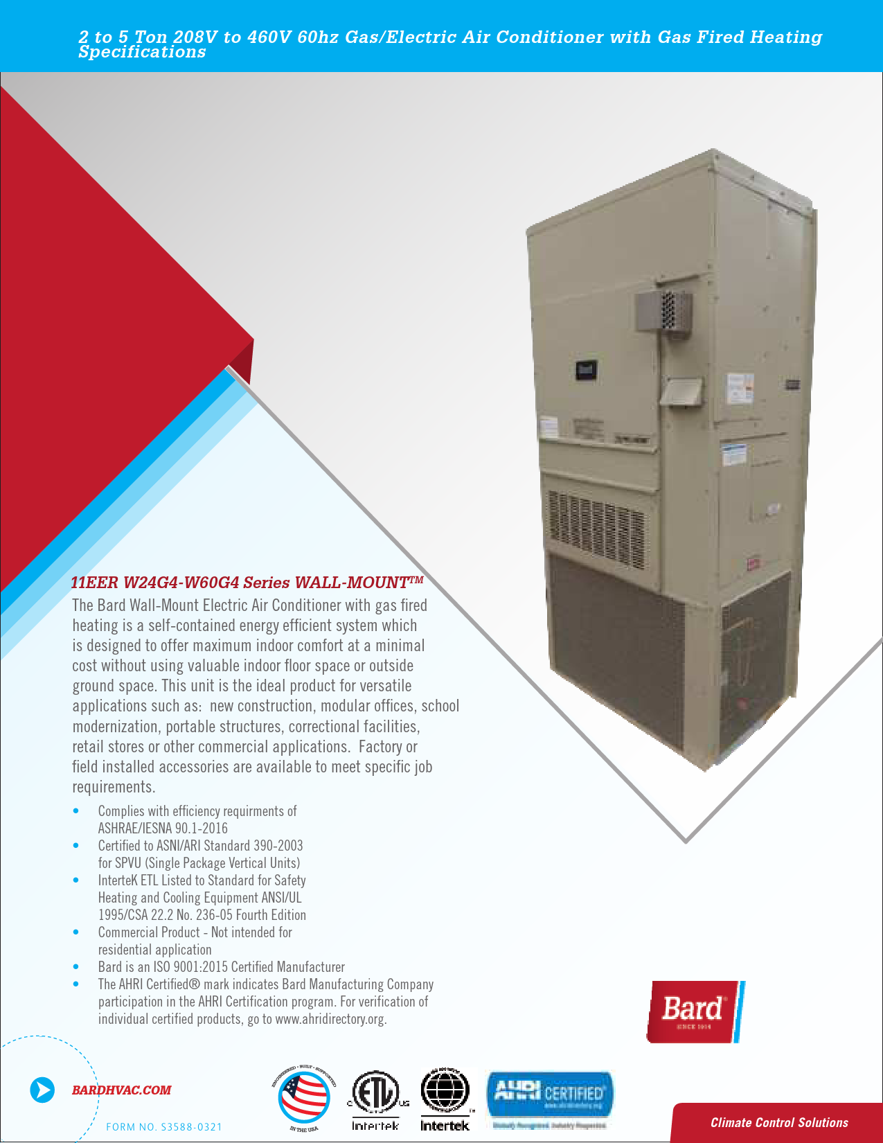
Bard WALL-MOUNT™ Series
2 to 5 Ton Gas/Electric Air Conditioner with Gas Fired Heating
The Bard WALL-MOUNT™ series offers a self-contained, energy-efficient solution for commercial climate control, combining electric air conditioning with reliable gas-fired heating. Designed to maximize indoor comfort while minimizing the need for valuable indoor floor space or outdoor ground space, these units are ideal for a wide range of applications.
Key Features & Applications:
- Versatile installation for new construction, modular offices, school modernization, correctional facilities, retail stores, and more.
- High efficiency cooling and gas heating capabilities.
- Compliance with ASHRAE/IESNA 90.1-2016 and certified to ARI Standard 390-2003.
- Advanced features like ECM indoor blower motors and scroll compressors for quiet, efficient operation.
- ISO 9001:2015 Certified Manufacturer.
Explore the comprehensive specifications and performance data for models ranging from 2 to 5 tons. For more details, visit BardHVAC.com.
Models: Bard, Gas Electric Air Conditioner, Gas Fired Heating
Full PDF Document

If the inline viewer fails, it will open the original document in compatibility mode automatically. You can also open the file directly.