JVC GY-HC550/GY-HC500 Series
4K Memory Card Camera Recorder - Basic Instructions
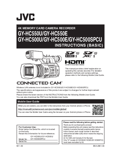
This document provides a brief overview of the JVC GY-HC550 and GY-HC500 series 4K Memory Card Camera Recorders. It covers essential setup, shooting procedures, playback, and network functions.
Key models include: GY-HC550U, GY-HC550E, GY-HC500U, GY-HC500E, and GY-HC500SPCU.
For detailed operation methods and camera settings, users are directed to the comprehensive Mobile User Guide, available online:
http://manual3.jvckenwood.com/pro/mobile/global/
Important safety instructions and precautions are also detailed within this manual to ensure safe and effective use of the equipment.
Models: 4K Memory Card Camera Recorder, GY-HC550U, GY-HC550E, GY-HC500SPCU
Full PDF Document

If the inline viewer fails, it will open the original document in compatibility mode automatically. You can also open the file directly.