QSN-4A5-D SPEC (3691173)
QSN-4A5-D SPEC (3691173)
Lutron, Energi Savr Node, Athena, RTISS, Quantum, Auto-detect, auto detect, 369-1173, 3691173, QSN-4A5-D, QSN-4A5-D SPEC (3691173)
Lutron;, Energi, Savr, Node;, Athena;, RTISS;, Quantum;, Auto-detect;, auto, detect;, 369-1173;, 3691173;, QSN-4A5-D;, QSN-4A5-D, SPEC, (3691173)
Energi Savr Node PRO LED Phase Adaptive Power Module
SPECIFICA AL Page Job Name: Job Number: Model Numbers: Energi Savr Node QSN-4A5-D PRO LED Phase Adaptive Power Module 3691173b 2 04.07.21 HN 4
SPECIFICA AL Page ob Name: ob Number: Model Numbers: Energi Savr Node QSN-4A-D PRO LED Phase Adaptive Power Module 3691173b 4 04.07.21 Specifications (continued) Output Zone Ratings (continued) Each zone is rated for th…
Energi Savr Node PRO LED Phase. Adaptive Power Module. The Energi Savr Node (ESN) family is a group of modular products for the control of lighting loads ...
Extracted Text
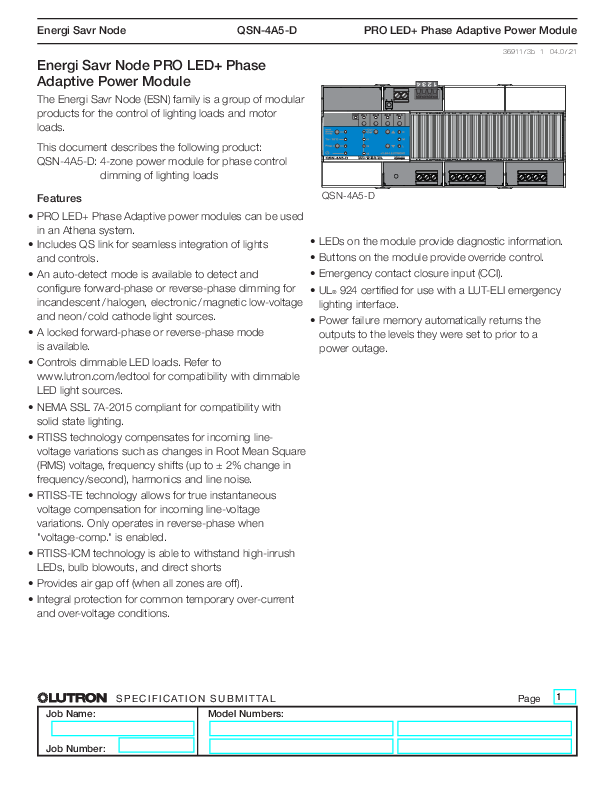
Energi Savr Node

QSN-4A5-D

PRO LED+ Phase Adaptive Power Module

Energi Savr Node PRO LED+ Phase Adaptive Power Module
The Energi Savr Node (ESN) family is a group of modular products for the control of lighting loads and motor loads.

This document describes the following product: QSN-4A5-D: 4-zone power module for phase control
dimming of lighting loads

3691173b 1 04.07.21

Features

QSN-4A5-D

� PRO LED+ Phase Adaptive power modules can be used

in an Athena system. � Includes QS link for seamless integration of lights
and controls.

� LEDs on the module provide diagnostic information. � Buttons on the module provide override control.

� An auto-detect mode is available to detect and

� Emergency contact closure input (CCI).

configure forward-phase or reverse-phase dimming for � UL� 924 certified for use with a LUT-ELI emergency

incandescent/halogen, electronic/magnetic low-voltage lighting interface.

and neon/cold cathode light sources.

� Power failure memory automatically returns the

� A locked forward-phase or reverse-phase mode

outputs to the levels they were set to prior to a

is available.

power outage.

� Controls dimmable LED loads. Refer to

www.lutron.com/ledtool for compatibility with dimmable

LED light sources.

� NEMA SSL 7A-2015 compliant for compatibility with solid state lighting.

� RTISS technology compensates for incoming linevoltage variations such as changes in Root Mean Square (RMS) voltage, frequency shifts (up to � 2% change in frequency/second), harmonics and line noise.

� RTISS-TE technology allows for true instantaneous voltage compensation for incoming line-voltage variations. Only operates in reverse-phase when "voltage-comp." is enabled.

� RTISS-ICM technology is able to withstand high-inrush LEDs, bulb blowouts, and direct shorts

� Provides air gap off (when all zones are off).

� Integral protection for common temporary over-current and over-voltage conditions.

� SPECIFICATION SUBMITTAL

Job Name:

Model Numbers:

Job Number:

Page 1

Energi Savr Node

QSN-4A5-D

PRO LED+ Phase Adaptive Power Module

System Example
Emergency Contact Closure Input
Adaptive Power Module

3691173b 2 04.07.21

Palladiom seeTouch QS Keypad Wallstation ESN Power
Module

Athena Light Management Hub (QP5)

Wired Daylight Sensors (up to 4)

Wired Occupancy
Sensors (up to 4)

CCI COM MUX MUX COM 0-10 V 50 mA

5/16 in 8 mm

4.4 in-lb 0.5 N � m

Zn 1 Zn 2 Zn 3 Zn 4

Input | Entrada Entr�e

HomeWorks QS

Tc  65 �C LQSE-4T5-120-D

Prog

120 V~ 50 / 60 Hz

lutron.com

Def

1

2

120 V~ 5 A ea

3

H Opt
M
L

H

N

1

2

3

4

QS Link

Athena LTE Modem

Wired Wallstation or IR Receivers
(up to 4)
OR OR

IR Transmitter


120/277 V~ Control Power 800 W Adaptive load1
500 W Adaptive load1 500 W Adaptive load1 500 W Adaptive load1

QSM

QS Contact QS Shade Closure
Interface

Radio Powr Savr Occupancy Sensor (up to 10 per QSM)

Pico Wireless Controller (up to 10 per QSM)

Radio Powr Savr Daylight Sensor (up to 10 per QSM)

Notes: 1 See "Output Zone Ratings" in "Specifications" section, for specific load types ratings. 2 Up to 4 wired sensors total (of any type) per QSM. 3 The maximum number of daylight sensors (wired and wireless) that an ESN module can support is 4 (1 per zone).

� SPECIFICATION SUBMITTAL

Job Name:

Model Numbers:

Job Number:

Page 2

Energi Savr Node

QSN-4A5-D

PRO LED+ Phase Adaptive Power Module

Specifications
Adaptive Power Module

3691173b 3 04.07.21

Power � 120 V~ 50/60 Hz, 16 A maximum total input current � 277 V~ 50/60 Hz, 8.3 A maximum total input current � Lightning strike protection meets ANSI/IEEE standard
62.31-1980. Can withstand voltage surges of up to 6000 V and current surges of up to 3000 A.
Regulatory Approvals
� Lutron Quality Systems registered to ISO 9001.2015 � cULus Listed � NOM Certified � ICES-5(B)/NMB-5(B) � FCC Class B � UL� 924 � NEMA SSL 7A-2015
Environment � See Mounting on page 6 for thermal specifications. � Relative humidity: less than 90% non-condensing. � For indoor use only.
Output Zone Ratings � Each zone has no minimum load requirement. � When programmed to "auto detect" mode, the module
starts in reverse-phase and if an incompatible load is detected, it will convert to forward-phase. � Internal relay provides an air gap off when all zones are off. � One load type per zone. � Output must not be used to control receptacles. If controlling plug-in lamps, installation must ensure a method of preventing non-rated loads being plugged into the module. An example is a dedicated receptacle with an alternate plug load such as a Duplex Dimming Receptacle (NTR-15-DDTR-WH) and Dimming Lamp Plug (RP-FDU-10-WH). For a full model list, please refer to Lutron P/N 369269 at www.lutron.com

� Output must be directly connected to the load.
� Output breakers or switches must not be used.
� Run a separate neutral for each load circuit. A common neutral connection is not recommended.
� The module may be powered by Ground Fault Circuit Interrupter (GFCI) or Arc Fault Circuit Interrupter (AFCI) if required. If using a GFCI or an AFCI incorporating GFCI protection, maximum wire length between the module and the load must be less than 100 ft (30 m). Load circuit wiring (from breaker to module to load) must be run in its own non-metallic conduit, or nuisance tripping may occur.
� For applications requiring 0�10 V- control, use Ten Volt Interface (GRX-TVI) or the QSN-4T5-120-D.
� For applications requiring higher wattage ratings, use a power booster (PHPM-PA-120-WH, PHPM-PA-DV-WH, or PHPM-PA-277/DV).
� For dimmable loads only. For applications requiring switching control, use a PHPM-SW-DV-WH interface or the QSN-4S8-120-D.
� Works up to the output current rating with all dimmable LED drivers whose inrush current does not exceed NEMA410 standards for electronic ballast/driver.

� SPECIFICATION SUBMITTAL

Job Name:

Model Numbers:

Job Number:

Page 3

Energi Savr Node

QSN-4A5-D

PRO LED+ Phase Adaptive Power Module

Specifications (continued)

Output Zone Ratings (continued)

Each zone is rated for the following wattage and load typesA, B:

120 V~ Ratings: 16 A maximum per module

Load Type

Zone 1 Rating

LED (reverse-phase)B

6.6 A

Lutron Hi-lume A-series LTEF

4.0 A (20 drivers maximum)

LED SSL7A-2015 (forward-phase)E 400 W

Incandescent/Halogen, ELV

800 W

Neon/Cold Cathode, MLVD

800 VA (525 WC)

277 V~ Ratings: 8.3 A maximum per module

Load Type

Zone 1 Rating

LED (reverse-phase)B

2.9 A

Incandescent/Halogen, ELV

800 W

Neon/Cold Cathode, MLVD

800 VA (525 WC)

Zone 2, 3 and 4 Rating (per zone) 4.2 A 3.0 A (13 drivers maximum) 200 W 500 W 500 VA (375 WC)
Zone 2, 3 and 4 Rating (per zone) 1.8 A 500 W 500 VA (375 WC)

3691173b 4 04.07.21

AAdditional load type options are available in the programming software suite, some may require an interface. Contact Lutron for details. BWorks with all dimmable LED drivers whose inrush current does not exceed NEMA410 standards for electronic ballast/drivers. Refer to
www.lutron.com/ledtool for specific LED compatibility information and recommended LED light sources. CActual lamp wattage. D Only use iron core transformers intended for use with an electronic switch or dimmer per Clause 8.3 of IEC/EN 60669-2-1. E Complies with SSL7A-2015 when configured in the programming software suite to LED forward phase with low-end trim set to 10% and high-end trim set
to 90%.
F Load type must be set to "Hi-lume 1% 2-Wire LTE LED", with low-end trim = 32% and high-end trim = 78%. Setting the proper trim and load type is necessary to ensure optimal performance and 1% dimming capability.

� SPECIFICATION SUBMITTAL

Job Name:

Model Numbers:

Job Number:

Page 4

Energi Savr Node

QSN-4A5-D

PRO LED+ Phase Adaptive Power Module

Specifications (continued)

Out of Box Functionality

3691173b 5 04.07.21

Terminals (Torque, wire gauge & type ratings)

� Mains wiring: 5 in-lbs (0.6 N�m) 14 AWG to 10 AWG (2.5 mm� to 4.0 mm�) (single wire, solid or stranded)
� Zone wiring: 5 in-lbs (0.6 N�m) 14 AWG to 10 AWG (2.5 mm� to 4.0 mm�) (single wire, solid or stranded)

� CCI wiring: 5 in-lbs (0.6 N�m) 20 AWG to 10 AWG (0.5 mm� to 4.0 mm�) (single wire, solid or stranded)

20 AWG to 16 AWG (0.5 mm� to 1.5 mm�)

(two wires, solid or stranded)

� QS link:

5 in-lbs (0.6 N�m)

Power (terminal 1): 22 AWG to 12 AWG (0.25 mm2 to 2.5 mm2)
(single wire, solid or stranded)

22 AWG to 18 AWG (0.25 mm2 to 1 mm2) (two wires, solid or stranded)

Data (terminals 3 and 4): 1 pair, twisted and screened,

22 AWG to 12 AWG (0.25 mm2 to 2.5 mm2) (single wire, solid or stranded)

22 AWG to 18 AWG (0.25 mm2 to 1 mm2) (two wires, solid or stranded)

Programming and Compatibility Requirements � S etup and programming of the Phase Adaptive Power
Module is done through the Athena programming software. � Athena software version 20.4 or higher is required.
QS Link Limits � Each power module counts as one device toward the QS link
device limit, and four switchlegs toward the switchleg limit.

This section describes the default functionality when the module is first installed.
Emergency Contact Closure Input (CCI)
� When the CCI is open, the module will enter emergency mode, which will turn on all loads to their emergency level and disable control of local zones and QS devices.
� When the CCI is closed or jumpered, zones will return to the settings or levels they were at prior to entering emergency mode. Note: Unit will process any sensor events received while in emergency mode after it exits emergency mode.
Normal Mode Operation
� By default each zone is set to an Auto Detect load type with ON and OFF control only. Each zone will turn load ON or OFF until it is configured via module programming.
� Zone and raise/lower buttons on the unit can be used to: � Turn loads ON and OFF. � Dim loads up and down after they are configured in programming utility.

� SPECIFICATION SUBMITTAL

Job Name:

Model Numbers:

Job Number:

Page 5

Energi Savr Node

QSN-4A5-D

Mounting
� Module is 12 DIN modules wide, 8.5 in (216 mm). � Mount in a Lutron DIN panel (see Lutron specification
submittal 3691183 at www.lutron.com). � Mount module in orientation shown. � Mount to DIN rail by pressing the module onto the rail
with the clips locked. To remove from rail, unlock clips using a screwdriver. � Mount the module where audible noise is acceptable (internal relays click). � Mount in an accessible and serviceable location. � The module generates heat, maximum 75 BTUs/Hour. � Mount module such that all the conditions below are met: � Room ambient temperature is between 32 �F and
104 �F (0 �C and 40 �C) � Calibration point maximum: 158 �F (70 �C)

PRO LED+ Phase Adaptive Power Module
3691173b 6 04.07.21


Locked

Unlocked

4 mounting clips on unit

Mechanical Dimensions

Left Side View

Front View

Calibration point


3.54 in (90 mm) 3.54 in (90 mm)

2.17 in (55 mm)
2.75 in (70 mm)
2.99 in (76 mm)

� SPECIFICATION SUBMITTAL

Job Name:

Model Numbers:

Job Number:

8.50 in (216 mm)

Page 6

Energi Savr Node

QSN-4A5-D

Overview of Wiring Terminals

Emergency

Contact Closure Input (CCI)

QS Link

PRO LED+ Phase Adaptive Power Module
3691173b 7 04.07.21

CCI COM
MUX MUX COM


LL

NNNNN

DL1 DL2 DL3 DL4

Mains Input

Load Neutrals

Mains Wiring

Zone Zone 13
Zone Zone 24
Phase Adaptive Outputs

� SPECIFICATION SUBMITTAL

Job Name:

Model Numbers:

Job Number:

Page 7

Energi Savr Node

QSN-4A5-D

PRO LED+ Phase Adaptive Power Module

Verify Wiring

3691173b 8 04.07.21

� Apply power to loads to identify any load or wiring faults prior to connecting loads to the module.
� Reference the Lutron panel spec sheets 3691183 at www.lutron.com for alternate wiring verification method. Optional pre-stripped wiring harness sold separately, Lutron P/N PDW-D-DV.

� To verify wiring:
1. Turn off power. 2. Connect loads directly to Line/Hot to bypass
the module and protect it from wiring faults. 3. A pply power, ensure the desired loads are
powered and properly wired. 4. T urn off power and connect loads to DL
terminals on module for normal operation.

CCI COM
MUX MUX COM

Neutral
N N N N N
DL DL
4X Loads
DL DL
Hot
H


LL

NNNNN

DL1 DL2 DL3 DL4

Bypass jumper pre-installed in Lutron panels

� SPECIFICATION SUBMITTAL

Job Name:

Model Numbers:

Job Number:

Page 8

Energi Savr Node
Mains Voltage Wiring

QSN-4A5-D

PRO LED+ Phase Adaptive Power Module
3691173b 9 04.07.21


Neutral

N N N N N

DL

4X Loads

DL

DL

DL
Hot
H

LL

NNNNN

Zone 1 Example
DL1 DL2 DL3 DL4

Wiring from Distribution to Module � Turn off all circuit breakers or isolators feeding the
module at distribution panel. � Run line/hot, neutral, and earth ( ) wires from a
120/277 V~ 50/60 Hz feed to the module. � Run a separate neutral for each load circuit.
Mains Wiring and NECR Class 2 Separation � Follow appropriate local and national codes to ensure
proper separation.

� SPECIFICATION SUBMITTAL

Job Name:

Model Numbers:

Job Number:

Page 9

Energi Savr Node

QSN-4A5-D

PRO LED+ Phase Adaptive Power Module

Wiring: Emergency Contact Closure Input

800 W Max 500 W Max 500 W Max 500 W Max Input
S1 S2 S3 S4 CCI Zone 1 Zone 2 Zone 3 Zone 4 Type

IR Photo Occ Switch

Option

Input

Def

H

H i Temp Prog

Opt1

M

Opt2

L

DIN Rail Power Module
QSNE-4A-D

Power

Opt3

230 V~ 50 / 60 Hz 10 A

www.lutron.com +44.(0)20.7702.0657

Common CCI

Note: Shown with pre-installed jumper.

CCI COM

00 W Max 500 W Max 500 W Max 500 W Max
Zone 1 Zone 2 Zone 3 Zone 4

Option

Def

H

Opt1

M

Opt2

L

Opt3

www.lutron.com +44.(0)20.7702.0657

3691173b 10 04.07.21
NECR Class 2 Contact Closure Input
� Contact closure input (CCI) wiring is NEC� Class 2.
� Follow all applicable national and local codes for proper circuit separation and protection.
� Turn off all breakers or isolators feeding the module at distribution panel before servicing unit.
� The CCI is a local control only and cannot control other units over the QS link. A maximum of 32 units may be connected in parallel to a CCO device (LUT-ELI-3PH) if the event is intended to affect multiple devices. Refer to Lutron's Emergency Lighting Application Note #106 (P/N 048106) on www.lutron.com for details.
� When in emergency mode, all zone outputs will be at their programmed emergency light level (configurable for each zone, default is 100%). All sensors and controls are locked out.
� Contact Closure Input is normally closed (NC). The unit is shipped with a jumper pre-installed.
Note: The unit will default to emergency mode if the CCI is left open. If no contact closure input is required, leave the wire jumper in the CCI terminals.

� SPECIFICATION SUBMITTAL

Job Name:

Model Numbers:

Job Number:

Page 10

Energi Savr Node

QSN-4A5-D

PRO LED+ Phase Adaptive Power Module

Wiring: QS Link


3691173b 11 04.07.21
QS Link NECR Class 2 Wiring � Follow all applicable national and local codes for proper
circuit separation and protection. � Link communicates using NECR Class 2 wiring. � Device does not supply or consume PDUs. � Wiring may be daisy-chained or T-tapped. � Do NOT connect terminal 2. � Optional QS link wiring harnesses sold separately, refer
to Lutron specification submittal 3691183 on www.lutron.com for part numbers.

MUX MUX COM

(1) COM (2) Do Not Connect (3) MUX (4) MUX
Daisy-Chain Wiring Example

QS Link Wiring Options

Control Link
Length
Less than 500 ft (153 m)
500 ft (153 m) to 2000 ft (610 m)

Wire Gauge (for terminals)
Power (terminals 1 and 2): 1 pair 18 AWG (1.0 mm2)
Data (terminals 3 and 4): 1 pair 22 AWG (0.5 mm2), twisted and screened
Power (terminals 1 and 2): 1 pair 12 AWG (4.0 mm2)
Data (terminals 3 and 4): 1 pair 22 AWG (0.5 mm2), twisted and screened

Available from Lutron
in one cable:
GRX-CBL-346S (non-plenum) GRX-PCBL-346S (plenum)
GRX-CBL-46L (non-plenum) GRX-PCBL-46L (plenum)

QS Devices

QSE-CI-DMX

T-Tap Wiring Example

QS Devices

QSE-CI-DMX
The Lutron logo, Lutron, Athena, Energi Savr Node, LED+, Palladiom, seeTouch, Radio Powr Savr, Pico, RTISS Equipped, RTISS-TE, and Hi-lume are trademarks or registered trademarks of Lutron Electronics Co., Inc. in the US and/or other countries. All other product names, logos, and brands are property of their respective owners.

� SPECIFICATION SUBMITTAL

Job Name:

Model Numbers:

Page 11

Job Number: