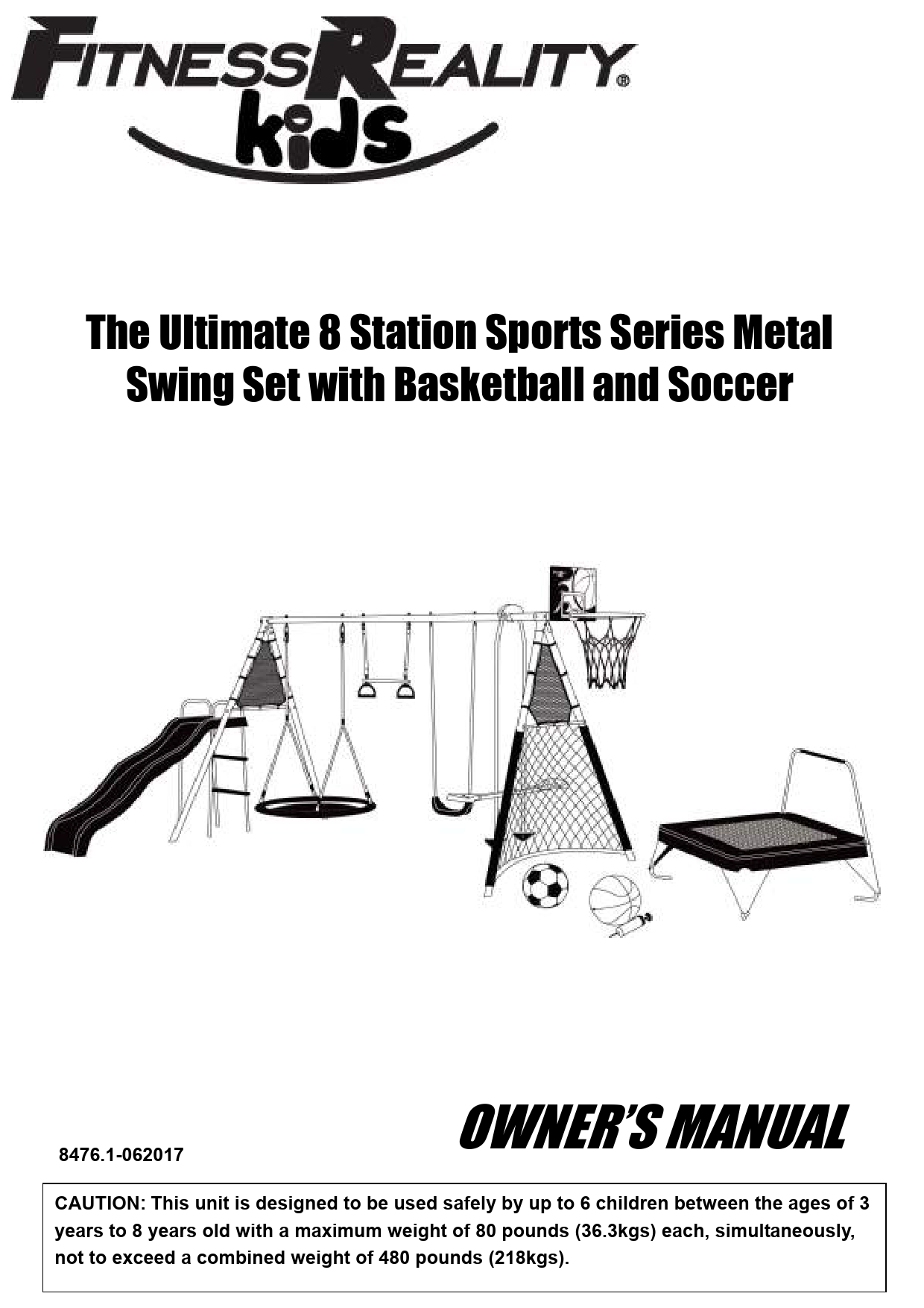
The Ultimate 8 Station Sports Series Metal Swing Set with Basketball and Soccer
Model Number: 8476.1-062017
CAUTION: This unit is designed to be used safely by up to 6 children between the ages of 3 years to 8 years old with a maximum weight of 80 pounds (36.3kgs) each, simultaneously, not to exceed a combined weight of 480 pounds (218kgs).
Important Information
PLEASE DO NOT RETURN THIS PRODUCT TO THE STORE.
STOP. Contact customer service if you have any questions regarding assembly or proper operation of the machine.
Email us at: Service@paradigmhw.com
Or call us at: 1-844-641-7920
Hours: 8:00 am to 5:00 pm (PST) Daily
Table of Contents
Service
IMPORTANT: FOR NORTH AMERICA ONLY
For damaged or defective product, questions, replacement parts or any other service support, please contact our customer service department by the below methods:
For The Best Service, please Email: service@paradigmhw.com
Response Time: 1-2 Business Days. Emailing us with the information above will be the best method to receive a response during peak business hours.
Website: www.paradigmhw.com
Toll-Free: 1-844-641-7920
(8:00 AM - 5:00 PM Pacific Standard Time, Daily)
Response time may vary via calling.
Please have the following information ready when requesting for service:
- Your name
- Phone number
- Model number
- Serial number
- Part number
- Proof of Purchase
For damaged or defective product please contact our customer service before returning to the store.
Paradigm Health & Wellness, Inc.
1189 Jellick Ave.
City of Industry, CA 91748, USA
Label Placement
This section illustrates the placement of warning and identification labels on the swing set structure. It shows labels indicating age suitability (3-8 years), supervision requirements, and brand information.
Safety
Read all instructions carefully before assembling or operating this product. Retain this Owner's manual and keep the original purchase receipt for future reference.
- Before assembling the Fitness Playground, find level ground no less than 6 feet from any structure or obstruction. The Fitness Playground must have clearance on all sides.
- To prevent serious injury, do not allow children to play on the Fitness Playground until it is completely installed.
- Do not install the Fitness Playground over concrete, packed dirt, or any other hard surface. A fall onto a hard surface can result in serious injury.
- Only adults should assemble or disassemble this Fitness Playground.
- This product MUST be anchored.
- Adult supervision of children is required at all times when on or around this Fitness Playground.
- Never leave children unattended.
- Do not swing too high or at an angle.
- Do not hang on or climb from structural members of the Fitness Playground.
- Do not exceed the intended weight limit or maximum number of users for the Fitness Playground.
- This product is intended to be used by children between the ages of 3-8 years old.
- Be sure to observe your children and ensure that they have the strength and skills to enjoy all the rides safely before use on their own.
- Do not allow children to walk close to, behind, or in front of moving items.
- Do not allow children to twist the chains on the swing or loop them over the top bar. This may reduce the strength of the chain.
- Teach and instruct children not to swing empty seats.
- Instruct children how to sit in the center of the seats and swing with their full weight on the seat.
- Warn children not to use the equipment in any manner other than intended.
- Warn children not to get off the rides while in motion.
- Warn children to dress appropriately. Loose fitting clothing is potentially hazardous when using the Fitness Playground.
- Equipment may be slippery when wet. Do not allow children to use the equipment when wet.
- Parents should regularly check openings and surfaces, such as slides, for items that may be hazardous.
- Parents should check swing chains to ensure they are secure.
- Do not place any part of the body near moving parts.
- Never slide head first down the slide.
- Ensure that all swings and chains are secured at both ends.
- Never attach any materials that are not specifically designed for use with this swing set, such as jump ropes, pet leashes, rope or cords and other chains as these pose a potential strangulation hazard.
- Children must be supervised at all times. No playground is safe without adult supervision.
- When using the trampoline, do not perform flips, as this will increase the chances of injury. No more than one person at a time on the trampoline. Do not allow children to use without proper supervision.
- Improper usage or installation of Basketball hoop can cause serious injury.
Play Ground Rules
- Do not use equipment when wet.
- No running, pushing, shoving, or roughhousing.
- Do not use play equipment before reading manual.
- Always wear proper footwear.
Overview Drawing
The overview drawing displays a comprehensive illustration of the assembled 8-station swing set, showcasing its various components including the main frame structure, swings, slide, basketball hoop, soccer net, and trampoline. It serves as a visual guide to the overall layout and integration of these elements.
Parts
This section lists all components required for assembly, categorized by their function and assembly group.
Parts used for main frame assembly
| Part ID | Description | Quantity |
|---|---|---|
| A1A | Top bar | 1 PC |
| A2A | Top bar | 1 PC |
| A3 | Top Bar and Legs Support | 1 PC |
| A4 | Leg | 2 PCS |
| A4A | Padded Leg | 2 PCS |
| A5 | Slide Mounting Bar | 1 PC |
| A6 | Crossbar | 1 PC |
| A7 | Basketball Hoop Support Tube | 1 PC |
| A8 | Net Bar A | 1 PC |
| A9 | Net Bar B | 1 PC |
Parts used for main frame assembly (continued)
| Part ID | Description | Quantity |
|---|---|---|
| A10 | Triangle Net | 2 PCS |
| A11 | Soccer net | 1 PC |
| A12 | Anchor | 4 PCS |
| A13 | Top Bar End Cap (Preassembled) | 1 PC |
| A14 | Leg End Cap (Preassembled) | 4 PCS |
| A15 | Crossbar Cap | 4 PCS |
| A16 | Soccer Ball | 1 PC |
| A17 | Net Anchor | 1 PC |
| A18 | Net Bar Cap | 2 PCS |
Hardware used for main frame assembly
| Part ID | Description | Quantity |
|---|---|---|
| Aa1 | Binder Post & Bolt Set (M8x15 Bolt, 10x52 Sleeve Nut) (2 Sets preassembled) | 4 SETS |
| Aa2 | Binder Post & Bolt Set (M8x15 Bolt, 10x50 Sleeve Nut) | 2 SETS |
| Aa3 | Binder Post & Bolt Set (M6x12 Bolt, 8x48 Sleeve Nut) | 12 SETS |
| Aa4 | Binder Post & Bolt Set (M6x12 Bolt, 8x45 Sleeve Nut) | 4 SETS |
Parts used for basketball board assembly
| Part ID | Description | Quantity |
|---|---|---|
| B1 | Basketball Hoop Support Tube A | 1 PC |
| B2 | Basketball Hoop Support Tube B | 1 PC |
| B3 | Basketball Hoop | 1 PC |
| B4 | Basketball backboard | 1 PC |
| B5 | Basketball | 1 PC |
| B6 | Air Pump | 1 PC |
Hardware used for basketball board assembly
| Part ID | Description | Quantity |
|---|---|---|
| Aa3 | Binder Post & Bolt Set (M6x12 Bolt, 8x48 Sleeve Nut) | 1 SET |
| Ba2 | Bolt Set (M6x15 Bolt) | 5 SETS |
Parts used for nest swing seat assembly
| Part ID | Description | Quantity |
|---|---|---|
| C1 | Nest Swing Seat Rail | 4 PCS |
| C2 | Nest Swing Seat Net | 1 PC |
| C3 | Nest Swing Seat Rope | 2 PCS |
Hardware used for nest swing seat assembly
| Part ID | Description | Quantity |
|---|---|---|
| Ca1 | J-Bolt Set (10 x 30 Sleeve Nut) | 2 SETS |
| Ca2 | Nut Cap Set | 4 SETS |
Parts used for trapeze assembly
| Part ID | Description | Quantity |
|---|---|---|
| E1 | Trapeze Ring Hanger Handle (Preassembled) | 2 SETS |
| E2 | Trapeze Ring Tube | 1 PC |
| E3 | Cap for Trapeze Ring Tube (Preassembled) | 2 PCS |
Hardware used for trapeze assembly
| Part ID | Description | Quantity |
|---|---|---|
| Ea1 | Sleeve Nut Set (Preassembled) | 2 SETS |
| Ea2 | Eye Bolt Set (Preassembled) | 2 SETS |
| Ea3 | Screw Hook (Preassembled) | 2 PCS |
| Ea4 | Cap Nut Set (Preassembled) | 2 SETS |
Parts used for swing seats assembly
| Part ID | Description | Quantity |
|---|---|---|
| J1 | Swing Chain (Preassembled on the seat) | 2 PCS |
| J2 | Swing Seat | 1 PC |
Hardware used for swing seats assembly
| Part ID | Description | Quantity |
|---|---|---|
| Ja1 | Female Bolt Set (Preassembled) | 2 SETS |
| Ja2 | Eye Bolt Set (Preassembled) | 2 SETS |
| Ja3 | Screw Hook (Preassembled) | 2 PCS |
| Ja4 | Screw Hook Cap Set (Preassembled) | 2 SETS |
Parts used for glider assembly
| Part ID | Description | Quantity |
|---|---|---|
| D1 | Glider Vertical Pole | 2 PCS |
| D2 | Glider Horizontal Pole | 2 PCS |
| D3 | Foot Rest | 2 PCS |
| D4 | Glider Seat | 2 PCS |
| D5 | Glider Attachment | 1 PC |
| D6 | Glider Vertical Pole Cap | 4 PCS |
Hardware used for glider assembly
| Part ID | Description | Quantity |
|---|---|---|
| Da1 | Binder Post & Bolt Set (M6x12 Bolt, 8x73 Sleeve Nut) | 2 SETS |
| Da2 | Bolt Set (M6x40 Bolt) | 2 SETS |
| Da3 | Bolt Set (M6x38 Bolt) | 4 SETS |
| Da4 | Binder Post & Bolt Set (M6x12 Bolt, 8x40 Sleeve Nut) | 2 SETS |
| Da5 | Glider Bolt Set (10x30 Sleeve Nut) | 1 SET |
Parts used for slide assembly
| Part ID | Description | Quantity |
|---|---|---|
| Z1 | Slide Ladder Support Tube | 1 PC |
| Z2 | Slide Ladder Connecting Tube | 1 PC |
| Z3 | Slide Leg Tube | 2 PCS |
| Z4 | Slide Ladder Step | 2 PCS |
| Z5 | Connecting Plate | 2 PCS |
| Z6 | Cap for Z1 and Z2 (Preassembled) | 2 PCS |
| Z7 | Cap for Z3 (Preassembled) | 2 PCS |
| Z8 | Slide | 1 PC |
| Z9 | Slide Ladder Support Tube Cross Bar | 2 PCS |
| Z10 | Slide Leg Cross Bar | 1 PC |
| Z11 | Crossbar Cap | 10 PCS |
Hardware used for slide assembly
| Part ID | Description | Quantity |
|---|---|---|
| Za1 | Bolt Set (M6x36 Bolt) | 4 SETS |
| Za2 | Bolt Set (M6x42 Bolt) | 4 SETS |
| Za3 | Binder Post & Bolt Set (M6x12 Bolt, 8x24 Sleeve Nut) | 10 SETS |
Parts used for trampoline assembly
| Part ID | Description | Quantity |
|---|---|---|
| S1 | Spring | 24 PCS |
| S2 | Jump Mat | 1 PC |
| S3 | Frame Pad | 1 PC |
| S4A | L-Shaped Tube (Left) | 1 PC |
| S4B | L-Shaped Tube (Right) | 1 PC |
| S5 | Straight tube | 1 PC |
| S6 | Handlebar with Foam | 1 PC |
| S7A | Handlebar Base Tube (Left) | 1 PC |
| S7B | Handlebar Base Tube (Right) | 1 PC |
Parts used for trampoline assembly (continued)
| Part ID | Description | Quantity |
|---|---|---|
| S8 | Elbow Tube | 1 PC |
| S9 | Elbow Tube Cap (Preassembled) | 2 PCS |
| S10 | Handlebar Base Tube Cap (Preassembled) | 2 PCS |
| S11 | Anchor | 4 PCS |
Hardware used for trampoline assembly
| Part ID | Description | Quantity |
|---|---|---|
| Sa1 | Binder Post & Bolt Set (M6x12 Bolt, 8x52 Sleeve Nut) | 2 SETS |
| Sa2 | Binder Post & Bolt Set (M6x12 Bolt, 8x26 Sleeve Nut) | 2 SETS |
| Sa3 | Bolt Set (M6x32 Bolt) | 2 SETS |
Tools Required for Assembly
Prepare the following tools prior to assembling this equipment:
- Hammer: Illustrated as a claw hammer.
- Tape Measure: Illustrated as a retractable tape measure.
- Phillips Screwdriver: Illustrated as a standard Phillips head screwdriver.
- 10, 13 mm Wrench (Included): Illustrated as a combination wrench.
- Spring Loading Tool (Included): Illustrated as a tool with a hook for attaching springs.
- 5mm Allen Wrench with Phillips Screwdriver (Included): Illustrated as an Allen wrench with a Phillips head on the other end.
- 5mm Allen Wrench (Included): Illustrated as a standard Allen wrench.
Anchor Installation
For proper installation, the Anchors (A12) must be cemented into the ground. Dig a 15 x 15 x 30 cm hole at each leg. Pour cement into the hole and place the Anchor (A12) at a 5 degree angle, towards the inside of the Playground. Do not use until cement has dried.
Note: The maximum fall height for this product is 6 feet. The minimum ground clearance between the bottom of the lowest swing attachment must be 8 inches.
Must keep a minimum 8 inches of space with the soil.
Warning: Please bury the legs of the swing set as per instruction. If the swing set is used without proper anchoring, it may be dangerous and may tilt over.
This playground received ASTM F2276 and CPSIA certification.
Assembly Instructions
Step 1
Attach the Top Bar (A1A) to the Top Bar (A2A) using two Binder Post and Bolt Sets (Aa2). Tighten the Binder Post and Bolt Sets (Aa2) with the 5mm Allen Wrench provided.
Step 2
Slide the Top Bar and Legs Support (A3) over the Top Bar (A1A) and insert the Basketball Hoop Support Tube (A7) into the open end of the Top Bar (A1A). Align the holes and secure with two Binder Post and Bolt Sets (Aa1). Tighten the Binder Post and Bolt Sets (Aa1) with the 5mm Allen Wrench provided.
NOTE: Ensure that the last bolt hole of the Basketball Hoop Support Tube (A7) is outside of the Top Bar (A1A) to continue with the next step.
Step 3
Secure the Basketball Hoop (B3) to the Basketball Backboard (B4) and Basketball Hoop Support Tube (A7) using three Bolt Sets (Ba2). Tighten the Bolt Sets (Ba2) using the 5mm Allen Wrench and 10, 13 mm Wrench provided.
Step 4
Attach the Basketball Hoop Support Tube A (B1) and Basketball Hoop Support Tube B (B2) to the Basketball Backboard (B4) using two Bolt Sets (Ba2). Then attach the opposite end of the Basketball Hoop Support Tube A (B1) and Basketball Hoop Support Tube B (B2) to the Basketball Hoop Support Tube (A7) Using one Binder Post and Bolt Set (Aa3).
- Tighten the Bolt Sets (Ba2) using the 5mm Allen Wrench and 10, 13 mm Wrench provided.
- Tighten the Binder Post and Bolt Set (Aa3) with the 5mm Allen Wrench provided.
Step 5
Attach two Legs (A4) to the Top Bar (A2A) using four Binder Post and Bolt Sets (Aa3). On the Opposite side, Attach two Padded Legs (A4A) to the Top Bar and Legs Support (A3) using four Binder Post and Bolt Sets (Aa3). Then tighten all Binder Post and Bolt Sets (Aa3) using the 5mm Allen Wrench and 5mm Allen Wrench with Phillips Screwdriver provided.
NOTE: The Padded Legs (A4A) must be installed on the same side as the Basketball Hoop (B3).
Step 6
Slide a Crossbar Cap (A15) over each end of the Slide Mounting Bar (A5). Connect the Slide Mounting Bar (A5) to the two Legs (A4) using two Binder Post and Bolt Sets (Aa4). Tighten the Binder Post and Bolt Sets (Aa4) using the 5mm Allen Wrench and 5mm Allen Wrench with Phillips Screwdriver provided.
NOTE: The Slide Mounting Bar (A5) is the bar with 2 holes through the center. This will be used to attach the Slide (Z8) in later steps.
Step 7
Spread out the Soccer Net (A11) flat on the ground and find each end. Starting at the Narrowest end, weave the Soccer Net (A11) up both Padded Legs (A4A) as shown in the diagram. Then weave the Crossbar (A6) Through the top of the Soccer Net (A11) as shown in the diagram. Secure the Crossbar (A6) to the Padded Legs (A4A) using two Binder Post and Bolt Sets (Aa4). Then tighten the Binder Post and Bolt Sets (Aa4) using the 5mm Allen Wrench provided.
Step 8
Weave the Net Bar A (A8) halfway through the Soccer Net (A11) on the left side. Weave the Net Bar B (A9) halfway through the Soccer Net (A11) on the right side. Insert the tube of the Net Bar B (A9) into the Net Bar A (A8), ensure that the metal tab snaps into place.
- Secure an Anchor (A12) to the Net Bar A (A8) and Padded Leg (A4A) using a Binder Post and Bolt Set (Aa3) and Net Bar Cap (A18). Tighten the Binder Post and Bolt Set (Aa3) and Net Bar Cap (A18) using the 5mm Allen Wrench provided.
- Secure an Anchor (A12) to the Net Bar B (A9) and Padded Leg (A4A) using a Binder Post and Bolt Set (Aa3) and Net Bar Cap (A18). Tighten the Binder Post and Bolt Set (Aa3) and Net Bar Cap (A18) using the 5mm Allen Wrench provided.
Step 9
Using the Velcro straps, attach a Triangle Net (A10) to the Legs (A4) and Slide Mounting Bar (A5).
Using the Velcro straps, attach another Triangle Net (A10) to the Padded Legs (A4A) and Crossbar (A6) Using the Velcro straps.
Step 10
Attach Anchors (A12) to the ends of both Legs (A4) and Padded Legs (A4A).
Secure the Soccer Net (A11) with the Net Anchor (A17).
For proper installation, the Anchors (A12) must be cemented into the ground. Dig a 15 x 15 x 30 cm hole at each leg. Pour cement into the hole and place the Anchor (A12) at a 5 degree angle, towards the inside of the Playground. Do not use until cement has dried.
Step 11
Slide the Nest Swing Seat Rail (C1) into four of the loops of the Nest Swing Seat Net (C2). Repeat this for all four Nest Swing Seat Rails (C1). Then connect the four Nest Swing Seat Rails (C1) to the end of the previous rail. Ensure that the metal button snaps into position and is secure.
Step 12
Attach the Nest Swing Seat Ropes (C3) to the Nest Swing Seat Rails (C1) using the attached bolt and Nut Cap Sets (Ca2).
NOTE: You may have to slide back the padding of the Nest Swing Seat Rails (C1) to expose the bolt holes in the Nest Swing Seat Rails (C1).
Step 13
Install the hooked end of the Nest Swing Seat Ropes (C3) to the Top Bar (A2A) using two J-Bolt Sets (Ca1). Tighten the J-Bolt Set (Ca1) using the 5mm Allen Wrench provided.
Step 14
Slide the chain of the Trapeze Ring Hanger Handle (E1) onto the Eye Bolt Set (Ea2). Do this for both sides. Then slide the plastic cover over the hook.
Step 15
Slide the Chain of the Swing Chain (J1) onto the Eye Bolt Set (Ja2). Do this for both sides. Then slide the plastic cover over the hook.
Step 16
Attach a Foot Rest (D3) to the Glider Vertical Pole (D1) with the Bolt Set (Da2). Tighten the Bolt Set (Da2) using the 10, 13 mm Wrench provided.
Do this for both Glider Vertical Poles (D1).
Step 17
Attach the Glider Attachment (D5) onto the Top bar (A1A) with two Glider Bolt Sets (Da5). Tighten the Glider Bolt Sets (Da5) using the 5mm Allen Wrench provided.
Attach the two Glider Vertical Poles (D1) and four Glider Vertical Pole Caps (D6) onto the Glider Attachment (D5) with two Binder Post & Bolt Sets (Da4). Tighten the Binder Post & Bolt Sets (Da4) using the 5mm Allen Wrench and 5mm Allen Wrench with Phillips Screwdriver provided.
Step 18
Attach a Glider Horizontal Pole (D2) to each side of the Glider Horizontal Poles (D1) using two Binder Post and Bolt Sets (Da1). Tighten the Binder Post and Bolt Sets (Da1) using the 5mm Allen Wrench provided.
Attach a Glider Seat (D4) to both sides of the two Glider Horizontal Poles (D2) using the Bolt Sets (Da3). Tighten the Bolt Sets (Da3) using the 10, 13 mm Wrench provided.
Step 19
Insert the longer ends of the Slide Ladder Support Tube (Z1) and Slide Ladder Connecting Tube (Z2) into the holes on the rear end of the Slide (Z8) and align the holes.
Insert both Slide Leg Tubes (Z3) into the holes on the front end of the Slide (Z8) and align the holes.
Step 20
Secure the Slide (Z8) using the four Bolt sets (Za1). Then tighten using the 10, 13 mm Wrench.
Step 21
Slide the two Slide Ladder Steps (Z4) up the bottom ends of the Slide Ladder Support Tube (Z1) and Slide Ladder Connecting Tube (Z2). Align the holes of the Slide Ladder Steps (Z4) with the TOP and BOTTOM set of holes on the Slide Ladder Support Tube (Z1) and Slide Ladder Connection Tube (Z2).
Secure the Slide Ladder Steps (Z4) using four Bolt Sets (Za2), using 5mm Allen Wrench and 10, 13 mm Wrench provided.
Step 22
Attach two Connecting Plates (Z5) to the Slide Mounting Bar (A5) with two Binder Post and Bolt Sets (Za3). Tighten Binder Post & Bolt Sets (Za3) using the 5mm Allen Wrench and 5mm Allen Wrench with Phillips Screwdriver provided.
Step 23
Attach the Slide Ladder Connecting Tube (Z2) onto the Slide Mounting Bar (A5) using two Connecting Plates (Z5) and two Binder Post and Bolt Sets (Za3). Tighten Binder Post & Bolt Sets (Za3) using the 5mm Allen Wrench and 5mm Allen Wrench with Phillips Screwdriver provided.
Step 24
Attach a Slide Ladder Support Tube Cross Bar (Z9) onto each side of the ladder using a Binder Post and Bolt set (Za3).
Attach a Slide Leg Cross Bar (Z10) to the front of the ladder using two Binder Post and Bolt Sets (Za3).
Tighten Binder Post & Bolt Sets (Za3) using the 5mm Allen Wrench and 5mm Allen Wrench with Phillips Screwdriver provided.
SECURELY TIGHTEN ALL BOLTS ON THE SLIDE
Step 25
Insert the small ends of the L-Shaped Tube (Left) (S4A) and L-Shaped Tube (Right) (S4B) into the sockets of the Elbow Tube (S8). The welded bracket of the L-Shaped Tube (Left) (S4A) and L-Shaped Tube (Right) (S4B) should face outwards.
Insert the small end of the Straight Tube (S5) into the opening of the L-Shaped Tube (Left) (S4A) and L-Shaped Tube (Right) (S4B).
Align the holes and secure with two Binder Post and Bolt Sets (Sa3). Then tighten using the 5mm Allen Wrench and 10, 13mm Wrench provided.
Step 26
Align the Handlebar Base Tube (Left) (S7A) to the outside of the L-Shaped Tube (Left) (S4A) align the holes and secure using a Binder Post and Bolt Set (Sa1) and a Binder Post and Bolt Set (Sa2).
Align the Handlebar Base tube (Right) (S7B) to the outside of the L-Shaped Tube (Right) (S4B) align the holes and secure using a Binder Post and Bolt Set (Sa1) and a Binder Post and Bolt Set (Sa2). Then tighten using the 5mm Allen Wrench with Phillips Screwdriver and 5mm Allen Wrench.
Step 27
Lay out the Jump Mat (S2) and align the triangle rings of the mat with the holes in the L-Shaped Tube (Left) (S4A) and the L-Shaped Tube (Right) (S4B).
Attach a Spring (S1) with the hook facing down, onto the triangle ring of the Jump Mat (S2). Hold the Spring loading tool underhand and pull the spring hook towards the holes on the surrounding frame. Drop the hook into the frame hole until it latches on. Do this for all Springs (S1) and Triangle Rings.
NOTE: Be careful not to pinch hands or fingers on Springs (S1). Wear gloves to prevent pinching. Keep Springs (S1) Dry, Wet Springs are very slippery.
Step 28
Slide the front two corners of the Frame Pad (S3) over the L-Shaped Tube (Left) (S7A) and L-Shaped Tube (Right) (S7B).
Lay the Frame Pad (S3) over the trampoline so that the Springs (S9) and the steel frame are covered. Ensure that the Frame Pad (S3) covers all metal parts.
Step 29
Slide the Handlebar (S6) onto the small ends of the L-Shaped Tube (Left/Right)(S7A/S7B). Ensure that the pop pins set into place.
TIGHTEN ALL HARDWARE AT THIS TIME!
Step 30
Tie the straps of the Frame Pad (S3) to the triangle rings with a knot. Repeat this for all straps. Make sure the knots are tight and that the Frame Pad (S3) fits securely over the trampoline.
Place the trampoline in the desired location and secure it with the Anchors (S11). Ensure that the hooked end of the Anchors (S11) is securely attached to the frame.
Step 31
Use the Air Pump (B6) to Pump up the Basketball (B5) and Soccer Ball (A16).
There is an inflation needle stored in the handle of the Air Pump (B6).
Warranty
MANUFACTURER'S LIMITED WARRANTY
Paradigm Health & Wellness warrants to the original purchaser that this product is free from defects in material and workmanship when used for the purpose intended, under the conditions that it has been installed and operated in accordance with Paradigm's Owner's Manual. Paradigm's obligation under this warranty applies to the following:
| COMPONENT | LENGTH OF WARRANTY |
|---|---|
| Structural Frame | 2 years |
| All Other Components | 180 days |
Exclusions from Warranty Coverage:
Paradigm does not warrant against and is not responsible for, and no implied warranty shall be deemed to cover, any product failure, product malfunction, or damages attributable to:
- Improper installation and/or failure to abide by Paradigm's installation guidelines;
- Use of this product beyond normal home use, or in an application for which it was not designed;
- Cosmetic items such as scratches, dents or discolorations;
- Damage caused by normal wear and tear, vandalism, accidental or by animals;
- Any act of Nature (such as fire, flooding, snow, ice, hurricane, earthquake, lightning or other natural disaster), environmental condition (such as air pollution, mold, mildew, etc.), or staining from foreign substances (such as dirt, grease, oil, etc.);
- Normal weathering due to exposure to sunlight, weather and atmosphere which can cause colored surfaces to, among other things, flake, chalk, accumulate dirt or stains.
- Improper operation, alteration, handling, storage, abuse or neglect of the products.
Paradigm, using its sole discretion, will either repair or replace free of charge any part(s) proven to be defective under normal home use. Any repair or replacement shall provide no new warranty coverage, but shall retain only the remaining portion of the original product's warranty. This warranty is offered only to the original purchaser and is not transferable. Proof of original purchase is required.
Ordering Replacement Parts
Replacement parts can be ordered by emailing our customer service department:
Email: Service@paradigmhw.com
Open Daily 8:00 AM - 5:00 PM (PST).
When ordering replacement parts please have the following information ready:
- Owner's Manual
- Model Number
- Description of Parts
- Part Number
- Date of Purchase
Parts Request Form
Paradigm Health & Wellness, Inc.
EMAIL THIS FORM WITH YOUR RECEIPT OF PURCHASE TO: Service@paradigmhw.com
"YOUR ORDER WILL BE PROCESSED WITHIN 3 BUSINESS DAYS"
*This form can also be faxed to #: 626-810-2166
