HV-Adapterset
File info: application/pdf · 18 pages · 2.93MB
HV-Adapterset
VAS 6558A/35 - VW Authorized Tools and Equipment
Environment. Make sure that the tool set is set up in a work area that is free from sources of heat (max. 50°C / 122°F), corrosive liquids, greases and.
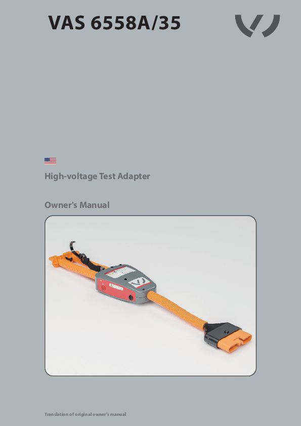
VAS 6558A/35
Full PDF Document

If the inline viewer fails, it will open the original document in compatibility mode automatically. You can also open the file directly.
Extracted Text
VAS 6558A/35
High-voltage Test Adapter Owner's Manual
Translation of original owner's manual

?

Owner's Manual
VAS 6558A/35
Hochvolt-Pr�fadapter Betriebsanleitung
Originalbetriebsanleitung

USB flash drive

www.tkrgroup.com/service

1. Digital owner's manual Europe

1. Technical support
2. Download current owner's manuals
Europe

Worldwide

Worldwide

2

1. Safety

1.1

General instructions

4

1.2

Explanation of symbols

5

1.3

Markings

5

1.4

Scope of supply

6

1.5

Safety instructions

6

2. Technical data

2.1

Device components

8

2.2

Operating conditions

8

2.3

Technical data

9

3. Use

3.1

Intended use

10

3.2

Principles for handling the high-voltage test adapter

10

3.3

Function test of high-voltage test adapter VAS 6558A/32

11

3.4

Insulation resistance measurement

14

4. Maintenance

4.1

Troubleshooting

14

4.2

Maintenance

15

5. Service

5.1

Disposal

16

5.2

Warranty & Service

16

5.3

EU Declaration of Conformity

17

This owner's manual is protected by copyright. Any use outside of the boundaries of copyright law without the consent of the manufacturer is not permitted and is punishable by law. This also applies to the extraction of individual illustrations and the use of texts in excerpt form.
3

1.1 General instructions

State-of-the-art This tool represents state-of-the-art technology. To ensure the functionality of the equipment, it must be operated in a proper and safe manner.
Technical modifications In the interests of quality assurance, we reserve the unrestricted right to apply technical modifications arising out of further developments in technology and product improvements without prior notice.
Read the owner's manual Before using the tool, read the owner's manual and ensure that you have understood the instructions. This manual must always be available where the product is being used.
Handling All handling necessary to ensure correct operation is described in the owner's manual. No methods of working other than those approved by the manufacturer may be practiced.
Faults If a problem should arise, the operator may only perform actions to eliminate the problem if the relevant measure is described in the manual.
Warranty The manufacturer accepts no liability for damage or injury caused by improper repair or the use of foreign replacement parts. The warranty will not cover any damage caused to the tool due to its misuse.

5.4 Declaration of Conformity The tool has been tested and manufactured in accordance with European guidelines. The Declaration of Conformity has been included with this owner's manual.
Risk of damage to the tool The tool must only be used as described in the owner's manual. Misusing the tool or using it for any purpose for which it has not been designed is expressly prohibited. Make sure that you and your employees handle the tool properly.
Risk of injury In addition to the owner's manual, the binding provisions of the accident prevention regulations applicable at the place of use and the general (accepted) rules for safety compliance and professional working must be observed.
Qualified personnel Trained and instructed personnel have specialized training that enables them to repair/maintain the respective vehicles and vehicle components. Work on high-voltage systems may only be performed by high-voltage technicians/high-voltage experts or by professionals with equivalent or higher qualification. In addition, these workers must have documented proof that they have taken part in further training that qualifies them specifically for the tasks to be performed with the tool.

Environment Make sure that the tool set is set up in a work area that is free from sources of heat (max. 50�C / 122�F), corrosive liquids, greases and oils. Allow the tool to acclimate before start-up. Avoid the formation of condensation. For the most accurate measurement results, avoid large temperature fluctuations during measurement.

4

1.2 Explanation of symbols

In this owner's manual, some sections use internationally known warning symbols, warning notes and general instruction symbols. The individual symbols are explained below. Follow all instructions and safety rules.

Follow manual

Protective insulation

Please note the...

Observe the general information
Warning! General source of danger
High voltage! Danger to life!
Caution! Risk of explosion

Direct current (DC)

T�VRheinland

C

U S

cTUVus certification

CE marking

GS mark (Tested Safety)

Arrow to clarify compression
For more information, see section... Arrow showing direction
Product certificate https://www.tkrgroup.com/ vas-6558A-cert.htm

1.3 Markings

1.3.1
A B C

1.3.2

A

D

F

E

1.3.3

K

L

M

G

H

I

A

A

1.3.1 A B C D E

Markings on top of the high-voltage test adapter Adapter connection marking Warnings (High voltage!, Warning!, Follow manual) Manufacturer's address, contact details Part number, serial number, year of manufacture Disposal, voltage, protection class

1.3.2
A F G H I

Markings on the underside of the high-voltage test adapter Adapter connection marking Circuit diagram Inspection sticker Warning (Risk of explosion) Test certificates

1.3.3
K L M

Markings on the side of the high-voltage test adapter TP1 measuring socket + Measurement category TP1 measuring socket �

5

1.4 Scope of supply
1.4.1

O

P

R

O High-voltage test adapter P Case R USB flash drive with
owner's manual in 38 language versions and insert sheet

1.5 Safety instructions
The high-voltage test adapter is approved solely for the intended use designated by the manufacturer. The tool may only be used for the activities described in this owner's manual. Never misuse the tool. If the tool is improperly used, its safety can no longer be guaranteed.
CAUTION Risk of property damage and personal injury due to improper accessories Failure to use genuine tools or genuine accessories leads to a high safety risk. Only genuine accessories may be used. The manufacturer assumes no liability for conversions or modifications to the high-voltage test adapter.
CAUTION Risk of property damage and personal injury
6

Before performing any repair, read the safety instructions and ensure that you have understood them. Failure to read the instructions may result in serious bodily injury.
CAUTION Risk of property damage and personal injury Use of the tool by personnel who have not undergone the requisite training and instruction is prohibited. The tool must not be lent to untrained personnel. Ensure that the tool is only operated by trained personnel instructed in its use.
Ensure that the owner's manual is made available to operating personnel. This owner's manual must be carefully read and understood by each operator before they begin using it for the first time. It must always be available where the product is being used.

Observe the applicable occupational health and safety regulations of the respective country. In addition to the owner's manual, the binding provisions of the accident prevention regulations applicable at the place of use and the general accepted rules for safety compliance and professional working must be observed.
CAUTION Risk of tripping Carelessly laid supply lines/cables can lead to accidents caused by tripping, twisting (e.g. one's ankle) or tumbling or could lead to damage to the lines/cables. Route all supply lines/cables in a way that prevents them from being damaged or tripped over.
CAUTION Risk of explosion! This tool has internal arcing or sparking parts that must not come into contact with flammable vapors. This tool should be kept at least 460 mm (18 in) above the ground. The high-voltage test adapter must never be used in potentially explosive areas.
CAUTION Risk of damage to the vehicle due to a defective tool A defective tool could damage the vehicle electronics. Visually inspect the tool prior to each use. Stop using the high-voltage test adapter immediately if it is defective. Please contact Service ( 5.2).

CAUTION Risk of damage to the vehicle due to improper use Improper use can cause damage to the vehicle electronics or measurement errors. Follow the repair guide for the vehicle model in question to ensure that use of the tool does not cause damage.
CAUTION Risk of damage to the tool Improper handling of the high-voltage test adapter could damage the tool. Never throw the tool or allow it to fall.
An administrator account may be required to install the drivers.
The high-voltage test adapter may only be used at ambient temperatures of minimum 0�C / 32�F up to maximum 50�C / 122�F.

The high-voltage test adapter must not be used if any abnormalities are discovered. Please contact Service ( 5.2).
7

2.1 Device components

2.1.1.

7

8

1

6

2 3

4

6

2.1.1
1 2 3 4

High-voltage test adapter
Socket adapter A Plastic housing TP1 measuring socket + TP1 measuring socket �

5

5

Pin adapter B

6

Adapter cable

7

Hanger

8

Spring contacts

2.2 Operating conditions

Power supply No additional power supply required.
Climate conditions 2.3 Technical data
Electromagnetic compatibility (EMC) In accordance with GS 95002/GS 95024-2 (IEC61000)
DIN EN 61000-6-2 (2005) DIN EN 61000-6-3 (2007)

8

2.3 Technical data

VAS 6558A/35 Device type Fittings Supply connection Ambient temperature (operation) Ambient temperature (storage) Ambient humidity Protection: Measurement category Maximum measurement voltage Maximum current Fuse Pollution degree Safety Cable length, adapter cable

Measuring Held in the hand None (passive) 0�C to +50�C / +32�F to +122�F -20�C to +60�C / -4�F to +140�F Up to85% (non-condensing) IP20 CAT I*, CAT II**, CAT III*** 1000 V DC for CAT I, 600 V DC for CAT II, 300 V DC for CAT III 20 A 2x 20 A 1000 V super fast 2 IEC 61010-031 800 mm per side

* Measurements on circuits that have no direct connection to the network (e.g. battery operation, vehicle electrical system) ** Measurements on circuits that have a direct connection to the low-voltage network via a connector (e.g. portable electrical devices) *** Measurements within the building installation (e.g. stationary consumers with non-pluggable connection, distribution connection, sub-distribution)

2.3.1 Circuit diagram VAS 6558A/35
A B

F1 20A F2 20A

TP1

9

3.1 Intended use

High-voltage test adapter VAS 6558A/35 can be connected to test adapter VAS 6558A/32 for a function test. It is also used to measure insulation resistance at the auxiliary unit connection of the HV battery and the connected wiring harness. Use is described in the corresponding repair guide. Observe the work instructions for guided troubleshooting of the brands.
Before starting to use high-voltage test adapter VAS 6558A/35, always ensure the system is in a voltage-free state (deenergized) and check that it remains in this state for the duration of the work.

system or equipment is in a voltage-free state (deenergized) and check that it remains in this state for the duration of the work.
CAUTION Risk of injury The high-voltage test adapter may only be used with measuring devices approved by the brand (high-voltage measuring module VAS 6558A) up to including 1 kV.

As a rule, work must not be performed on live parts of electrical systems and equipment. Before starting work, ensure that the

3.2 Principles for handling the high-voltage test adapter

Risk of injury
Please ensure that the high-voltage test adapter is handled properly.
Misusing the high-voltage test adapter or using it for any purpose for which it has not been designed is expressly prohibited.
The high-voltage test adapter must only be used as described in the owner's manual.
Warranty
The manufacturer accepts no liability for damage or injury caused by improper repair or the use of foreign replacement parts.

The warranty will not cover any damage caused to the high-voltage test adapter due to its misuse.
Environment
Make sure that the high-voltage test adapter is set up in a work area that is free from sources of heat (max. 50�C/122�F), corrosive liquids, greases and oils.
Allow the tool to acclimate before start-up. Avoid the formation of condensation.
5.3 Declaration of Conformity
The high-voltage test adapter has been tested and manufactured in accordance with European guidelines. The Declaration of Conformity has been included with this owner's manual.

10

3.3 Function test of high-voltage test adapter VAS 6558A/32

Check the high-voltage adapter for damage before each use or measurement.
Visually inspect the spring contacts before each use or measurement.
To ensure that the tool is working properly, perform a function test before each use or measurement.
The function test must be performed before and immediately after use.

During the function test, the corresponding pin and socket adapter (VAS 6558A/32 with VAS 6558A/35) are connected to each other. Then perform resistance measurements with a suitable measuring device/measuring cable and compare the results with the specified reference values.
CAUTION Risk of injury If the specified reference values are not obtained during the function test, the high-voltage test adapter must not be used!

CAUTION Risk of injury No measurements may be performed if both connectors are connected to both sockets of the adapter. Only connect the socket and pin adapter on one side. Observe the specifications for the function test in Figures 3.3.1 to 3.3.5.

Visual inspection of the spring contacts
3.3.1 Visual inspection of spring contact, socket adapter A

3.3.2 Visual inspection of spring contact, socket adapter A

3

7

3.3.3 Visual inspection of spring contact, pin adapter B 3.3.4 Visual inspection of spring contact, pin adapter B

3

7

11

3.3 Function test of high-voltage test adapter VAS 6558A/32

3.3.5 Function test 1) A B
A B 3.3.6 Function test 2) A B
A B

F1 20A F2 20A

F1 20A F2 20A

F1 20A F2 20A

F1 20A F2 20A

VAS 6558A/32 R2 100k
TP1
R1 100k VAS 6558A/35
TP1

1. Connect the pin adapter to the socket adapter:

100k

Pin adapter: Connector:

VAS 6558A/32 B

Socket adapter: VAS 6558A/35

Socket:

A

2. Connect the measuring device:

Measuring probe + for VAS 6558A/32 TP1 �

Measuring probe � for VAS 6558A/35 TP1 �

Reference value: 98�102k

VAS 6558A/32 R2 100k
TP1
R1 100k VAS 6558A/35
TP1

1. Connect the pin adapter to the socket adapter:

Pin adapter: Connector:

VAS 6558A/32 B

Socket adapter: VAS 6558A/35

Socket:

A

100k

2. Connect the measuring device:
Measuring probe + for VAS 6558A/32 TP1 +

Measuring probe � for VAS 6558A/35 TP1 +

Reference value: 98�102k

12

3.3.7 Function test 3) A B
A B 3.3.8 Function test 4) A B
A B

F1 20A F2 20A

F1 20A F2 20A

F1 20A F2 20A

F1 20A F2 20A

VAS 6558A/32 R2 100k
TP1
R1 100k VAS 6558A/35
TP1

1. Connect the pin adapter to the socket adapter:

100k

Socket adapter: VAS 6558A/32

Socket:

A

Pin adapter: Connector:

VAS 6558A/35 B

2. Connect the measuring device:

Measuring probe + for VAS 6558A/32 TP1 �

Measuring probe � for VAS 6558A/35 TP1 �

Reference value: 98�102k

VAS 6558A/32 R2 100k
TP1
R1 100k VAS 6558A/35
TP1

1. Connect the pin adapter to the socket adapter:

Socket adapter: VAS 6558A/32

Socket:

A

Pin adapter: Connector:

VAS 6558A/35 B

100k

2. Connect the measuring device:
Measuring probe + for VAS 6558A/32 TP1 +

Measuring probe � for VAS 6558A/35 TP1 +

Reference value: 98�102k

13

3.4 Insulation resistance measurement

Connect HV components
Follow the repair guide for the vehicle model in question to ensure proper use.
Connect the corresponding pin/socket adapter of the high-voltage test adapter to the HV component.

DANGER Danger to life from electric shock Never connect measuring sockets TP1 + and TP1 � to each other. If there is bridging or short-circuiting, the high-voltage test adapters must be replaced immediately.
DANGER Danger to life from electric shock Work must not be performed on live parts. Always ensure the system is deenergized before starting work.

4.1 Troubleshooting

Malfunction

Problem

Remedy

The specified measurement values are There is a fault in the adapter cable (e.g. Replace the high-voltage test

not measured during the function test. due to misuse).

adapter

No measurement values are measured.

1. The fuse (in the plastic housing) is defective. 2. The spring contact pins (see visual inspection) are defective.

Replace the high-voltage test adapter

Section 3.3 � 3.4 5.2
3.3 � 3.4 5.2

14

4.2 Maintenance

Cleaning
The high-voltage test adapter is maintenance-free except for occasional cleaning with a dry, lint-free cloth.
Inspection equipment check
Use the test sticker on the high-voltage test adapter and Table 4.2.1 to check whether the measuring tool is within the prescribed test cycle.

The information regarding the test cycles corresponds to the current "actual" state.
The notes on the test equipment overview refer exclusively to Audi, VWN and VW.
Applies only to the German market: The test cycle of the high-voltage test adapter VAS 6558A/35 can be found in the current test equipment overview.

Only use measuring tools that are within the prescribed test cycle.
4.2.1 The first test date can be found on the test sticker of the high-voltage test adapter. The following tests/calibrations are due based on the table below and are performed automatically through test equipment monitoring.
4.2.1 Test dates

Audi Partner Portal (APP) The current test equipment overview can be found in the document "Test equipment overview" (navigation path: "Service > Workshop Equipment > General about workshop equipment > Measuring instrument calibration > Test equipment overview").
Volkswagen InfoNet / Volkswagen Commercial Vehicles InfoNet The current test equipment overview is found in the document "All about auditing" (Navigation path: "Overall operation > Quality & LSP > Certification & quality management") in the section "Templates and tools".

Date 1  2

Cycle After 24 months Every 12 months

Applies to all other markets: Please contact your importer if you have any questions.

15

5.1 Disposal
Machinery, equipment and their components must be disposed of as prescribed by the laws, regulations and other provisions of the country in which they are located. We recommend using licensed specialist companies for disposal. The modules and units have been developed to be environmentally compatible and suitable for recycling. According to EU Directive 2000/53/EC, these parts must be taken to an authorized collection point. The manufacturer does not promise to take back electrical equipment modules and units, complete electrical devices, or batteries free of charge.

5.2 Warranty & Service

High-voltage test adapters from TKR Spezialwerkzeuge GmbH come with a 36-month warranty for dealers against material and manufacturing defects. Otherwise, the statutory conditions governing warranty periods and our General Terms and Conditions of Sale and Supply are in force. High-voltage components are excluded.

The warranty period begins on the date of delivery to the Volkswagen Group. The date is stated on the delivery note. The warranty shall be voided if the high-voltage test adapter is used for purposes other than those for which it was designed. In addition, the warranty becomes invalid if the high-voltage test adapter is not used as described in the owner's manual. In the event of defect or fault, TKR Spezialwerkzeuge GmbH will only repair or replace faulty parts at its own discretion.

Service address

TKR Spezialwerkzeuge GmbH Service Am Waldesrand 9�11 D-58285 Gevelsberg (Germany)

Online Service

www.tkrgroup.com/service

Service e-mail

support@tkrgroup.com

16

EU Declaration of Conformity
For the purposes of the Low Voltage Directive 2014/35/EU
and the Electromagnetic Compatibility (EMC) Directive 2014/30/EU

Tool type: Model:
Serial number range:

High-voltage test adapter VAS 6558A/32, VAS 6558A/33, VAS 6558A/35, VAS 6558A/36, VAS 6558A/37 Each 00001�10000

Has been developed and designed in accordance with the standards and guidelines specified below by

Manufacturer:

TKR Spezialwerkzeuge GmbH Am Waldesrand 9�11 DE-58285 Gevelsberg

Person authorized to compile the technical documents: Thorsten Weyland

We hereby declare in our responsibility as the manufacturer that the indicated product complies with the following directives of the European Parliament and the
European Council insofar as they apply to the product:

Directives:

Low Voltage Directive 2014/35/EU Electromagnetic Compatibility (EMC) Directive 2014/30/EU

Harmonized standards:

German Product Safety Act (ProdSG) Safety requirements for electrical equipment: EN 61010-031:2015 Electromagnetic compatibility (EMC): EN 61000-6-2 (2005) EN 61000-6-3 (2007)

Place and date: Gevelsberg, February 15, 2020 Signature:

Thorsten Weyland Technical Director

17

Am Waldesrand 9�11 D-58285 Gevelsberg (Germany)

DOK-VW-10000002-US, R1-20.04-V0

Phone Fax E-mail Internet

+49 2332 66607-0 +49 2332 66607-941 info@tkrgroup.com www.tkrgroup.com